1. Introduction
The world’s energy system is subjected to substantial changes [
1]. In this context, China has outlined a two-stage carbon reduction target, reinforcing its commitment to a low-carbon transition [
2]. Nonetheless, the continued dominance of coal in the energy mix underscores the structural challenges in achieving a sustainable energy pathway. There is thus an urgent need to accelerate the shift toward clean energy systems, particularly those leveraging geothermal resources [
3]. A critical issue in hydrothermal mining regions is the discharge of large volumes of untreated mine water, which not only leads to the loss of valuable water and thermal energy but also introduces contaminants such as heavy metal ions into surface water systems, farmland, and drinking water sources. To align with sustainable development goals, it is essential to adopt integrated strategies that recover both water and heat from mine discharges, thereby reducing environmental harm and enhancing resource efficiency [
4,
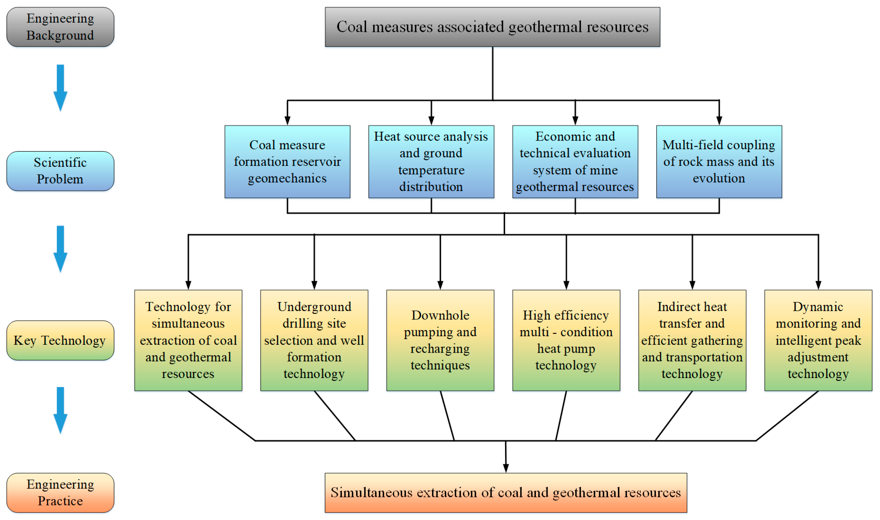
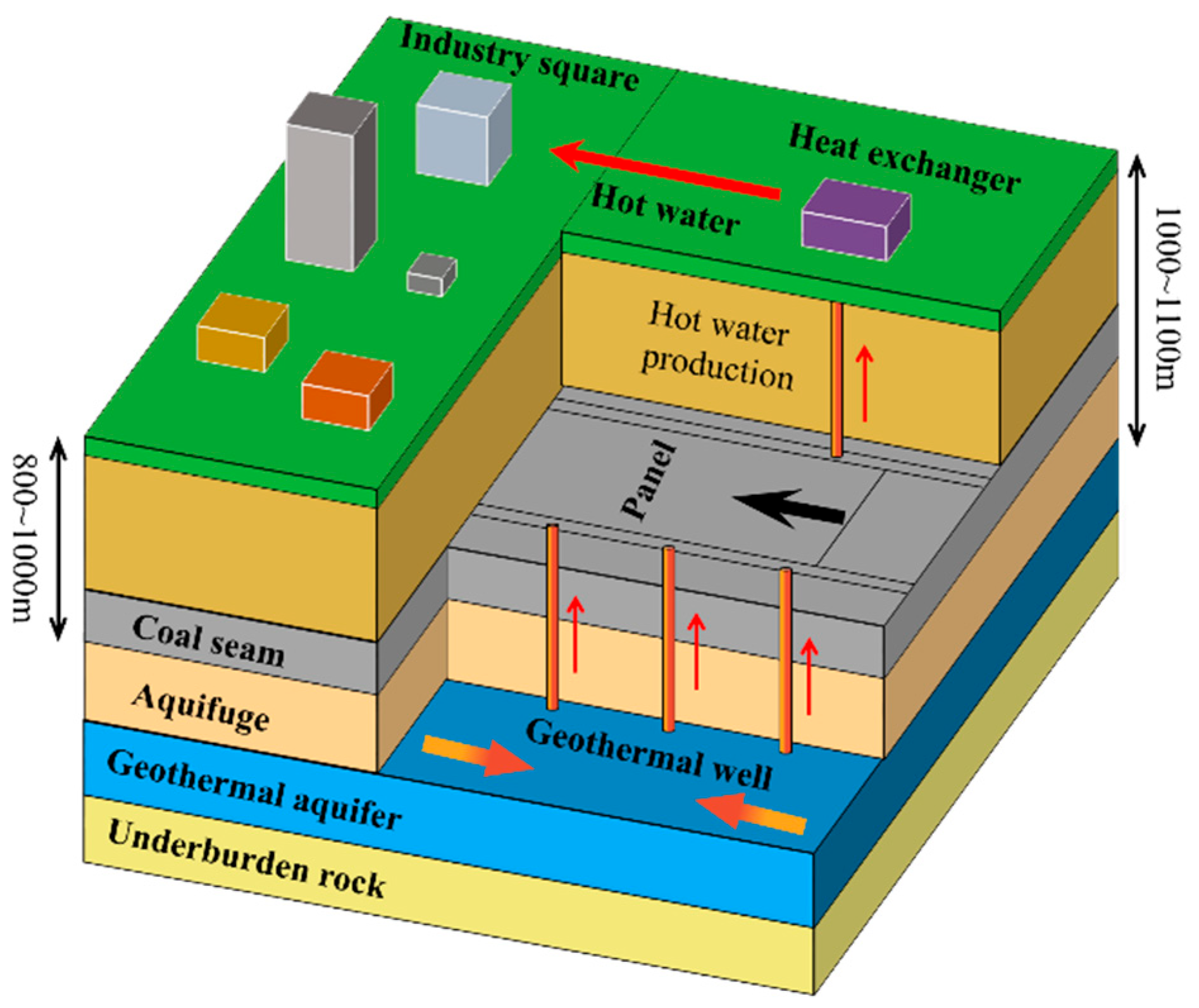
5]. The utilization of mine water, heat, and associated karst aquifers represents a promising opportunity to turn waste into wealth. The Symbiotic Extraction of Coal and Geothermal Resources (SECGR) system offers a viable model for integrated resource management. By utilizing existing mine infrastructure and subsurface data—such as formation permeability, thermal conductivity, and geothermal gradients—the system supports accurate identification of geothermal target zones. Repurposing mine installations including ventilation shafts, drainage networks, and tunnel supports can reduce initial drilling investments by approximately 35–40%. Moreover, the circulation of low-temperature fluids during geothermal operation extracts heat from coal seams, simultaneously mitigating underground thermal pollution through efficient heat exchange. Therefore, addressing the key scientific challenges related to the safe and efficient implementation of SECGR technology is of strategic importance for advancing sustainable energy transition and fostering the synergistic management of coal, water, and geothermal resources [
6] (
Figure 1).
During the implementation of the SECGR technology system, one of the key problems is the stress evolution law and failure characteristics of coal seam floor under coupling of mining disturbance and karst heat storage negative-pressure extraction, namely extraction unloading (hereafter referred to as under MD-EU coupling). To date, scholars have conducted extensive studies on the stress evolution law and failure characteristics of coal seam floor by methods such as theoretical calculation [
7,
8], numerical simulation [
9], similar materials [
10,
11] and in situ testing [
12]. In terms of theoretical calculation, Slesarev [
13] of the former Soviet Union theoretically analyzed the floor strata and established a theoretical formula for predicting water inrush from the floor. Wang et al. [
14] deduced the formula for calculating the maximum failure depth of coal seam floor according to the stress distribution there. Meng et al. [
15], Zhu et al. [
16], and Song and Liang [
17] studied the stress distribution and failure characteristics of coal seam floor based on the abutment pressure distribution in front of the working face and the rock mass limit equilibrium theory. Many scholars put forward theories to analyze the failure characteristics of coal seam floor, including the water inrush coefficient [
18], lower three zones theory [
19], the in situ tensile theory and the zero failure theory [
20]. As for numerical simulation, Tang [
21] is the first to propose the heterogeneous rock fracture process analysis (RFPA) program, which provided a direct understanding of the initiation, propagation and penetration of coal seam floor cracks and the formation of water gushing channels around faults. Lu and Yao [
22] and Wang et al. [
14] made damage and flow modeling based on micromechanics coupling for mining in a confined aquifer, and successfully simulated the gradual development of fractures and the redistribution of stress. Moreover, various multi-field coupling methods including thermal–water–force–machinery coupling [
23], fluid–solid coupling [
24] and thermal–water–force–force–chemistry coupling [
25] models have been proposed. In terms of laboratory experiment, Feng et al. [
26] adopted the self-designed confined water loading system of coal seam floor to simulate the effect of confined water bag on floor waterproof layer, and determined the maximum development depth of floor cracks. Zhang et al. [
27] researched the interaction between floor rock cracks and stress and seepage fields through physical simulation and obtained the evolution law of water inrush from floor cracks under fluid–solid coupling. With respect to in situ testing, Cheng et al. [
28] used the wave velocity of rock mass to test the state of rock mass and determined the development range of water-conducting fractures in floor failure.
Various methodologies have been employed to assess floor failure characteristics. Su and Wei [
29] utilized resistivity tomography technology to monitor floor damage. In investigations into predictive formulas, Gao et al. [
30,
31] accounted for multiple influencing factors and correspondingly applied a nonlinear regression analysis to fit the relationship between these factors and the measured floor failure depth. Furthermore, Wu et al. [
32] developed water inrush prediction models specifically for the Donghuantuo and Zhangcun Coal Mines, providing a theoretical foundation for safety mining.
Although prior research has significantly advanced our understanding of stress evolution and failure characteristics in coal seam floors, most investigations have primarily focused on the influence of isolated factors. Consequently, these studies fail to adequately represent the complex mechanical behavior of the floor under the coupled effects of mining-induced disturbance and the pressure relief from a confined aquifer.
Moreover, in the new technical mode of SECGR, there is still a lack of knowledge and research on the stress evolution law and failure characteristics of coal seam floor under MD-EU coupling. And the corresponding theoretical model remains insufficient. Therefore, it is thus essential to develop a mechanical model under MD-EU coupling in order to accurately determine the stress evolution and failure characteristics of the coal seam floor during the SECGR process. These efforts are crucial for predicting and evaluating the feasibility of the SECGR technology system.
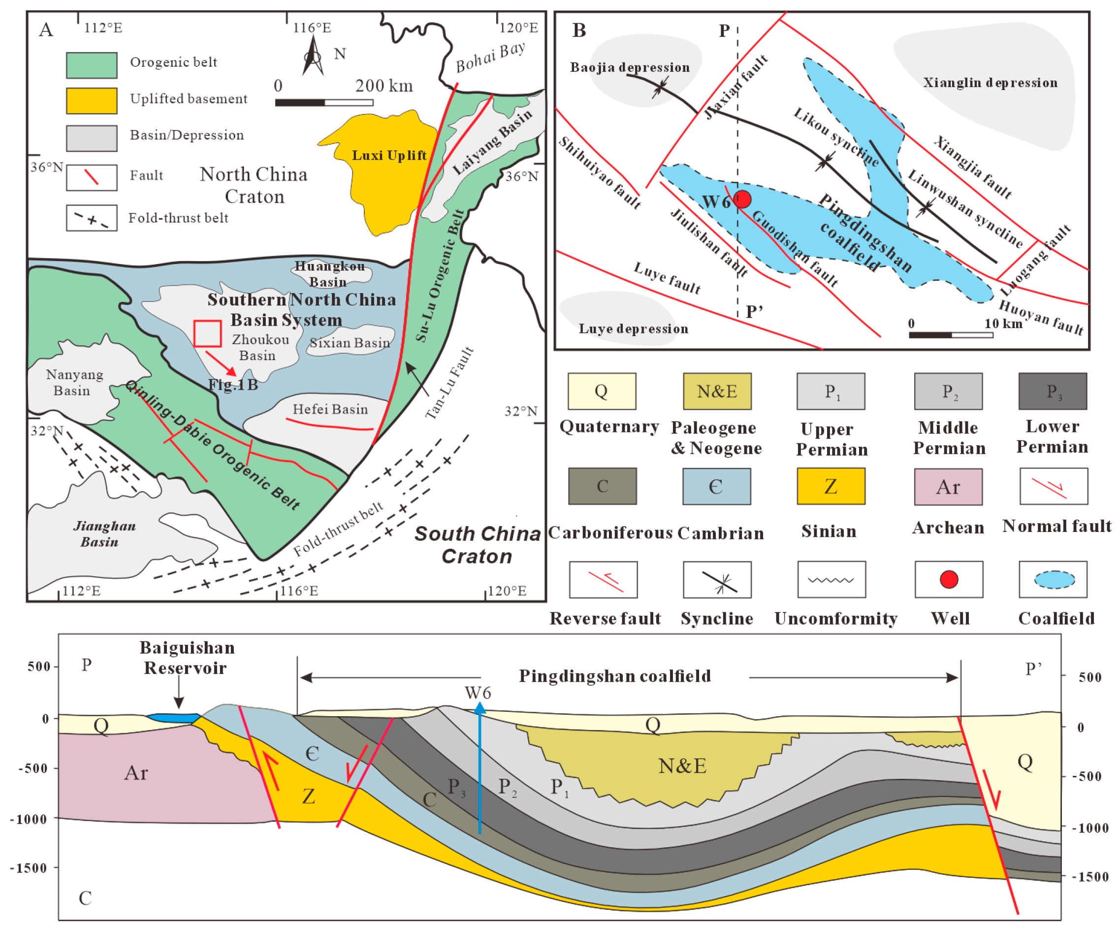
This study focuses on the mechanical behavior of coal seam floor under MD-EU coupling during SECGR. First, the geothermal geological background of Pingdingshan coalfield was analyzed to design the SECGR technology system. Next, considering the coupling effect of mining disturbance and extraction unloading, a hydraulic model was established to analyze the stress evolution law of coal seam floor and quantify the failure characteristics of floor under the coupling effect. Moreover, the FLAC3D fluid–solid coupling numerical model was established, and the failure characteristics of coal seam floor under MD-EU coupling were verified. Finally, the validity of the research was verified by comparing theoretical and numerical simulation results. Furthermore, the influence of the unloading time on the failure characteristics of the floor was investigated.
The research results act as a basis for the field application of the SECGR technology system.
3. Theoretical Analysis
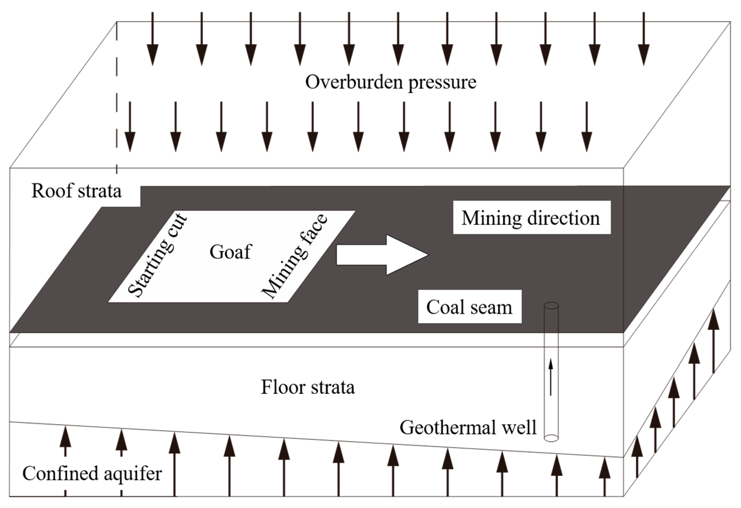
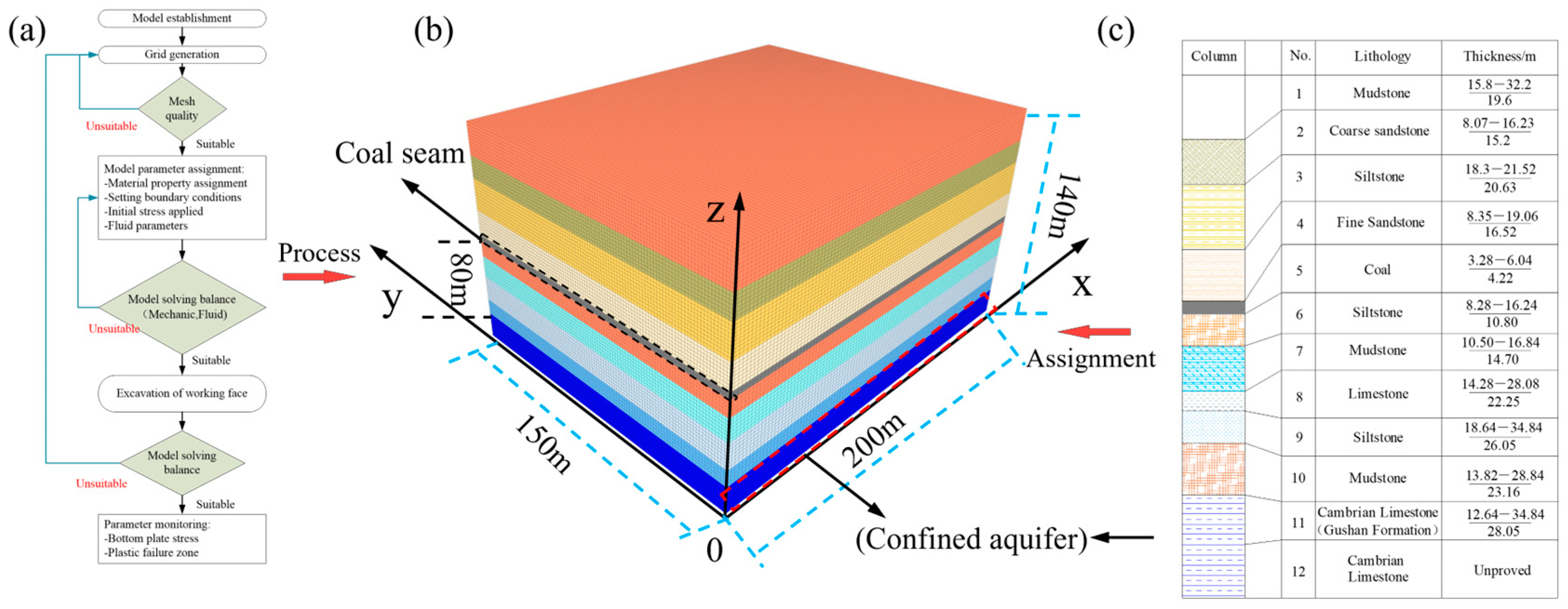
As a case study located in the eastern mining area of the Pingdingshan coalfield, Pingdingshan No. 10 Mine rests upon a Cambrian limestone karst heat reservoir. The main coal seam, with an average thickness of 4 m at a depth of 800–1000 m, is notably underlain by a pressurized (>4 MPa) karst aquifer with temperatures of 50–60 °C, located just 80–100 m below. This unique geothermal setting presents a significant opportunity for the SECGR technology but also introduces critical challenges regarding floor stability. This research therefore aims to explore the theoretical stress evolution and failure characteristics of the coal seam floor under MD-EU coupling, with a multi-field coupling mechanical model established for this purpose (
Figure 4).
To enable effective analysis of the stress evolution and failure behavior of the coal seam floor under the noted conditions, the original multi-field coupled 3D mechanical model of the mine rock mass (
Figure 4) was simplified into a 2D hydraulic model representative of the MD-EU coupling scenario.
Then, the stress evolution law and failure characteristics of coal floor were theoretically analyzed.
3.1. Law of Stress Field Distribution
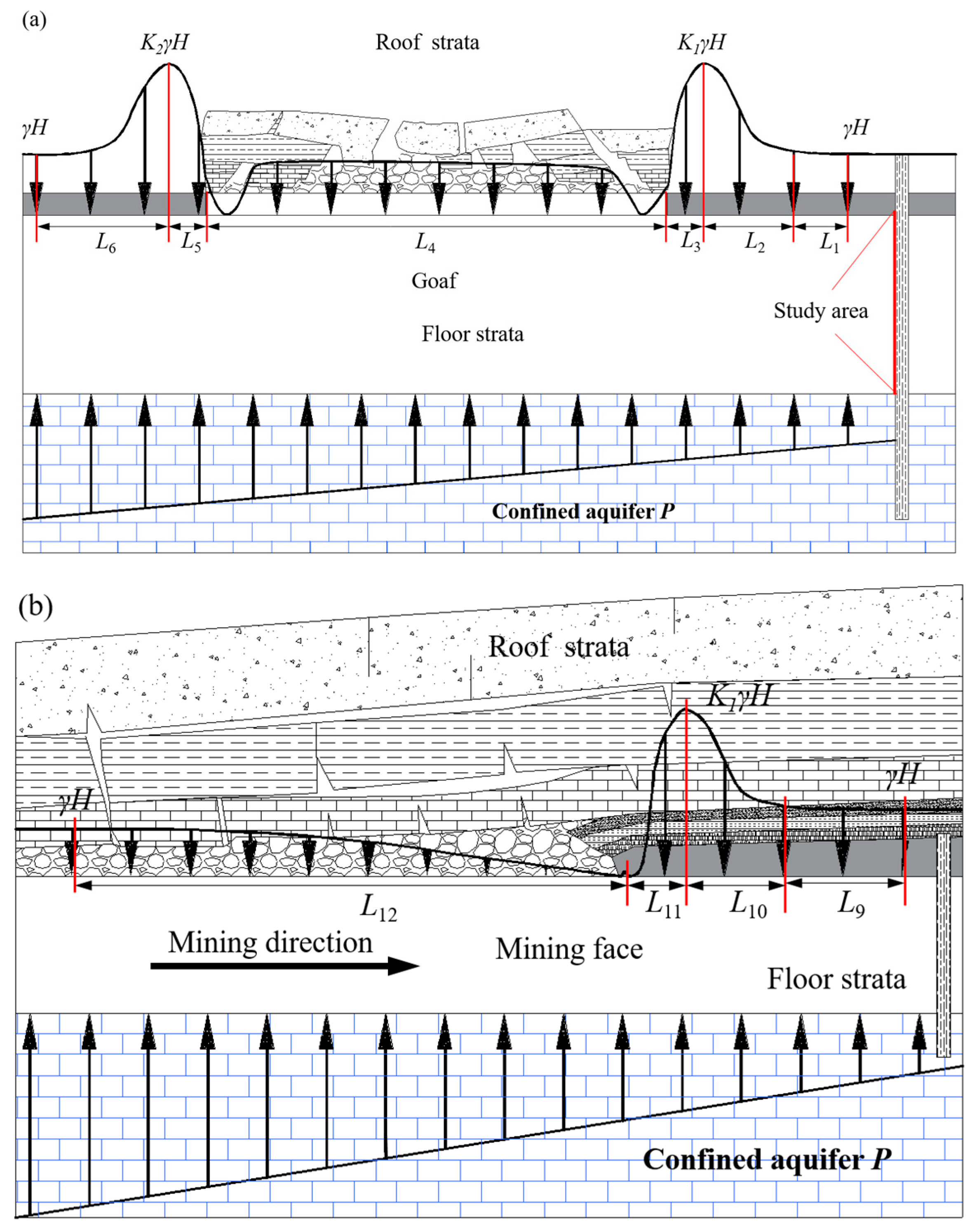
The implementation of the SECGR technology system in Pingdingshan No. 10 Mine necessitates the integrated operation of coal mining above a confined aquifer and negative-pressure extraction from the karst thermal reservoir. This combined activity induces significant stress redistribution and strata failure within the coal seam floor due to mining, while simultaneously altering subsurface pressure conditions through geothermal fluid withdrawal.
Meanwhile, the extraction of geothermal water results in the unloading of the confined aquifer, which further destructs the coal seam floor. The coal seam floor suffers double damage and destruction under MD-EU coupling. Accordingly, a two-dimensional hydromechanical model under MD-EU coupling was established to characterize the stress evolution and identify the failure characteristics of the coal seam floor during the implementation of the SECGR technology.
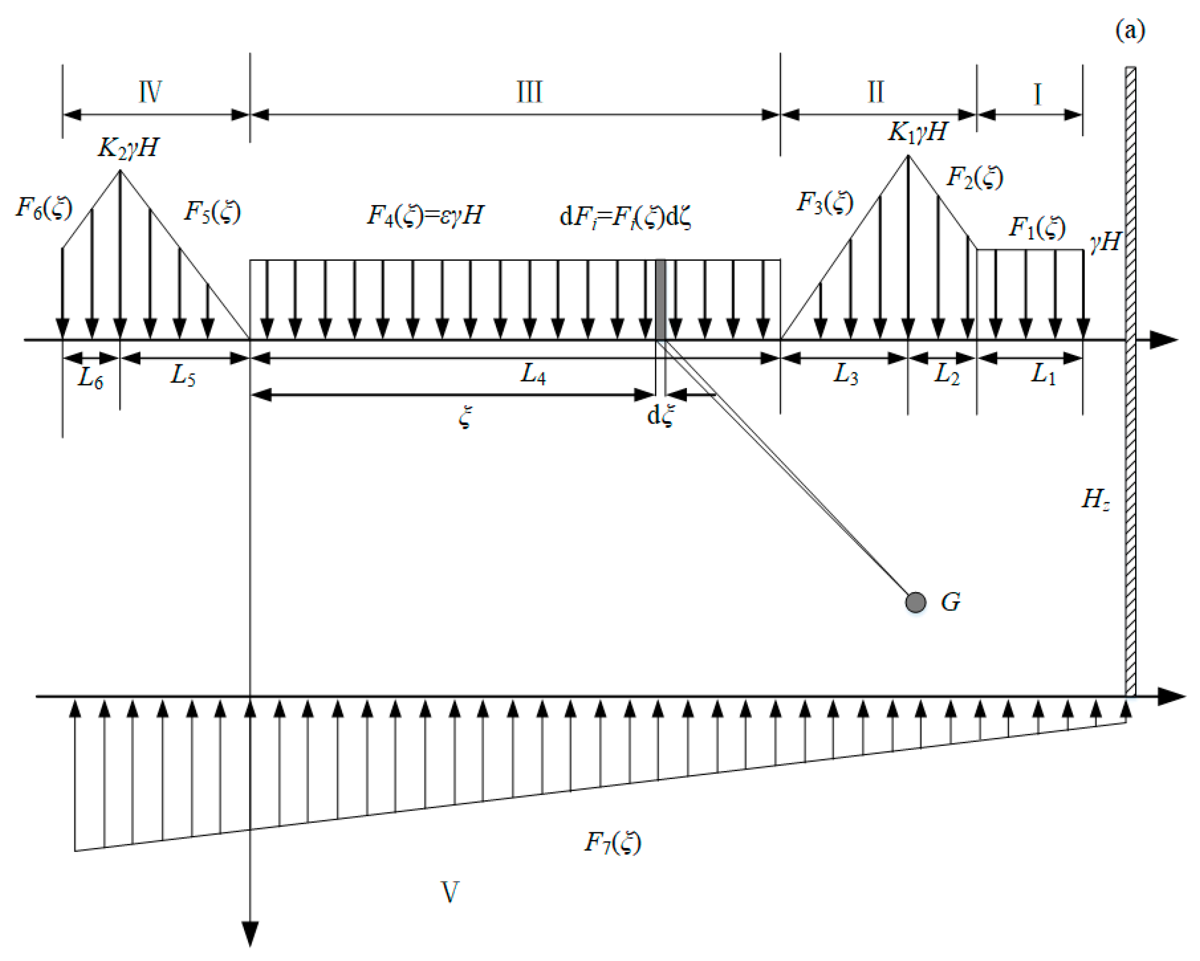
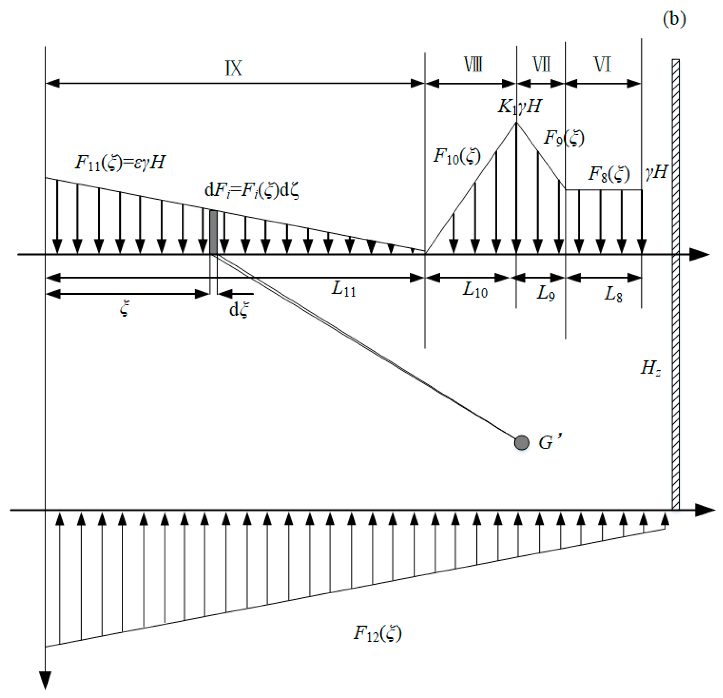
The distribution of upper load and confined water pressure on the floor rock mass along the strike and dip are presented in
Figure 5 and
Figure 6 where I and VI are the undisturbed regions with a stress value of
; II, VI, VII and VIII, which are located in the vicinity of the mining face and the open-off cut, are the stress concentrated regions with stress values of
and
; III and IX are the pressure relief regions formed by roof caving; V is the confined water action region.
Figure 5 depicts the stress distribution within the coal seam floor resulting from the combined influence of mining-induced stress and confined aquifer pressure. For computational analysis, this distribution has been simplified based on the theory of elasticity, employing a linearly distributed equivalent load governing the mechanical behavior.
As displayed in
Figure 6, the high water pressure generated by the floor confined water is another important mechanical source leading to the floor failure, and the unloading effect caused by confined water extraction also further aggravates the floor failure. Meanwhile, in the process of confined water extraction, the assumption that the hydraulic gradient phenomenon occurs in the study area is made.
According to the above 2D HM calculation models (
Figure 6), a mechanical Equation (1) was established to study the stress distribution state at any points G and G’ of coal seam floor under MD-EU coupling.
The detailed expressions of all loads in
Figure 6 are listed as Equation (1) [
37,
38]:
The detailed expressions for all loads depicted in
Figure 6 are provided in Equation (1) [
37,
38].
where
γ is the average bulk density of rock in the floor;
H is the average depth of coal seam mining;
P is the water pressure of the aquifer;
ε is the compaction rate of the goaf;
K1 is the bearing pressure coefficient in front of the strike coal wall;
K2 is the bearing pressure coefficient of the dip coal walls on both sides;
L2, L3, L5 and L6 are the lengths of plastic zones on both sides of the working face, m;
L4 is the length of the working face, m;
L7 is the length of the confined water unloading zone, m;
L9,
L10 and
L11 are the lengths of the plastic zone, the elastic zone and the stress reduction zone along the working face, m. The specific parameters are shown in
Table 1.
A microelement
that is
away from the coordinate origin
O is taken. Then, the concentrated force here can be expressed as
. Furthermore, the
-induced micro-stress component
is:
In Equations (1) and (2), x-ξ and z represent the horizontal and vertical distances from dF or dF′ to G (x, z), respectively.
By transforming Equation (2) from
to
, Equation (3) is defined:
Based on the strike stress (
,
and
) and dip stress (
,
and
), the total stress components (
,
and
) can be calculated as follows:
3.2. Calculation of Failure Depth
The recovery of the working face induces strata movement, primarily resulting in shear deformation within the floor. According to the theory of elasticity, failure occurs when the maximum shear stress at any point exceeds the material’s shear strength. Consequently, based on this premise and the predominance of shear failure, the Mohr-Coulomb criterion is adopted. Equation (6) is thus established to calculate the extent of floor failure, defining the failure criterion as being governed by the shear strength of the rock mass [
17,
39]:
In the previous section, the solution formula of stress component of stope floor under MD-EU coupling in the SECGR technology system has been calculated in the light of the theory of elasticity, and the stress distribution law of floor under unloading action has been explored. To determine the failure depth of the floor, analysis was conducted employing the Mohr-Coulomb criterion, which governs shear failure. Accordingly, the maximum shear stress at any arbitrary point G within the floor can be expressed as:
The constructed function Equation (6) represents the difference between the shear strength and the maximum shear stress, and the rock mass will be destroyed when .
5. Results
Based on the data processing module developed in Python, the vertical, horizontal, and shear stresses at any point within the coal seam floor under MD-EU coupling conditions were systematically calculated using Equations (1)–(5), with corresponding stress nephograms generated to visualize the distribution. Subsequently, the failure depths along both the strike and dip directions of the coal seam were determined by applying the floor failure criterion given in Equation (6). The reliability of the theoretical calculations was further validated by comparing them with numerically simulated failure characteristics and the evolution of the plastic zone during stepwise excavation. Together, these analyses provide a valuable reference for assessing the hydraulic failure behavior of coal seam floors under MD-EU coupling.
5.1. Map of Floor Stress Distribution
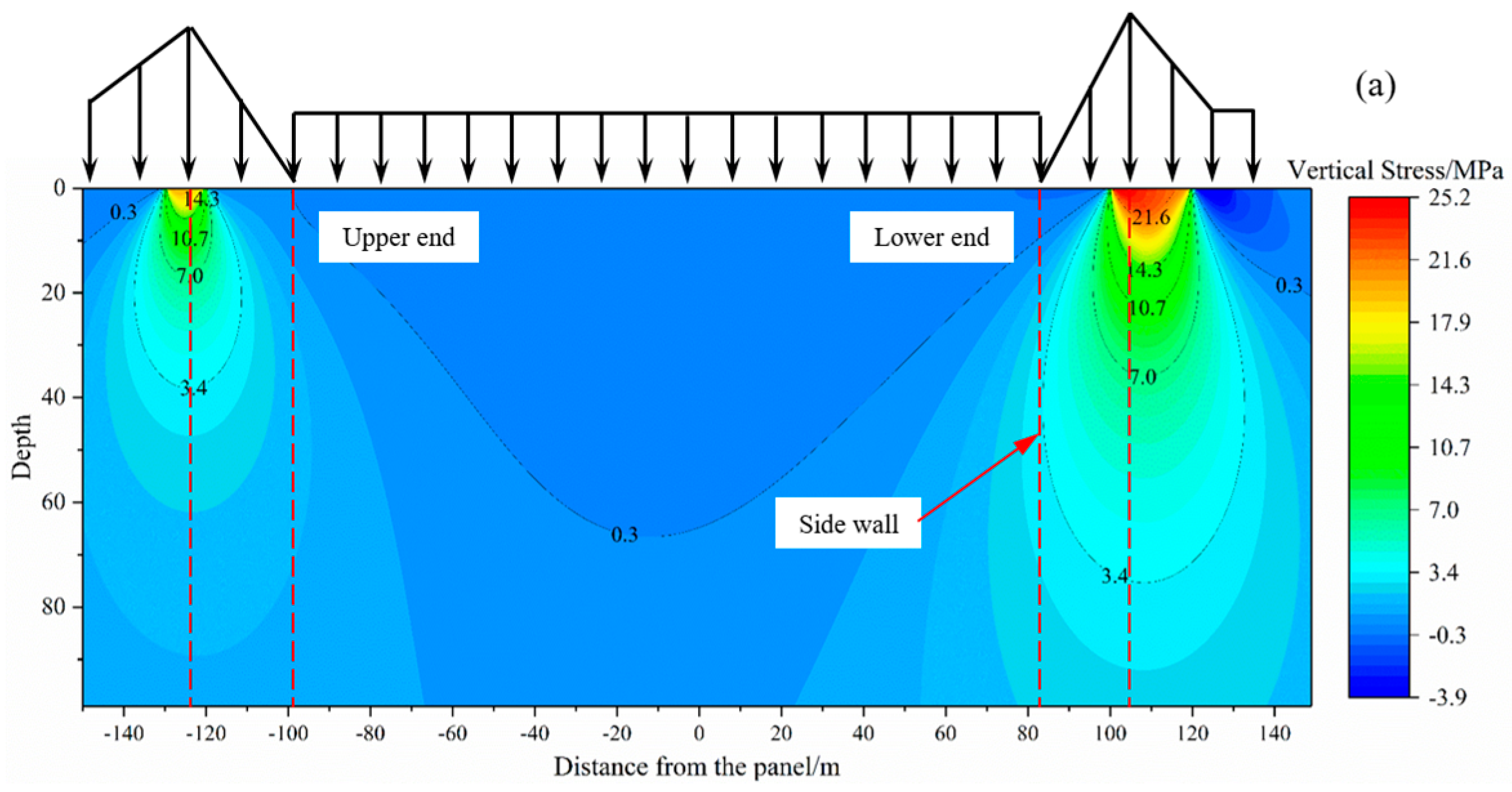
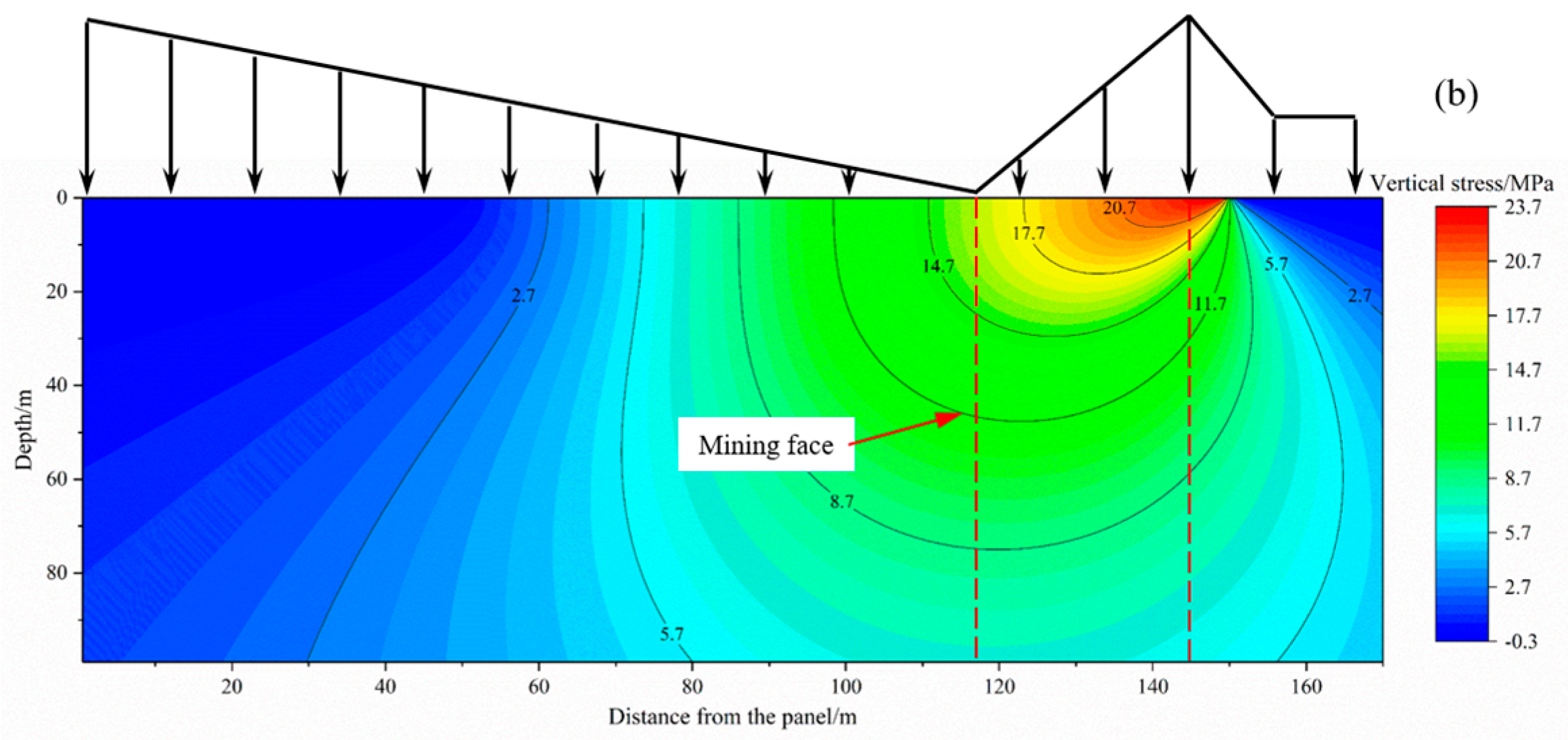
Figure 8 illustrates the vertical stress distribution in the coal seam floor along the strike and dip directions under MD-EU coupling. The distribution is characterized by distinct stress concentration and release areas, a pattern primarily induced by variations in upper abutment pressure. Specifically, the concentration zone, correlating with high abutment pressure, is located beneath the coal pillar, whereas the release area underlies the goaf. The peak vertical stress reaches 23.7 MPa along the strike, while along the dip, the peak values of 14.3 MPa and 25.2 MPa are identified at the elastic-plastic boundary of the coal seam.
Along the dip of the coal seam floor, the vertical stress is obviously asymmetrically distributed, especially in the area with a strong unloading effect. Its value decreases nonlinearly at a decelerating rate with the increase in buried depth. The main reason is that the bearing capacity of karst thermal storage weakens after unloading, which leads to the expansion of the coal seam floor. Furthermore, mining disturbance exacerbates the nonlinear damage accumulation within the floor strata, thereby facilitating a deeper propagation of vertical stress.
Thus, the asymmetric site of floor stress along the dip of the working face is caused by coupling of dynamic disturbance and extraction unloading. In addition, compared with the floor stress distribution map in the literature [
42,
43], the stress distribution of the coal seam floor is still mainly affected by mining disturbance.
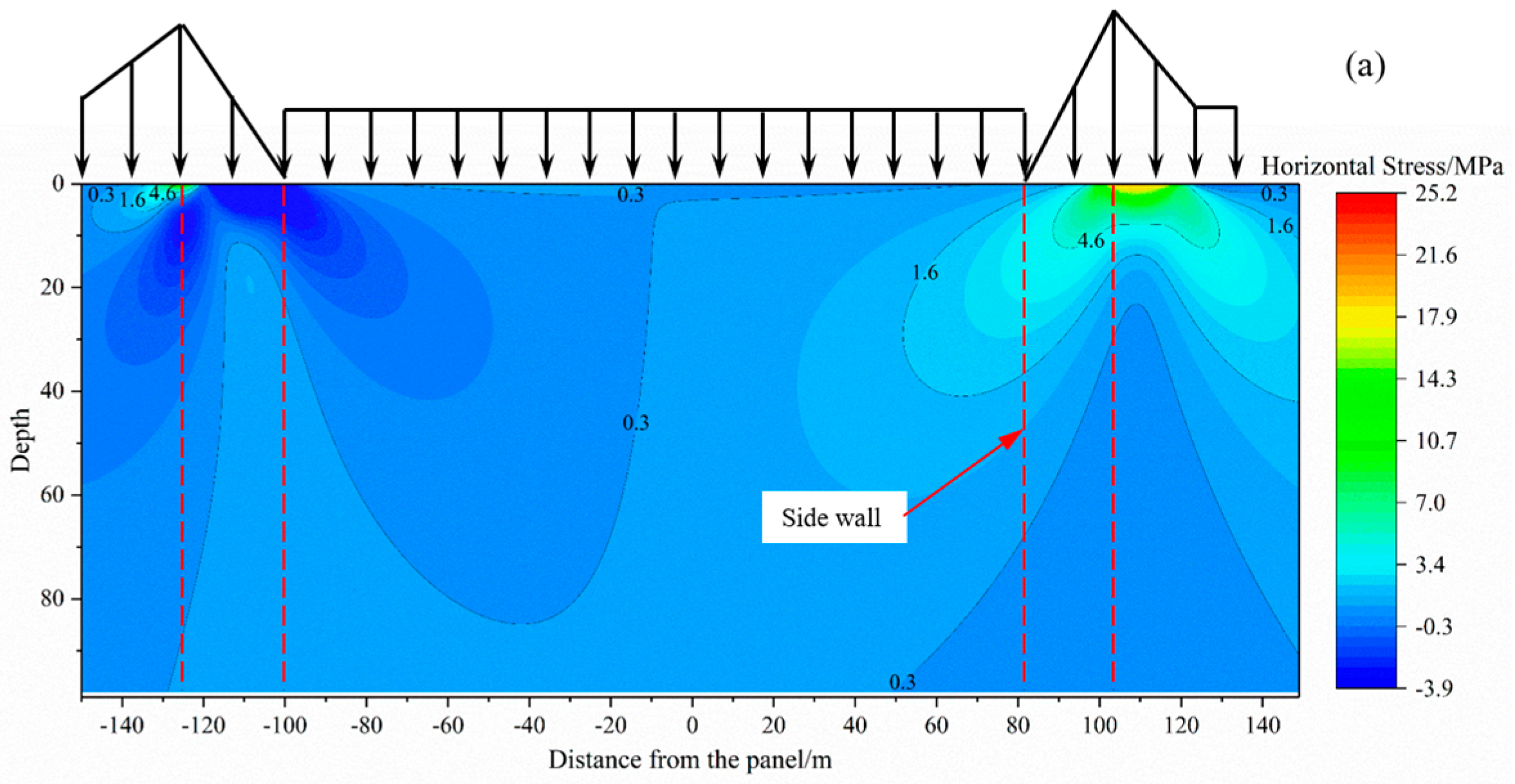
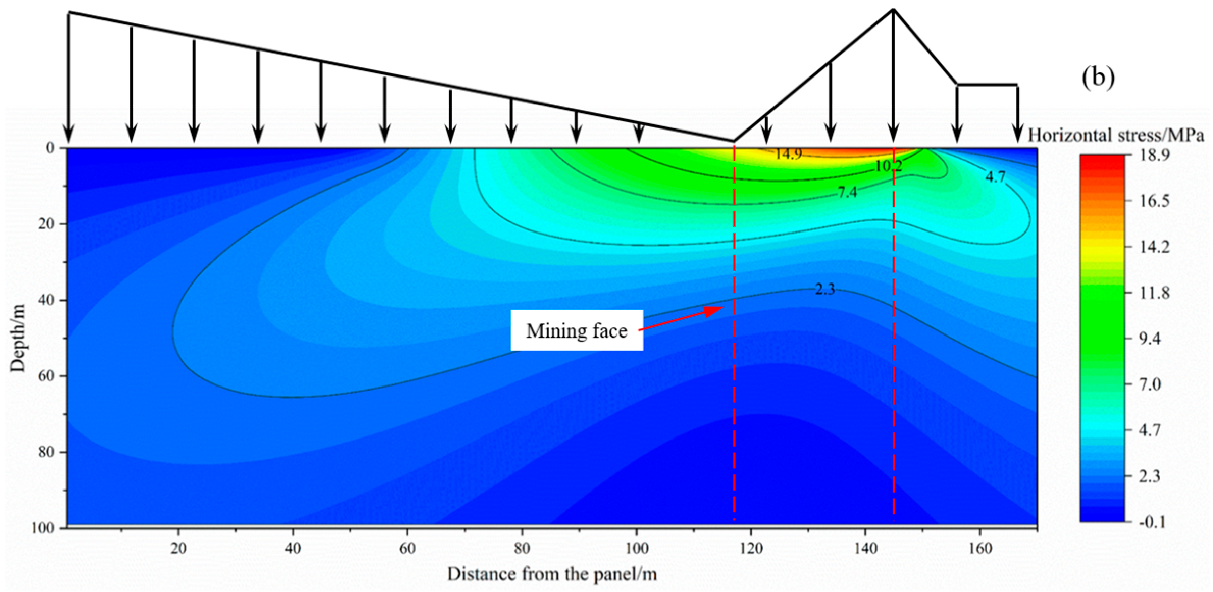
Figure 9 shows the horizontal stress distribution map of the coal seam floor under MD-EU coupling along the working face. As can be observed from
Figure 9, compared with vertical stress redistribution which causes obvious division of the stress concentration area and the release area, horizontal stress redistribution is relatively gentle, and the stress concentration is obviously weakened and mainly occurs within the range of 18 m of the coal seam floor. Below 60 m in the vertical direction, the horizontal stress changes gently or even ceases changing, which indicates that the influence range of horizontal stress shrinks rapidly with the increase in floor depth. Hence, it can be inferred that the continuously distributed normal load induces the generation of both vertical stress and horizontal stress, but the influence range of horizontal stress on the floor is small. This inference is consistent with the computational procedure of Equation (3), which accounts for the relatively minor influence of the vertical distance (z) between any point in the floor and the coal seam on the magnitude of horizontal stress.
Finally, according to the isoline of horizontal stress distribution map, the unloading effect produced by decompression extraction of karst heat storage is an important factor affecting the distribution range of horizontal stress. The more obvious its effect is, the wider the distribution range of horizontal stress and the more obvious its diffusion are. And the degree of stress diffusion and attenuation also rises with the increase in unloading effect.
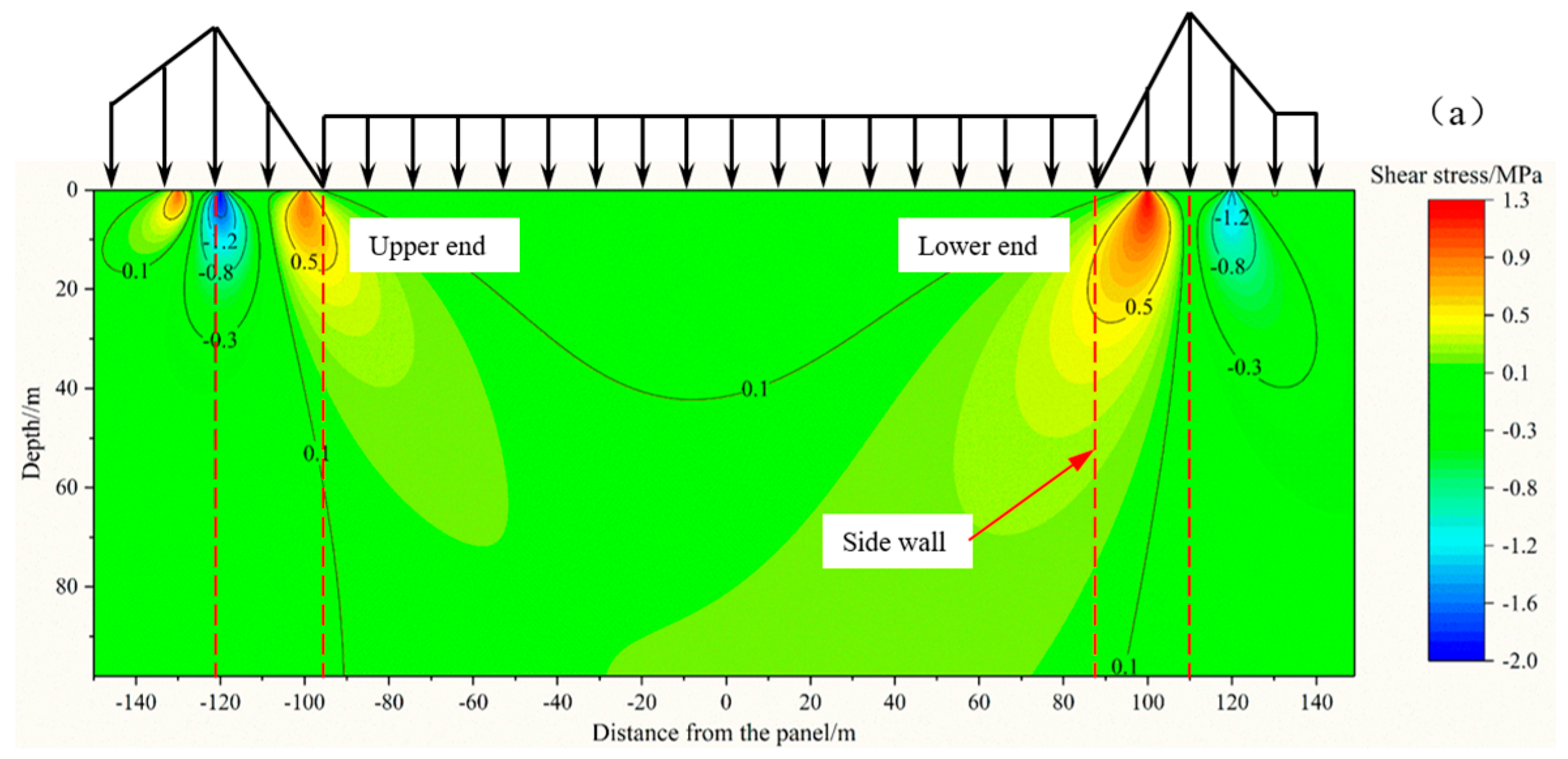
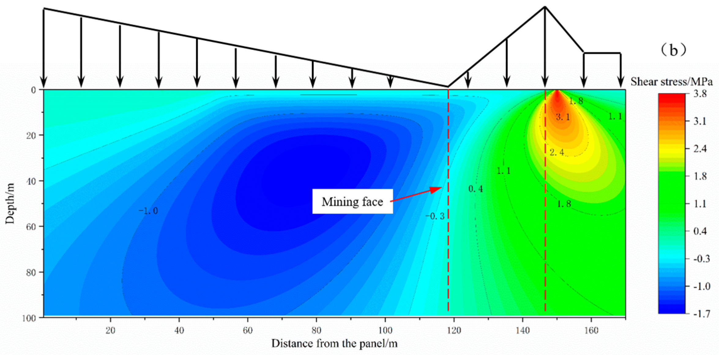
Figure 10 shows the shear stress distribution map of the coal seam floor along the dip and strike of the working face under MD-EU coupling. Clearly, the maximum shear stress occurs at the load edge. In
Figure 10a, the shear stress presents a saddle-shaped distribution between the peak values of the load stress, which is basically symmetrical along the vertical line of the working face, and the shear stresses at both ends obliquely propagate downward at a certain angle with the normal direction of the floor. A positive and negative shear couple occurs in the underlying rock layer corresponding to the load edge area, which makes the floor rock mass more prone to compression-shear or tension-shear deformation and failure. From
Figure 10a, stress concentration occurs in the underlying rock mass at both ends of the working face, and the maximum shear stresses are basically equal, about 1.3 MPa. Despite the small value of peak stress in the shear stress concentration area, its influence range is broader, indicating that the vertical stress of the floor under unloading aggravates floor deformation and expansion, which leads to an obvious increase in the range of shear stress. However, the expansion and deformation of rock mass reduce the stress concentration value of shear stress. Shear yield easily occurs in shear stress concertation areas in the coal seam floor, resulting in the development of shear cracks and the formation of water channels. Therefore, it is necessary to pay attention to the water level change in the shear stress concertation areas in the floor during coal mine production.
5.2. Map of Floor Failure Depth
Using Python 3.11 and Origin 2024 software, the theoretical failure modes of the stope floor along the dip and strike of the working face were obtained by substituting relevant parameters (
Figure 4). The contour maps in the figure were obtained by the above formulas, and the parts where the depth is smaller than 0 represent the failure of floor rock mass.
Figure 4 presents the contour plot of floor failure derived from Equation (7). Based on the calculation results of this equation, failure is considered to occur where the maximum shear stress τmax falls below zero. Using the criterion τmax = 0, we have delineated the preliminary failure boundary of the floor, as indicated by the dashed line in
Figure 4.
Figure 11 shows failure depth distribution of the coal seam floor along the strike and dip of the working face under MD-EU coupling. According to
Figure 11, under MD-EU coupling, the failure mode of the floor resembles that of the shear stress distribution area, and the failure mode along the strike can be divided into two parts. Specifically, the failure mode beyond 80 m behind the working face tends to be stable and straight, while that from 80 m behind the working face to 50 m in front of the working face presents an inverted-S shape. The failure mode along the dip presents an approximately inverted-saddle shape, which agrees with the failure mode of the floor obtained by Song [
39,
42]. Along the strike, the maximum failure depth of the floor in front of the coal wall is about 45 m, and the failure tends to further develop downwards; additionally, the failure depth of the floor behind the working face is about 20 m. Along the dip of the working face, the maximum failure depth is 28 m, and a failure mode that is deep at both ends and shallow in the middle is formed. The reason is that the areas near the coal pillars at both ends undergo heavy stress concentration and witness the appearance of shear force couples; consequently, the failures easily occur from both ends gradually expand and extend to the floor of the central goaf and connect with each other. In addition, the shear failure depth of the floor is large within the range of peak abutment pressure, but it is relatively small in the pressure relief section of the goaf. In summary, extraction unloading caused by negative-pressure extraction of karst heat storage leads to the uneven failure depth of the floor, and the failure depth is larger in the areas with strong extraction unloading, which is consistent with the unloading effect on shear stress.
A comparison with existing literature reveals that the computational results from the hydro-mechanical coupling model established in this study are generally consistent with the floor stress model developed by Song et al. in terms of both stress distribution patterns and magnitude. This consistency in observed behavior supports the rationality of the assumptions and parameters adopted in our work, thereby providing a foundational basis for our numerical simulations.
5.3. Map of the Floor Plastic Zone Along the Strike
Generally speaking, the coal seam floor experiences stress redistribution under MD-EU coupling, which induces different degrees of unloading damage to it. However, the unloading effect caused by decompression extraction of karst heat storage is mainly reflected in the non-uniform regional damage caused by unloading of confined water and its overlying strata.
Figure 12 shows the relationship between the floor failure depth, the development area of the plastic zone above confined water and the advancement distance of the working face during numerical simulation.
Figure 12 shows the floor plastic zone along the strike at different mining distances under MD-EU coupling. As exhibited
Figure 13, in the early stage of mining, the floor is barely affected by MD-EU coupling, and the failure zone is almost symmetrically distributed in the shape of an inverted saddle. The predominance of shear failure suggests that the effective aquiclude between the confined aquifer and the coal seam remains sufficiently thick at this stage, while the extraction-induced unloading from karst thermal reservoir depressurization has only a marginal influence on the floor failure depth.
With the continuous advancement of the working face, the floor failure depth gradually increases, and the failure continuously moves forward, while the plastic zone expands downwards in an asymmetric manner. It can be seen from the failure state that under MD-EU coupling, the floor below the working face mainly undergoes shear failure, while the rock mass lying under the goaf primarily experiences tensile failure. This corresponds to the position of the shear couple in
Figure 10a. Moreover, the final failure mode of the coal seam floor resembles the theoretical calculation results, the inverted-S-shaped failure mode near the working face. Therefore, the unloading effect caused by decompression extraction of karst heat storage further aggravates the floor failure, and the distribution of plastic zone coincides with the theoretical calculation results; additionally, the plasticity develops vigorously in areas with a strong unloading effect.
5.4. Map of the Floor Plastic Zone Along the Dip
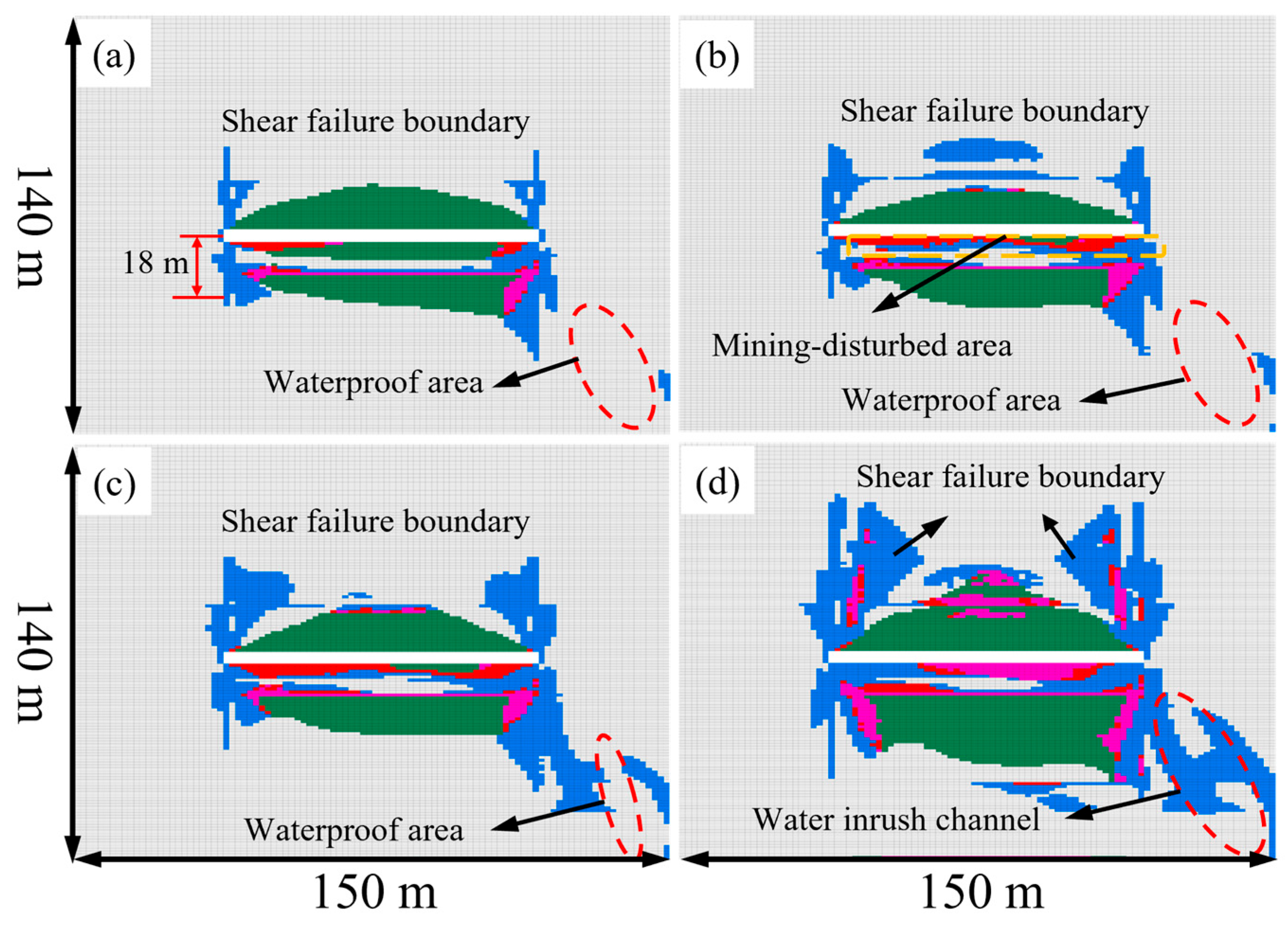
Figure 13 depicts the evolution of the plastic zone along the floor’s dip direction under extraction-induced unloading. As illustrated, the failure process evolves through four distinct stages: the undisturbed stage, crack initiation stage, crack development stage, and finally, crack coalescence stage. Analysis indicates that as the working face advances, floor failure progressively extends from both ends toward the center. The ultimate failure mode, characterized predominantly by shear failure with a depth range of 18–46 m, demonstrates strong agreement with both theoretical calculations and previous research findings by Liang et al. [
39,
43].
Meanwhile, three distinct characteristic zones are identified within the floor rock mass: the mining-induced failure zone, the intact aquiclude (complete rock stratum), and the unloading-activated zone.
Once the discrete cracks under high confined water pressure are hydraulically connected with the mining failure area, a large amount of groundwater will enter the roadway uncontrollably, thus causing water inrush accidents. In
Figure 13, the maximum failure depth and the shear-couple-induced tensile-shear damage zone appear in the unloading zone of decompression extraction of karst heat storage. Based on the above results, the numerical simulation results basically agree with the theoretical calculation results, and the calculation results can provide theoretical explanation for the field application of the SECGR technology system.
6. Discussion
Based on the integrated theoretical and numerical simulation results presented above, the MD-EU coupling mechanism significantly governs the stress evolution and failure characteristics of the coal seam floor.
The essence of their effect on the floor rock mass is to induce unloading failure of the rock mass. As disclosed in the research of Zhao et al. [
44,
45], the two key factors of unloading failure are unloading stress and unloading time. Among them, unloading stress is mainly reflected in the mining disturbance intensity of the working face and the unloading effect of high-pressure confined water, while unloading time is mainly manifested in the speed of working face advancement and the speed of karst heat storage depressurization extraction. Specifically, faster working face advancement and karst heat storage depressurization extraction correspond to a higher unloading speed and a shorter unloading time of rock mass. To ensure safe and economic implementation of the SECGR technology system, this study focuses on the influences of working face advancement and karst heat storage depressurization extraction speeds (unloading time) on the failure characteristics of stope floor rock mass. Furthermore, it also aims to explore more factors influencing the failure characteristics. Such a study is valuable in engineering applications. In view of the above fact, the deformation and failure of stope floor rock mass under the influences of working face advancement and karst heat storage depressurization extraction speeds (unloading time) are analyzed and discussed in this section.
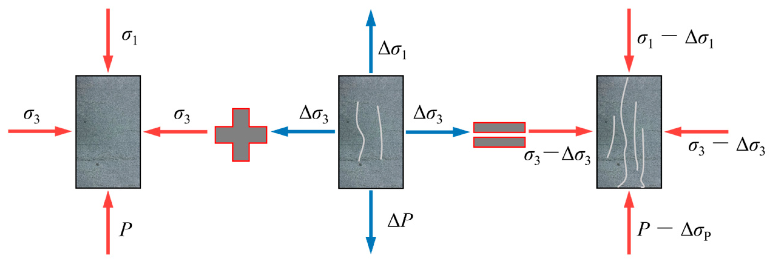
Unloading induces rebound deformation in the rock mass along the unloading direction. As described by the constitutive relation of rock mass, this deformation generates tensile stress in the same direction. Thus, the MD-EU coupling effectively superimposes a reverse tensile stress onto the pre-existing stress field. By defining the unloading stresses along the maximum and minimum principal stresses as Δσ
1 and Δσ
3, respectively, the resultant stresses under MD-EU coupling become (σ − Δσ
1) and (σ − Δσ
3). The corresponding stress decomposition is illustrated in
Figure 14.
In the unloading process, the relationship between the damage factor D of rock mass, unloading stress Δ
σ and unloading time
T (
T1 +
T2) is assumed as follows:
where
and
are rock mass parameters, respectively;
T1 indirectly represents the speed of working face advancement; and
T2 indirectly represents the speed of confined water extraction. The faster the working face advancement and confined water extraction, the smaller the unloading times
T1 and
T2,
T =
T1 +
T2.
According to Lemaitre’s principle of strain equivalence [
46], the constitutive relation of damaged material (
D ≠ 0) can be deduced from the constitutive relation of nondestructive material (
D = 0). In the process of derivation, the effective stress tensor of damaged material
can be substituted for that of lossless material
. The relation between effective stress tensor
and
can be expressed as follows:
where
I is the unit tensor.
The creep equation in the 1D Burgers model [
47] is developed into a 3D one by analogy. where
is the total axial strain;
is the bulk modulus, GPa;
and
are shear moduli;
and
are the viscosity coefficients,
. For the convenience of analysis, it is assumed that the confining pressure of rock mass is equal, that is
, and
is replaced with
. In this way, the creep equation is simplified as:
By substituting Equations (10) and (11) into Equation (12), the creep constitutive equation considering unloading stress and unloading time is obtained as follows (
Table 3):
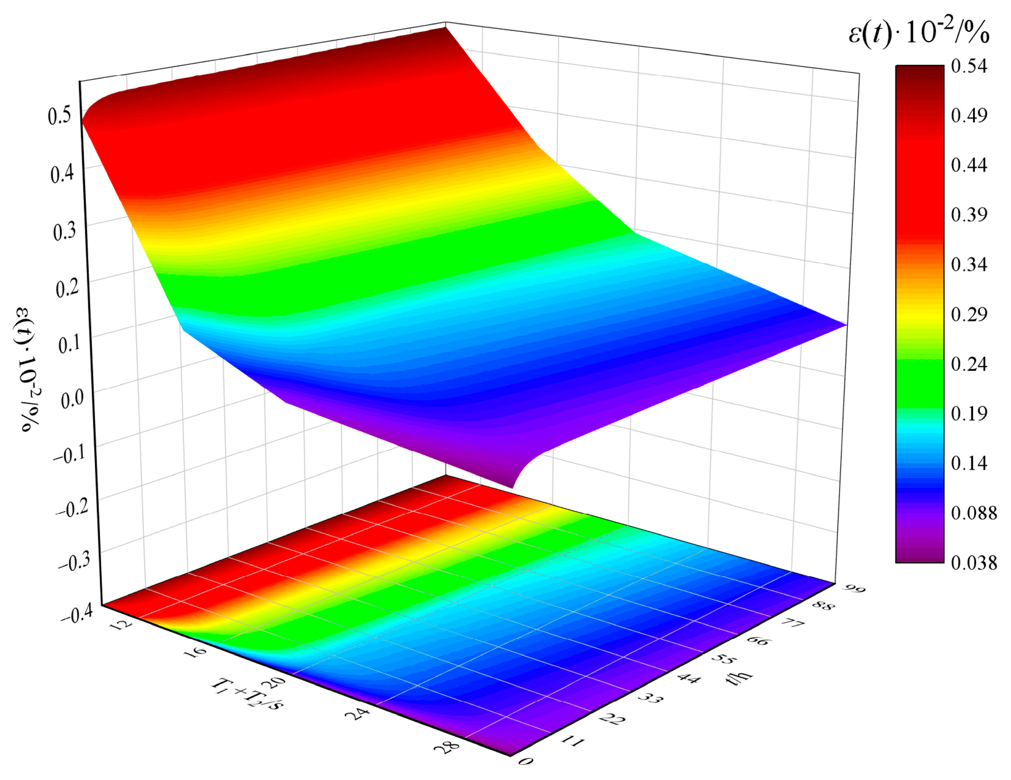
Based on the mechanical parameters of floor rock mass and the different unloading times (
T1 +
T2) in the paper, the creep law of rock mass was obtained (
Figure 15). As illustrated in
Figure 15, the unloading rate (working face advancement and karst heat storage depressurization extraction speeds) has a considerable influence on the failure degree of rock mass. The faster the working face advancement and karst heat storage depressurization extraction (the smaller
T1 +
T2), the more severe the deformation of rock mass and the higher its damage degree. In the initial stage of mining, the failure degree of rock mass increases linearly. After MD-EU coupling for a certain time, the failure degree tends to flatten, no longer increasing or just increasing slowly. This theoretically shows that proper control of working face advancement and karst heat storage depressurization extraction speeds can effectively slow down the failure speed of floor rock mass. Moreover, the failure degree of the floor has a certain limit, and it will not continue to increase when it exceeds the limit value. However, the actual influence characteristics of working face advancement speed (unloading speed) on the failure mode of floor rock mass need further field verification.
7. Conclusions
This study designed and implemented the SECGE system technology based on the engineering background of Pingdingshan No. 10 Mine. This system offers a novel approach to integrated resource extraction and environmental conservation. A 2D hydraulic calculation model of the floor under MD-EU coupling model was used to investigate stress field distribution patterns and failure mechanisms in the coal seam floor during coal and thermal resource extraction. Numerical simulations further analyzed the dynamic evolution of floor damage characteristics under extraction-induced stresses. Additionally, the Burgers viscoelastic model was applied to quantify time-dependent rock mass damage evolution caused by mining-induced unloading effects. The main conclusions of this study are as follows:
(1) Following multiple tectonic events, certain strata in the Pingdingshan coalfield have been eroded, resulting in an overall uplift structure with a central syncline. This geological framework has given rise to a high geothermal heat flow ranging from 60 to 80 mW/m2, forming geothermal resources associated with coal measures. These conditions provide a natural foundation for the application of the SECGR technology system.
(2) Under the coupled effects of mining disturbance and extraction unloading (MD-EU), vertical stress exhibits an asymmetric distribution, with mining disturbance being the dominant factor governing stress redistribution. Both the distribution range of horizontal stress and the extent of stress attenuation increase with greater unloading. Shear stress displays a saddle-shaped distribution on the goaf floor, where shear couples induce shear failure. Unloading expands the distribution range of shear stress while reducing its peak magnitude.
(3) The mining-induced failure zones along the strike and dip of the coal seam floor exhibit inverted-S and inverted-saddle shapes, with respective failure depths of 35 m and 28 m, consistent with numerical simulation results. Simulations further indicate that hydraulic unloading induces asymmetric failure in the floor. As mining proceeds, floor failure undergoes four distinct stages: undisturbed, crack initiation, crack development, and crack connection. Additionally, three characteristic zones are identified in the floor rock mass: the mining failure zone, the waterproof zone, and the unloading activation zone.
(4) The Burgers model provides a valid framework for characterizing the relationship between unloading rates and rock mass damage evolution. Based on the creep equation derived from this model, the influence of unloading rate on floor failure mechanisms was analyzed. During initial mining stages, higher unloading rates lead to more severe rock mass damage, showing an approximately linear increase. With continued mining, the extent of rock mass damage eventually stabilizes or increases only marginally.
