
Advances in Deflocculant Utilisation in Sustainable Refractory Concrete with Refractory Waste


Abstract
1. Introduction
2. Materials and Methods
2.1. Characteristics of Raw Materials
2.2. Methods of Testing and Sample Preparation
3. Experimental Part
3.1. Fresh Paste Properties
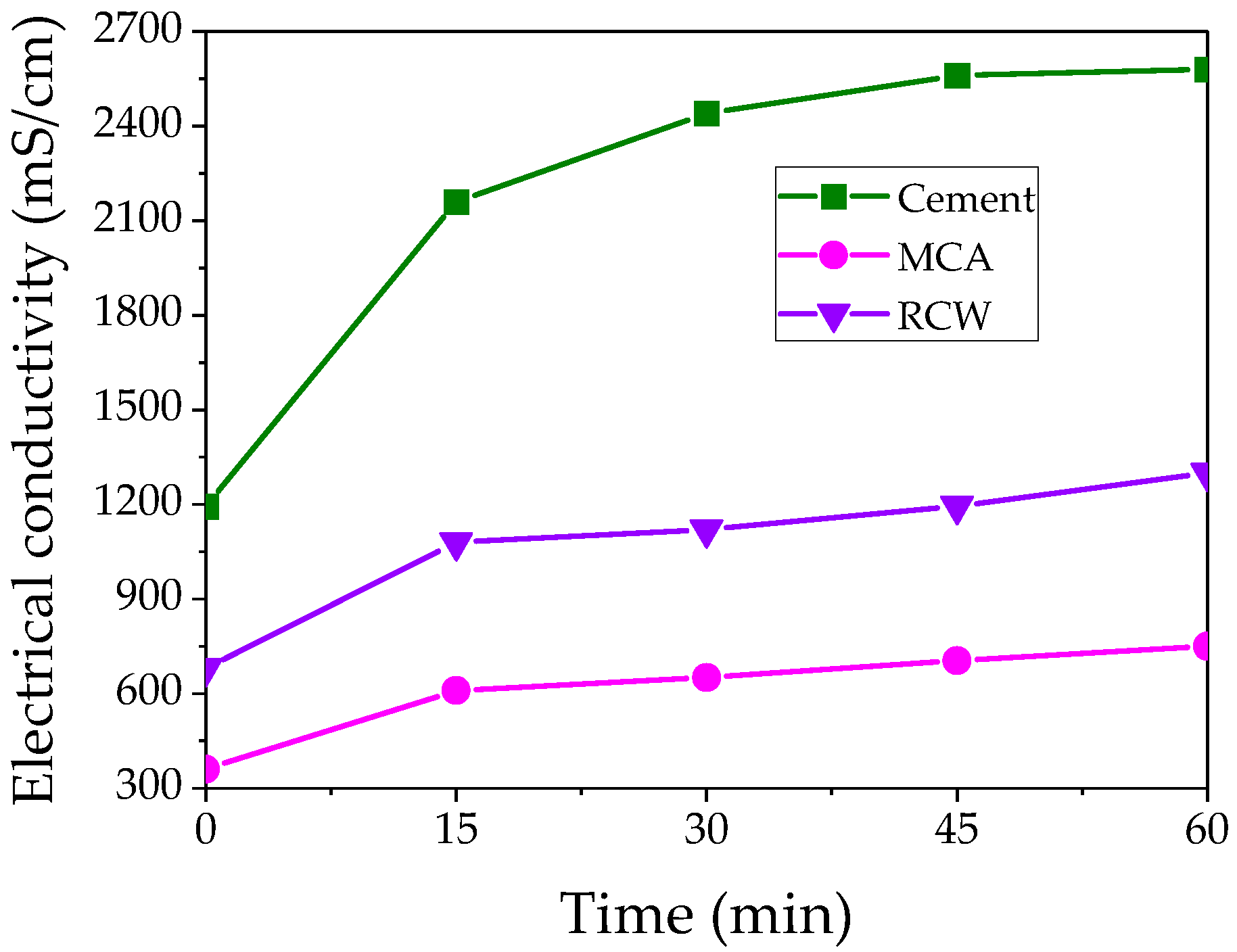
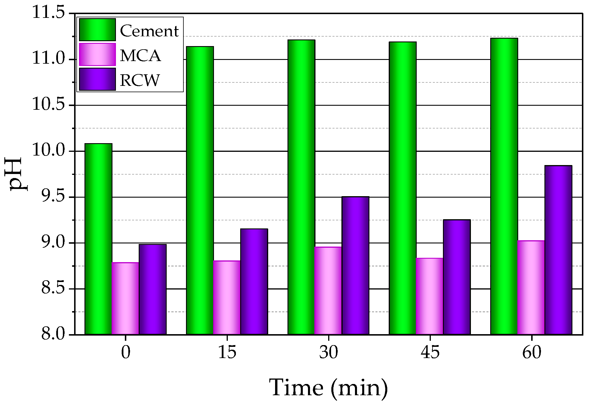
3.1.1. Electrical Conductivity and pH
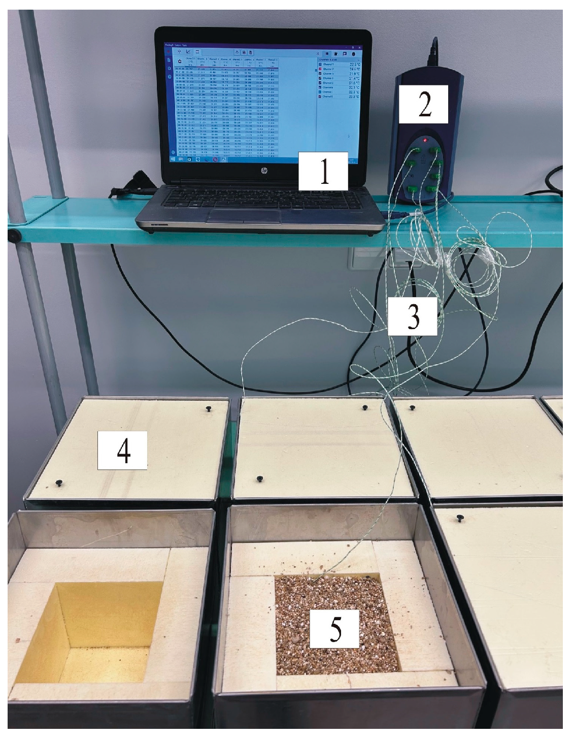
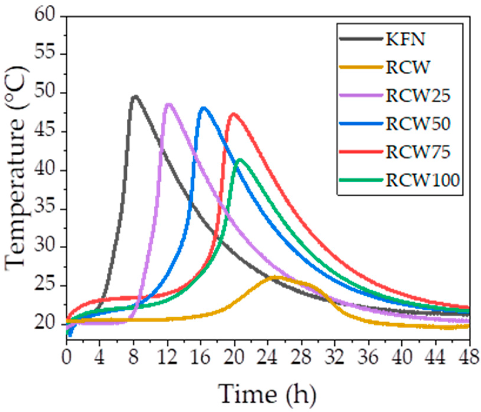
3.1.2. Exothermic Reaction
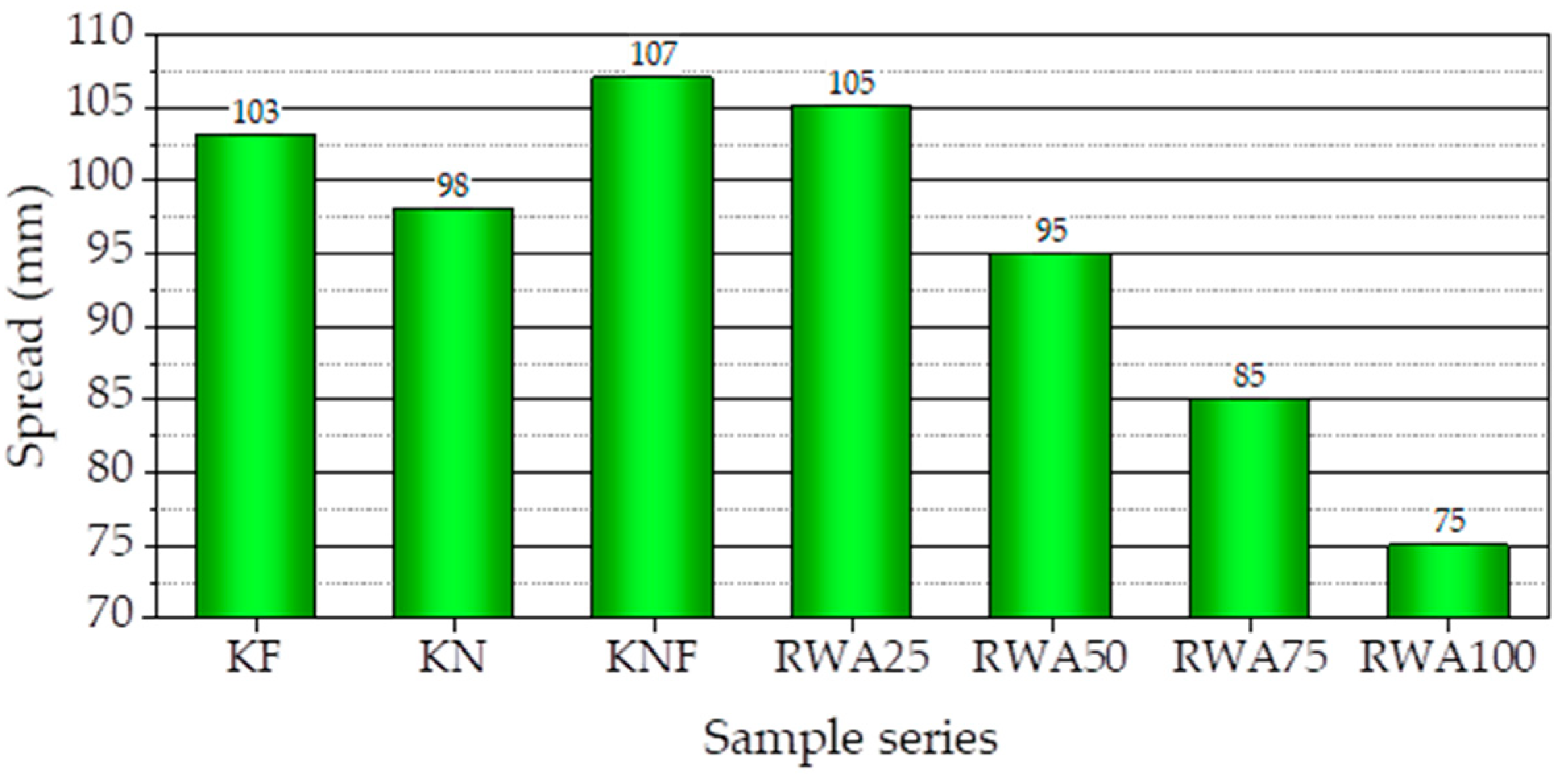
3.1.3. Spread
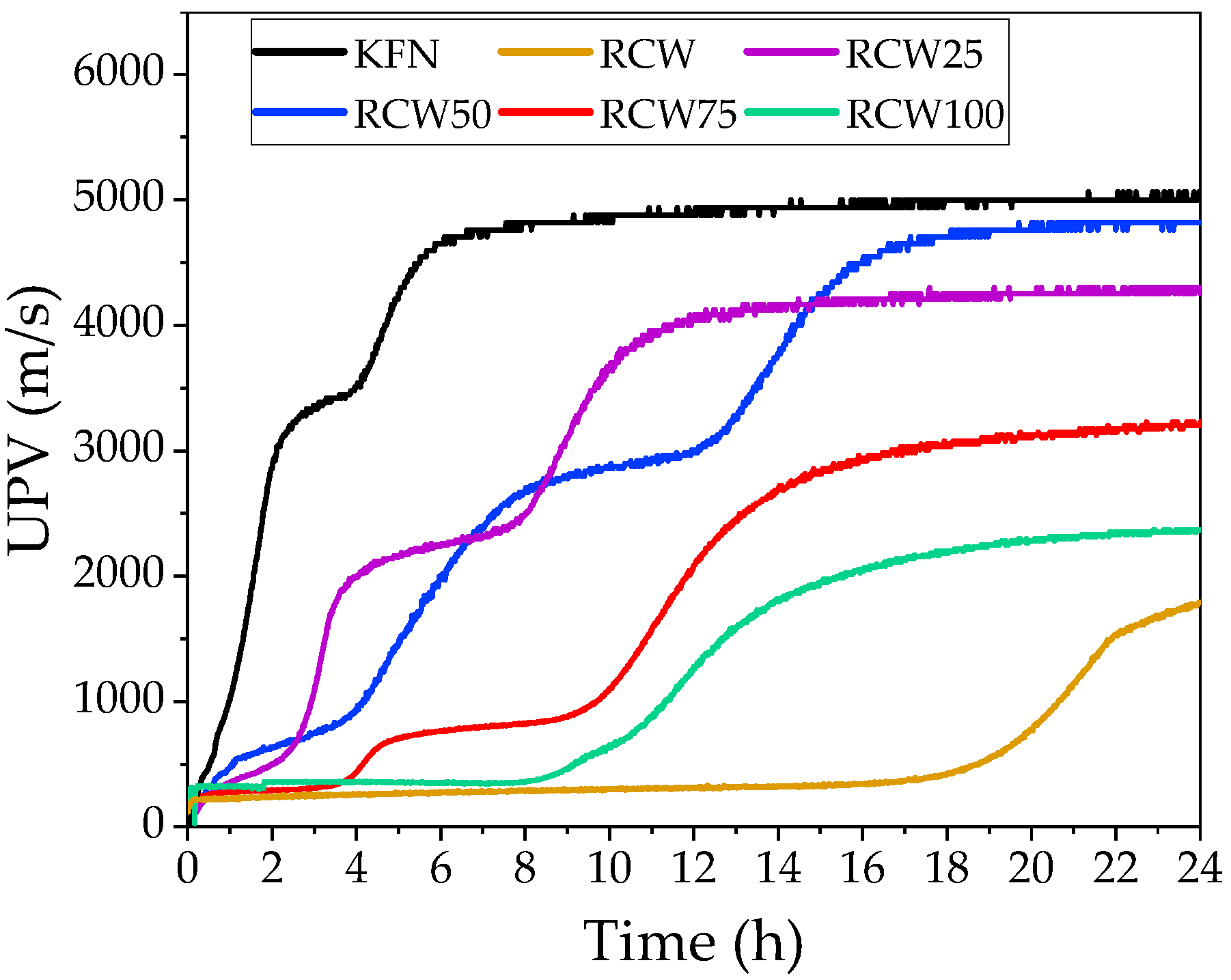
3.1.4. Ultrasonic Pulse Velocity
3.2. Concrete Properties
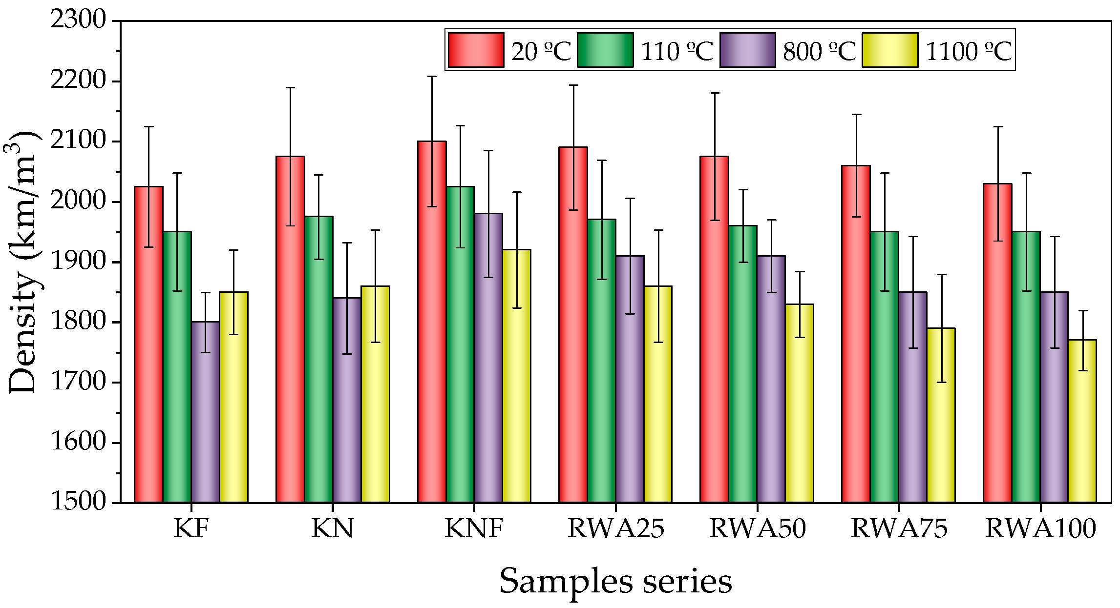
3.2.1. Density
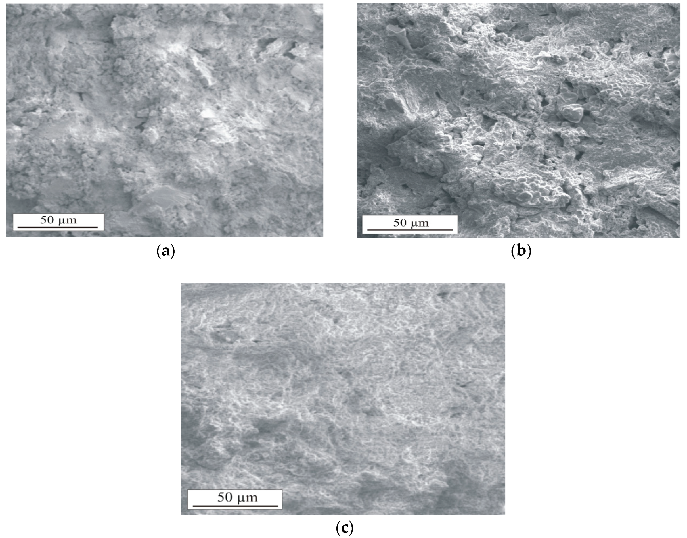
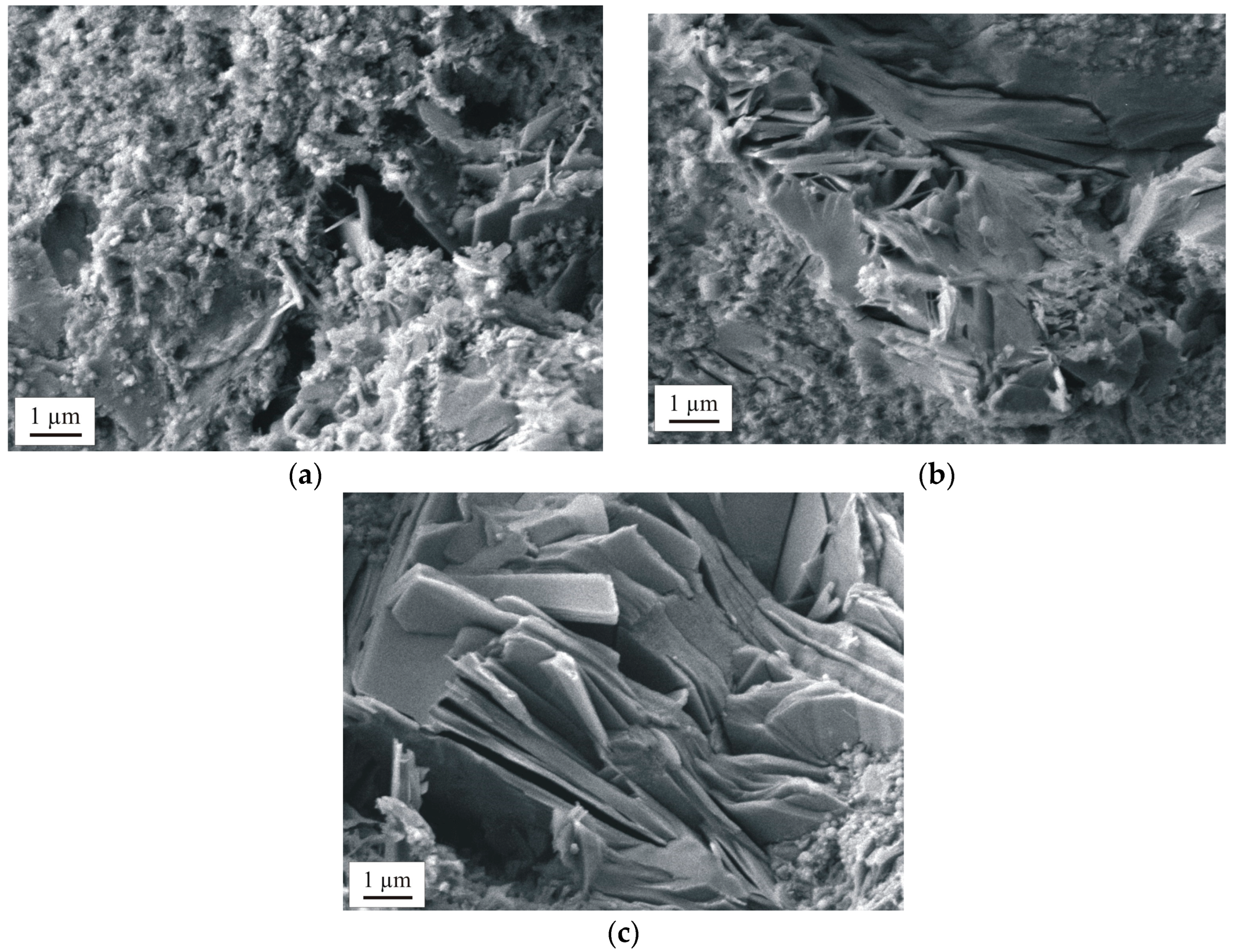
3.2.2. Macrostructure and Microstructure
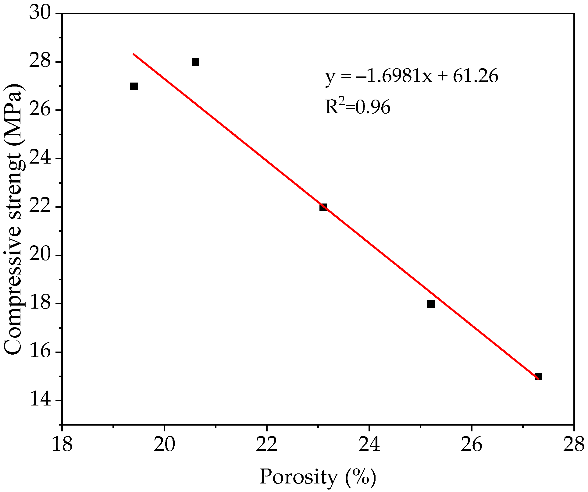
3.2.3. Compressive Strength
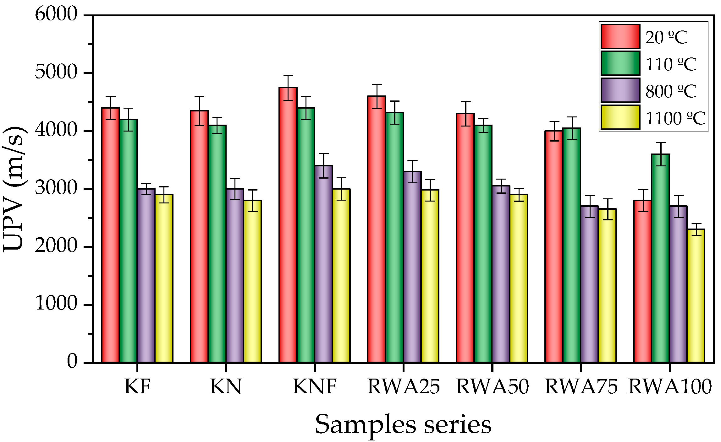
3.2.4. UPV
3.2.5. Shrinkage
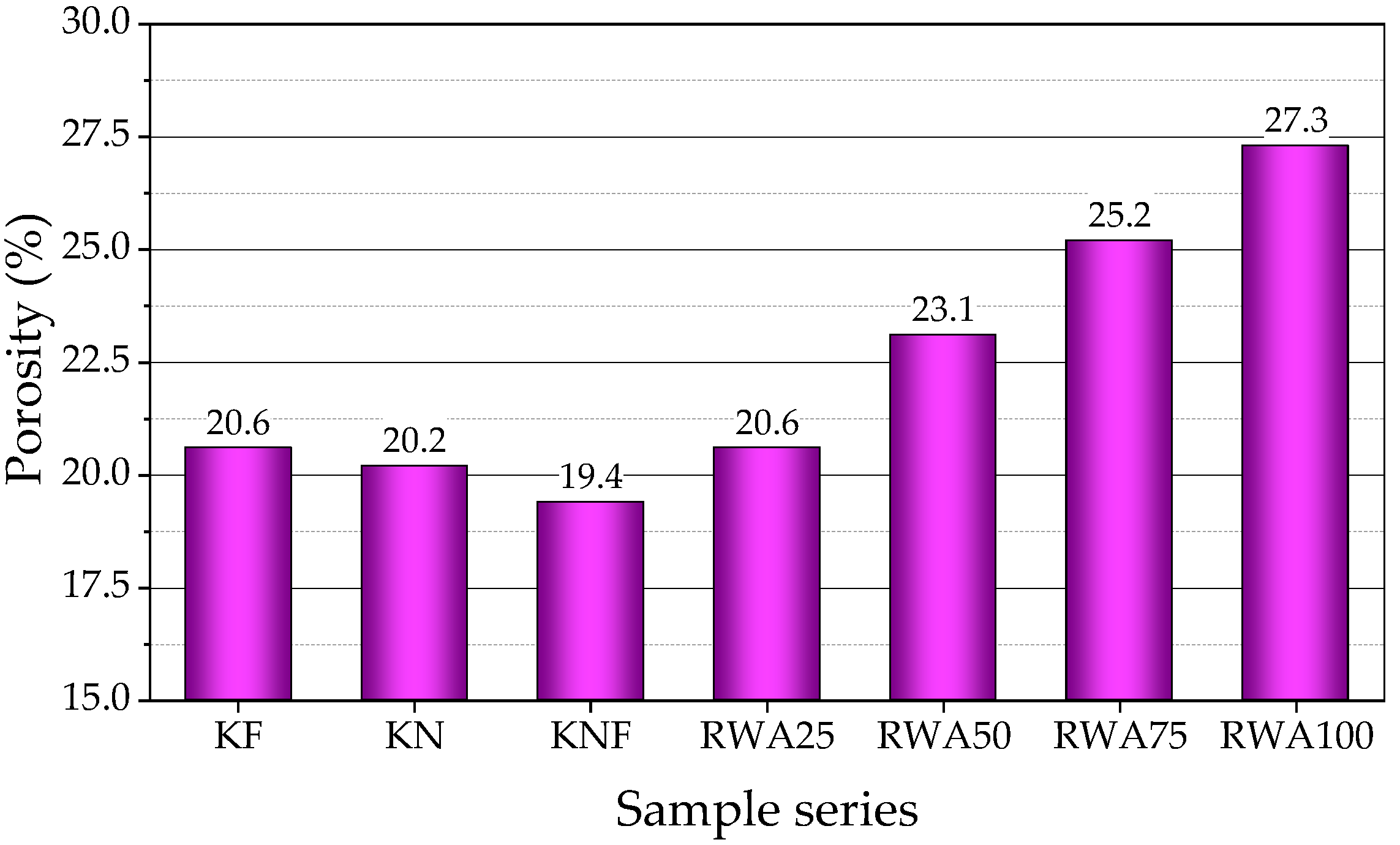
3.2.6. Porosity
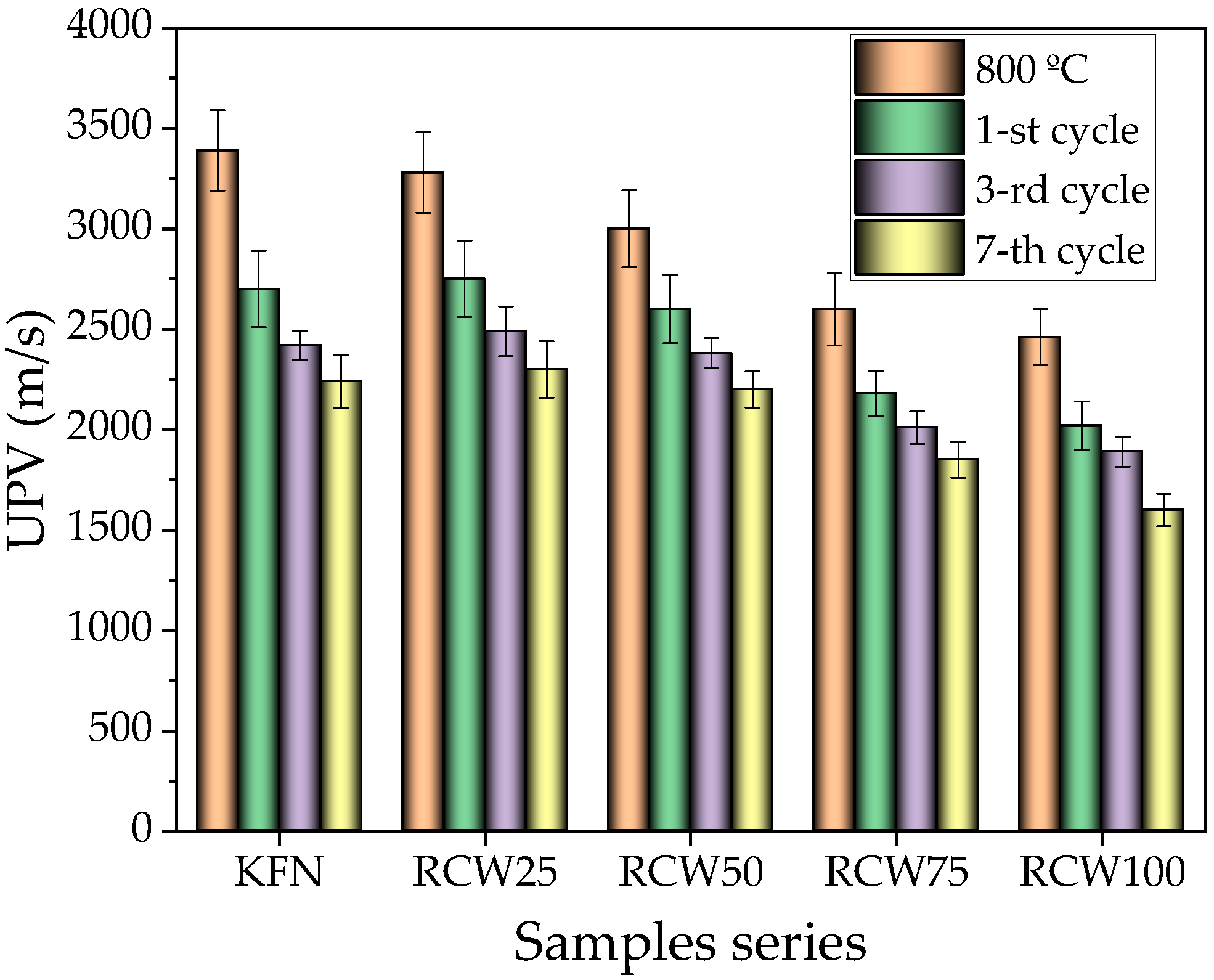
3.2.7. Thermal Shock Resistance
4. Conclusions
Author Contributions
Funding
Institutional Review Board Statement
Informed Consent Statement
Data Availability Statement
Conflicts of Interest
References
- Ahmed, M.M.; Sadoon, A.; Bassuoni, M.T.; Ghazy, A. Utilizing Agricultural Residues from Hot and Cold Climates as Sustainable SCMs for Low-Carbon Concrete. Sustainability 2024, 16, 10715. [Google Scholar] [CrossRef]
- Zhou, Y. Analysis of Zero-Waste City Policy in China: Based on Three-Dimensional Framework. Sustainability 2024, 16, 11027. [Google Scholar] [CrossRef]
- Kim, S.S.; Qudoos, A.; Jakhrani, S.H.; Lee, J.B.; Kim, H.G. Influence of Coarse Aggregates and Silica Fume on the Mechanical Properties, Durability, and Microstructure of Concrete. Materials 2019, 12, 3324. [Google Scholar] [CrossRef] [PubMed]
- Soares, D.; De Brito, J.; Ferreira, J.; Pacheco, J. Use of coarse recycled aggregates from precast concrete rejects: Mechanical and durability performance. Constr. Build. Mater. 2014, 71, 263–272. [Google Scholar] [CrossRef]
- Wang, X.; Deng, C.; Chen, Y.; Wang, J.; Ding, J.; Ma, B.; Zhang, Y.; Wang, Q.; Zhu, H.; Yu, C. Stress–strain behaviour and degradation mechanism of low–carbon MgO–C refractories at 900–1100 °C: Role of TiB2–BN–AlN waste. J. Eur. Ceram. Soc. 2025, 45, 116859. [Google Scholar] [CrossRef]
- Lee, W.E.; Vieira, W.; Zhang, S.; Ghanbari Ahari, K.; Sarpoolaky, H.; Parr, C. Castable refractory concretes. Int. Mater. Rev. 2001, 46, 145–167. [Google Scholar] [CrossRef]
- Sinha, S.; Ghosh, S.; Samanta, A.K. Influence of waste refractory brick on the destructive and non-destructive properties of sustainable eco-friendly concrete. Mater. Today Proc. 2023, in press. [Google Scholar] [CrossRef]
- Seco, A.; Del Castillo, J.M.; Espuelas, S.; Marcelino-Sadaba, S.; Garcia, B. Stabilization of a Clay Soil Using Cementing Material from Spent Refractories and Ground-Granulated Blast Furnace Slag. Sustainability 2021, 13, 3015. [Google Scholar] [CrossRef]
- Ghosh, S.; Samanta, A.K.; Sahandi, A.k. Effect of Elevated Temperature on Diverse Properties of Concrete Containing Waste Materials. Indian J. Eng. Mater. Sci. 2023, 30, 195–211. [Google Scholar] [CrossRef]
- Santos, A.C.P.; Ortiz-Lozano, J.A.; Villegas, N.; Aguado, A. Experimental study about the effects of granular skeleton distribution on the mechanical properties of self-compacting concrete (SCC). Constr. Build. Mater. 2015, 78, 40–49. [Google Scholar] [CrossRef]
- Ducastel, A.; Gueguen, E.; Horckmans, L.; Fricke-Begemann, C.; Connemann, S.; Knapp, H.; Bouillot, F.; Makowe, J.; Stark, A. Innovative separation technologies for refractory waste. In Proceedings of the 14th Biennial Worldwide Unified International Conference on Refractories; John Wiley & Sons, Inc.: Hoboken, NJ, USA, 2015; pp. 1–4. [Google Scholar]
- Horckmans, L.; Nielsen, P.; Dierckx, P.; Ducastel, A. Recycling of refractory bricks used in basic steelmaking: A review. Resour. Conserv. Recycl. 2019, 140, 297–304. [Google Scholar] [CrossRef]
- Fang, C.; Feng, J.; Huang, S.; Hu, J.; Wang, W.; Li, N. Mechanical properties and microscopic characterization of mortar with recycled aggregate from waste road. Case Stud. Constr. Mater. 2022, 17, e01441. [Google Scholar] [CrossRef]
- Simon, F.G.; Adamczyk, B.; Kley, G. Refractory Materials from Waste. Mater. Trans. 2003, 44, 1251–1254. [Google Scholar] [CrossRef]
- Kwong, K.-S.; Bennett, J.P. Recycling practices of spent MgO-C refractories. J. Miner. Mater. Charact. Eng. 2002, 1, 69–78. [Google Scholar] [CrossRef]
- Sua-iam, G.; Makul, N. Rheological and mechanical properties of cement–fly ash self-consolidating concrete incorporating high volumes of alumina-based material as fine aggregate. Constr. Build. Mater. 2015, 95, 736–747. [Google Scholar] [CrossRef]
- Zhang, M.; Zhu, L.; Gao, S.; Dong, Y.; Yuan, H. Mechanical properties of recycled aggregate concrete prepared from waste concrete treated at high temperature. J. Build. Eng. 2023, 76, 107045. [Google Scholar] [CrossRef]
- Nassar, R.U.D.; Balachandra, A.; Soroushian, P. Formulation of high-recycled-content hydraulic cements based on alkali aluminosilicate chemistry and mechanochemical processing techniques. Constr. Build. Mater. 2024, 437, 137017. [Google Scholar] [CrossRef]
- Hanagiri, S.; Matsui, T.; Shimpo, A.; Aso, S.; Inuzuka, T.; Matsuda, T.; Sakaki, S.; Nakagawa, H. Recent Improvement of Recycling Technology for Refractories; 2008; Available online: https://www.nipponsteel.com/en/tech/report/nsc/pdf/n9815.pdf (accessed on 1 December 2024).
- Wang, C.; Liu, J.; Du, H.; Guo, A. Effect of fly ash cenospheres on the microstructure and properties of silica-based composites. Ceram. Int. 2012, 38, 4395–4400. [Google Scholar] [CrossRef]
- Danish, A.; Mosaberpanah, M.A. Formation mechanism and applications of cenospheres: A review. J. Mater. Sci. 2020, 55, 4539–4557. [Google Scholar] [CrossRef]
- Hanif, A.; Diao, S.; Lu, Z.; Fan, T.; Li, Z. Green lightweight cementitious composite incorporating aerogels and fly ash cenospheres—Mechanical and thermal insulating properties. Constr. Build. Mater. 2016, 116, 422–430. [Google Scholar] [CrossRef]
- Zeng, Q.; Li, K. Reaction and microstructure of cement–fly-ash system. Mater. Struct. Constr. 2015, 48, 1703–1716. [Google Scholar] [CrossRef]
- Zhao, J.; Wang, D.; Wang, X.; Liao, S.; Lin, H. Ultrafine grinding of fly ash with grinding aids: Impact on particle characteristics of ultrafine fly ash and properties of blended cement containing ultrafine fly ash. Constr. Build. Mater. 2015, 78, 250–259. [Google Scholar] [CrossRef]
- Hsu, S.; Chi, M.; Huang, R. Effect of fineness and replacement ratio of ground fly ash on properties of blended cement mortar. Constr. Build. Mater. 2018, 176, 250–258. [Google Scholar] [CrossRef]
- Sun, Y.; Lee, H.S. Effect of fly ash with or without mechanical activation on early-age cement hydration: A comparative case study by boundary nucleation and growth model. Thermochim. Acta 2022, 716, 179306. [Google Scholar] [CrossRef]
- Aurich, J.C.; Linke, B.; Hauschild, M.; Carrella, M.; Kirsch, B. Sustainability of abrasive processes. CIRP Ann. 2013, 62, 653–672. [Google Scholar] [CrossRef]
- Fořt, J.; Vejmelková, E.; Koňáková, D.; Alblová, N.; Čáchová, M.; Keppert, M.; Rovnaníková, P.; Černý, R. Application of waste brick powder in alkali activated aluminosilicates: Functional and environmental aspects. J. Clean. Prod. 2018, 194, 714–725. [Google Scholar] [CrossRef]
- Ourgessa, A.W.; Kraxner, J.; Elsayed, H.; Galusek, D.; Bernardo, E. Sustainable construction materials from alkali-activated waste fiberglass and waste refractory. Open Ceram. 2024, 20, 100678. [Google Scholar] [CrossRef]
- EN 14647:2005/AC:2006; Calcium Aluminate Cement—Composition, Specifications and Conformity Criteria. European Committee for Standardization: Brussels, Belgium, 2006.
- EN 1008:2002; Mixing Water for Concrete—Specification for Sampling, Testing and Assessing the Suitability of Water, Including Water Recovered from Processes in the Concrete Industry, as Mixing Water for Concrete. European Committee for Standardization: Brussels, Belgium, 2002.
- Alcoa Calcium Aluminate Cement: Test Methods; Almatis GmbH: Frankfurt, Germany, 1999.
- Pundienė, I.; Pranckevičienė, J.; Zhu, C.; Kligys, M. The role of temperature and activator solution molarity on the viscosity and hard structure formation of geopolymer pastes. Constr. Build. Mater. 2021, 272, 121661. [Google Scholar] [CrossRef]
- EN 1402-6:2003; Unshaped Refractory Products—Part 6: Measurement of Physical Properties. European Committee for Standardization: Brussels, Belgium, 2003.
- Goberis, S. Thermal Stability of Unshaped Refractory Materials. Refract. Ind. Ceram. 2003, 44, 427–430. [Google Scholar] [CrossRef]
- Yao, T.; Wang, Y.; Zhang, W.; Li, M.; Luo, S.; Qi, S. Influence of recycled waste concrete powders on the performances of sulphoaluminate cement. Constr. Build. Mater. 2024, 426, 136226. [Google Scholar] [CrossRef]
- Otroj, S.; Bahrevar, M.A.; Mostarzadeh, F.; Nilforoshan, M.R. The effect of deflocculants on the self-flow characteristics of ultra low-cement castables in Al2O3–SiC–C system. Ceram. Int. 2005, 31, 647–653. [Google Scholar] [CrossRef]
- Hanawa, M.; Kita, Y.; Irisawa, K. Influence of temperature and polyphosphate contents on hydroxyapatite crystallization in calcium aluminate cement modified with sodium polyphosphate. Constr. Build. Mater. 2024, 449, 138503. [Google Scholar] [CrossRef]
- Aboutaleb, D.; Safi, B.; Chahour, K.; Belaid, A. Use of refractory bricks as sand replacement in self-compacting mortar. Cogent Eng. 2017, 4, 1360235. [Google Scholar] [CrossRef]
- Liebscher, M.; Lange, A.; Schröfl, C.; Fuge, R.; Mechtcherine, V.; Plank, J.; Leonhardt, A. Impact of the molecular architecture of polycarboxylate superplasticizers on the dispersion of multi-walled carbon nanotubes in aqueous phase. J. Mater. Sci. 2017, 52, 2296–2307. [Google Scholar] [CrossRef]
- Pundienė, I.; Pranckevičienė, J. The synergistic effect of adding a blend of deflocculants and microsilica on the properties of high temperature resistant lightweight concrete with cenospheres. Constr. Build. Mater. 2020, 230, 116961. [Google Scholar] [CrossRef]
- Li, S.; Wang, J.; Zhao, S.; Cai, W.; Wang, Z.; Wang, S. Effect of surface modification and medium on the rheological properties of silica nanoparticle suspensions. Ceram. Int. 2016, 42, 7767–7773. [Google Scholar] [CrossRef]
- Huang, Z.; Liew, J.Y.R.; Li, W. Evaluation of compressive behavior of ultra-lightweight cement composite after elevated temperature exposure. Constr. Build. Mater. 2017, 148, 579–589. [Google Scholar] [CrossRef]
- Huang, Z.; Padmaja, K.; Li, S.; Liew, J.Y.R. Mechanical properties and microstructure of ultra-lightweight cement composites with fly ash cenospheres after exposure to high temperatures. Constr. Build. Mater. 2018, 164, 760–774. [Google Scholar] [CrossRef]
- Topçu, I.B.; Şengel, S. Properties of concretes produced with waste concrete aggregate. Cem. Concr. Res. 2004, 34, 1307–1312. [Google Scholar] [CrossRef]
- Folino, P.; Xargay, H. Recycled aggregate concrete—Mechanical behavior under uniaxial and triaxial compression. Constr. Build. Mater. 2014, 56, 21–31. [Google Scholar] [CrossRef]
- Pundiene, I.; Pranckeviciene, J.; Kligys, M. Effect of a Mixture of Different Types of Deflocculants on the Structure and Properties of Cement Rock and Castable Refractories. Glas. Ceram. 2017, 74, 295–301. [Google Scholar] [CrossRef]
- Pranckevičienė, J.; Pundienė, I. Lightweight Ceramics with Admixtures of Mineral-Wool Production Waste and Aluminum Silicate Cenospheres of Various Fractions. Glas. Ceram. 2022, 78, 406–411. [Google Scholar] [CrossRef]
- Adams, M.P.; Fu, T.; Cabrera, A.G.; Morales, M.; Ideker, J.H.; Isgor, O.B. Cracking susceptibility of concrete made with coarse recycled concrete aggregates. Constr. Build. Mater. 2016, 102, 802–810. [Google Scholar] [CrossRef]
- Hanif, A.; Parthasarathy, P.; Ma, H.; Fan, T.; Li, Z. Properties improvement of fly ash cenosphere modified cement pastes using nano silica. Cem. Concr. Compos. 2017, 81, 35–48. [Google Scholar] [CrossRef]
- Hommer, H. Interaction of polycarboxylate ether with silica fume. J. Eur. Ceram. Soc. 2009, 29, 1847–1853. [Google Scholar] [CrossRef]
- Zhang, H.; Hu, M.; Cheng, Y.; Li, X.; Zhang, X.; Ying, Y.; Cao, J.; Xia, X.; Zhang, S.; Wei, Z.; et al. Synergistic effect of AMPS-based copolymer retarder and HEDP used for set-regulation of ultra-high temperature (≥200 °C) cementing slurry: Performance and mechanism. Constr. Build. Mater. 2024, 449, 138375. [Google Scholar] [CrossRef]
- Burgos-Montes, O.; Palacios, M.; Rivilla, P.; Puertas, F. Compatibility between superplasticizer admixtures and cements with mineral additions. Constr. Build. Mater. 2012, 31, 300–309. [Google Scholar] [CrossRef]
- Poon, C.S.; Chan, D. The use of recycled aggregate in concrete in Hong Kong. Resour. Conserv. Recycl. 2007, 50, 293–305. [Google Scholar] [CrossRef]
- Matias, D.; Brito, J.d.; Rosa, A.; Pedro, D. Durability of Concrete with Recycled Coarse Aggregates: Influence of Superplasticizers. J. Mater. Civ. Eng. 2013, 26, 06014011. [Google Scholar] [CrossRef]
- Santacruz, I.; De La Torre, Á.G.; Álvarez-Pinazo, G.; Cabeza, A.; Cuesta, A.; Sanz, J.; Aranda, M.A.G. Structure of stratlingite and effect of hydration methodology on microstructure. Adv. Cem. Res. 2016, 28, 13–22. [Google Scholar] [CrossRef]
- Ding, J.; Fu, Y.; Beaudoin, J.J. Strätlingite formation in high alumina cement—Silica fume systems: Significance of sodium ions. Cem. Concr. Res. 1995, 25, 1311–1319. [Google Scholar] [CrossRef]
- Heikal, M.; Radwan, M.M.; Morsy, M.S. Influence of curing temperature on the physico- mechanical, characteristics of calcium aluminate cement with air-cooled slag or water-cooled slag. Ceram. Silikáty 2004, 48, 185–196. [Google Scholar]
- Goetz-Neunhoeffer, F.; Klaus, S.; Neubauer, J. Kinetics of CA and CA2 dissolution determined by QXRD and corresponding enthalpies of reactions. In Proceedings of the Calcium Aliuminates; Fentiman, C., Mangabhai, R., Scrivener, K.L., Eds.; IHS BRE Press: Avignon, France, 2014; pp. 18–21. [Google Scholar]
- Gulec, A. Investigation of the effect of different curing conditions on the mechanical performance of calcium aluminate cement concrete at elevated temperatures. Constr. Build. Mater. 2023, 409, 133920. [Google Scholar] [CrossRef]
- Idrees, M.; Ekincioglu, O.; Sonyal, M.S. Hydration behavior of calcium aluminate cement mortars with mineral admixtures at different curing temperatures. Constr. Build. Mater. 2021, 285, 122839. [Google Scholar] [CrossRef]
- Kou, S.C.; Poon, C.S.; Etxeberria, M. Influence of recycled aggregates on long term mechanical properties and pore size distribution of concrete. Cem. Concr. Compos. 2011, 33, 286–291. [Google Scholar] [CrossRef]
- Pan, C.-N.; Shao, C.-H.; Wong, T.-C.; Lee, Y.-C.; Tseng, Y.-H. Properties evaluation and microstructure analysis of materials with recycling refractory aggregates. In Proceedings of the 14th Biennial Worldwide Unified International Conference on Refractories; 14th Biennial Worldwide Congress, Ed.; Documedias GmbH: Vienna, Austria, 2015; pp. 1–4. [Google Scholar]
- Pundienė, I.; Korjakins, A.; Pranckevičienė, J.; Kligys, M. Effect of silicon carbide aggregate, prepared by different methods, on the properties of refractory concrete with cenospheres. Ceram. Int. 2018, 44, 15944–15953. [Google Scholar] [CrossRef]
- Oumarou, N.; Kocaefe, D.; Kocaefe, Y. Investigation of the refractory bricks used for the flue wall of the horizontal anode baking ring furnace. Ceram. Int. 2016, 42, 18436–18442. [Google Scholar] [CrossRef]
- Domingo-Cabo, A.; Lázaro, C.; López-Gayarre, F.; Serrano-López, M.A.; Serna, P.; Castaño-Tabares, J.O. Creep and shrinkage of recycled aggregate concrete. Constr. Build. Mater. 2009, 23, 2545–2553. [Google Scholar] [CrossRef]
- Antonovič, V.; Stonys, R.; Boris, R.; Malaiškien, J. Effect of quartz sand on the properties and alkali resistance of refractory aluminosilicate castables. Constr. Build. Mater. 2022, 351, 128978. [Google Scholar] [CrossRef]
- Adams, M.P.; Ideker, J.H. Influence of aggregate type on conversion and strength in calcium aluminate cement concrete. Cem. Concr. Res. 2017, 100, 284–296. [Google Scholar] [CrossRef]
- Kerienė, J.; Antonovič, V.; Stonys, R.; Boris, R. The influence of the ageing of calcium aluminate cement on the properties of mortar. Constr. Build. Mater. 2019, 205, 387–397. [Google Scholar] [CrossRef]


| Components | Sample Series | |||||||||
|---|---|---|---|---|---|---|---|---|---|---|
| K1 | K2 | K3 | KF | KN | KFN | RCW25 | RCW50 | RCW75 | RCW100 | |
| Cement | 100 | 100 | 100 | 20 | 20 | 20 | 20 | 20 | 20 | 20 |
| CA | – | – | – | 65 | 65 | 65 | 48 | 32 | 17 | – |
| MCA | – | – | – | 12 | 12 | 12 | 12 | 12 | 12 | 12 |
| RCW | – | – | – | 0 | 0 | 0 | 17 | 33 | 48 | 65 |
| FA | – | – | – | 3 | 3 | 3 | 3 | 3 | 3 | 3 |
| ST * | – | 0.1 | 0.1 | – | 0.1 | 0.1 | 0.1 | 0.1 | 0.1 | 0.1 |
| PCE-20 * | 0.1 | – | 0.1 | 0.1 | – | 0.1 | 0.1 | 0.1 | 0.1 | 0.1 |
| Water * | 11.8 | 11.5 | 10.8 | 11.8 | 11.5 | 10.8 | 10.9 | 11.6 | 12.3 | 13.1 |
Disclaimer/Publisher’s Note: The statements, opinions and data contained in all publications are solely those of the individual author(s) and contributor(s) and not of MDPI and/or the editor(s). MDPI and/or the editor(s) disclaim responsibility for any injury to people or property resulting from any ideas, methods, instructions or products referred to in the content. |
© 2025 by the authors. Licensee MDPI, Basel, Switzerland. This article is an open access article distributed under the terms and conditions of the Creative Commons Attribution (CC BY) license (https://creativecommons.org/licenses/by/4.0/).
Share and Cite
Pranckevičienė, J.; Pundienė, I. Advances in Deflocculant Utilisation in Sustainable Refractory Concrete with Refractory Waste. Sustainability 2025, 17, 669. https://doi.org/10.3390/su17020669
Pranckevičienė J, Pundienė I. Advances in Deflocculant Utilisation in Sustainable Refractory Concrete with Refractory Waste. Sustainability. 2025; 17(2):669. https://doi.org/10.3390/su17020669
Chicago/Turabian StylePranckevičienė, Jolanta, and Ina Pundienė. 2025. "Advances in Deflocculant Utilisation in Sustainable Refractory Concrete with Refractory Waste" Sustainability 17, no. 2: 669. https://doi.org/10.3390/su17020669
APA StylePranckevičienė, J., & Pundienė, I. (2025). Advances in Deflocculant Utilisation in Sustainable Refractory Concrete with Refractory Waste. Sustainability, 17(2), 669. https://doi.org/10.3390/su17020669