Abstract
Seismic isolation systems play a crucial role in enhancing structural resilience during earthquakes, with lead rubber bearings being a widely adopted solution. These bearings incorporate lead cores to effectively dissipate seismic energy. However, their widespread application is constrained by significant drawbacks, including high costs and environmental concerns associated with lead. This study introduces a novel sustainable S-shaped steel damper made from standard steel. The influence of key geometrical parameters—thickness, width, and the distance from the bolt hole to the arc’s start—on the cyclic behavior of the dampers was investigated. Seven prototypes were designed, manufactured, and experimentally tested to evaluate their horizontal stiffness and damping performance. Subsequentially, the experimental results were considered for the validation of a numerical model based on a full 3D Finite Element discretization. The model, calibrated using simple uniaxial steel material tests, facilitates the identification of optimal geometric features for the production of S-shaped steel dampers without the need for extensive prototype fabrication and experimental testing. Additionally, the model can be seamlessly integrated into future numerical structural analyses, enabling a comprehensive evaluation of performance characteristics. In conclusion, this research provides critical insights into the geometric optimization of S-shaped steel dampers as cost-effective and sustainable dissipation devices. It offers both experimental data and a robust numerical model to guide future designs for improved seismic mitigation performances.
1. Introduction
Since the mid-1990s, the implementation of passive energy dissipation devices in seismic engineering has experienced significant growth [1,2,3,4,5,6,7]. This surge is largely attributed to the devices’ ability to minimize earthquake-induced responses in both buildings and bridges. Modern seismic design philosophies prioritize the use of these devices, concentrating damage during seismic events to ensure that the primary structural components remain intact. After an earthquake, these devices can be quickly replaced to restore their energy dissipation capabilities [1,8]. Among these devices, hysteretic steel dampers have garnered particular attention due to their stable hysteretic behavior, achieved through controlled plastic deformation of steel, which provides long-term reliability and resistance to temperature variations.
Hysteretic steel dampers are critical components in seismic engineering, designed to enhance the earthquake resistance of structures by dissipating seismic energy. These devices operate on the principle of hysteresis, where they undergo plastic deformations to absorb and dissipate energy, thereby reducing the seismic forces transmitted to the structural components. This energy dissipation mechanism significantly improves structural resilience and minimizes earthquake-induced damage. Hysteresis steel dampers are valued for their simplicity, cost-effectiveness, and robustness, making them widely applicable in various structural systems, including buildings and bridges. In high seismic-risk countries like Japan, the integration of hysteretic steel dampers has become prevalent [9,10]. These dampers are often used in conjunction with elastomeric bearings [8,11,12,13] to enhance energy dissipation and reduce maximum displacements. This approach is gaining traction as an alternative to conventional isolation devices, such as lead rubber bearings (LRBs), which rely on a lead core for effective energy dissipation. In fact, while effective, lead presents significant drawbacks, including its weight, toxicity, environmental impact, and high cost, which increasingly limit its use in modern engineering practices focused on sustainability. To address these issues, researchers have also explored alternative materials such as shape memory alloys (SMAs) [14]. SMAs, as advanced functional materials, offer unique advantages, including high damping capacity, fatigue resistance, and self-centering capabilities, making them theoretically ideal for seismic applications. However, their high cost and environmental sensitivity have hindered widespread adoption in large-scale projects, creating a gap in the market for cost-effective and environmentally sustainable solutions. In response to these challenges, steel dampers are emerging as a promising and practical solution.
Hysteresis steel dampers come in various shapes, each tailored to specific applications and performance requirements. U-shaped dampers, for instance, are designed for multi-directional deformation and high-energy dissipation [15]. They are often used in base-isolated buildings to control deformation and dissipate energy. These dampers are effective in reducing structural response to seismic activities and are robust and reusable after severe earthquakes [12,13,16,17,18]. Circular hollow steel dampers utilize the geometric elasticity of circular shapes for energy dissipation. Commonly employed in buildings due to their ease of installation and maintenance, these dampers exhibit good fatigue resistance and stable hysteretic behavior under cyclic loads [19]. S-shaped steel plate dampers are constructed from S-shaped plates that transition from flexural to tensile behavior under large displacements. These are particularly useful in seismic resilient applications requiring high deformation capacity. They are known for their large deformation, ductility, and stable hysteresis loops under cyclic loading [20]. Shear panel dampers dissipate energy through the metallic deformation of shear panels and are utilized to minimize damage to major structural components. The use of low-yield strength steel in these dampers results in high ductility and energy dissipation capacity [21,22]. Steel strip dampers, available in various shapes like dumbbell, tapered, and hourglass [23,24], are designed to reduce stress concentration and enhance seismic performance. These dampers provide high dissipation capacity through controlled deformation, making them flexible and effective in seismic energy dissipation systems [24]. X-shaped dampers provide lateral resistance and energy dissipation initially through the flexural bending of pipe plates and later through tensile stretching at composite pipe halves. These dampers present stable and robust hysteretic loops after yielding, offering strength and deformation capacity under fatigue loads. However, the welding methods and pipe configurations significantly influence their stiffness, strength, ductility, and energy absorption efficiency. Welded connections can affect plasticity development and deformation abilities, often leading to early fracture failure at the weld or fatigue failure at heat-affected zones. To overcome these limitations, bolted connections are sometimes used, offering better dynamic response control performance under both medium- and high-intensity earthquakes [25,26]. J-shaped dampers are known for their high ductility and energy absorption capabilities. Numerical and experimental studies have shown that J-shaped dampers can accumulate effective plastic strains after cyclic loading, effectively absorbing most earthquake energy [27,28].
Alongside the shape of the devices and the material, the dimensions of the geometric parameters can result in a final device with different seismic mitigation properties. Optimizing these parameters is crucial for enhancing their performance in seismic applications. These parameters directly influence the dampers’ stiffness, yield strength, energy dissipation, and ductility. Increasing the straight section length and end arc radius can reduce the horizontal stiffness, while increasing the thickness and width can increase it [29]. Numerical studies have shown that increasing the thickness and width of the U-shaped steel damper enhances its energy dissipation and stiffness. This optimization can significantly improve the damper’s performance under cyclic loading [30]. Though a fiber-reinforced elastomeric isolator could be applied in practice [31,32], the steel damper could also be coupled with an elastomeric isolator to form a novel system and supply energy dissipation capacity [33,34]. According to the experimental study developed in [35], the end of the straight part should be strengthened (for example, by increasing its width) to avoid the concentration of plastic strain and the unrecoverable deformation of the U-shaped damper. The height–thickness ratio is crucial for the damper’s stiffness and ductility. Parametric studies reveal that increasing the height–thickness ratio enhances the energy dissipation capacity and ductility of the damper [20]. Optimizing the geometrical parameters of steel dampers, including height, width, thickness, and curvature, enhances their performance in seismic applications. These optimizations lead to improved energy dissipation, stability, and ductility, making them effective for mitigating structural vibrations during earthquakes.
This research investigates the influence of the geometrical characteristics of an S-shaped steel damper. Initially, the impact of geometrical features on the lateral behavior of these dampers is investigated experimentally. Subsequently, a numerical model is proposed and validated for its use in the preliminary design phase, allowing the hypothesis and investigation of various geometrical features to achieve an optimal design. This model is also validated for future structural applications. The paper is structured into three sections: an experimental investigation of both the steel material and the dampers, a focus on the numerical model, and finally, conclusions and discussion.
2. Experimental Investigation
2.1. Material Properties
Uniaxial tensile tests were performed to evaluate the properties of the steel material according to ISO 6892 [36]. Three dog-bone specimens of steel were tested in a uniaxial tensile testing machine. The tests were performed in a displacement-controlled manner, and the load were monitored by load cells. By increasing the load, as expected, the specimen started to deform elastically, then exhibiting plastic deformation, late necking, and ultimately fracturing (Figure 1). The strain measurements presented here were obtained using the clamped extensometer device shown in Figure 1b, while strain gauges (Figure 1c) were employed in selected tests for validation purposes. The obtained stress (σ)—strain (ε) curves are shown in Figure 2. From these tests, it is possible to deduce Young’s modulus , yield strength , ultimate strength , and the maximum elongation of the steel.
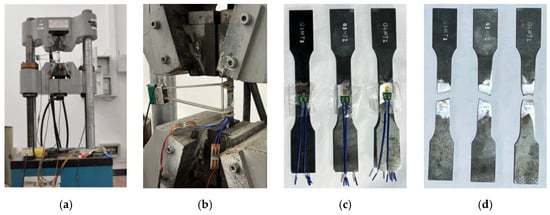
Figure 1.
Uniaxial tensile test: testing machine (a) and specimens during (b), before (c), and after (d) the test.
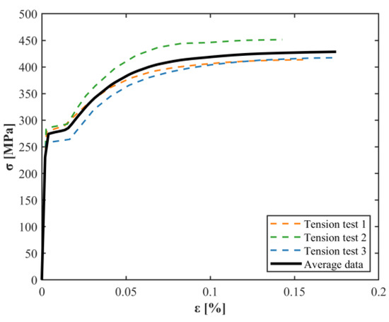
Figure 2.
Stress–strain curves obtained experimentally for the uniaxial tensile test.
The results, evaluated as the average values of the three specimens, show that the steel then used to assemble the S-shaped dampers has Young’s modulus equal to about 190 GPa, a yield strength equal to 273 MPa, an ultimate strength equal to 427 MPa, and a maximum elongation equal to 16% (Table 1). Note that these material properties were considered in the Finite Element (FE) analyses performed in the next section (Section 3.1).

Table 1.
Results of the uniaxial tensional tests.
2.2. Quasi-Static Cyclic Shear Test
2.2.1. Specimen Design
Once the material was characterized, tests were performed on the final S-shaped steel dampers. As mentioned before, the final aim of the research is to investigate the influence of the geometric properties on the final lateral behavior of the devices. With this purpose, seven different specimens were designed and produced. In Figure 3 and Table 2, the dampers with the different geometrical properties are shown.
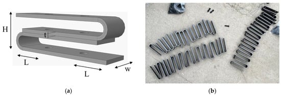
Figure 3.
S-shaped steel dampers: geometric properties (a) and prototypes produced (b).
Table 2.
Designed details of S-shaped steel dampers.
The final damper is obtained from the bonding of two long U-shaped steel dampers. Two bolts are used for their connection in the central part. Thickness (), width (), height (), and length (), evaluated as the distance between the bolt and the arc end, are the important geometrical features of the dampers and can influence the final mechanical properties. For this reason, the authors proposed seven different S-shaped steel damper designs to investigate the influence of the geometrical parameters on their final lateral behavior.
In particular, the first specimen, S1, has a thickness of 2 mm, a width of 40 mm, and a height of 52 mm, and the distance of the bolts from the start of the arc of the S-shaped steel damper is equal to 10.5 mm. Specimens S2 and S3 share the same width, height, and length as the first specimen but vary in thickness. Respectively, it is equal to 3 and 4 mm. Instead, S4 and S5 share the same thickness, height, and length of S1, but vary in width. In particular, it is equal to 35 and 30 mm, respectively, for S4 and S5. Then, specimens S6 and S7 share the same thickness, width, and height as S1, but vary in the final distance of the bolts from the start of the semicircle arc. It is equal to 14.5 and 6.5 mm, respectively, for S6 and S7.
Note that these dampers were designed by the authors for implementation in a final seismic isolator device, which consists of an elastomeric seismic isolator with S-shaped dampers on the sides. Consequently, the height is set at 52 mm and remains constant across the models.
2.2.2. Experimental Tests
The testing machine implemented is an Instron 8801 (Figure 4a). A transmission device was designed and produced in order to adapt the geometric part of the S-shaped steel dampers to the testing machine (Figure 4b). Quasi-static cyclic shear tests were performed at a speed of 0.1 mm/s. In particular, the dampers were subjected to cyclic horizontal displacements, starting with an amplitude of 2.42 mm up to a final amplitude of 50 mm (Figure 4c) based on FEMA 461 [37]. For each amplitude, two cycles were performed. The results were evaluated in terms of horizontal stiffness and damping ratio according to Equations (1)–(3) (for further details, the reader is referred to [38]):
where is the effective horizontal stiffness; and are the maximum and minimum horizontal forces obtained under each side of the loading cycle, respectively; and are the maximum and minimum vertical displacements obtained under each side of the loading cycle, respectively; is the dissipated energy in each cycle, which is equal to the area inside the force–displacement hysteresis curve; and is the stored energy. In Equation (3), is equal to the average of the absolute value displacement of and . Note that the evaluation was conducted solely for the last cycle, where the maximum displacement was achieved. In Table 3, the experimental results are summarized.
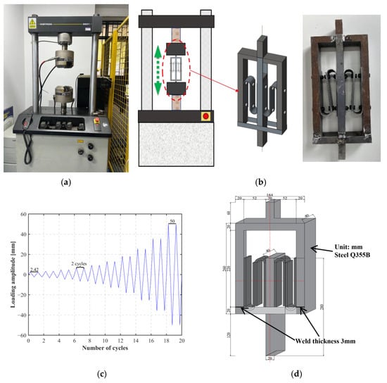
Figure 4.
Cyclic shear test: testing machine (a), loading setup and transmission device (b), loading protocol (c), and design of the shear frame (d).
Table 3.
Experimental data for S-shaped steel dampers.
The resulting displacement versus horizontal force curves are shown in Figure 5. Due to the unavoidable intrinsic geometric limitations of the transmission device, during some tests, contact occurred between the bolts of the steel dampers. This issue pertains specifically to the transmission device used in this uniaxial tensile test and does not occur when these devices are implemented in seismic isolation systems. Therefore, it is not representative of the actual lateral behavior of the dampers. So, filtered data were produced post-processing in order to eliminate such imperfections in the final curve (Figure 5). The filtered curves were considered for the evaluation of both horizontal stiffness and the damping ratio.
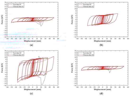
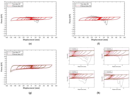
Figure 5.
Experimental results obtained for the SSSDs in the cyclic tests: S1 (a), S2 (b), S3 (c), S4 (d), S5 (e), S6 (f), S7 (g), and zoomed details of S1, S4, S5, and S6 (h).
Based on the results obtained, specimens S2 and S3 exhibited significantly higher horizontal stiffness compared to the others. This higher stiffness can be attributed to their increased thickness. A thicker specimen generally offers greater resistance to horizontal forces, leading to higher stiffness values. The damping ratio remained almost the same between the models, with a value of around 0.40.
The width variation had the same effect. In fact, by increasing the width, the final horizontal stiffness also increased. Specimen S1, with a higher width equal to 40 mm, showed a horizontal stiffness equal to 47.06 N/mm, while specimen S5, with a width equal to 30 mm, showed a horizontal stiffness equal to 33.81 N/mm, with a reduction of more than 20%. Also, in this case, the damping ratio was not affected by the change in the geometrical feature.
As for the distance between the bolt hole and the beginning of the arc, specimen S7, which had the smallest L, exhibited both higher horizontal stiffness and a higher damping ratio. Notably, S7 showed an abnormal increase in the damping ratio compared to other specimens, whose values averaged approximately 0.40 ± 5%. Specifically, S7 recorded a damping ratio of 0.44, characterized by asymmetric and unstable hysteretic behavior in both positive and negative directions of the force–displacement curve, as shown in Figure 5g. This behavior is attributed to the deformation of the bolt holes. In fact, the reduced distance between the hole and the arc increases sensitivity to deformation. This phenomenon is even more clear in Figure 6, which highlights the damages observed after testing (Figure 6a) and the deformations at maximum shear strain (Figure 6b) for all the specimens. Specimen S7 exhibited significant deformation around the bolt hole and arc end regions. Conversely, specimen S6, with a larger distance L, showed minimal deformation of the holes. Specimens S2 and S3, which featured greater thickness, experienced a stiffer deformation and a brittle failure, with the dampers fracturing during the 18th and 19th loading cycles. In the end, specimens S4 and S5, which featured increased width, exhibited post-test behavior similar to that of specimens S1 and S6, with only minor deformation of the bolt holes. This consistency was also observed in their deformation at maximum displacement.
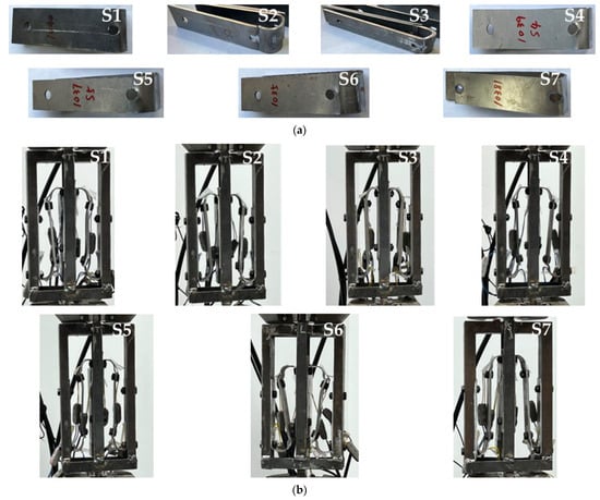
Figure 6.
Damages observed at the end of the experimental cyclic shear tests (a) and deformations at the maximum displacement (b).
3. Numerical Investigation
3.1. Finite Element Model
The experimental cyclic shear tests were modeled and analyzed numerically. In particular, steel damper specimens and transmission devices were modeled in Abaqus [39]. According to the symmetric condition of the steel damper, only one-half of the device, including one S-shaped steel damper and transmission part, was modeled to reduce the computational cost.
The S-shaped steel dampers were modeled using a 3D-stress 8-node non-linear solid element (C3D8R), as shown in Figure 7. In the numerical simulation, both material plasticity and geometric nonlinearity were considered. Because of no obvious plastic deformation of the bolts and of the transmission device, elastic material with Young’s modulus of 206 GPa and a Poisson ratio of 0.3 was adopted for these elements. The tested material properties shown in Table 1 were employed for S-shaped elements, and the Poisson ratio was selected to be 0.3. A hard contact with a a 0.3 coefficient of friction was adopted between the surfaces of the bolts, the S-shaped steel dampers, and the transmission device. It should be noted that although the contact was modeled, no actual contact was observed in the numerical simulations due to the idealized geometries of the specimens used, which differ from those in the experimental setup. For the simulations, the same loading patterns indicated in Section 2.2.2 were applied to the FE models.
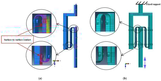
Figure 7.
Numerical model of ½ of an SSSD specimen: 3D assembly (a) and final mesh (b).
3.2. Results
The results were always evaluated in terms of horizontal stiffness and damping ratio for the last cycle at the maximum displacement. These numerical results were subsequently compared with the experimental ones, and the error was evaluated. Figure 8 and Table 4 show the comparison between the experimental and numerical results. In the numerical case, no filtered data were needed to be calculated because no contact between the bolts occurred.
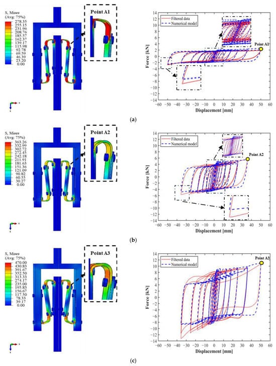
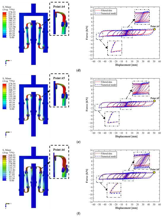
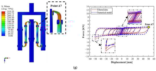
Figure 8.
Comparison between numerical and experimental cyclic curves and FE deformation and stress distribution at maximum displacement: S1 (a), S2 (b), S3 (c), S4 (d), S5 (e), S6 (f), and S7 (g).
Table 4.
Geometric parameters of S-shaped steel dampers.
According to the comparison, the maximum error obtained was found to be equal to a maximum of ±15%, with an absolute average error of 11.29% for the horizontal stiffness and 4.69% for the damping ratio. In detail, the numerical model was able to capture the influence of the geometrical parameters on the final lateral behavior of the S-shaped steel dampers. In fact, as observed during the experimental tests, the increase in thickness led to an increase in horizontal stiffness, the decrease in width resulted in a decrease in horizontal stiffness, and in the end, the decrease in resulted in an increase in horizontal stiffness. For the damping ratio, the numerical results resulted in greater damping than did the experimental ones. However, overall, it can be considered almost constant between the different models with an oscillation of ±5%, reflecting the actual behavior observed during the experimental data.
The deformation and stress distributions of the steel dampers at the maximum displacement during testing (Points A1–A7), as shown in Figure 8, highlight the capability of the numerical model to accurately replicate the actual behavior of the steel dampers, particularly in capturing stress concentrations around the bolt holes and arc regions. Specimens S2 and S3 exhibited higher stress levels due to their stiffer response, while specimen S7 displayed noticeable stress in the arc, emphasizing its increased sensitivity caused by the small distance L. In contrast, specimens S1, S4, S5, and S6 showed very similar deformation patterns and stress distributions, aligning closely with the experimental results.
4. Conclusions and Discussion
In this paper, the influence of the primary geometrical properties of S-shaped steel dampers on their lateral behavior is examined in detail. An experimental campaign is conducted on seven different specimens varying in thickness, width, and the distance between the bolt and the start of the arch’s curve. Subsequently, an FE analysis is performed based on the experimental results to validate the model. The following conclusions can be drawn from the presented results:
- The horizontal stiffness increases with the increase in the thickness and width of the steel dampers and the decrease in the distance between the bolt and the beginning of the arc of the S-shaped steel dampers.
- The damping ratio is not significantly affected by variations in the thickness and width parameters. However, the distance between the bolt and the arc has a notable impact on damping performance. A smaller distance increases the steel dampers’ sensitivity to stress, as the reduced spacing amplifies the stress distributions around the bolt holes and arc end regions. This enhanced sensitivity leads to a significant increase in the damping ratio.
- The FE model, with a mean average absolute error equal to 11.29% for the horizontal stiffness and 4.69% for the damping ratio, is able to capture the influence of the different geometrical properties on the final lateral behavior of the device. So, it can be used both for preliminary design and for FE structural analyses.
As mentioned in Section 2, the S-shaped steel dampers proposed in this research will be integrated into a final seismic isolation device consisting of an elastomeric seismic isolator and two S-shaped steel dampers on the sides. This configuration will provide the energy dissipation capacity of the dampers and the vertical and lateral stiffness of the elastomeric isolators, as well as the recentering capability of the latter. Based on the results obtained, it is evident that high horizontal stiffness is not the goal for these dampers, as it would alter the final horizontal stiffness of the seismic isolation system. Based on the experimental results, specimen S1, with the lower horizontal stiffness, is selected for the production of the final device, which will be the subject of future work, where the final device will be characterized.
In conclusion, this preliminary study provides a deep insight into the characterization and performance of S-shaped steel dampers, which are considered to be innovative, low-cost, and sustainable energy dissipation devices for seismic isolation systems. Through detailed FE analysis and experimental validation, the study demonstrates the potential of such dampers to achieve high hysteresis and symmetric energy dissipation while at the same time maintaining economic feasibility and environmental sustainability. Additionally, with the aim of expediting the design, hence avoiding new experimental characterizations on several prototypes, the FE procedure serves as a digital twin to optimize the performance in different engineering applications.
Author Contributions
Conceptualization, K.G. and G.M.; methodology, K.G. and G.M.; software, K.G.; validation, K.G., G.P., P.P. and G.M.; formal analysis, K.G. and G.P.; investigation, K.G. and G.P.; resources, K.G., P.P. and G.M.; data curation, K.G.; writing—original draft preparation, K.G. and G.P.; writing—review and editing, K.G., G.P., P.P. and G.M.; visualization, K.G., G.P., P.P. and G.M.; supervision, P.P. and G.M.; project administration, K.G.; funding acquisition, K.G. All authors have read and agreed to the published version of the manuscript.
Funding
This research received no external funding.
Institutional Review Board Statement
Not applicable.
Informed Consent Statement
Not applicable.
Data Availability Statement
The raw data are available on request via email.
Acknowledgments
The author Kai Guo would like to acknowledge the financial support of the China Scholarship Council (CSC) for his PhD program.
Conflicts of Interest
The authors declare no conflicts of interest.
References
- Soong, T.T.; Spencer, B.F. Supplemental Energy Dissipation: State-of-the-Art and State-of-the-Practice. Eng. Struct. 2002, 24, 243–259. [Google Scholar] [CrossRef]
- Esfahani, A.N.; Zareei, S.A.; Birzhandi, M.S.; Zafarani, M.M. Experimental and Numerical Study of the Centripetal Behavior of the Divergent Bracing Frame Equipped with Rotational Friction Damper and Shape Memory Bolts. Constr. Build. Mater. 2024, 438, 137245. [Google Scholar] [CrossRef]
- He, Z.; Shi, F.; Lin, Z.; Zhang, C.; Zhou, Y.; Zhao, F. Experimental Characterization on Cyclic Stability Behavior of a High-Damping Viscoelastic Damper. Constr. Build. Mater. 2023, 371, 130749. [Google Scholar] [CrossRef]
- Koutsoloukas, L.; Nikitas, N.; Aristidou, P. Passive, Semi-Active, Active and Hybrid Mass Dampers: A Literature Review with Associated Applications on Building-like Structures. Dev. Built Environ. 2022, 12, 100094. [Google Scholar] [CrossRef]
- Kelly, J.M.; Skinner, R.I.; Heine, A.J. Mechanisms of Energy Absorption in Special Devices for Use in Earthquake Resistant Structures. Bull. N. Z. Soc. Earthq. Eng. 1972, 5, 63–88. [Google Scholar] [CrossRef]
- Zeng, C.; Liu, L.; Hu, Y.; Zhao, W.; Xin, X.; Liu, Y.; Leng, J. Stair-Stepping Mechanical Metamaterials with Programmable Load Plateaus. Adv. Funct. Mater. 2024, 34, 2408887. [Google Scholar] [CrossRef]
- Chong, X.; Wu, Z.; Li, F. Vibration Isolation Properties of the Non-linear X-Combined Structure with a High-Static and Low-Dynamic Stiffness: Theory and Experiment. Mech. Syst. Signal Process. 2022, 179, 109352. [Google Scholar] [CrossRef]
- Nguyen, X.D.; Guizani, L. Analytical and Numerical Investigation of Natural Rubber Bearings Incorporating U-Shaped Dampers Behaviour for Seismic Isolation. Eng. Struct. 2021, 243, 112647. [Google Scholar] [CrossRef]
- Kishiki, S.; Zheng, H.; Ishida, T.; Tatsumi, N.; Watanabe, A. Inspection of U-Shaped Steel Dampers Based on Residual Plastic Deformation. Eng. Struct. 2021, 245, 112915. [Google Scholar] [CrossRef]
- Apostolidi, E.; Dritsos, S.; Giarlelis, C.; Jara, J.; Sutcu, F.; Takeuchi, T.; White, J. Seismic Isolation and Response Control; International Association for Bridge and Structural Engineering (IABSE): Zurich, Switzerland, 2021. [Google Scholar]
- Ene, D.; Yamada, S.; Jiao, Y.; Kishiki, S.; Konishi, Y. Reliability of U-Shaped Steel Dampers Used in Base-Isolated Structures Subjected to Biaxial Excitation. Earthq. Eng. Struct. Dyn. 2017, 46, 621–639. [Google Scholar] [CrossRef]
- Oh, S.H.; Song, S.H.; Lee, S.H.; Kim, H.J. Experimental Study of Seismic Performance of Base-Isolated Frames with U-Shaped Hysteretic Energy-Dissipating Devices. Eng. Struct. 2013, 56, 2014–2027. [Google Scholar] [CrossRef]
- Oh, S.H.; Song, S.H.; Lee, S.H.; Kim, H.J. Seismic Response of Base Isolating Systems with U-Shaped Hysteretic Dampers. Int. J. Steel Struct. 2012, 12, 285–298. [Google Scholar] [CrossRef]
- Song, G.; Ma, N.; Li, H.-N. Applications of Shape Memory Alloys in Civil Structures. Eng. Struct. 2006, 28, 1266–1274. [Google Scholar] [CrossRef]
- Deng, K.; Liang, H.; Yi, Y.; Zhao, C.; Dai, S.; Wu, D. Sliding U-Shaped Steel Damper for Multi-Directional Displacement. Int. J. Non-Linear Mech. 2023, 156, 104483. [Google Scholar] [CrossRef]
- Xie, X.; Chen, S.X.; Zhou, X. A Simplified Analytical Model for U-Shaped Steel Dampers Considering Horizontal Bidirectional Deformation. Bull. Earthq. Eng. 2018, 16, 6243–6268. [Google Scholar] [CrossRef]
- Qu, B.; Dai, C.; Qiu, J.; Hou, H.; Qiu, C. Testing of Seismic Dampers with Replaceable U-Shaped Steel Plates. Eng. Struct. 2019, 179, 625–639. [Google Scholar] [CrossRef]
- Hui, Y.X.; Li, L.S.; Cheng, H.; Zhang, Y.J.; Wang, D.S. Seismic Mitigation of Continuous Girder Bridges Equipped with U-Shaped Stainless Steel Dampers under near-Fault Earthquake Excitations. Structures 2023, 58, 105597. [Google Scholar] [CrossRef]
- Abebe, D.Y.; Kim, J.W.; Gwak, G.; Choi, J.H. Low-Cycled Hysteresis Characteristics of Circular Hollow Steel Damper Subjected to Inelastic Behavior. Int. J. Steel Struct. 2019, 19, 157–167. [Google Scholar] [CrossRef]
- Zhai, Z.; Guo, W.; Yu, Z.; He, C.; Zeng, Z. Experimental and Numerical Study of S-Shaped Steel Plate Damper for Seismic Resilient Application. Eng. Struct. 2020, 221, 111006. [Google Scholar] [CrossRef]
- Abebe, D.Y.; Jeong, S.J.; Getahune, B.M.; Segu, D.Z.; Choi, J.H. Hysteretic Characteristics of Shear Panel Damper Made of Low Yield Point Steel. Mater. Res. Innov. 2015, 19, S5-902–S5-910. [Google Scholar] [CrossRef]
- Choi, J.; Abebe, D.Y. Hysteresis Characteristics of Shear Panel Damper Using SLY120. APCBEE Procedia 2014, 9, 370–375. [Google Scholar] [CrossRef]
- Suzuki, T.; Motomura, S.; Kinoshita, T.; Inoue, Y.; Kushibe, A.; Iida, T. Shape Optimization of Hourglass-Shaped Damper Using Fe-Mn-Si-Based Alloy Considering Target Load-Displacement Relationship and Target Fatigue Characteristics. Constr. Build. Mater. 2023, 366, 130091. [Google Scholar] [CrossRef]
- Lee, C.H.; Ju, Y.K.; Min, J.K.; Lho, S.H.; Kim, S.D. Non-Uniform Steel Strip Dampers Subjected to Cyclic Loadings. Eng. Struct. 2015, 99, 192–204. [Google Scholar] [CrossRef]
- Guo, W.; Wang, X.; Yu, Y.; Chen, X.; Li, S.; Fang, W.; Zeng, C.; Wang, Y.; Bu, D. Experimental Study of a Steel Damper with X-Shaped Welded Pipe Halves. J. Constr. Steel Res. 2020, 170, 106087. [Google Scholar] [CrossRef]
- Guo, W.; Chen, X.; Yu, Y.; Bu, D.; Li, S.; Fang, W.; Wang, X.; Zeng, C.; Wang, Y. Development and Seismic Performance of Bolted Steel Dampers with X-Shaped Pipe Halves. Eng. Struct. 2021, 239, 112327. [Google Scholar] [CrossRef]
- Kato, S.; Kim, Y.B.; Nakazawa, S.; Ohya, T. Simulation of the Cyclic Behavior of J-Shaped Steel Hysteresis Devices and Study on the Efficiency for Reducing Earthquake Responses of Space Structures. J. Constr. Steel Res. 2005, 61, 1457–1473. [Google Scholar] [CrossRef]
- Kato, S.; Kim, Y.B. A Finite Element Parametric Study on the Mechanical Properties of J-Shaped Steel Hysteresis Devices. J. Constr. Steel Res. 2006, 62, 802–811. [Google Scholar] [CrossRef]
- Gao, J.; Xi, J.; Xu, Y.; Ding, J.; Zhu, J.; Chang, Y.; Chen, B. Analysis of the Mechanical Properties and Parameter Sensitivity of a U-Shaped Steel Damper. Front. Mater. 2021, 8, 713221. [Google Scholar] [CrossRef]
- Satria, E.; Son, L.; Bur, M.; Akbar, M.D. Finite Element Analysis to Determine Stiffness, Strength, and Energy Dissipation of U-Shaped Steel Damper under Quasi-Static Loading. Int. J. Automot. Mech. Eng. 2021, 18, 9042–9050. [Google Scholar] [CrossRef]
- Pianese, G.; van Engelen, N.; Toopchi-Nezhad, H.; Milani, G. High-Damping Fiber-Reinforced Elastomeric Seismic Isolator in Different Boundary Conditions: An Experimental Insight. Eng. Struct. 2024, 300, 117199. [Google Scholar] [CrossRef]
- Pianese, G.; van Engelen, N.; Tait, M.; Milani, G. Shake Table Tests on a Rigid Block Isolated with High-Damping Unbonded Fiber-Reinforced Elastomeric Isolators. Structures 2024, 64, 106595. [Google Scholar] [CrossRef]
- Sheikhi, J.; Fathi, M.; Rahnavard, R. Natural Rubber Bearing Incorporated with High Toughness Steel Ring Dampers. Structures 2020, 24, 107–123. [Google Scholar] [CrossRef]
- Sheikhi, J.; Fathi, M.; Rahnavard, R.; Napolitano, R. Numerical Analysis of Natural Rubber Bearing Equipped with Steel and Shape Memory Alloys Dampers. Structures 2021, 32, 1839–1855. [Google Scholar] [CrossRef]
- Deng, K.; Pan, P.; Su, Y.; Xue, Y. Shape Optimization of U-Shaped Damper for Improving Its Bi-Directional Performance under Cyclic Loading. Eng. Struct. 2015, 93, 27–35. [Google Scholar] [CrossRef]
- ISO 6892-1; Metallic Materials-Tensile Testing-Part 1: Method of Test at Room Temperature. International Organization for Standardization: Geneva, Switzerland, 2009.
- U.S. Department of Homeland Security; Federal Emergency Management Agency. Interim Testing Protocols for Determining the Seismic Performance Characteristics of Structural and Nonstructural Components: FEMA 461/June 2007; Createspace Independent Publishing Platform: Scotts Valley, CA, USA, 2013; ISBN 978-1-4840-1948-1.
- Applied Technology Council. NEHRP Guidelines for the Seismic Rehabilitation of Buildings: FEMA 273; Federal Emergency Management Agency: Washington, DC, USA, 1997.
- Smith, M. ABAQUS/Standard User’s Manual, Version 6.14; Dassault Systèmes: Waltham, MA, USA, 2014. [Google Scholar]
Disclaimer/Publisher’s Note: The statements, opinions and data contained in all publications are solely those of the individual author(s) and contributor(s) and not of MDPI and/or the editor(s). MDPI and/or the editor(s) disclaim responsibility for any injury to people or property resulting from any ideas, methods, instructions or products referred to in the content. |
© 2025 by the authors. Licensee MDPI, Basel, Switzerland. This article is an open access article distributed under the terms and conditions of the Creative Commons Attribution (CC BY) license (https://creativecommons.org/licenses/by/4.0/).