Abstract
The concept behind this undertaking was to create environmentally friendly and sustainable air-conditioning systems supported by energy storage units, as well as to conduct comparative calculations of investment and operational costs to assess their economic viability. In order to meet sustainability requirements, detailed analysis was followed by a decision to utilise cold storage units in which energy is stored through the phase change of water into ice. Aiming to achieve high efficiency, strong reliability and enhanced operational dynamics, a multi-circuit model for coolant flow was developed, incorporating a variable-speed compressor drive. High functionality and performance were attained through the introduction of container vibrations, which resulted in the formation of ice slurry particles in spherical containers placed within an aqueous glycol solution serving as the heat exchange medium. The concept of this technology, along with its accompanying mathematical models, was validated, and the results of this work are presented in the article. To evaluate the competitiveness of air-conditioning systems, the developed solution based on cold storage technology is compared with a lithium-ion battery system and a conventional configuration powered directly by the grid. The results demonstrate that the cold-storage-based air-conditioning system outperforms both reference systems in terms of energy efficiency. An analysis of the full operational cycle indicates that the proposed solution consumes significantly less energy than systems using lithium-ion battery storage. The investment costs are almost twenty percent lower, while service, maintenance and disposal expenses are negligible. These attributes make it a competitive solution that is both economically and environmentally sustainable. In summary, the proposed technology fully satisfies the key principles of sustainability. It does not deplete natural resources, minimises the environmental impact, offers long-term reliability and contributes to lower energy bills and more responsible resource use.
1. Introduction
This article introduces a novel concept for a cold storage system, focusing on its properties, technological parameters and mathematical model. In addition, it presents a comparative analysis of the energy efficiency of an air-conditioning system incorporating cold storage versus two reference configurations: one using lithium-ion (Li-ion) batteries and another powered directly by the electrical grid. The foundation of this initiative to explore alternative air-conditioning configurations, as opposed to systems powered by electricity from energy storage batteries, was the pursuit of sustainable solutions aimed at minimising the environmental impact while ensuring investment viability and operational cost efficiency.
A key drawback of conventional air-conditioning (AC) systems is their inability to ensure rational energy management, as they typically consume electricity during periods of highest ambient temperature. This coincides with the daily peak load on the electrical grid and elevated electricity tariffs. Operating AC systems during these peak hours necessitates the use of thicker wiring and enhanced overcurrent protection, resulting in higher grid connection fees imposed by the utility provider [1].
These circumstances pose significant challenges for the power grid, as they lead to increased energy demand during hot days. The accumulation of such demand may result in grid overload and, in extreme cases, trigger blackouts—complete failures of the power supply system [2]. To mitigate these risks, load management systems have been developed to control electricity consumption. One such approach is demand-side response (DSR), which is implemented by power system operators, large enterprises and residential users alike [3,4,5]. The adoption of DSR helps reduce the impact of air-conditioning systems on the electrical grid, enhancing grid efficiency and enabling greater flexibility in energy use and cost optimisation.
Although energy management technologies offer numerous advantages, they also face certain limitations—primarily the lack of affordable and user-friendly energy storage solutions. The most prevalent storage systems are electrochemical batteries, particularly those based on lithium-ion (Li-ion) cells and supercapacitors [6,7,8]. Other technologies, such as fuel cells, kinetic energy storage, compressed air storage and superconducting magnetic energy storage [9,10], remain less common. This is largely due to factors such as low operational efficiency, higher costs and the need for complex systems involving various physical or chemical conversions, which ultimately diminish overall energy efficiency.
Thermal energy storage systems—though less commonly discussed and often overlooked—constitute a distinct category of heat and cold energy storage technologies [11,12,13,14,15,16,17,18,19,20,21,22]. Their application in temperature regulation is particularly appealing, as they do not require energy conversion processes. This direct utilisation of stored thermal energy significantly reduces losses and enhances the overall efficiency of temperature control systems [12,13]. Furthermore, thermal storage typically circumvents the need for higher infrastructure investments of other solutions and contributes to a reduction in the environmental impact. This environmental impact is reduced to near-zero levels as the methods employed, particularly the use of water or water–glycol solutions as the cooling medium, do not require complex or costly disposal procedures due to the lack of toxicity and the simplicity of handling. To improve the dynamic response and operational reliability, the vibration method was introduced during the freezing process. This technique has been used throughout the 21st century for freezing food products. Since 2010, research has also been conducted to evaluate its potential application in cold storage systems. This article presents the results of tests performed in an installation scaled for use in public buildings (e.g., schools), providing new insights into the energy efficiency of cold storage technologies [23,24,25,26,27,28].
The preceding discussion provides the foundation for the hypothesis that thermal storage, particularly in the form of cold energy reserves, may represent a competitive alternative to conventional air-conditioning (AC) systems and other storage technologies. To evaluate the comparative performance of these approaches, this study examines a conventional AC system alongside two alternative configurations (Figure 1):
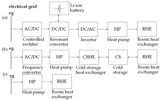
Figure 1.
Energy conversion in storage systems fed by the electrical grid (EG) with (a) a system with Li-ion batteries charged at low-price hours and supplying an HP and its RHE in daytime rush hours (process A); (b) a system with cold storage energy charged at low-price hours and supplying an RHE in daytime rush hours (process B); and (c) a conventional air-conditioning system with a heat pump working on demand regardless of the tariff (process C).
- Electrochemical lithium-ion storage with modern power electronic converters [29,30,31];
- Cold energy storage based on a prototype developed by the authors [32,33,34].
Both systems were designed and tested in the authors’ research laboratory. The lithium-ion storage system incorporates high-efficiency converters developed by the authors [29]. The cold energy storage prototype represents an original concept. Its mathematical model describes the melting process and suggests that periodic disturbances facilitate the formation of ice slurry, which influences the cooling factor. This, in turn, enhances the dynamics of cold accumulation and increases the rate of thermal exchange. The developed prototype was recognised at the Invention Exhibitions in Geneva [35] and Valencia [36] in 2017 and 2018, respectively.
Despite significant advancements in ion storage battery technology, as reflected in improved performance and reduced costs [37], the appeal of thermal storage tanks remains undiminished. This article investigates their ongoing relevance and comparative advantages.
A comparison is presented between the energy efficiency of an air-conditioning system incorporating the described cold storage (Figure 1b), a system using lithium-ion batteries (Figure 1a) and a baseline configuration supplied directly by the grid and operating without storage (Figure 1c).
This paper presents a formal mathematical description of the ice fragmentation process within the carrier mixer and its influence on the dynamics of thermal energy exchange. The primary aim of the study is to compare the overall energy efficiency of the examined systems and to analyse the associated energy costs. These objectives are addressed in the subsequent sections. The modelling procedure begins with a description of the architecture and key parameters of the evaluated control systems, followed by the development of a cooling tower model that incorporates freezing process analysis. It then proceeds to define the systems’ operating characteristics and details the computational procedures performed. The results include histograms illustrating electricity costs related to the most cost-effective solution.
The article does not address a comparative discussion of control capabilities, functional flexibility or other characteristics of the technologies under consideration. Such features can be meaningfully evaluated only within the context of specific projects, where individual components are clearly defined. Nevertheless, it can be stated with high confidence that systems incorporating electrochemical storage and power electronic converters exhibit superior flexibility and faster control dynamics. This flexibility arises from the ability to supply various types of loads beyond air-conditioning systems, while the enhanced dynamics results from the use of advanced vector control strategies in modern converter systems. These strategies are often based on mathematical models formulated in rotating reference frames, enabling the system to meet stringent requirements for power grid interaction quality. In contrast, the control of thermal storage systems does not demand such dynamic performance and is typically based on models defined in stationary reference frames.
2. Structure and Properties of the Innovative Cold Storage System
In the developed prototype storage design, the substance storing thermal energy is distilled water. To cool it, a significantly modified air-conditioning system is used, which is a prototype demonstrator design. Its block diagram is composed of a two-circuit system (Figure 2):
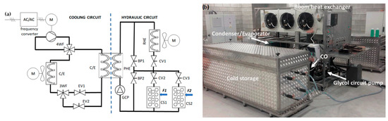
Figure 2.
(a) Test setup scheme with Li-ion batteries for supply of heat pump (HP) with room heat exchanger (RHE). EV1, EV2—expansion valves; C/E—condenser/evaporator; RHE—room heat exchanger; 4WV—four-way valve; 3WV—three-way valve; CO—compressor; F1, F2—the forces moving the storage, resulting in the fragmentation of ice surfaces. (b) Photo of the prototype system.
- The first is the hydraulic circuit, which is equipped with a glycol circulation pump (GCP), controlling valves (CVs) and by-pass (BP) valves, cold storage (CS) and a room heat exchanger (RHE).
- The second is the cooling circuit, equipped with a condenser–evaporator (C/E), compressor (CO) and a multi-way valve scheme with a 3WV, electronic expansion valves EV1 and EV2, which allow for a quick change in the refrigerant’s flow direction. This circuit can work in two modes: as a cooling system or as a heat pump. Both systems are linked through a plate heat exchanger (PHE) separating the refrigerants and allowing for heat exchange between circuits. This construction allows for uninterrupted heat exchange between final destinations.
An important role in the operation of the system is fulfilled by carefully selected electronic valves [38] and a control algorithm. A detailed description of the construction can be found in the indicated patent application [32]. For example, the refrigeration circuit used valves, which changed the direction of the refrigerant circuit. This allowed us to compose an operational circuit which performs tasks such as charging/discharging the cold storage or works directly on the room heat exchanger, omitting the cold storage.
In order to reduce the mass of the cold storage, it is beneficial to store thermal energy using a refrigerant, a substance which accumulates the majority of the energy [39]. In these physical conditions, this substance stores latent heat without changing the temperature [40]. This latent heat is the amount of energy that needs to be stored during phase change—in the designed system from water to ice [16,41].
Inside the cold storage unit, a set of small, barrel-shaped containers is arranged, each filled with either water or a water-based solution. These containers are made of mechanically robust materials, such as polymers, which also exhibit favourable thermal conductivity properties. They are immersed in a continuously circulating refrigerant—typically a glycol–water mixture—to facilitate effective heat exchange.
A series of tests were conducted to examine the properties of the proposed system. Representative results are presented in Figure 3a,b. Figure 3a illustrates the phase transition of distilled water from liquid to solid state. During this process, the cartridge stores energy in the form of latent heat, maintaining a constant temperature for approximately 170 min—allowing for substantial thermal energy accumulation. A similar pattern is observed during the discharge phase (Figure 3b), where the temperature initially increases linearly until the onset of the phase transition. Over the next 400 min, the cartridge sustains a stable temperature, after which a linear rise resumes.
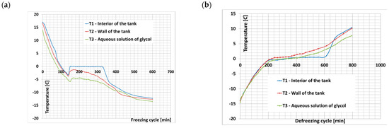
Figure 3.
Cartridge temperature during work cycle: (a) charging–freezing cycle and (b) discharging–defreezing cycle.
The novelty of this solution comes from the following:
- The use of multi-way hydraulic circuits which increase the heat exchange dynamic;
- Enforcing the container’s vibration, leading to ice layer crushing;
- Specific characteristics of the internal cooling medium circuit, which improve the container’s cooling process uniformity in its entire volume.
These characteristics also result from the specific arrangement of PCM (phase change material)-filled containers, which is designed to induce automatic mixing of the glycol solution through turbulent flow [42]. This configuration effectively eliminates undesirable thermal bridges that would otherwise impede the cold storage process. Additionally, the shape and spatial distribution of the PCMs enhance heat exchange performance, thereby improving the overall efficiency of the system.
3. Effect of Container Vibration on the Freezing Process
During freezing, a layer of ice forms on the inner surface of the container, which increases the thermal resistance and reduces the freezing rate. During the freezing process, the container is periodically shaken to break the frozen layer. The frozen layer is broken down and forms ice slurry [16].
To describe and analyse the model of water freezing in the cold storage, the following assumptions were made:
1. Ice slurry transports cold just like chilled water, but dendrites may grow on the surface of fragmented ice.
2. Only the properties of the refrigerant (water) inside the battery change periodically. The properties of the refrigerant in the system remain unchanged within the plate heat exchanger in question.
The classic cooling process using a PCM (phase change material) includes three stages that characterise the energy transport to cold HTF (heat transfer fluid). In the first stage (precooling stage), the temperature of the PCM stored in the containers drops to the freezing point. In the second stage, the phase change continues until the entire volume of the PCM in the containers is frozen. The third stage (further cooling stage) is the further transfer of heat from the fillings to the colder HTF [17]. At this stage, the solid-state PCM temperature drops to temperatures below its freezing point, and this stage continues until the cooling period is complete [43,44].
The system described uses a phase change material (PCM), which enables the design of modular configurations. This allows for the addition of material containers or the development of new containers with capacities tailored to specific requirements. As a result, the process is scalable.
The freezing time τf includes the following stages: initial cooling τc, proper freezing τfp and ice temperature lowering (tempering) τt [45].
The second stage, which changes the state of matter, is important for the heat storage process. The apparent heat of the frozen substance and the latent heat of freezing are removed. The freezing point changes during the cooling process and ice forming.
Figure 4 presents a cross-section of the cylinder which is cooled at the surface.
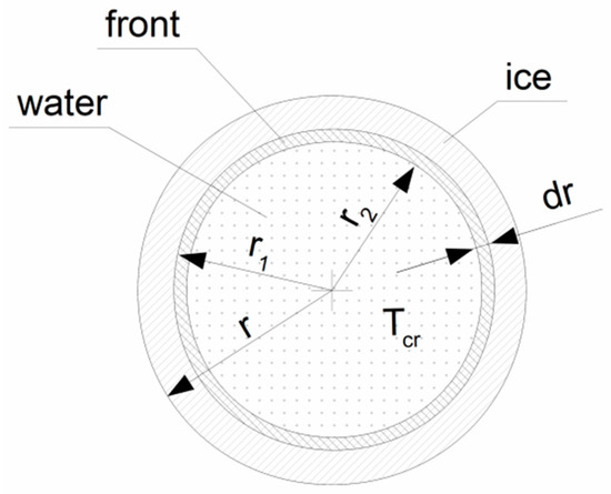
Figure 4.
A cross-section of the cylinder which is cooled at the surface. The freeze front is between r1 and r2.
The elementary freezing time of the freezing water in the cylinder cooled on the surface of the mantle is
where
- qf—specific heat of freezing [J/kg];
- ρf—specific density [kg/m3];
- Tcr—temperature of centre [K];
- α—heat transfer coefficient [W/(m2 K)];
- λf—thermal conductivity coefficient of the frozen product [W/(m K)];
- r—radius [m];
- rx—radius in the range (r–0).
Total time τf is the time it takes for the freezing front to travel from the surface of the container to its axis (centre). When we integrate over intervals τ(0, τf) and rf(r, 0), we obtain
For the cold storage process, it is important to reduce the freezing time of the entire volume of the container, i.e., to maintain the freezing speed obtained in the initial stage of the freezing phase. The proposed solution uses periodic crushing of the ice layer. The period of the ice build-up and crushing cycle should be longer than the time needed for the formation of the “initial” elemental ice layer after the glacial front (dendrite formation zone) has passed and shorter than that resulting from thermal resistance [18,19].
The freezing rate [K/h] of a cylinder cooled on a surface is expressed by the following formula:
The initially high value of the freezing rate decreases to a minimum (w → wmin). However, in the vicinity of the cylinder axis, it grows to infinity (wmin → ∞) [45].
In Figure 5, the temperature profile during the melting of thermal dendrites is presented. The profile smoothes as the thickness of the ice layer increases (thermal resistance increases).
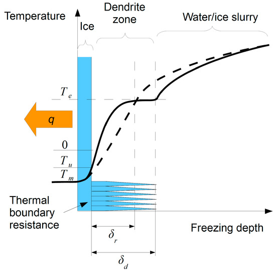
Figure 5.
Temperature profile Te during the melting of thermal dendrites. Solid line—initial phase of crystal formation; dashed line—moment of consolidation to the depth of δr; δd—liquid supercooling depth; Tm—temperature of refrigerant; Tu—crystal seed formation temperature; Te—equalisation temperature. (Based on [45]).
Based on Figure 4 and Figure 5, the freezing zones of the container’s contents can be distinguished:
1: rx in the range (r–r1)—ice (increase in thermal resistance);
2: rx in the range (r1–r2)—dendrite zone, freezing front (temperature rise zone);
3: rx in the range (r2–0)—liquid water.
For a cylinder cooled on the mantle’s surface, assuming a constant thickness of the freezing layer δr, the freezing rate decreases with depth and reaches a minimum in the range of 0.4–0.5 r from the cylinder axis (depending on the value of the alpha coefficient) and then increases due to a reduction in the liquid volume and the amount of heat dissipated. Therefore, the boundary conditions of the distinguished freezing zones are
1: ;
2: ;
3:
The aim of the authors was to extend the first phase of freezing ice on the wall to the depth rx. The extension of the first freezing phase is achieved by the multiplication of this phase in the freezing cycle of the entire volume of the container.
The freezing process, as proposed by the authors, includes the following stages:
- Frosting the ice layer for 10 min to thickness r-r1 (lowering the temperature by 0.411 °C/min).
- Shaking to break the ice layer and thicken the ice slurry.
- Repeating the cycle until the entire volume of the container is frozen.
- At some point in the process, the thickness of the ice that is formed exceeds the limit at which it cannot survive, and the ice crust is not crushed.
- Discontinuation of shaking the container.
The ice layer crystal fragmentation reduces the thermal resistance of the water inside [20]. After the water is supercooled, ice crystals are initiated on the surface of the crushed ice. The formation of an ice slurry additionally cools the liquid water. The total freezing time is then
where n is the number of freezing cycles and
Figure 6 presents the freezing rate during the process with freeze layer fragmentation cycles. The laboratory tests of the demonstrator show that the period of intense accumulation of cold lasts for about 10 min.
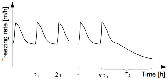
Figure 6.
Freezing rate during the process with freeze layer fragmentation cycles.
The transformation of the ice layer into an ice slurry must occur periodically. Continuous shaking would damage the ice forehead and make it difficult to freeze the water due to the temperature increase in the dendrite formation zone.
Freezing and melting models are known; an example is the simulation results presented in [46,47]. However, an appropriate model for describing the turbulent flow of ice suspensions is still missing. These difficulties are related to the time-dependent variation in rheological properties such as shear stress, apparent viscosity, critical shear stress and effective thermal conductivity [48].
The presented mathematical model explains the phase transitions in the storage system’s charging and discharging cycle in the context of the daily operating cycles of a storage system used to cool rooms in a public building. Model validation has been planned for the system’s effectiveness over the whole summer season. Preparations are underway to run the equipment in a continuous cycle for this period [47,48,49,50,51].
4. System Based on Lithium-Ion Batteries with Integrated Power Electronic Converters
An alternative to thermal accumulators is electrochemical batteries, e.g., of the lithium-ion type. Such a system is shown in Figure 7. Electrochemical batteries, along with power electronic converters, form a buffer between the grid or renewable energy source and the heat pump compressor drive. These batteries require precise charging and discharging control. The devices required for this process download operating parameters from the battery management system. Both current and voltage during charging and discharging depend on the battery’s state of charge. However, battery safety can be enhanced by using cells manufactured with high-safety technologies, such as lithium–iron–phosphate (LFP), lithium–titanate (LTO) and the recently developed sodium-ion (Na-ion) technology.
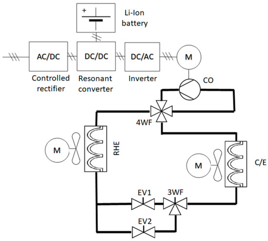
Figure 7.
Test setup diagram with Li-ion batteries for supply of heat pump (HP) with room heat exchanger (RHE). EV1, EV2—expansion valves; C/E—condenser/evaporator; RHE—room heat exchanger; 4WV—four-way valve; 3WF—three-way valve; CO—compressor.
Figure 7 shows the BMS-controlled resonant DC/DC converter [29,30,31], AC/DC dynamic rectifier and DC/AC inverter [37], which supplies the motor of the heat pump compressor with electricity. Thanks to the high converter dynamics, it is possible to force operational characteristics and reduce the temperature regulation time. Moreover, the fast electronic valves used here eliminate the dead time of the mechanical valves and improve the speed response of the heat pump (HP). The room heat exchanger (RHE) is a subsystem that allows for heat exchange with the surroundings.
5. Efficiency Comparison of the Systems Considered
The experiments carried out are based on a comparison of the energy efficiency of both described processes and a system where the cooling circuit is directly supplied by the electrical grid. During the calculations, it was assumed that charging and discharging take place in a 24 h cycle, presented in Figure 8. Storage charging takes place during nighttime, between 10 p.m. and 6 a.m. This time is dictated by a lower energy tariff and lesser power restrictions during the night. For a system with cold storage, one additional reason is a higher coefficient of performance (COP) of the heat pump due to a lower environmental temperature during the night hours.
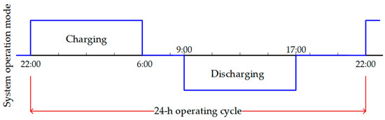
Figure 8.
The 24 h operating cycle of energy storage. The charging of cold or Li-ion storage systems takes place between 10 p.m. and 6 a.m., while discharging is between 9 a.m. and 5 p.m.
The times of charging and discharging are assumed to be the same (Figure 8), although, especially for the cold storage system, discharge occurs with less power than the charging process. The latter outcome is due to the fact that over-sizing of the cold storage, unlike Li-ion batteries, does not generate a significant increase in financial terms.
During the discharge period of the system with Li-ion batteries, the accumulated electrical energy supplies the heat pump, which produces cold. For a system with cold storage, during discharging, there are no more energy conversions, and thermal energy from cold storage is directly released through the room heat exchanger to the surrounding room [23].
The operating parameters for both processes are coherent with the description in Figure 1. For the Li-ion battery, the parameters are marked using the letter A and indexes from A0 to A7, while for the cold storage, they are marked with indexes B0 to B6. These indexes are assigned to the energy efficiency coefficient η and the coefficient of heat pump performance (COP). These parameters are described in Table 1 (process A) and Table 2 (process B). Calculations for both systems in terms of temperature are shown in Figure 9.

Table 1.
Parameter description for process A with Li-ion batteries and power electronic converters.
Table 2.
Parameter description for process B with the cold storage system.
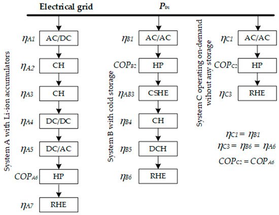
Figure 9.
Effectiveness calculations: subsystem efficiencies taken into consideration in calculations of total effectiveness.
The values of each of the above parameters were determined based on the results of the experiments described in [33,34], as well as on the basis of recognised bibliographic publications [24,25].
According to the three structures shown in Figure 1, suitable calculations were performed based on Formulas (6) and (7):
For a lithium-ion-based system:
For a cold-storage-based system:
where
Pin—input power;
t—supply time of input electric power Pin.
The subsystem parameters shown in Table 1 and Table 2 are based on previously performed research and the literature [16,34]. A value that allows us to objectively determine the total energy efficiency is the TEE factor, which is the ratio of useful energy to input (8):
where subscript x determines one of the analysed processes A, B or C.
For the considered structures, the total energy efficiency is further calculated according to Formulas (9)–(11):
For the assumed data, the calculated total energy effectiveness (TEE) coefficients are TEEA = 1.84, TEEB = 2.16 and TEEC = 2.21.
Potentially higher capabilities are achieved when using thermal energy storage. The operating effectiveness is based mostly on the ambient temperature during a period of cold storage charging. It comes from the heavy dependency of the COP in terms of the ambient temperature. However, if both storage systems were charged in similar heat conditions, their total effectiveness would be almost identical. This is depicted in Figure 9.
It needs to be noted that lithium-ion storage and power electronic converters are repetitive systems—two different storage systems will have the same parameters as long as they are built using the same technology with SiC-based semiconductors. This is different for cold storage. The tested system is a prototype and is under constant development. Therefore, further improvements are to be expected, especially in the case of the COP, and should additionally raise the efficiency of this solution.
Figure 10 shows the temperature’s impact on the COP. The lower the temperature, the faster the COP grows. During days with high air temperature, the heat exchange system at its fixture point reaches above 40 degrees Celsius. This results in the COP falling to a value of 1.8. Conditions at low COP values characterise work in the analysed systems A and C.
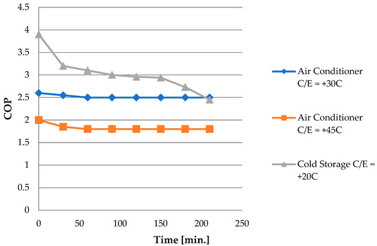
Figure 10.
Coefficient of performance (COP) of the compared systems: with cold storage (grey line) and Li-ion batteries as well as a conventional air-conditioning system (blue and orange lines).
In consequence, this emphasises the advantages of supplying an ac system at night, when the temperature is much lower than during the daytime.
6. Estimation of Operating Costs
The analysis is based on standardised parameters that enable a direct comparison of the economic efficiency of both systems. Table 3 presents the main assumptions adopted for the analysis.
Table 3.
Input assumptions for the analysis.
A comparative analysis was conducted to evaluate two alternative cold storage solutions with a usable capacity of 100 kWh: (1) a system based on a cold storage tank (CS—cold storage) and (2) a system comprising an electrical energy storage unit (ES—energy storage) and a heat pump (HP—heat pump) operating in cooling mode. The assessment accounted for actual differences in energy efficiency, seasonal demand distribution and performance variability due to operational temperature conditions. The estimation of electrical energy demand is based on the known values of the coefficient of performance (COP) and the percentage of energy losses during conversion. In the ES system, the cooling unit is powered by an energy storage system, which undergoes gradual degradation over its operational lifetime (1500 cycles). The assumed capacity loss over the entire period of use is approximately 7.5%. In order to ensure a dispatchable supply of 51.8 kWh of electrical energy at the most degraded point in the system’s life cycle, the initial capacity of the energy storage must be sized at 60 kWh. The annual electricity consumption of the ES + HP system was estimated at 5653 kWh, yielding an overall efficiency of 1.93. In contrast, the CS system consumed 4845 kWh/year, achieving an efficiency of 2.27. This performance advantage is primarily due to the higher coefficient of performance (COP) under nighttime conditions (CS: COP = 3.09 at +20 °C vs. ES + HP: COP = 2.5 at +30 °C). For the cost analysis, the annual demand for cold was assumed as follows: 100 kWh for 90 days, 50 kWh for 30 days and 25 kWh for 20 days [27]. Table 4 and Table 5 present a cost breakdown of capital expenditures (CAPEXs), operating expenditures (OPEXs) and total life cycle costs (LCCs) over a 15-year operational period. The projection assumes an annual energy price increase of EUR 0.01 and a fixed exchange rate of EUR 1 = PLN 4.16.
Table 4.
Estimated investment costs for ES + HP system.
Table 5.
Estimated investment costs for cold storage (CS) system.
According to the findings, the CS system demonstrates a lower total life cycle cost (LCC)—approximately 16% less than the ES + HP system—Table 6. Notably, the capital expenditure (CAPEX) of the CS solution is 19.44% lower, and the system achieves higher overall efficiency, despite relatively greater energy conversion losses [28].
Table 6.
Annual operating costs for 15 years.
Although the operational costs are higher, the ES + HP system offers superior functional flexibility, capable of both heating and cooling, which enhances its value in year-round applications and hybrid energy systems (e.g., with photovoltaics or waste heat recovery). On the other hand, the cold storage tank, despite being simpler to implement and degradation-resistant (no capacity loss over time), lacks such flexibility, limiting its use to daily cold storage cycles. A critical challenge in modern energy systems is aligning consumption profiles with the generation characteristics of intermittent renewable energy sources (RESs). The so-called “duck curve” illustrates steep drops in net demand midday (due to PV peak generation) and corresponding evening peaks. The ES + HP system, supported by an energy storage unit, can charge during low-demand/high-generation periods (e.g., midday) and discharge cold during peak hours, thereby aiding grid balancing and increasing its systemic value as RES penetration rises. In contrast, the CS system has limited temporal flexibility, requiring prior charging and reducing its ability to respond to market or production volatility. The implementation of dynamic tariffs creates opportunities to optimise operating costs by shifting energy usage to periods of lower prices. The ES + HP system, equipped with advanced EMS control, can dynamically manage both charging and HP operation, enabling significant savings. The CS system, though simpler to control, is less adaptable to price fluctuations, potentially reducing its cost-effectiveness in volatile markets requiring rapid energy profile adjustments.
A summary of the total life cycle costs over a 15-year time horizon is presented in Table 7. Operational costs were averaged and multiplied by the number of operational years, assuming stable electricity prices and excluding discounts.
Table 7.
Life cycle cost (LCC).
The conducted analysis indicates that the cold-storage-based system is significantly more cost-effective over its life cycle—up to 40% cheaper compared to the ES + HP system. This difference primarily results from the high investment costs associated with ES + HP, particularly the battery system and compressor-based cooling components. On the other hand, the ES + HP system benefits from lower operating costs and offers greater operational flexibility. It can provide both heating and cooling functions, enhancing its value in the context of renewable energy integration and year-round applications. In scenarios where subsidies or incentives for low-emission technologies are available, investment in the more expensive ES + HP system may be justified.
The cold storage (CS) system offers lower life cycle costs, higher energy efficiency and minimal technological degradation, making it a cost-effective and operationally simple solution. Furthermore, its structurally simple design and the use of low-cost, readily available materials contribute to the long-term reliability of the CS technology, reinforcing its suitability for sustainable infrastructure applications. In contrast, the ES + HP system, although more expensive, delivers greater functionality and flexibility, making it better suited for dynamic tariffs, PV integration and year-round operation. The final technology choice should be based on the specific application context, available energy sources, functional requirements and integration possibilities with energy management systems and renewable infrastructure, as well as environmental criteria such as the absence of a negative impact on the surroundings, the use of non-polluting technologies, a long operational lifespan and the overall cost-effectiveness.
7. Conclusions
The developed cold container system shows competitive characteristics in comparison to similar solutions. The novel solution using container vibration leads to ice layer fragmentation of the dendrites and creation of ice slurry, which in turn increase heat exchange dynamics. This process was described by a mathematical model, which helped to define intervals of the vibrations. The container’s blueprint and its internal arrangement limit the possibility of thermal bridge creation by the intensification of the mixing processes around areas where the coolant’s flow may be limited.
The system’s competitive characteristics were proven in comparative studies against other common solutions. The first of the compared systems was a typical heat pump whose power supply was retrofitted with Li-ion batteries and an arrangement of AC/DC, DC/DC and DC/AC power electronic converters. The other compared system was a conventional air-conditioning solution working under the on-demand regime and directly fed by the grid.
The results achieved clearly point out that using cold storage is more profitable than using Li-ion storage. The global economic effectiveness with cold storage operating at night, when the heat pump reaches higher COP values, can be up to 17% higher than in a Li-ion-based system and 88% higher than in a conventional air-conditioning system. By applying a cold storage system, it is possible to drastically reduce the cost of electrical energy. The proposed system minimises the air-conditioning impact on the electric current network and increases grid efficiency and flexibility. Discovering this property is a very important achievement, and it has great application potential.
This paper does not exhaust the problem. Different tariffs during daytime and nighttime were left untouched, as were the investment costs for both storage systems and their operation and utilisation costs. Taking these terms into consideration should further increase the attractiveness of the cold storage technology described. This is revealed by the calculations and further elaborated in the analysis [24,25].
An advantage of the system is that vibrations in the process accelerate ice nucleation and lead to the formation of finer ice crystals, which enhances heat transfer and allows better control of the freezing process. The innovative aspect lies in the phase preceding the final implementation of the system in practice.
The present comparative analysis does not cover all relevant issues. Among the omitted aspects are the controllability and operational flexibility of both technologies. If these factors were prioritised by the investor, the technology based on electrochemical batteries would likely receive a higher evaluation. This is because systems using lithium-ion batteries demonstrate greater operational flexibility, as the dynamics of the charging and discharging processes in the configuration involving a power electronic converter and an electrochemical battery are significantly higher. Therefore, the choice of a solution depends on the established priorities. While the authors of this article primarily assessed both technologies from the perspective of energy performance, efficiency and cost, it is crucial to recognise that a conscious and forward-looking society must also incorporate sustainability considerations. The technology selected for implementation should fully embody the core principles of sustainability: it should avoid the depletion of natural resources, minimise the environmental impact, ensure long-term reliability and promote lower energy costs alongside responsible resource management. The issue of sustainability has been repeatedly emphasised throughout this study, and the authors foresee its further development through comparative research focused on the environmental friendliness of the air-conditioning technologies under consideration.
Author Contributions
Conceptual and structural design and supervisory oversight, W.J.; idea of the cold storage, D.Z.; project construction of laboratory setup, D.Z. and M.F.; validation and tests of laboratory systems, M.F. and D.Z.; mathematical modelling, P.W. and G.L. All authors have read and agreed to the published version of the manuscript.
Funding
This research received no external funding.
Institutional Review Board Statement
Not applicable.
Informed Consent Statement
Not applicable.
Data Availability Statement
Not applicable.
Conflicts of Interest
The authors declare no conflicts of interest.
Abbreviations
| 3WV, 4WV | Three-, four-way valve |
| AC/DC | Power electronic converter of alternating current to direct current |
| ac | Air conditioning system |
| BP1, BP2 | Regulating valves |
| C/E | Condenser/evaporator |
| CO | Compressor |
| COP | Coefficient of performance |
| CS | Cold storage |
| CSHE | Cold storage heat exchanger |
| CV1, CV2, CV3 | Regulating valves |
| DC/DC | Power electronic converter of direct current to direct current |
| DC/AC | Power electronic converter of direct current to alternating current |
| DSR | Demand-side response |
| EV1, EV2 | Expansion valves No. 1 and 2 |
| GCP | Glycol circulation pump |
| HP | Heat pump |
| PCM | Phase change material |
| PHE | Plate heat exchanger |
| RHE | Room heat exchanger |
References
- Angrisani, G.; Roselli, C.; Sasso, M. Distributed microtrigeneration systems. Prog. Energy Combust. Sci. 2012, 38, 502–521. [Google Scholar] [CrossRef]
- Andersson, G.; Donalek, P.; Farmer, R.; Hatziargyriou, N.; Kamwa, I.; Kundur, P.; Martins, N.; Paserba, J.; Pourbeik, P.; Sanchez-Gasca, J.; et al. Causes of the 2003 major grid blackouts in north America and Europe, and recommended means to improve System Dynamic Performance. IEEE Trans. Power Syst. 2005, 20, 1922–1928. [Google Scholar] [CrossRef]
- Parra, D.; Norman, S.A.; Walker, G.S.; Gillott, M. Optimum community energy storage system for demand load shifting. Appl. Energy 2016, 174, 130–143. [Google Scholar] [CrossRef]
- Werminski, S.; Jarnut, M.; Benysek, G.; Bojarski, J. Demand side management using DADR automation in the peak load reduction. Renew. Sustain. Energy Rev. 2017, 67, 998–1007. [Google Scholar] [CrossRef]
- Yan, C.; Xue, X.; Wang, S.; Cui, B. A novel air-conditioning system for proactive power demand response to smart grid. Energy Convers. Manag. 2015, 102, 239–246. [Google Scholar] [CrossRef]
- Rabkowski, J.; Piasecki, S.; Kaźmierkowski, M.P. Design of a three-phase AC/DC converter with paralleled SiC MOSFETs. In Proceedings of the 16th International Power Electronics and Motion Control Conference and Exposition, Antalya, Turkey, 21–24 September 2014. [Google Scholar]
- Angrisani, G.; Canelli, M.; Roselli, C.; Sasso, M. Integration between electric vehicle charging and mi-cro-cogeneration system. Energy Convers. Manag. 2015, 98, 115–126. [Google Scholar] [CrossRef]
- Rothgang, S.; Baumhöfer, T.; van Hoek, H.; Lange, T.; De Doncker, R.W.; Sauer, D.U. Modular battery design for reliable, flexible and multi-technology energy storage systems. Appl. Energy 2015, 137, 931–937. [Google Scholar] [CrossRef]
- Roskilly, A.P.; Taylor, P.C.; Yan, J. Energy storage systems for a low carbon future—In need of an integrated approach. Appl. Energy 2015, 137, 463–466. [Google Scholar] [CrossRef]
- Smallbone, A.; Jülch, V.; Wardle, R.; Roskilly, A.P. Levelised Cost of Storage for Pumped Heat Energy Storage in comparison with other energy storage technologies. Energy Convers. Manag. 2017, 152, 221–228. [Google Scholar] [CrossRef]
- Sharma, A.; Tyagi, V.V.; Chen, C.R.; Buddhi, D. Review on thermal energy storage with phase change materials and applications. Renew. Sustain. Energy Rev. 2009, 13, 318–345. [Google Scholar] [CrossRef]
- Cui, B.; Wang, S.; Yan, C.; Xue, X. Evaluation of a fast power demand response strategy using active and passive building cold storages for smart grid applications. Energy Convers. Manag. 2015, 102, 227–238. [Google Scholar] [CrossRef]
- Xue, X.; Wang, S.; Yan, C.; Cui, B. A fast chiller power demand response control strategy for buildings connected to smart grid. Applied Energy 2015, 137, 77–87. [Google Scholar] [CrossRef]
- Sciacovelli, A.; Gagliardi, F.; Verda, V. Maximization of performance of a PCM latent heat storage system with innovative fins. Appl. Energy 2015, 137, 707–715. [Google Scholar] [CrossRef]
- Kumano, H.; Hirata, T.; Shouji, R.; Shirakawa, M. Experimental study on heat transfer characteristics of ice slurry. Int. J. Refrig. 2010, 33, 1540–1549. [Google Scholar] [CrossRef]
- Kauffeld, M.; Wang, M.J.; Goldstein, V.; Kasza, K.E. Ice slurry applications. Int. J. Refrig. 2010, 33, 1491–1505. [Google Scholar] [CrossRef]
- Rahimi, A.; Farrokhi, A.M.; Hatamipour, M.S.; Moradi, M. Mathematical modeling and experimental study of a two-stage fixed-bed heat storage system for heat recovery of flue gases. Int. J. Heat Mass Transf. 2020, 159, 120125. [Google Scholar] [CrossRef]
- Petzold, G.; Aguilera, J.M. Ice Morphology: Fundamentals and Technological Applications in Foods. Food Biophys. 2009, 4, 378–396. [Google Scholar] [CrossRef]
- Zhao, L.; Pan, L.; Ji, A.; Cao, Z.; Wan, Q. Recrystallization of freezable bound water in aqueous solutions of me-dium concentration. Chin. Phys. B 2016, 25, 075101. [Google Scholar] [CrossRef]
- Pacheco, H.J.; Braga, S.L. Transport Coefficients of Ice Slurry in Plate Heat Exchanger. International Re-frigeration and Air Conditioning Conference. 2004.
- Aydin, D.; Casey, S.P.; Riffat, S. The latest advancements on thermochemical heat storage systems. Renew. Sustain. Energy Rev. 2015, 41, 356–367. [Google Scholar] [CrossRef]
- Selvnes, H.; Allouche, Y.; Manescu, R.I.; Hafner, A. Review on cold thermal energy storage applied to refrigeration systems using phase change materials. Therm. Sci. Eng. Prog. 2021, 22, 100807. [Google Scholar] [CrossRef]
- Blarke Morten, B. Towards an intermittency-friendly energy system: Comparing electric boilers and heat pumps in distributed cogeneration. Appl. Energy 2012, 91, 349–365. [Google Scholar] [CrossRef]
- Al-Abidi, A.A.; Mat, S.B.; Sopian, K.; Sulaiman, M.Y.; Lim, C.H.; Th, A. Review of thermal energy storage for air conditioning systems. Renew. Sustain. Energy Rev. 2012, 16, 5802–5819. [Google Scholar] [CrossRef]
- Steven Brown, J.; Domanski Piotr, A. Review of alternative cooling technologies. Appl. Therm. Eng. 2014, 64, 252–262. [Google Scholar] [CrossRef]
- Niu, J.; Zhang, C.; Li, Y.; Wu, Y.; Sun, H. Design and Investigation of Cold Storage Material for Large-Scale Ap-plication in Supercritical Compressed Air Energy Storage System. J. Energy Storage 2024, 75, 109680. [Google Scholar] [CrossRef]
- Ha, J.-W.; Cho, S.; Kim, H.-Y.; Song, Y.-H. Annual Energy Consumption Cut-Off with Cooling System Design Parameter Changes in Large Office Buildings. Energies 2020, 13, 2034. [Google Scholar] [CrossRef]
- Wang, N.; Zhang, J.; Xia, X. Energy consumption of air conditioners at different temperature set points. Energy Build. 2013, 65, 412–418. [Google Scholar] [CrossRef]
- Fatyga, K.; Kwaśny, L.; Stefańczak, B. A comparison study of the features of dc/dc systems with Si IGBT and SIC mosfet transistors. IAPGOS 2018, 8, 68–71. [Google Scholar] [CrossRef]
- Szcześniak, P.; Kaniewski, J. Power electronics converters without DC energy storage in the future electrical power network. Electr. Power Syst. Res. 2015, 129, 194–207. [Google Scholar] [CrossRef]
- Zieliński, D.; Fatyga, K. Comparison of main control strategies for DC/DC stage of bidirectional vehicle charger. In Proceedings of the 2017 International Symposium on Electrical Machines (SME), Naleczow, Poland, 18–21 June 2017. [Google Scholar]
- Zieliński, D.; Jarzyna, W.; Kolano, K. (2016). Method and System of Storing Heat or Cold in Vehicles with Electric Propulsion. Patent Assignee No (11) 227463 (21) 416882], News of the Polish Patent Office, 2017, Vol. 12, Pp. 4274.
- Jarzyna, W.; Zieliński, D.; Aftyka, A.; Fatyga, K. Cold storage-supported air conditioning system in urban transport vehicles. J. Ecol. Eng. 2016, 17, 120–127. [Google Scholar] [CrossRef]
- Zieliński, D.; Przytuła, K.; Fatyga, K. Operational characteristics of the heat and cold storage in traction vehicles. In Environmental Engineering V Congress; CRC Press-Taylor & Francis Group: Boca Raton, FL, USA, 2017; pp. 267–271. [Google Scholar]
- Gold and Silver Medals at the 45th INTERNATIONAL EXHIBITION OF INVENTIONS, Geneva, 11–15 April 2017.
- Gold Medal at the INNOVA—INTERNATIONAL EXHIBITION OF INNOVATIONS, Va-Lencia, 7–8 May 2018.
- Zieliński, D.; Fatyga, K. Attenuation of DC-link pulsation of a four-wire inverter during phase unbalanced current operation. Appl. Sci. 2021, 11, 1322. [Google Scholar] [CrossRef]
- Wang, Z.; Xu, Z.; Gao, F.; Rui, S. Experimental Study on Flow Characteristics of the Electronic Expansion Valve with Variable Condition. In Proceedings of the 2010 Asia-Pacific Power and Energy Engineering Conference, Chengdu, China, 28–31 March 2010; pp. 1–4. [Google Scholar]
- Lin, X.; Lee, H.; Hwang, Y.; Radermacher, R. A review of recent development in variable refrigerant flow systems. Sci. Technol. Built Environ. 2015, 21, 917–933. [Google Scholar] [CrossRef]
- Oro, E.; Gracia, A.; Castell, A.; Farid, M.M.; Cabeza, L.F. Review on phase change materials (PCMs) for cold thermal Energy storage applications. Appl. Energy 2012, 99, 513–533. [Google Scholar] [CrossRef]
- Navarro, L.; De Gracia, A.; Colclough, S.; Browne, M.; McCormack, S.J.; Griffiths, P.; Cabeza, L.F. Thermal energy storage in building integrated thermal systems: A review. Part 1. Active storage systems. Renew. Energy 2016, 88, 526–547. [Google Scholar] [CrossRef]
- Khana, Z.; Khana, Z.; Ghafoor, A. A review of performance enhancement of PCM based latent heat storage system within the context of materials, thermal stability and compatibility. Energy Convers. Manag. 2016, 115, 132–158. [Google Scholar] [CrossRef]
- Rafałko, G.; Mosdorf, R.; Litak, G.; Górski, G. Complexity of phase distribution in two-phase flow using composite multiscale entropy. Eur. Phys. J. Plus 2020, 135, 661. [Google Scholar] [CrossRef]
- Tiwari, V.K.; Kumar, A.; Kumar, A. Enhancing ice slurry generation by using inclined cavity for subzero cold thermal energy storage: Simulation, experiment and performance analysis. Energy 2019, 183, 398–414. [Google Scholar] [CrossRef]
- Gruda, Z.; Postolski, J. Freezing Food; WNT: Warsaw, Poland, 1999. (In Polish) [Google Scholar]
- McDonald, A.; Bschaden, B.; Sullivan, E.; Marsden, R. Mathematical simulation of the freezing time of water in small diameter pipes. Appl. Therm. Eng. 2014, 73, 140–151. [Google Scholar] [CrossRef]
- Egolfa, P.W.; Kitanovskia, A.; Ata-Caesara, D.; Stamatioub, E.; Kawajib, M.; Bedecarratsc, J.-P.; Strub, F. Ther-modynamics and heat transfer of ice slurries. Int. J. Refrig. 2005, 28, 51–59. [Google Scholar]
- Dzierwa, P.; Taler, J.; Peret, P.; Taler, D.; Trojan, M. Transient CFD simulation of charging hot water tank. Energy 2022, 239 Pt C, 122241. [Google Scholar] [CrossRef]
- Yau, Y.H.; Lee, S.K. Feasibility study of an ice slurry-cooling coil for HVAC and R systems in a tropical building. Appl. Energy 2010, 87, 2699–2711. [Google Scholar] [CrossRef]
- Allouche, Y.; Szabolcs Varga, S.; Bouden, C.; Oliveira, A.C. Validation of a CFD model for the simulation of heat transfer in a tubes-in-tank PCM storage unit. Renew. Energy 2016, 89, 371–379. [Google Scholar] [CrossRef]
- Pawar, V.R.; Sobhansarbandi, S. CFD modeling of a thermal energy storage based heat pipe evacuated tube solar collector. J. Energy Storage 2020, 30, 101528. [Google Scholar] [CrossRef]
Disclaimer/Publisher’s Note: The statements, opinions and data contained in all publications are solely those of the individual author(s) and contributor(s) and not of MDPI and/or the editor(s). MDPI and/or the editor(s) disclaim responsibility for any injury to people or property resulting from any ideas, methods, instructions or products referred to in the content. |
© 2025 by the authors. Licensee MDPI, Basel, Switzerland. This article is an open access article distributed under the terms and conditions of the Creative Commons Attribution (CC BY) license (https://creativecommons.org/licenses/by/4.0/).