Article

From Waste to Value: Recycling Industrial Waste into Functional ZnO Nanofibers

1
Institute of Materials Research, Slovak Academy of Sciences, Watsonova 47, 040 01 Kosice, Slovakia
2
Faculty of Materials, Metallurgy and Recycling, Technical University of Kosice, Letna 9, 040 01 Kosice, Slovakia
3
Institute of Physics, Faculty of Science, Pavol Jozef Safarik University, Park Angelinum 9, 041 54 Kosice, Slovakia
*
Author to whom correspondence should be addressed.
Sustainability 2025, 17(18), 8373; https://doi.org/10.3390/su17188373
Submission received: 26 August 2025 / Revised: 11 September 2025 / Accepted: 16 September 2025 / Published: 18 September 2025
(This article belongs to the Special Issue Sustainable Materials: Recycled Materials Toward Smart Future)

Abstract

This study details the sustainable synthesis and characterization of electrospun zinc oxide nanofibers, uniquely derived from industrial waste streams. Our approach leverages diverse industrial byproducts—specifically sal ammoniac skimming from hot-dip galvanizing, electric arc furnace dust, and galvanization flue dust—as sustainable raw materials. Following hydrometallurgical treatment with various leaching agents (HCl, (NH4)2CO3, or H2SO4) to obtain zinc-rich leachates, electrospinning solutions were formulated. The resulting fibers were subsequently calcined, yielding three distinct ZnO-based materials. Comprehensive characterization by XRD, SEM-EDX, and TEM revealed that the choice of leaching strategy significantly influenced the resultant fibers’ morphology and chemical composition. To demonstrate the potential applicability of these waste-derived materials, their photocatalytic activity was assessed through the degradation of methylene blue dye under UVA irradiation. ZnO fibers derived from HCl leaching exhibited remarkable photodegradation capabilities, achieving nearly complete dye removal within 690 min at optimal catalyst-to-dye ratios. Conversely, the H2SO4-prepared sample displayed impaired efficiency, primarily due to the formation of an undesirable Al2ZnO4 phase stemming from high aluminum content in the input waste, a critical consideration for waste-to-product strategies. The results showed that the cost-effective ZnO fibers obtained by electrospinning from industrial waste products have potential for applications in photocatalytic water treatment.

1. Introduction

With the annual increase in steel production comes a corresponding rise in the generation of solid, metal-bearing waste such as slags, dust, and other byproducts. This industry also includes the secondary production of steel in electric arc furnaces and the related production of electric arc furnace dust (EAFD). This is a fine-grained, heterogeneous material originating from gas removal during steel production. EAFD, in addition to other metals such as Fe, Pb, Mn, Ca, Mg, and Cu, contains about 30% zinc, mainly in the form of zincite (ZnO) and franklinite (ZnFe2O4) [1].
Approximately 10 to 25 kg of dust is produced per 1 ton of steel. The recycling of EAFD is currently an important and widely discussed topic, due to its high production volumes—world production exceeds 5–10 million tons [2]. Its hazardous nature and economic value are due to its polymetallic nature, and especially its zinc content. EAFD with a higher Zn content (25–45% [3]) is processed pyrometallurgically using the Waelz furnace process (WKP). EAFD hydrometallurgical processing is rarely used in industry. However, on a research scale, there are numerous studies describing acid leaching of EAFD using acids like H2SO4 [4,5], HCl [3,6,7], HNO3 [3,8,9], and other leachants [10,11,12]; however, there is also a possibility of using NH4Cl [13]. The resulting product is highly pure powdered ZnO [4,5,11].
The increased steel demand and production also affect the need for surface treatment, mostly as protection against corrosion. For this purpose, continuous or batch hot-dip galvanizing is most often used. Galvanizing is accompanied by the production of waste such as hard zinc, zinc ash, and galvanizing flue dust, which are characterized by a high Zn content and can therefore be considered valuable secondary raw materials. White fumes form above the zinc bath after dipping treated steel into molten zinc, which, after cooling, are captured as galvanizing flue dust (GFD) on filters. GFD is classified as hazardous waste due to its high content of zinc (~27.5%), chlorine (~31.44%), ammonia, Fe, and other elements such as Pb, Cu, Al, Sn, Mg, Ca, and Si [14,15,16,17]. The main phases in GFD are (NH4)2ZnCl4, (NH4)2ZnCl2, Zn5(OH)8Cl2·H2O, and (NH3OH)Cl. The cause of fume production is the decomposition of zinc chloride (ZnCl2) and ammonium chloride (NH4Cl) present in the flux (Reactions 1, 2) [15,16].
NH4Cl = NH3(g) + HCl(g)
Zn + 2HCl(ia) = ZnCl2(g) + H2(g)
GFD production is approximately 1 kg per ton of galvanized steel. The treatment of GFD is currently the subject of only a small number of scientific studies. The hydrometallurgical processing method is used to obtain various zinc and flux products [18,19]. The leaching of zinc is mainly carried out in hydrochloric acid. The choice of hydrochloric acid is due to the high content of chloride compounds in the GFD waste [15,18].
A specific waste that only occurs in wet processes is sal ammoniac skimming (SAS), which is formed by the interaction between molten zinc and the flux (NH4Cl) in the bath. While SAS consists of ammonium chloride, oxides, sulfides, and some other minor components, the main constituents are Zn(OH)Cl (96.43%) and NH4Cl (3.57%) [20]. This type of waste is currently not processed and is disposed of in landfills. The specialized literature provides very few publications on this topic. The available sources are focused on hydrometallurgical processing to obtain flux components reused in zinc plating [21] or the production of poorly soluble zinc compounds, e.g., ZnCO3 by precipitation [22]. In order to obtain metallic zinc, electrolysis from aqueous solutions as well as from molten salts has been applied [23]. Combined processing methods have also been applied, obtaining zinc in metallic form, ZnO, and a complex salt (ZnCl2.NH4Cl), which can be reused as a flux in the dry galvanizing process [20].
Zinc is economically important for the sustainable development of EU countries because of its widespread use in a variety of industries. It is among the deficient metals, and recycling zinc from secondary raw materials is one of the potential ways to obtain the metal. The zinc end-of-life recycling input rate (EOL-RIR) is currently 31% [24].
Zinc oxide (ZnO) is one of the most studied and promising semiconductors for photocatalysis thanks to the suitable band gap for utilizing UV light, as well as good photocatalytic activity, chemical stability, and low toxicity and abundance [25,26,27]. The chemical nature of ZnO allows it to be not only biologically degraded but also reused by living organisms.
According to the WHO, billions of people worldwide lack access to clean drinking water, leading to waterborne diseases and other health problems. The increasing water scarcity and pollution crisis underscore the urgent need for sustainable water management practices and global cooperation to protect this vital resource. Recent water pollution stems from various sources, including industrial activities, agriculture, and improper waste disposal. Microplastics, pharmaceuticals, heavy metals, and nutrient runoff pose significant threats to aquatic ecosystems and human health. Emerging contaminants further complicate the issue, highlighting the need for comprehensive solutions. One of the major issues in chemical water pollution is the presence of residual dyes from various sources (like the textile and paper industries), pharmaceuticals like antibiotics and hormones, or personal care product components [28], along with a wide range of persistent organic pollutants (POPs) from households and industry. These contaminants are frequently introduced into our natural water bodies and wastewater treatment systems. The removal of these organic contaminants before discharge into the environment is essential [26].
Advanced heterogeneous photocatalysis involving materials such as zinc oxide (ZnO) appears to be one of the promising technologies suitable for the removal of the abovementioned contaminants [25,27,29]. However, achieving high efficiency of heterogeneous photocatalysts is a complex problem that requires a complex solution. Recent trending approaches are based on choosing a suitable material design or architecture that provides a high surface area, good light absorption, and minimizes the loss of the material through morphology design and electron losses during light-induced excitation and electrochemical reactions [25]. Despite several disadvantages [30], nanoparticulate forms of catalysts have proven to be generally the most efficient. However, in recent years, metal doping or binary oxide photocatalysts have led to even further improvements in heterogeneous photocatalysis [25,30]. It has also been confirmed that doped ZnO may have higher photocatalytic activity compared to pristine ZnO. The literature describes ZnO doped and modified with elements such as Al, Sb, Mn, Ni, Co, Cu, Se, Cd, Fe, Hf, Pd, Ag, Bi, Li, Sb, Sn, Sr, alkali-metals (Na, K, Mg), and rare-earth metals (Ce, Dy, Er, Eu, Ho, Nd, Sm). Doping with C, N, and S has also greatly enhanced photocatalytic performance [25,27,31,32]. Besides metal doping, coupled semiconductors have been proven to enhance the charge separation of electron–hole pairs, which increases the lifetime of charge carriers and consequently reduces the recombination rates of electron–hole pairs [33]. The increase in photodegradation efficiency using the ZnO coupling system has been demonstrated by the preparation of materials such as CdO/ZnO, CeO2/ZnO, GO/ZnO, rGO/ZnO, NaNbO3/ZnO, RGO/ZnO, SnO2/ZnO, and TiO2/ZnO [27,32].
The photodegradation efficiency can be improved even more through advancements in the structure and morphology of the catalyst. ZnO nanoparticles show higher photocatalytic efficiency than bulk ZnO owing to their high surface area and high crystallinity. However, the use of nanoparticles suspended in solution as a photocatalyst is limited by the difficulty of separating nanoparticles from the solution and their strong tendency to aggregate into larger particles, decreasing their photocatalytic activity [30,34]. ZnO can be formed into films composed of nanoparticles to avoid these problems [30,34], but the 2D thin-film structure results in significant losses in surface area and thus photocatalyst activity. Granules or pellets of nanoparticles can be easily recovered from the solution [30,34]; however, the low surface-to-volume ratio of pellets limits light penetration to the inner part of the photocatalyst, leaving it inactive. Nanofibers consisting of nanosized ZnO grains offer the same advantages as nanoparticles, such as high surface area and surface-to-volume ratio, while the length of the fibers facilitates easy mechanical separation, even providing the opportunity for preparing membranes made solely of active ZnO ceramics [30,34].
A combination of the abovementioned techniques may dramatically enhance ZnO performance by shifting band gap energy, suppressing recombination rates of electron–hole pairs, increasing charge separation efficiency, improving hydroxyl radical production rates, producing smaller particle sizes with high specific surface areas, and allowing better dispersion in the medium, providing easy mechanical separation or even eliminating the need for it altogether [30,34].
Imran et al. fabricated ZnO nanofibers with diameters in the range of 124–197 nm by the electrospinning method using zinc acetate and PVA as materials for potential applications in renewable energy devices [35]. A similar approach was used in other studies [36,37], where authors prepared ZnO fibers. Fine ZnO nanowires with a mean diameter of 25.53 nm were produced by K. Thangavel et al. The optical properties of the latter were studied using spectrophotometry and confirmed to be suitable for application in optoelectronic nanodevices. The optical band gap energy was found to be 3.37 eV [38]. Centimeter-long aluminum-doped zinc oxide nanofibers with controlled morphology were prepared by electrospinning from an aqueous solution of polyvinyl alcohol (PVA), with the concentration of Al3+ increased from 0 to 3.0 at.%. This material was expected to have potential applications in gas sensing and optoelectronics.
This study demonstrates the versatility of needleless electrospinning for the cost-effective production of ZnO fibers from recycled materials. The primary objective was to optimize the electrospinning process for precursors of photocatalytically active ZnO fibers. This involved hydrometallurgical treatment of industrial waste, followed by needleless electrospinning and calcination of the resulting precursor fibers. The morphology and structure of the fibers were thoroughly characterized using scanning electron microscopy (SEM) and X-ray diffraction (XRD) analysis, with variations in leaching media considered. The photocatalytic activity of ZnO fibers derived from different recycled waste streams was evaluated for potential wastewater treatment applications.

2. Materials and Methods

2.1. Preparation of Zn-Enriched Leachates

The source of zinc used for the preparation of cost-effective ZnO fibers was input recycling solutions (Zn-enriched leachates) from the hydrometallurgical process of industrial waste treatment arising from various methods of zinc production: sal ammoniac skimming sample from wet-batch hot-dip galvanizing, electric arc furnace dust, and galvanizing flue dust. The main objective of the hydrometallurgical treatment of input samples of industrial waste was the maximum transfer of zinc into the solution. This also determined the conditions of the leaching experiments: the type of leaching medium (alkaline or acidic), its concentration, and its temperature. The total leaching time was set to 30 min as a common time for all three systems to maintain cost-effectiveness. Three Zn-enriched leachates as input recycling solutions were prepared for further processing. The results are summarized in Table 1, which also includes the detailed chemical composition obtained by AAS to determine the zinc conversion efficiency along with accompanying metals in leachates. A detailed study of the leaching process has been published previously by the authors [1,14,15,20] and thus is not described in detail in the current study.
Zn-enriched leachate-1: The source of zinc was industrial waste, sal ammoniac skimming (SAS), leached in 0.01 M HCl at a temperature of 50 °C for 30 min at a ratio L/S = 10 (L—liquid, S—solid ). The leaching conditions used were applied based on the authors’ previous experimental research, and some of these results have been published in journals [20,39]. The influence of various parameters on leaching was investigated, such as temperature (20–80 °C); aqueous solutions of 0.01, 0.25, 0.5, 1, and 2 M hydrochloric acid; L/S (10–80); and leaching time (90 min). The resulting Zn-enriched leachate contained Zn, Pb, and trace elements of Fe, Cu, Cr, Ca, and Si. The exact amount of elements determined using AAS analysis is shown in Table 1.
Zn-enriched leachate-2: The source of zinc was industrial waste (EAFD), arising in the production of zinc, which was leached under the following conditions: 25 g/L (NH4)2CO3 at a temperature of 20–60 °C for 30 min at a ratio L/S = 5. The leaching conditions used were optimized by the authors in previous research, and some of the results obtained were published previously [1]. The resulting Zn-enriched leachate contained Zn and a trace amount of Pb.
Zn-enriched leachate-3: The source of zinc was galvanizing flue dust (GFD), which was leached in 0.5 M H2SO4 at a temperature of 20 °C for 30 min at a ratio L/S = 30. The leaching conditions used were selected based on process optimization, monitoring various factors such as leaching temperature (20–80 °C), H2SO4 concentration (0.5, 1, and 2 M), L/S ratio (10, 20, and 30), and leaching time (60 min). The resulting Zn-enriched leachate contained Zn, Al, Fe, Pb, and trace amounts of Cu.
Subsequently, these three Zn-enriched leachates were used as input material for the preparation of Zn-based precursor spinning solutions, followed by needleless electrospinning. The main criterion for choosing the appropriate composition of each spinning solution was the amount of electrospun fibers obtained per unit of time. Therefore, the composition of individual spinning solutions was optimized. Here, polyvinylpyrrolidone (PVP) was used as a mandatory polymer carrier component providing fiber formation. Ethanol was used as the basic solvent for the polymer, while acetic acid was used for tuning the conductivity and surface tension of the final solution. Citric acid was used as a complexing agent where necessary.

2.2. Preparation of the Electrospinning Precursor Solutions

Three types of Zn-based spinning solutions were prepared according to the following schemes.
Zn-based Spinning Solution-1: 1.1 g of citric acid (monohydrate, Centralchem, Slovak Republic, p.a.) was added to 20 g of Zn-enriched leachate-1 and mixed until full dissolution. Further, 2.5 g of polyvinylpyrrolidone (PVP, Acros Organics, USA, Mw = 360,000 g·mol−1) and 2.5 g of ethanol (MICROCHEM, Slovak Republic, absolute) were added to the solution. Then, 1 mL of acetic acid (Acros Organics, 99.7+%) was added to adjust the conductivity and surface tension of Zn-based Spinning Solution-1 specifically for the needs of needleless electrospinning.
Zn-based Spinning Solution-2: 20 g of the prepared Zn enriched leachate-2, 1 g of polyvinylpyrrolidone (PVP, Acros Organics, Mw = 360,000 g·mol−1), 5 g of polyvinylpyrrolidone (PVP, Acros Organics, Mw = 1,300,000 g·mol−1), 14.5 g of ethanol (MICROCHEM, absolute), and 4.5 g of distilled water were mixed in the order mentioned and used for the preparation of Zn based Spinning Solution-2. In the last step, 2 mL of acetic acid (Acros Organics, 99.7+%) was added to the solution and mixed thoroughly.
Zn-based Spinning Solution-3: 20 g of the prepared Zn-enriched leachate-3, 2.5 g of polyvinylpyrrolidone (PVP, Acros Organics, Mw = 360,000 g·mol−1), and 2.5 g of ethanol (MICROCHEM, absolute) were used for the preparation of the basic Zn-based Spinning Solution-3. The mixture was thoroughly mixed until a fully homogenous solution was obtained.
All solutions were stirred for 24 h at room temperature. The prepared solutions were used to produce precursor fibers by needleless electrospinning technology on the Nanospider NS-Lab 200, ELMARCO, Liberec, Czechia. The applied voltage was 55–75 kV, and the distance between the spinning electrode and collector was 150 mm. The final ZnO fibers were prepared by calcination of precursor fibers in a temperature-controlled furnace at 600 °C with a 1 h dwell time and air circulation to ensure complete removal of carbon residues. The preparation scheme of ZnO fibers is depicted in Figure 1. According to the origin of the input material, the obtained ceramic fibers are marked as ZnO Fibers-1, ZnO Fibers-2, and ZnO Fibers-3, respectively.
Chemical analysis of Zn-enriched leachates was performed by the classical wet-chemistry method using atomic absorption spectrometry (AAS) with a Varian SpectrAA20+-type spectrophotometer (Varian, detection limit 0.3–6 ppb, slit width 0.2–1 nm, wavelength 213.9–422 nm, lamp current 4–12 mA; Belrose, Australia). For analysis, five samples were taken from each representative sample and analyzed 10 times to determine the average values of the elements. The phase composition of ceramic fibers was analyzed using the X-ray diffraction method (XRD). The diffraction pattern was obtained using a SEIFERT X-ray diffractometer 3003/PTS (Seifert, Ahrensburg, Germany). The diffraction patterns were analyzed by DIFFRAC.EVA with the PDF2 database, and the TOPAS program, refined by the Rietveld method. The measuring parameters were as follows: generator 35 kV, 40 mA, Co lamp radiation, step 0.02 theta, and measuring range 10–130° 2 theta. The morphology was analyzed by scanning electron microscopy (SEM/FIB ZEISS-AURIGA Compact) and transmission electron microscopy (TEM, JEOL-2100F).
The photocatalytic activity of the prepared ZnO nanofibrous samples was evaluated by measuring the decomposition rate of the cationic dye methylene blue (MB) under UVA lamp irradiation (25 W, peak wavelength 365 nm) [40,41,42,43]. The common measurement procedure is similar to the one described in the literature and was slightly adjusted, taking into account the nature of the catalyst and the laboratory conditions. All the tests were performed in a custom-built batch photoreactor at 25 °C and with constant mixing of the reactive suspension. The testing procedure can be described as follows: the ZnO fibrous sample was ground in an agate mortar, and then sieved to separate large agglomerates. Then, a certain amount of catalyst was added to the beaker with 50 mL of the 10−5 M MB dye solution, and left in the dark for mixing for 2 h. After the UV light source was turned on and under constant mixing, the suspension samples were taken by an automatic pipette at increasing time intervals to record the initial dye degradation stages. The concentration of the dye was monitored by UV–vis spectroscopy using the Biochrom WPA Lightwave II UV/Visible Spectrophotometer. Before the UV–vis spectroscopy measurements, the suspension was separated by centrifugation, and the supernatant was used for the analysis. The efficiency of the photocatalytic dye degradation was evaluated based on the equation [40,41,42,43]:
% D = ( C 0 C t ) C 0 × 100 ,
where C 0 is the initial dye concentration and C t is the dye concentration at a certain time point (t) of the analysis. Using the Beer–Bouguer–Lambert (BBL) extinction law:
A = ε l C ,
where A is the optical absorbance, ε the molar absorption coefficient, and C the concentration of the colored substance, Equation (1) can be simplified to the form:
% D = ( A 0 A t ) A 0 × 100
where A 0 is the initial dye optical absorbance and A t is the dye’s optical absorbance at a certain time point (t) of the analysis [40,41].
The pH of the dye solution was not adjusted, and tests were performed under natural conditions. The photocatalytic efficiency was tested at different catalyst-to-dye ratios by taking different amounts of the catalyst: 50 mg, 200 mg, and 500 mg.

3. Results

3.1. Structural and Morphological Characterization of Ceramic ZnO Fibers

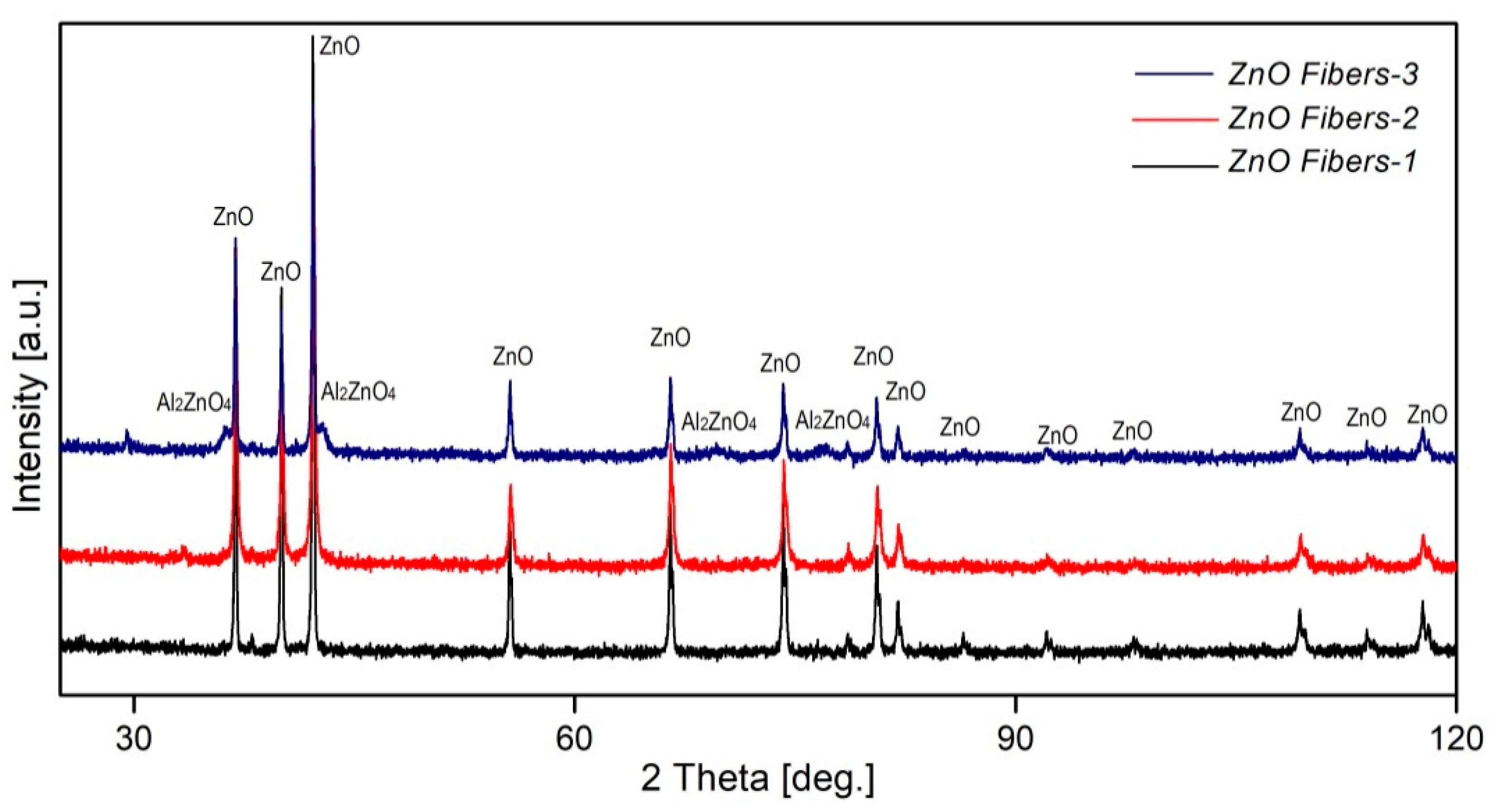
The crystalline character of all ceramic fibers prepared by recycling waste using different leaching media and followed by calcination in air was confirmed by XRD diffraction (Figure 2). The samples ZnO Fibers-1 and ZnO Fibers-2 had a single-phase structure consisting of ZnO (2θ = 36.9°; 38.0°; 40°; 42.2°; 55.6°; 66.5°; 74.2°; 78.6°; 80.6°; 82°; 86.4°; 92.2°; 98.1°; 109.3°; 113.9°; 117.7°; ICOD 01-079-0208), with a grain size of approximately 0.5 µm and 64 nm, respectively, calculated by the Rietveld method. In the ZnO Fibers-3 sample, XRD analysis determined the presence of two phases: (1) the coarse-grained ZnO phase with an average grain size of 190 nm, defined by sharp, high peaks, and (2) the fine-grained Al2ZnO4 phase (2θ = 36.2°; 42.5°; 69.7°; 76.9°; ICOD 01-074-1138) formed by grains with an average size of 30 nm, characterized by broader and less intense peaks, indicating its smaller crystallites size and fine particulate nature.
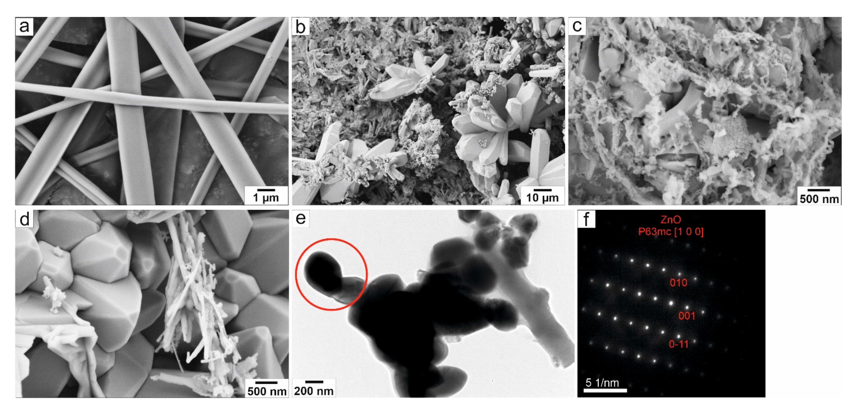
Prepared precursor and ceramic fibers were morphologically analyzed using SEM and TEM. Figure 3 shows the ZnO Fibers-1 and their precursors prepared using HCl as a leaching medium. Precursor fibers (Figure 3a) prepared by needleless electrospinning were considerably heterogeneous and had average diameter values in the interval from 500 nm to 2 μm. After sintering at a temperature of 600 °C with a 60 min dwell time, two types of structures were found in the sample. Large rod-shaped monocrystals with a length of up to 10 μm and fine ceramic polycrystalline fibers with a thickness of approximately 100 nm, as shown in Figure 3b–d. TEM analysis from the relevant area (Figure 3e,f) confirmed that the material is a ZnO phase, in perfect agreement with the XRD analysis.
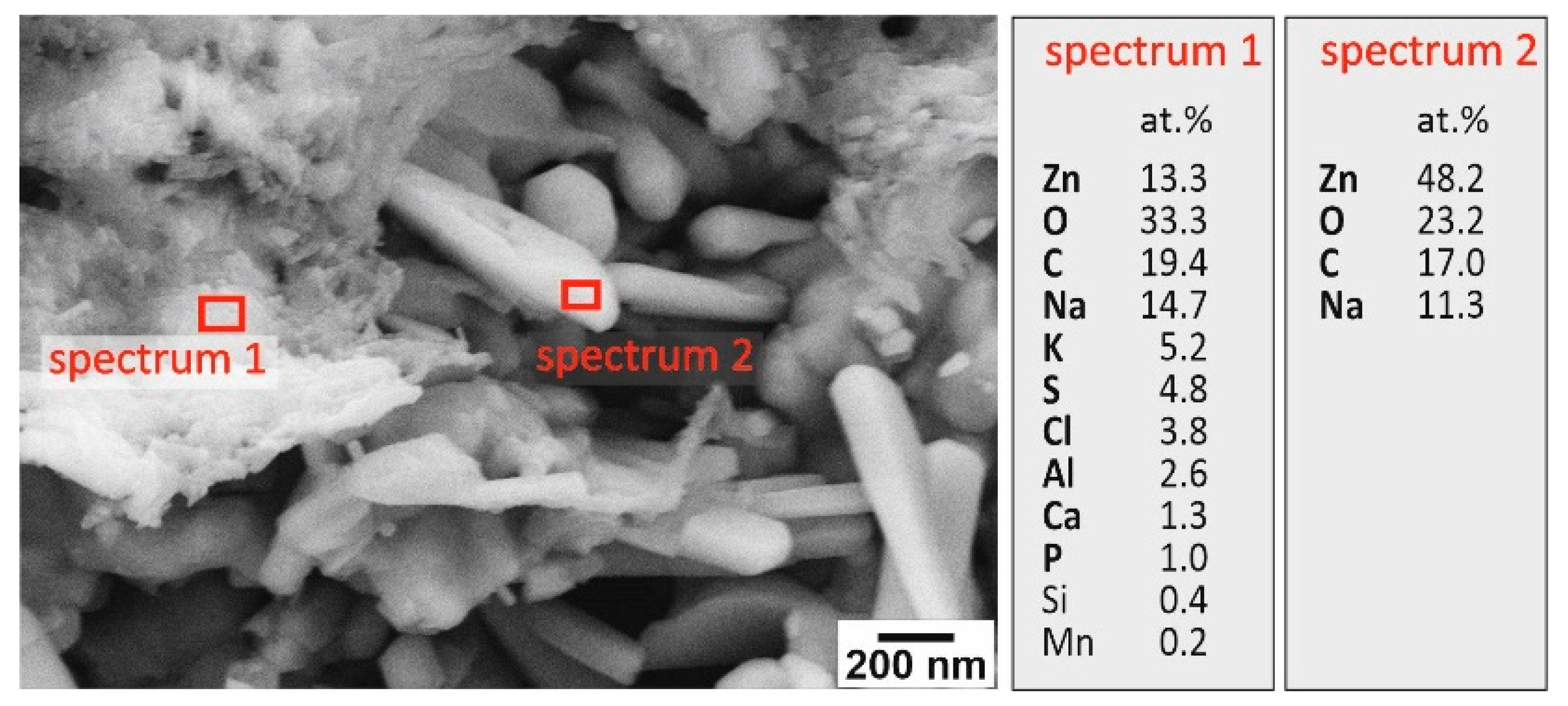
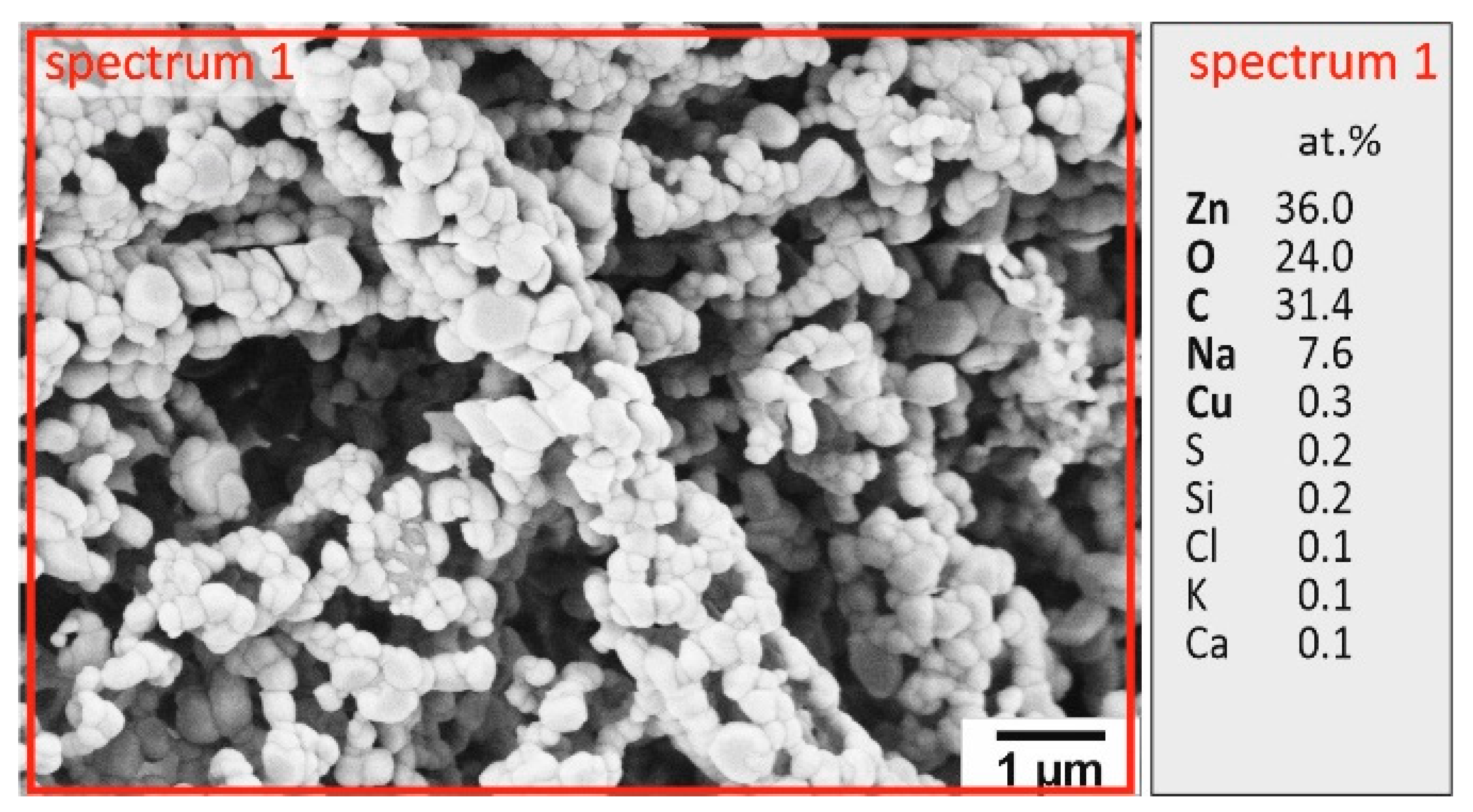
The detailed EDX analysis (Figure 4) revealed that rod-shaped ZnO single crystals contained minor impurities derived from the recycled material. These formations likely resulted from the preferential growth of appropriately oriented ZnO grains. Conversely, the finer ZnO fiber structures exhibited a higher concentration of other elements, potentially hindering further grain growth. The heat-treatment conditions (temperature and dwell time) were optimized. Figure 5 shows that while a temperature of 600 °C for 10 min preserved the fiber structure, the high atomic percentage of carbon (at% C) and low atomic percentage of zinc and oxygen (at% Zn, O) indicated incomplete removal of polymer residues from the precursor fibers. Extending the dwell time to 60 min was necessary, although rod-shaped single crystals had already formed at 40 min. However, even with the extended dwell time, the complete removal of polymer residues from the precursors and the prevention of preferential growth of appropriately oriented ZnO grains were not achieved. A similar phenomenon was observed during the optimization of the calcination temperature.
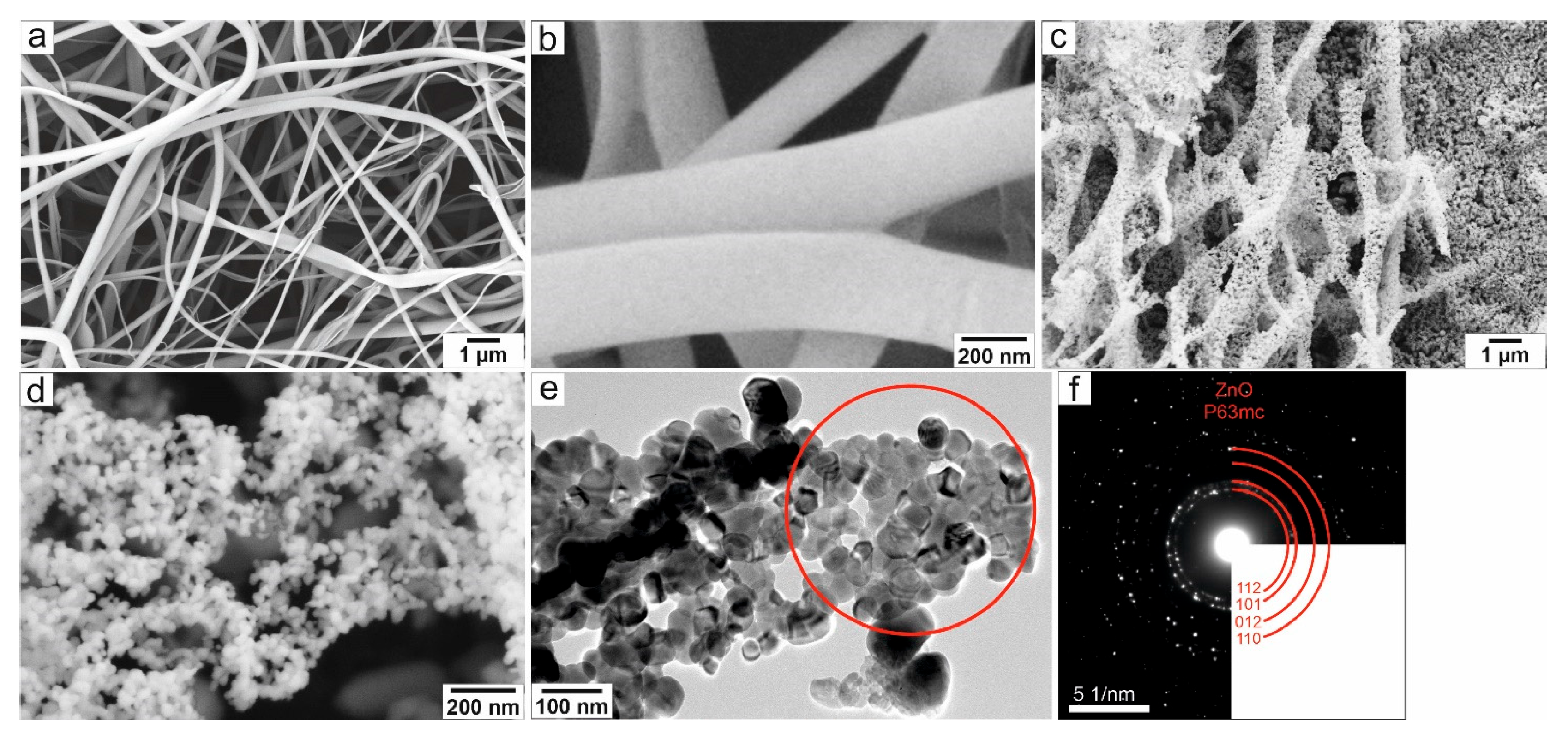
The ZnO Fibers-2, derived from recycled waste using (NH4)2CO3 as a leaching agent, exhibited a significantly different morphology (Figure 6). The thin precursor fibers possessed a smooth surface and a thickness of up to 300 nm (Figure 6a,b). After calcination, the resulting ZnO fibers retained their fibrous structure and achieved high porosity (Figure 6d,e). The fine-grained morphology, consisting of 20–110 nm single-phase ZnO grains, was confirmed by selected-area electron diffraction (Figure 6e,f).
The resulting porous structure of ZnO Fibers-2 was likely caused by the generation of internal porosity of the precursor fibers in the initial stages of the calcination. The corresponding precursor solution was composed of (NH4)2CO3, and after adding acetic acid to the spinning solution, these components reacted to form CO2 gas and ammonium acetate—NH4(CH3COO). Both ammonium carbonate and ammonium acetate may act as gas generators—they decompose at lower temperatures (58 and 165 °C, respectively) with the formation of gaseous products, which may improve the porosity of the final ceramic fibers. This resulted in the formation of internal pores and, after calcination, the formation of a fine-grained porous structure of ZnO Fibers-2. The produced ZnO Fibers-2 contained trace amounts of other elements (Figure 7), which also contributed to the inhibition of grain growth during calcination throughout the entire fiber volume.
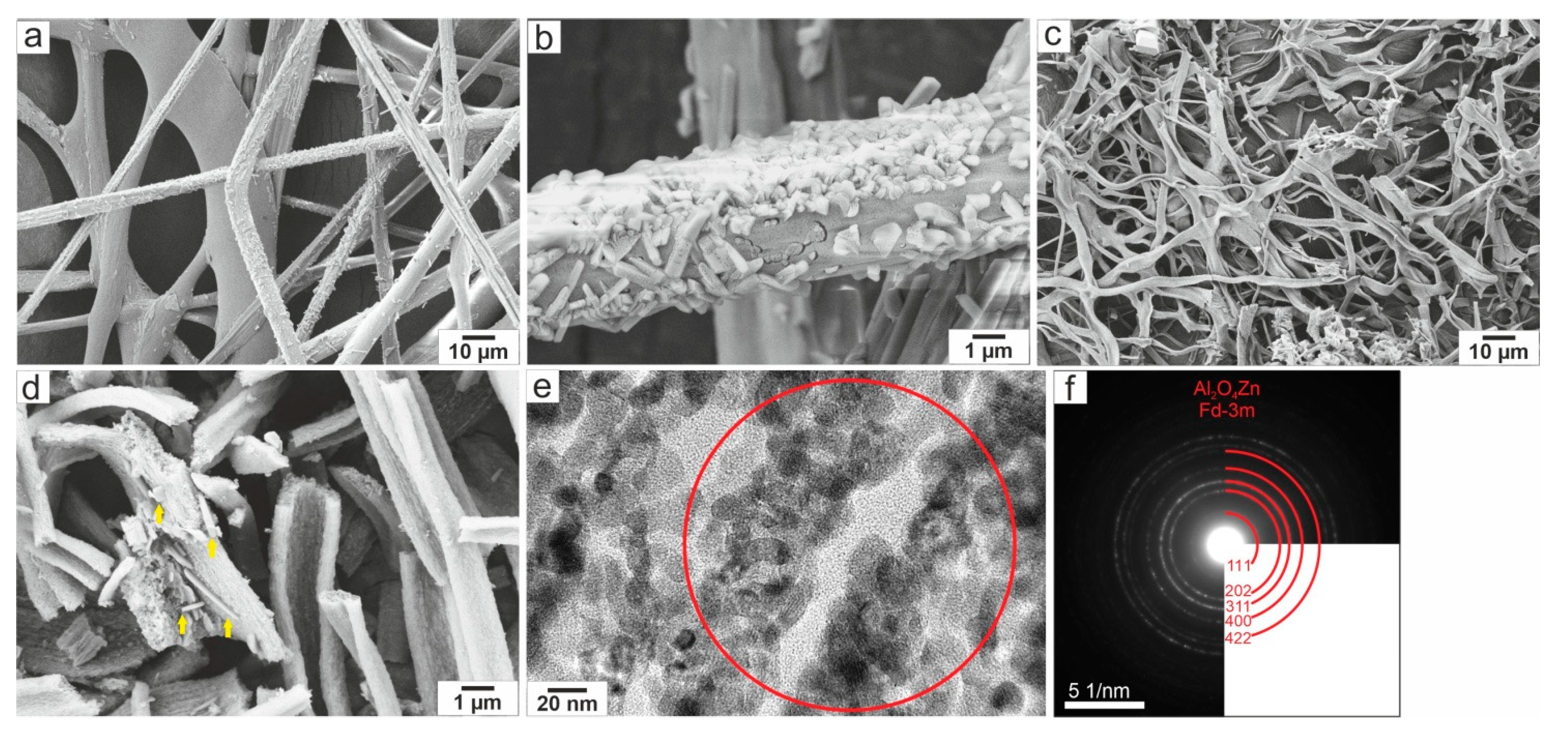
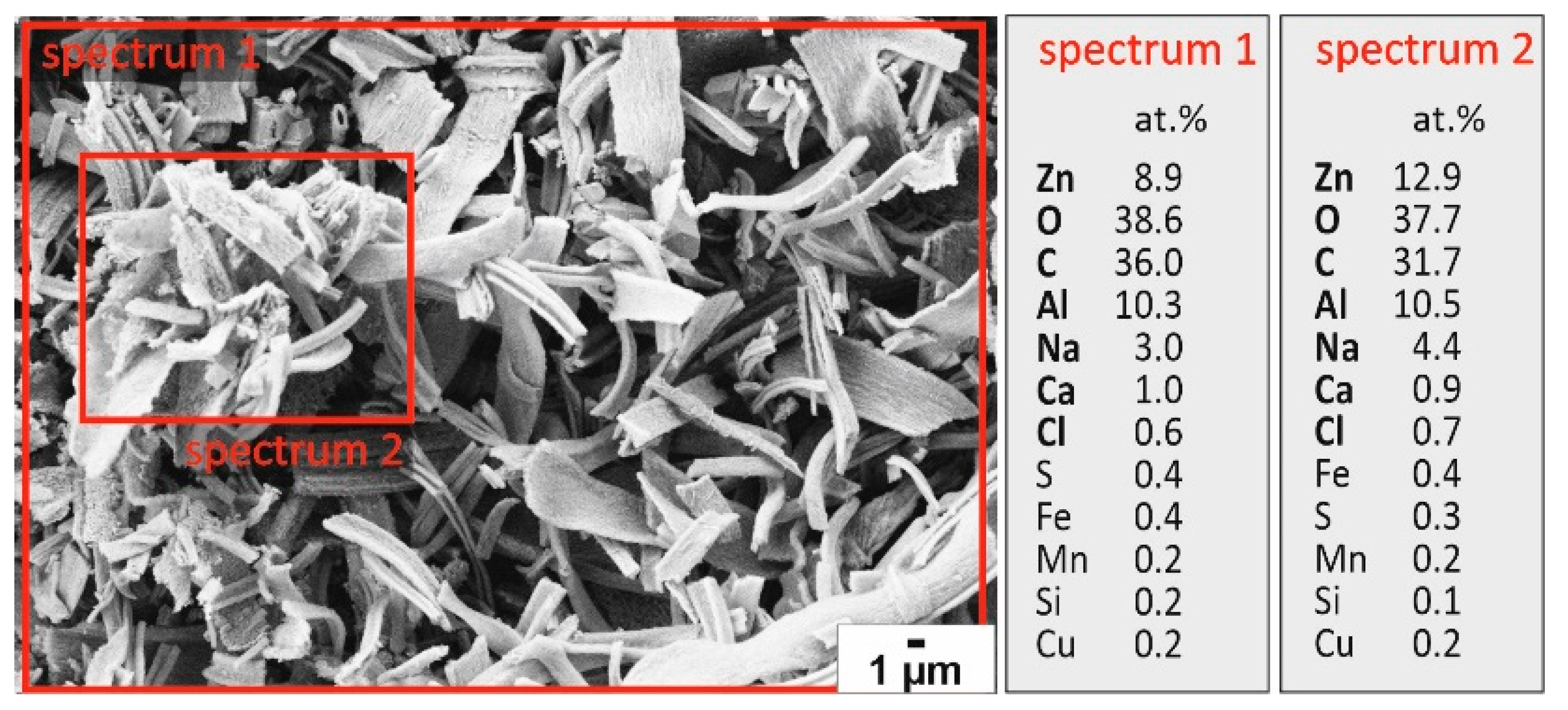
The third type of ZnO fibers was prepared using Zn-enriched leachate-3, which is based on H2SO4. It was obtained by the calcination of precursor fibers, depicted in Figure 8a,b. These were heterogeneous fibers with a thickness in a wide range from 2 to 20 μm. Moreover, as is evident from the detail of the surface of the precursor (Figure 8b), some fibers were covered with fine rod-like formations on the surface. Subsequent calcination at a temperature of 600 °C and a 60 min dwell time resulted in the formation of a fine fibrous network with flat or porous tape-shaped fibers (Figure 8c,d). At the same time, the structure was also made up of several rod-shaped structures, which are marked in Figure 8d. TEM analysis (Figure 8f) showed that tapes with a thickness of about 2 μm were formed by fine Al2ZnO4 grains (approx. 60 nm) and constituted the majority of the ZnO Fibers-3 sample. Likewise, the surface EDX analysis (Figure 9) confirmed a high amount of aluminum in the entire fiber volume. By combining XRD and TEM analysis results, it is possible to state that the final fibers consisted mostly of a fine-grained, fibrous, highly porous Al2ZnO4 phase, while the needle-like ZnO constituted the minority.
The reason for the formation of the new Al2ZnO4 phase is the relatively high amount of Al in the precursor Zn-based Spinning Solution-3 and the pH change during the mixing of the solution with the polymer, which caused some precipitation of Zn. As a result, the Zn-based Spinning Solution-3 was partially depleted of Zn, the Zn/Al ratio was shifted, and thus most of the Zn was consumed in the formation of a major Al2ZnO4 phase.

3.2. Characterization of the Photocatalytic Activity of Ceramic ZnO Fibers

The photocatalytic activities of ZnO fibers, prepared by recycling waste, can be tested for the degradation of methylene blue (MB) dye under UV light irradiation. The use of methylene blue as a test for photocatalytic activity is common in research Therefore, MB was utilized both as a standard and a focused pollutant in need of removal [44].
The ISO 10678:2010 standard, titled “Determination of photocatalytic activity of surfaces in an aqueous medium by degradation of methylene blue,” provides a method to measure the activity of photocatalytically active surfaces. The standard uses an artificial UVA light source (320–400 nm) to irradiate the sample and a methylene blue solution, and the photobleaching of the dye is measured spectrophotometrically to determine the photocatalytic activity. The test is not intended for evaluating photocatalytic activity under visible light [44,45].
Methylene blue, a thiazine dye also known as basic blue 9, is widely used in various industries. It is a cationic dye used for coloring fabrics like cotton, silk, and wool, as well as paper and leather. It also has a history in medicine for treating conditions like methemoglobinemia, and as a diagnostic and antiseptic tool. Its versatility leads to its frequent presence in industrial wastewater [44,45,46].
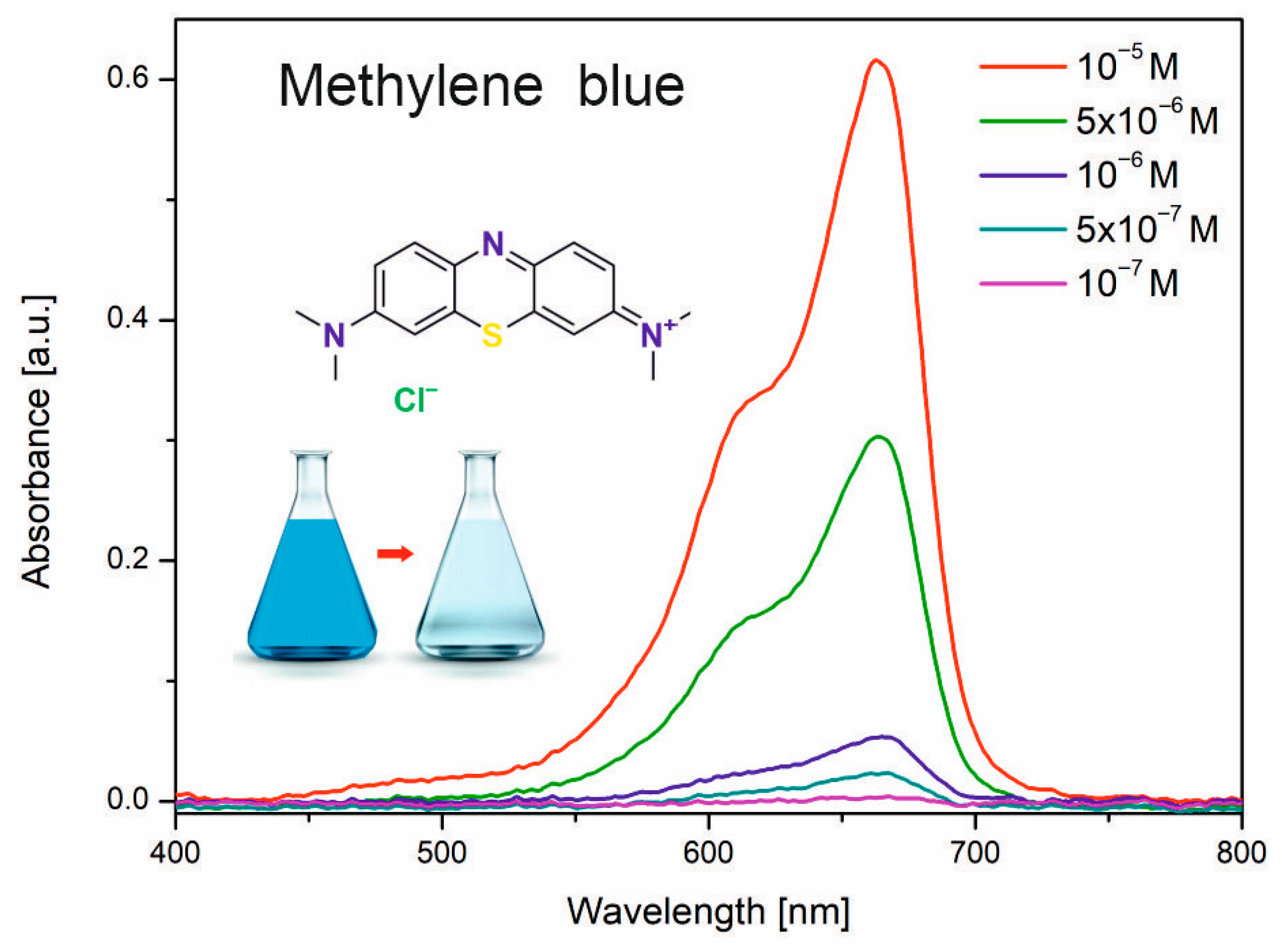
In its untreated form, MB is a significant environmental and health concern. It is classified as toxic, carcinogenic, and non-biodegradable under normal conditions. Its release into natural water sources can block sunlight and harm aquatic life, and it poses a threat to both aquatic organisms and humans. Exposure to high concentrations can cause respiratory problems and organ disorders, underscoring the need for effective degradation and removal methods [44,45,46]. UV–visible absorbance spectra of methylene blue solutions with different concentrations are shown in Figure 10.
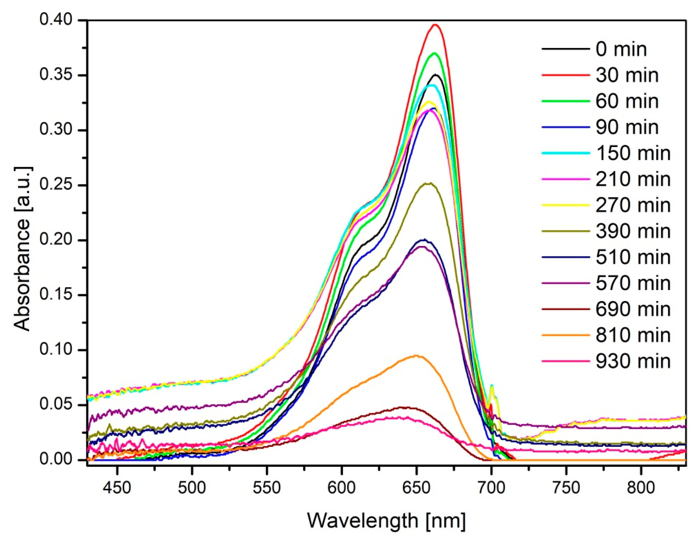
Figure 11 illustrates that the characteristic absorption peak of MB molecules at 662 nm in an aqueous solution diminishes and almost completely disappears after 930 min of irradiation in the presence of 500 mg of ZnO Fibers-1. These results are the best obtained for the materials studied in this work.
The large specific surface area of the ZnO fibers enables more light to be utilized, along with the targeted species being adsorbed. Thus, modification of the porosity and surface area would result in higher catalytic activity. Differences in the photocatalytic efficiencies of the studied materials (described below) can also be partially explained by the differences in the morphology, structure, and phase composition of the fibers, surface area, and overall amount of the used ZnO photocatalyst. Based on the literature [25,34], an increase in the catalyst-to-targeted-substance ratio, i.e., dosage of the utilized photocatalyst, is one of the important parameters dictating the overall efficiency of the decontamination/degradation processes. In this case, as a result, the amount of generated hydroxyl and superoxide radicals also increases, which consequently facilitates the degradation of the organic pollutants. However, the efficiency of photodegradation declines at higher loadings when the photocatalyst dosage is beyond the optimum concentration. This can be ascribed to the light-scattering and screening effects. Moreover, high catalyst dosage facilitates particle–particle interaction and agglomeration in the case of nanoparticles, leading to a reduction in active surface area available for light absorption and pollutant adsorption, which, in turn, reduces the photocatalytic efficiency. On the other hand, the solution turbidity also increases, which inhibits the penetration of light into the solution. Thus, the photoactivated volume of the suspension decreases and consequently lowers the degradation rate. These observations suggest that an optimum dosage should be evaluated to avoid the usage of excess catalyst and to ensure maximum light utilization [25].
To evaluate the dye removal efficiency of the prepared ZnO fibers, it was necessary to find the optimal catalyst-to-dye ratio (targeted substance), so a series of photocatalytic tests was performed at different catalyst amounts: 50 mg, 200 mg, and 500 mg with the same 50 mL of 10−5 M MB at room temperature. The obtained results were processed into dye degradation profiles and presented in Figure 12. The initial test duration was set to 690 min; however, additional time points were recorded for more detailed characterization of the prepared materials’ photocatalytic potential. All the recorded data are presented in Figure 12 and Figure 13 and Table 2.
Figure 12 depicts the photocatalytic efficiency (dye degradation profiles) of the different types of prepared fibers at a fixed catalyst-to-dye ratio, while Figure 13 visualizes the impact of the increase in the catalyst-to-dye ratio within one type of fiber on the degradation efficiency.
The point at −60 min refers to the original state of the system, before the start of the photocatalysis, which is why the value is 0. Optical absorbance measured at 0 min (after addition of the catalyst and reaching the adsorption–desorption equilibrium, without light irradiation) is the initial point in the photocatalytic tests. In all cases, about 8 to 19% of the MB was removed from the solution by adsorption on ZnO fibers, depending on the type of fibers used and the catalyst-to-dye ratio. The precise values can be found in Table 2. Such behavior is typical for nanostructured materials, and ZnO is not an exception [43]. It may also serve as a reference point for the comparison of the sorption ability of the materials. It is not suitable for the calculation of the surface area, because the obtained value will be for a particular cationic dye molecule at a particular pH. Here, the sorption is influenced by the ionic nature of the dye and the ZnO surface charge. However, in the case of comparison of the same material with the same dye, it can be used to state that ZnO Fibers-1 were able to adsorb the most MB among the synthesized ZnO fibers here, probably due to the larger surface area.

4. Discussion

The mechanism of MB degradation by ZnO is already well-known and described in the literature; therefore, it will not be described here in detail [43]. For clarity, photolysis of MB under the experimental conditions, without the catalyst (blank experiment), was studied, and the values were negligible. The profiles of photolysis of pristine MB dye can be seen in Figure 12 and Figure 13. What is more important is the proof of concept that materials derived from cheap raw inputs, i.e., industrial waste, show great potential for the degradation of dyes, and MB in particular.
ZnO Fibers-1 and ZnO Fibers-2, as is evident from Figure 12, showed somewhat comparable photocatalytic activity toward the decomposition of MB at lower catalyst-to-dye ratios (50 mg/50 mL and 200 mg/50 mL), while ZnO Fibers-1 had slightly higher activity, as can be seen from the steeper profile, and was able to remove more dye in the same time. The shape and scatter in Figure 11 at a catalyst loading of 50 mg/50 mL indicate the instability of the process and that it is necessary to increase the photocatalyst amount. At a higher catalyst-to-dye ratio of 200 mg/50 mL, both ZnO Fibers-1 and ZnO Fibers-2 reached the maximum dye degradation efficiency of about 87% at 570 min. On the other hand, a higher value of degradation efficiency was achieved by ZnO Fibers-1 in a slightly longer time, 91% at 690 min. Dye degradation values recorded at the time point of 690 min will be used as a reference value, the benchmark for the overall comparison of the prepared materials.
In the case of ZnO Fibers-3, the efficiency was significantly lower, and the overall performance of the material was the lowest among the prepared ZnO fibers. For the experiments performed with 50 mg of photocatalyst ZnO Fibers-3, it appears that the concentration of the photocatalyst is too low and its presence has no effect on the degradation of MB. However, at a higher catalyst-to-dye ratio of 500 mg/50 mL, the shape and the slope of the curve already show a positive trend. ZnO Fibers-3 were able to remove a smaller amount of MB (~60% at 690 min) as compared to ZnO Fibers-1 (about 83%). At an increased catalyst-to-dye ratio of 500 mg/50 mL, the MB dye was completely removed (100%) within 690 min by ZnO Fibers-1.
The results of the study [47] demonstrated that zinc oxide coatings with the addition of aluminum applied by plasma spraying achieved high photocatalytic activity in the degradation of methylene blue. After deposition, the structure of the composite coating was formed by a mixture of powdered nanosized ZnO and 3 wt. % Al2O3. The authors stated that Al can replace Zn in the Zn lattice, i.e., no new phase was formed, only doping occurs, but plasma spraying results in significant recrystallization and microstructure change. They reported that for Al-doped ZnO coatings deposited by plasma spraying, the maximum efficiency of MB degradation was reduced by 4% with Al doping. Another study [48] reported that the addition of 5 wt.% of Al can change the surface morphology of the coatings and increase the photocatalytic activity. However, in this case, it was for the degradation of methyl orange dye. The aluminum-doped ZnO film was studied in detail. The incorporation of aluminum into the zinc oxide matrix resulted in a slight increase in the optical band gap of ZnO:Al (3.26 eV) compared to the pure ZnO film (3.23 eV). In that study as well, due to the incorporation of aluminum, another phase was not present. The aluminum-doped ZnO film degraded almost all the dye (about 90%) in only 180 min, while the undoped ZnO film reached the same value after almost 300 h of illumination. Likewise, M. Ahmad et al. [49] described that the ZnO photocatalyst doped with 4.0 mol% Al exhibited fivefold enhanced photocatalytic activity compared to pristine ZnO. The enhanced photocatalytic activity could be attributed to extended visible-light absorption, inhibition of electron–hole recombination, and enhanced adsorption of methyl orange dye molecules on the surface of ZnO:Al nanopowders. The increase in Al content from 0.5 to 4.0 mol% effectively increased the degradation efficiency. However, further increases in Al decreased the photocatalytic activity. The optimal concentration of Al doping was found to be 4.0 mol% [49]. In photocatalytic systems, Al deposited on the ZnO surface increased the photocatalytic activity by accelerating the transfer of electrons to dissolved oxygen molecules, so the superoxide anion radical was generated as a result of oxygen reduction by the transfer of trapped electrons from Al to oxygen. Consequently, the recombination of the photo-generated carriers was effectively suppressed, leading to an increase in the photo-oxidation efficiency [49]. In all these cases, the ZnO doping occurred without the formation of a new crystalline phase. In our experiments, it was shown that a high amount of aluminum in the spinning solution results in a significant reduction in photocatalytic activity (see Figure 12). However, it should be noted that zinc aluminate has attracted significant attention in recent years as an advanced material due to its combination of desirable properties: high mechanical strength, high thermal and chemical stability, low sintering temperature, low surface acidity, wide band gap, and excellent optical properties, which may pave the way for application in other fields like high-temperature materials, sensors, electronic and optical materials, as well as catalysts and catalyst supports in organic synthesis [50].
On the contrary, the ZnO Fibers-1 contain trace amounts of elements such as Na, K, Al, S, and Mn, which may act as passive dopants and thus modify the material’s properties. This is consistent with the findings reported in [25] that the photodegradation efficiency of multiple-dopant ZnO is higher than that of pure and single-dopant ZnO systems. When comparing the dye degradation of all three samples at different concentrations, it can be stated that cost-effective ZnO Fibers-1 and ZnO Fibers-2 obtained from industrial waste products showed the highest photocatalytic activity and therefore are suitable for applications in wastewater treatment.
This work aimed to confirm that industrial waste is a viable and sustainable source for producing functional ZnO-based photocatalysts, suitable for industrial-scale applications. While the photocatalytic activity of these ZnO nano/microfibers might be lower than that of commercially available options like Aeroxide P25 TiO2, their benefits significantly outweigh this drawback.
The key advantages of these waste-derived ZnO materials include their low cost and low toxicity. Furthermore, their unique fibrous morphology eliminates mechanically induced toxicity, a common concern with nanoparticles. This fibrous form also offers a practical solution for easier and more cost-effective separation, removing the need for expensive nanofiltration processes often required for powdered catalysts. Even in the unlikely event of catalyst elution into the environment, ZnO’s amphoteric nature ensures its biocompatibility and degradability, which may allow uptake by living organisms [51,52].

5. Conclusions

  • In this work, three types of photocatalytically active ZnO fibers were successfully prepared from industrial waste products using three different leaching media: alkaline ((NH4)2CO3) and acidic (HCl, and H2SO4).
  • The fibers were analyzed in detail using SEM, TEM, and XRD techniques, and their photocatalytic activity was tested by the common dye decolorization method, under the following conditions: 26 W UVA lamp with 365 nm irradiation wavelength, 50 mL of 10−5 M of methylene blue dye.
  • The sample ZnO Fibers-1, formed by a mixture of doped nanofibers and pure ZnO micrograins, had excellent photocatalytic properties at higher catalyst-to-dye ratios—approaching 100% efficiency at 690 min of irradiation time. By contrast, the fine fibers of ZnO Fibers-2 showed better results at lower catalyst-to-dye ratios. The sample ZnO Fibers-3 had impaired photocatalytic properties due to the Zn depletion and the formation of a separate Al2ZnO4 phase. This is due to the high aluminum content in the input waste product, which is the biggest disadvantage of using recycled raw materials.
  • The most suitable material, evaluated based on its photocatalytic activity, was zinc oxide fibers prepared from industrial waste leached in 0.01 M HCl, which were further electrospun and calcined at 600 °C for 1 h.
  • The production of electrospun ZnO fibers from industrial waste products is important because of the acquisition of low-cost input material. At the same time, the added value is the reduction of environmental pollution and the creation of a new product with high added value.
  • Among the main advantages of the application of ZnO-based nanofibers for photocatalytic wastewater treatment are low toxicity; antibacterial nature; low price due to recycling of waste materials; simple separation from the reactive media thanks to the fibrous morphology; and partial biodegradability of ZnO-based materials, which makes Zn bioavailable to living organisms.

Author Contributions

Conceptualization, I.S. and J.P.; formal analysis, I.S.; investigation, K.N., M.L., F.K., and O.P.; methodology, J.K. and A.K.; supervision, E.M.; validation, J.P.; visualization, K.K.; writing—original draft, E.M. and I.S.; writing—review and editing, D.O. All authors have read and agreed to the published version of the manuscript.

Funding

This work was supported by the Scientific Grant Agency of the Ministry of Education, Science, Research, and Sport of the Slovak Republic and the Slovak Academy of Sciences (project no. VEGA 2/0080/23), and by the Slovak Research and Development Agency under contract no. APVV-20-0299. It was also funded by the EU NextGenerationEU through the Recovery and Resilience Plan for Slovakia (project no. 09I03-03-V02-00013).

Institutional Review Board Statement

Not applicable.

Informed Consent Statement

Not applicable.

Data Availability Statement

The original contributions presented in this study are included in the article. Further inquiries can be directed to the corresponding author.

Conflicts of Interest

The authors declare no conflicts of interest.

References

  1. Takacova, Z.; Piroskova, J.; Miskufova, A.; Vindt, T.; Hezelova, M.; Orac, D. Removal of Impurities from EAFD Ammonium Carbonate Leachate and Upgrading the Purity of Prepared ZnO. Materials 2023, 16, 5004. [Google Scholar] [CrossRef] [PubMed]
  2. EAF Dust Recycling Market Size-Forecast to 2032|Report. Available online: https://www.businessresearchinsights.com/market-reports/eaf-dust-recycling-market-108880 (accessed on 25 November 2024).
  3. Al-Harahsheh, M.; Al-Nu’Airat, J.; Al-Otoom, A.; Al-Hammouri, I.; Al-Jabali, H.; Al-Zoubi, M.; Abu Al’Asal, S. Treatments of Electric Arc Furnace Dust and Halogenated Plastic Wastes: A Review. J. Environ. Chem. Eng. 2019, 7, 102856. [Google Scholar] [CrossRef]
  4. Kaya, M.; Hussaini, S.; Kursunoglu, S. Critical Review on Secondary Zinc Resources and Their Recycling Technologies. Hydrometallurgy 2020, 195, 105362. [Google Scholar] [CrossRef]
  5. Tsakiridis, P.E.; Oustadakis, P.; Katsiapi, A.; Agatzini-Leonardou, S. Hydrometallurgical Process for Zinc Recovery from Electric Arc Furnace Dust (EAFD). Part II: Downstream Processing and Zinc Recovery by Electrowinning. J. Hazard. Mater. 2010, 179, 8–14. [Google Scholar] [CrossRef] [PubMed]
  6. Teo, Y.Y.; Lee, H.S. Improved Hydrometallurgical Extraction of Zinc and Iron from Electric Arc Furnace (EAF) Dust Waste Using Hydrochloric Acid. In AIP Conference Proceedings; AIP: Perak, Malaysia, 2019; Volume 2157, p. 20017. [Google Scholar]
  7. Langová, Š.; Leško, J.; Matýsek, D. Selective Leaching of Zinc from Zinc Ferrite with Hydrochloric Acid. Hydrometallurgy 2009, 95, 179–182. [Google Scholar] [CrossRef]
  8. Binnemans, K.; Jones, P.T.; Manjón Fernández, Á.; Masaguer Torres, V. Hydrometallurgical Processes for the Recovery of Metals from Steel Industry By-Products: A Critical Review; Springer International Publishing: Manhattan, NY, USA, 2020; Volume 6, ISBN 0123456789. [Google Scholar]
  9. Zoraga, M.; Ilhan, S.; Kalpakli, A.O. Leaching Kinetics of Electric Arc Furnace Dust in Nitric Acid Solutions. Int. J. Chem. Kinet. 2020, 52, 933–942. [Google Scholar] [CrossRef]
  10. Halli, P.; Hamuyuni, J.; Leikola, M.; Lundström, M. Developing a Sustainable Solution for Recycling Electric Arc Furnace Dust via Organic Acid Leaching. Miner. Eng. 2018, 124, 1–9. [Google Scholar] [CrossRef]
  11. Halli, P.; Agarwal, V.; Partinen, J.; Lundström, M. Recovery of Pb and Zn from a Citrate Leach Liquor of a Roasted EAF Dust Using Precipitation and Solvent Extraction. Sep. Purif. Technol. 2020, 236, 116264. [Google Scholar] [CrossRef]
  12. Leclerc, N.; Meux, E.; Lecuire, J.M. Hydrometallurgical Extraction of Zinc from Zinc Ferrites. Hydrometallurgy 2003, 70, 175–183. [Google Scholar] [CrossRef]
  13. Miki, T.; Chairaksa-Fujimoto, R.; Maruyama, K.; Nagasaka, T. Hydrometallurgical Extraction of Zinc from CaO Treated EAF Dust in Ammonium Chloride Solution. J. Hazard. Mater. 2016, 302, 90–96. [Google Scholar] [CrossRef]
  14. Pirošková, J.; Klimko, J.; Trpčevská, J.; Laubertová, M.; Plešingerová, B.; Liptai, P.; Vindt, T.; Oráč, D. Characterization of Galvanizing Flue Dust and Recycling Possibilities. Metals 2022, 12, 744. [Google Scholar] [CrossRef]
  15. Pirošková, J.; Klimko, J.; Ružičková, S.; Laubertová, M.; Marcinov, V.; Múdra, E.; Vojtko, M.; Oráč, D. Utilization of Galvanizing Flue Dust Residue: A Sustainable Approach towards Complete Material Recycling. Metals 2024, 14, 253. [Google Scholar] [CrossRef]
  16. Cook, T.H. Composition, Testing, and Control of Hot Dip Galvanizing Flux. Met. Finish. 2003, 101, 22–35. [Google Scholar] [CrossRef]
  17. Leychkis, D.; Zervoudis, J. Flux and Process for Hot Dip Galvanization Flussmittel. EP 1 974 070 B1, 2010. Available online: https://lens.org/012-240-725-392-688 (accessed on 25 August 2025).
  18. Rahman, L.; Quddus, S.; Khanam, J.; Bilkis, K.; Rahman, M. Fabrication of Zinc Oxide from Zinc Dust and Its Characterization. IOSR J. Appl. Chem. 2017, 10, 21–26. [Google Scholar] [CrossRef]
  19. Bisol, F. Process for Treating Metallic Dust, Mostly Oxididised Waste in Particular Galvanising Dust and/or Steelworks Smoke. US 4169776 A, 1998. Available online: https://lens.org/073-460-353-409-131 (accessed on 25 August 2025).
  20. Piroskova, J.; Trpcevska, J.; Orac, D.; Laubertova, M.; Horvathova, H.; Holkova, B. Production of Zinc Oxide from Hazardous Waste - Sal Ammoniac Skimming. J. Min. Metall. Sect. B Metall. 2018, 54, 377–384. [Google Scholar] [CrossRef]
  21. Krištofová, D. Recyklace Neželezných Kovů; Skripta VŠB-TU Ostrava: Ostrava, Czech Republic, 2003. (In Czech) [Google Scholar]
  22. Dvořák, P.; Jandová, J. Hydrometallurgical Recovery of Zinc from Hot Dip Galvanizing Ash. Hydrometallurgy 2005, 77, 29–33. [Google Scholar] [CrossRef]
  23. Eddleman, W.L. Method for Recovery of Metallic Zinc from Chlorine Contaminated Skimmings. U.S. Patent 4,169,776, 2 October 1979. [Google Scholar]
  24. Tercero Espinoza, L.A. Critical Appraisal of Recycling Indicators Used in European Criticality Exercises and Circularity Monitoring. Resour. Policy 2021, 73, 102208. [Google Scholar] [CrossRef]
  25. Lee, K.M.; Lai, C.W.; Ngai, K.S.; Juan, J.C. Recent Developments of Zinc Oxide Based Photocatalyst in Water Treatment Technology: A Review. Water Res. 2016, 88, 428–448. [Google Scholar] [CrossRef]
  26. Methaapanon, R.; Chutchakul, K.; Pavarajarn, V. Photocatalytic Zinc Oxide on Flexible Polyacrylonitrile Nanofibers via Sol–Gel Coaxial Electrospinning. Ceram. Int. 2020, 46, 8287–8292. [Google Scholar] [CrossRef]
  27. Roy, N.; Chakraborty, S. ZnO as Photocatalyst: An Approach to Waste Water Treatment. Mater. Today Proc. 2019, 46, 6399–6403. [Google Scholar] [CrossRef]
  28. Kosera, V.S.; Cruz, T.M.; Chaves, E.S.; Tiburtius, E.R.L. Triclosan Degradation by Heterogeneous Photocatalysis Using ZnO Immobilized in Biopolymer as Catalyst. J. Photochem. Photobiol. A Chem. 2017, 344, 184–191. [Google Scholar] [CrossRef]
  29. Schmidt-Mende, L.; MacManus-Driscoll, J.L. ZnO-Nanostructures, Defects, and Devices. Mater. Today 2007, 10, 40–48. [Google Scholar] [CrossRef]
  30. Srikanth, B.; Goutham, R.; Badri Narayan, R.; Ramprasath, A.; Gopinath, K.P.; Sankaranarayanan, A.R. Recent Advancements in Supporting Materials for Immobilised Photocatalytic Applications in Waste Water Treatment. J. Environ. Manag. 2017, 200, 60–78. [Google Scholar] [CrossRef] [PubMed]
  31. Sampaio, M.J.; Lima, M.J.; Baptista, D.L.; Silva, A.M.T.; Silva, C.G.; Faria, J.L. Ag-Loaded ZnO Materials for Photocatalytic Water Treatment. Chem. Eng. J. 2017, 318, 95–102. [Google Scholar] [CrossRef]
  32. Liu, J.; Ma, N.; Wu, W.; He, Q. Recent Progress on Photocatalytic Heterostructures with Full Solar Spectral Responses. Chem. Eng. J. 2020, 393, 124719. [Google Scholar] [CrossRef]
  33. Serpone, N.; Maruthamuthu, P.; Pichat, P.; Pelizzetti, E.; Hidaka, H. Exploiting the Interparticle Electron Transfer Process in the Photocatalysed Oxidation of Phenol, 2-Chlorophenol and Pentachlorophenol: Chemical Evidence for Electron and Hole Transfer between Coupled Semiconductors. J. Photochem. Photobiol. A Chem. 1995, 85, 247–255. [Google Scholar] [CrossRef]
  34. Ong, C.B.; Ng, L.Y.; Mohammad, A.W. A Review of ZnO Nanoparticles as Solar Photocatalysts: Synthesis, Mechanisms and Applications. Renew. Sustain. Energy Rev. 2018, 81, 536–551. [Google Scholar] [CrossRef]
  35. Imran, M.; Haider, S.; Ahmad, K.; Mahmood, A.; Al-masry, W.A. Fabrication and Characterization of Zinc Oxide Nanofibers for Renewable Energy Applications. Arab. J. Chem. 2017, 10, S1067–S1072. [Google Scholar] [CrossRef]
  36. Wu, H.; Pan, W. Preparation of Zinc Oxide Nanofibers by Electrospinning. J. Am. Ceram. Soc. 2006, 89, 699–701. [Google Scholar] [CrossRef]
  37. Wang, W.; Huang, H.; Li, Z.; Zhang, H.; Wang, Y.; Zheng, W.; Wang, C. Zinc Oxide Nanofiber Gas Sensors via Electrospinning. J. Am. Ceram. Soc. 2008, 91, 3817–3819. [Google Scholar] [CrossRef]
  38. Thangavel, K.; Balamurugan, A.; Venkatachalam, T.; Ranjith Kumar, E. Structural, Morphological and Optical Properties of ZnO Nano-Fibers. Superlattices Microstruct. 2016, 90, 45–52. [Google Scholar] [CrossRef]
  39. Piroskova, J.; Trpcevska, J.; Smincakova, E.; Holkova, B.; Laubertová, M.; Horvathova, H. Kinetic Study of Zinc Leaching from Flux Skimming. Metall 2016, 70, 28–32. [Google Scholar]
  40. Ajmal, A.; Majeed, I.; Malik, R.N.; Idriss, H.; Nadeem, M.A. Principles and Mechanisms of Photocatalytic Dye Degradation on TiO 2 Based Photocatalysts: A Comparative Overview. RSC Adv. 2014, 4, 37003–37026. [Google Scholar] [CrossRef]
  41. Ramesh, P.; Rajendran, A. Green Synthesis of Manganese Dioxide Nanoparticles: Photocatalytic and Antimicrobial Investigations. Int. J. Environ. Anal. Chem. 2023, 104, 8464–8476. [Google Scholar] [CrossRef]
  42. Prasad, A.R.; Garvasis, J.; Oruvil, S.K.; Joseph, A. Bio-Inspired Green Synthesis of Zinc Oxide Nanoparticles Using Abelmoschus Esculentus Mucilage and Selective Degradation of Cationic Dye Pollutants. J. Phys. Chem. Solids 2019, 127, 265–274. [Google Scholar] [CrossRef]
  43. Venkatesan, S.; Suresh, S.; Ramu, P.; Arumugam, J.; Thambidurai, S.; Pugazhenthiran, N. Methylene Blue Dye Degradation Potential of Zinc Oxide Nanoparticles Bioreduced Using Solanum Trilobatum Leaf Extract. Results Chem. 2022, 4, 100637. [Google Scholar] [CrossRef]
  44. Mills, A. An Overview of the Methylene Blue ISO Test for Assessing the Activities of Photocatalytic Films. Appl. Catal. B Environ. 2012, 128, 144–149. [Google Scholar] [CrossRef]
  45. ISO ISO 10678:2010(En); Determination of Photocatalytic Activity of Surfaces in an Aqueous Medium by Degradation of Methylene Blue. Available online: https://www.iso.org/obp/ui/#iso:std:iso:10678:ed-1:v1:en (accessed on 1 September 2010).
  46. Bistas, E.; Sanghavi, D.K. Methylene Blue. Hist. Mod. Clin. Toxicol. 2023, 231–241. [Google Scholar] [CrossRef]
  47. Su, C.Y.; Lu, C.T.; Hsiao, W.T.; Liu, W.H.; Shieu, F.S. Evaluation of the Microstructural and Photocatalytic Properties of Aluminum-Doped Zinc Oxide Coatings Deposited by Plasma Spraying. Thin Solid Films 2013, 544, 170–174. [Google Scholar] [CrossRef]
  48. Bizarro, M.; Sánchez-Arzate, A.; Garduño-Wilches, I.; Alonso, J.C.; Ortiz, A. Synthesis and Characterization of ZnO and ZnO:Al by Spray Pyrolysis with High Photocatalytic Properties. Catal. Today 2011, 166, 129–134. [Google Scholar] [CrossRef]
  49. Ahmad, M.; Ahmed, E.; Zhang, Y.; Khalid, N.R.; Xu, J.; Ullah, M.; Hong, Z. Preparation of Highly Efficient Al-Doped ZnO Photocatalyst by Combustion Synthesis. Curr. Appl. Phys. 2013, 13, 697–704. [Google Scholar] [CrossRef]
  50. De Macedo, H.P.; De Araújo Medeiros, R.L.B.; De Medeiros, A.L.; De Oliveira, Â.A.S.; De Figueredo, G.P.; De Freitas Melo, M.A.; De Araújo Melo, D.M. Characterization of ZnAl2O4 Spinel Obtained by Hydrothermal and Microwave Assisted Combustion Method: A Comparative Study. Mater. Res. 2017, 20, 29–33. [Google Scholar] [CrossRef]
  51. Šebesta, M.; Kolenčík, M.; Ratna Sunil, B.; Illa, R.; Mosnáček, J.; Ingle, A.P.; Urík, M. Field Application of Zno and Tio2 Nanoparticles on Agricultural Plants. Agronomy 2021, 11, 2281. [Google Scholar] [CrossRef]
  52. Kurtinová, S.; Šebesta, M. Heavy Metal Stress Alleviation in Plants by ZnO and TiO2 Nanoparticles. Nanotechnol. Agric. Agroecosystems 2023, 347–365. [Google Scholar] [CrossRef]
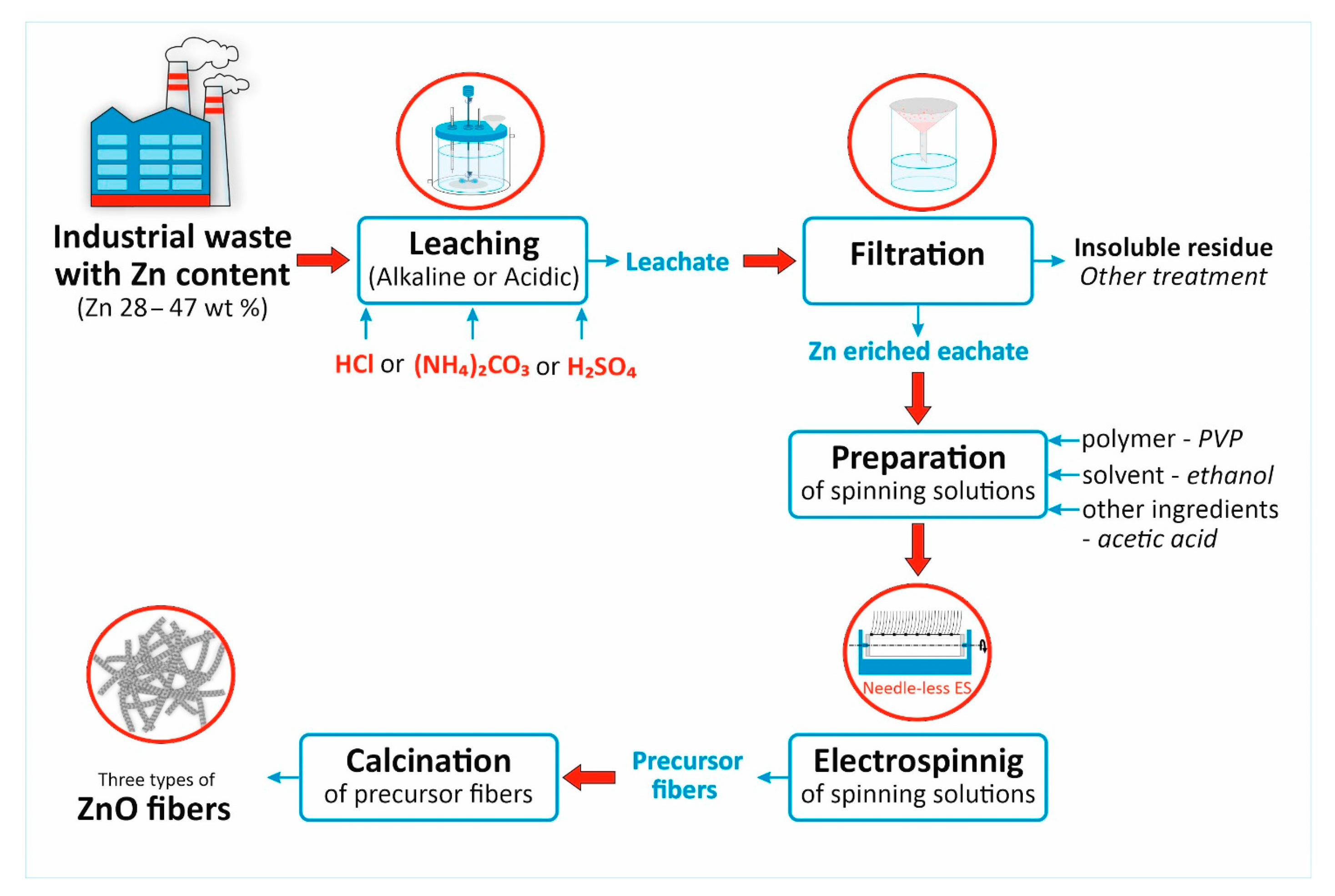
Figure 1. The scheme for the preparation of ZnO fibers.
Sustainability 17 08373 g001
Figure 2. XRD patterns of ZnO fibers prepared by recycling waste in different leaching media.
Sustainability 17 08373 g002
Figure 3. SEM images of (a) precursor fibers; (b) resulting morphology of ceramic ZnO Fibers-1; (c) detail of fine-grained ZnO Fibers-1; (d) detail of coarse-grained ZnO Fibers-1; (e) TEM image of ZnO Fibers-1 with a selected-area electron diffraction, and (f) pattern of the electron diffraction.
Sustainability 17 08373 g003
Figure 4. Point EDX analysis of two different morphologies of ZnO Fibers-1.
Sustainability 17 08373 g004
Figure 5. SEM images with EDX area analysis of developing morphology of ZnO Fibers-1 depending on the dwell time of calcination.
Sustainability 17 08373 g005
Figure 6. SEM images of (a) precursor fibers; (b) detail of precursor fibers; (c) resulting morphology of ceramic ZnO Fibers-2; (d) detail of fine-grained ZnO Fibers-2; (e) TEM image of ZnO Fibers-2 with a selected-area electron diffraction, and (f) pattern of the electron diffraction.
Sustainability 17 08373 g006
Figure 7. Area EDX analysis of ZnO Fibers-2.
Sustainability 17 08373 g007
Figure 8. SEM images of (a) precursor fibers; (b) detail of precursor fibers; (c) resulting morphology of ceramic ZnO Fibers-3; (d) detail of fine-grained ZnO Fibers-3; (e) TEM image of the fine-grained phase of ZnO Fibers-3 with a selected-area electron diffraction, and (f) pattern of the electron diffraction.
Sustainability 17 08373 g008
Figure 9. Area EDX analysis of two different regions of the ZnO Fibers-3 sample.
Sustainability 17 08373 g009
Figure 10. UV–visible absorbance spectra of methylene blue solutions with different concentrations: 10−5 M, 5 × 10⁻⁶ M, 10−6 M, 5 × 10⁻⁷ M, and 10−7 M.
Sustainability 17 08373 g010
Figure 11. UV–visible absorbance spectra of methylene blue dye recorded during its photocatalytic degradation by 500 mg of ZnO Fibers-1 under UV light irradiation.
Sustainability 17 08373 g011
Figure 12. The photocatalytic dye degradation profiles measured for the prepared ZnO fibers at different catalyst amounts: (A) 50 mg; (B) 200 mg; (C) 500 mg of the tested fiber samples in 50 mL of MB under UV radiation.
Sustainability 17 08373 g012
Figure 13. The photocatalytic dye degradation profiles measured for (A) ZnO Fibers-1; (B) ZnO Fibers-2; (C) ZnO Fibers-3 at different catalyst amounts: 50 mg, 200 mg, and 500 mg of the tested fiber samples in 50 mL of MB under UV radiation.
Sustainability 17 08373 g013
Table 1. Chemical composition of the leaching solutions, obtained by AAS analysis.
Origin of the Liquid SampleContent of Elements in Input Recycling Solution [g/L]
ZnPbFeCuAlCrCaSi
Zn-enriched leachate-1:
0.01 M HCl; 50 °C, 30 min
12.320.20.0030.006-0.0010.030.011
Zn-enriched leachate-2:
25 g/L (NH4)2CO3; 20–60 °C, 30 min
33.870.008------
Zn-enriched leachate-3:
0.5 M H2SO4; 20 °C, 30 min
6.820.0970.1320.0042.16---
Table 2. Quantitative evaluation of the photocatalytic efficiency of the prepared ZnO fibers.
ParameterSampleAmount of the Used ZnO Fibers for 50 mL of 10−5 M MB
50 mg200 mg500 mg
Initial dye absorption, %ZnO Fibers-18.513.818.6
ZnO Fibers-29.614.219.5
ZnO Fibers-39.211.112.1
Dye degradation efficiency at 690 min, %ZnO Fibers-161.887.699.4
ZnO Fibers-259.091.183.0
ZnO Fibers-315.045.460.2
Disclaimer/Publisher’s Note: The statements, opinions and data contained in all publications are solely those of the individual author(s) and contributor(s) and not of MDPI and/or the editor(s). MDPI and/or the editor(s) disclaim responsibility for any injury to people or property resulting from any ideas, methods, instructions or products referred to in the content.