1. Introduction
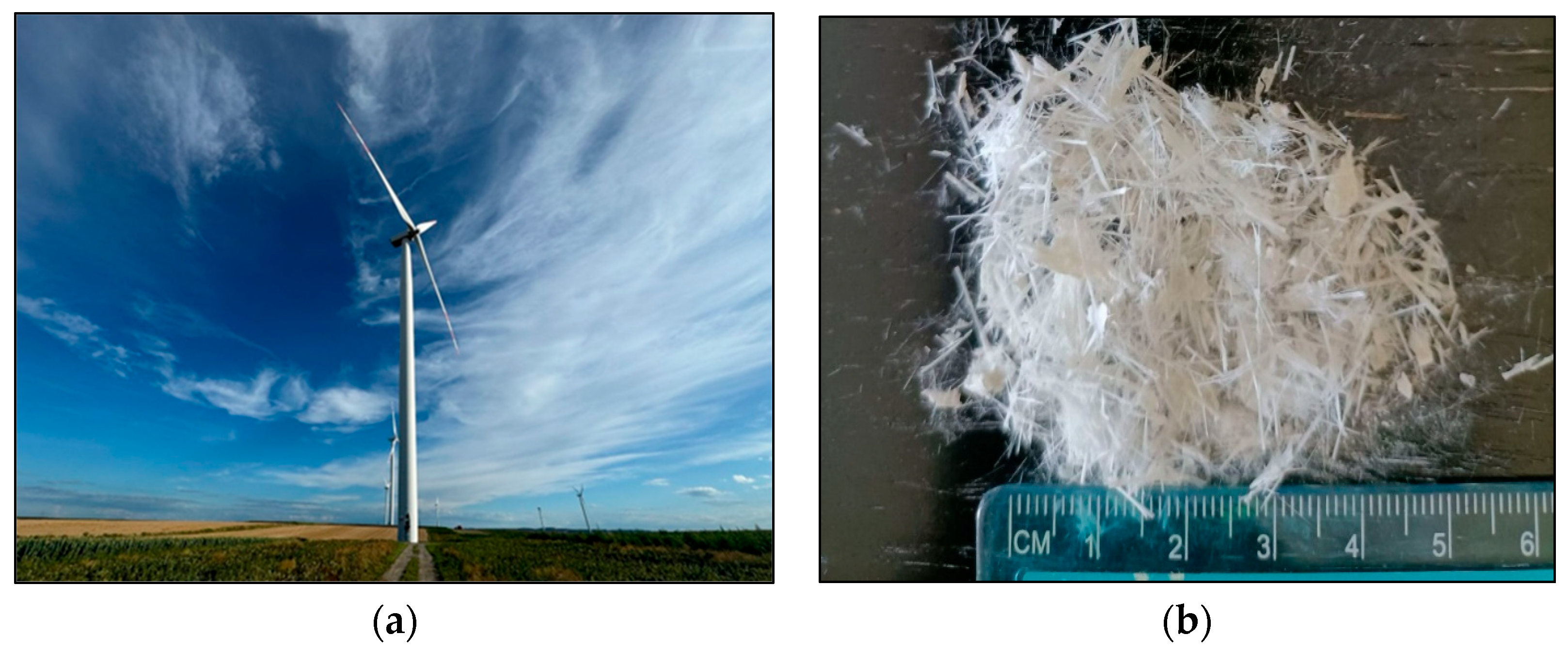
Renewable energy, including wind power, has been expanding rapidly in recent years [
1]. According to World Wind Energy Association (WWEA) Annual Report [
2] global wind power capacity was 371 MW in 2014, and, by 2023, it had surpassed 1 million megawatts (1047 GW). The construction of offshore and onshore wind farms requires mechanically robust materials with sufficient stiffness and wear resistance. One of the key components of wind turbines is the set of three blades manufactured from glass fibre-reinforced polymer (GFRP) composites or carbon fibre-reinforced polymer (CFRP) composites. On average, 93% of the blade is composite material, with the remaining components being PVC—2%; balsa wood—2%; and metal, paint, and putty—3% [
3]. Depending on turbine power, the average blade mass ranges from 8.43 t/MW (power < 1 MW) to 13.41 t/MW (power 2–5 MW). In recent years, however, the mass has been slightly reduced to 12.58 t/MW for turbines above 5 MW [
4]. The reason for the use of fibre-reinforced polymer composites is primarily long life (high durability and weather resistance), high strength to weight ratio and stiffness [
5]. The average lifespan of wind turbines is 20–25 years, and it is estimated that, by 2025, about 36,000 blades will be dismantled in Europe, generating equivalent to 240,000 tons of polymer composite waste [
6].
The mechanical properties of fibre-reinforced polymer composites are highly advantageous and are the main reason for their use in wind turbine blade production. However, these same properties also create challenges during the recovery process. The quality and reusability of the recovered fibres, along with the environmental impact and the processing cost, are significant concerns [
7,
8]. In addition, the financial implications of transporting blades should not be underestimated. As a result, some dismantled blades are prepared for reuse through renovation, refurbishment, and repair [
9]. Following appropriate adaptation, potential application for this material can be found in construction and infrastructure. Wind turbine blades (WTBs) have been proposed for use in power lines, pedestrian bridges, and roofing systems [
4,
10]. Furthermore, WTBs have been documented to be stored [
9].
The concepts of mechanical, chemical, and thermal recycling are often discussed in the literature on WTB recovery. In addition, hybrid methods that combine these recycling techniques are also used [
8].
Mechanical recycling is mainly applicable to GFRPs and involves a sequence of processes such as cutting and grinding to obtain fibres of the desired size or a powder form. Chemical recycling separates fibres from resin under specific pressure and temperature conditions (solvolysis), using chemicals such as alcohols, ketones, or water [
11]. Thermal methods, such as the fluidised bed technique and pyrolysis, are primarily applied to CFRP. The process entails thermal decomposition of the combustible components of the blades under aerobic (combustion) or anaerobic (pyrolysis) conditions, resulting in the release of non-combustible components in the form of fibres that can be reused [
12].
Crushing GFRP to the required sizes enables its use in the construction industry for asphalt, mortar, concrete, or the production of geopolymers. The use of fibreglass in asphalt production has improved the properties of asphalt mixtures at high and low temperatures, rendering them suitable for use in asphalt during compaction, placement, and operation [
13]. Zhen et al. [
14] studied the effect of GFRP powder on asphalt mastic and found that it had a favourable effect on elasticity and rutting resistance at elevated temperatures, but an unfavourable effect on stiffness and the onset of cracking at low temperatures. Similarly, Lan et al. [
15] reported that the addition of up to 10% GFRP powder improved the rutting resistance of asphalt mixtures. The use of GFRP as a filler in geopolymer composites has also been investigated. A general decrease in the properties of the geopolymer composite was observed. Nevertheless, it was found that it is possible to use GFRP in geopolymer composites for the filler content of 5% and 15% of dry mass [
16].
The effects of incorporating GFRP into concrete as a partial replacement of cement or coarse aggregates, or as a fibre reinforcement, were studied by Baturkin et al. [
17]. The use of GFRP powder led to a significant decrease in the compressive and flexural capacity of concrete due to its high organic content (particularly wood). The study showed that the pozzolanic activity index for GFRP powder at 20% replacement of cement was 65, and at 40% replacement of cement was 35. After wood removal, the mix in which 10% of cement was replaced with GFRP powder showed comparable compressive strength to the reference mix. Baturkin et al. [
17] also reported the negative effect of GFRP powder containing wood on the mechanical strength of concrete. When this waste was used as a partial replacement for cement (10%, 20%, and 30%), strength decreased after 28 days, but the removal of wood proved beneficial, mitigating the strength loss. The compressive strength of concrete with 10% powder of GFRP as a cement replacement was comparable to that of the reference concrete. In addition, the authors found that the decrease in compressive strength was insignificant when natural aggregate was replaced with aggregate made from GFRP, even when the aggregates contained wood. A study of the microstructure of GFRP concrete performed on a scanning electron microscope (SEM) [
18] showed the presence of gaps between the matrix and the GFRP aggregate (interfacial transition zone—ITZ), which are the result of shrinkage of the wood as the concrete dries. In addition, aggregates produced from GFRP can have a smooth and slippery surface, which is not conducive to bonding with the cement matrix. In view of this, under axial loading, they tend to separate from the matrix by which the mechanical performance of concretes deteriorates [
17,
18,
19].
The effect of curing conditions of concrete samples with 5, 15, 30, 50% GFRP waste powder as substitute fine aggregate in concrete was presented by Asokan et al. [
20]. The samples were cured in water at 20 °C and in an oven at 50 °C. The compressive strength of the oven-cured specimens was higher than that of the water-cured specimens. The increase in the compressive strength of concrete using GFRP waste during oven-curing may have been due to the hydration process in which the polymer compound from GFRP waste and cement formed a polymer layer. After 180 days of curing, the compressive strength of the concrete with 15% GFRP powder in water-curing was 44.38 MPa and 46.24 MPa in the furnace, while that of the control sample was 46.23 MPa and 39.20 MPa, respectively. In addition to its effect on mechanical parameters, the use of GFRP in concretes was found to increase water demand in order to maintain the target workability [
20].
This article presents preliminary results on the feasibility of using GFRP fibres from decommissioned wind turbine blades as a substitute for natural aggregates in concrete production. Despite the growing number of publications on GFRP recycling, the literature still lacks comprehensive studies that combine microstructural analysis of concrete using advanced imaging techniques with a detailed assessment of the effects of waste fibres on its mechanical and durability properties. To address this gap, in addition to standard compressive and tensile strength tests, X-ray computed tomography (X-ray CT) and other methods were employed. These results made it possible to analyse in detail the spatial distribution of fibres within the concrete structure and to reveal significant microstructural changes, such as increased porosity and the appearance of inhomogeneities.
In addition, watertightness and frost-resistance tests were conducted. These are rarely considered in studies of concretes containing waste fibres but are particularly important for designing structural elements exposed to aggressive environments, such as foundations, bridge components, road structures, and pavements operating in harsh weather conditions. As part of the strength testing, Young’s modulus was also measured, which is not commonly examined in concretes with added waste fibres. The results of these tests are crucial, especially when designing structures using advanced numerical methods, where precise determination of material stiffness is essential for accurate modelling of structural performance.
The proposed approach enables effective management of a difficult-to-process yet increasingly common type of waste, while also reducing the consumption of natural resources. This contributes to reducing the environmental impact of mines and producing more environmentally friendly building materials with a reduced carbon footprint. The research presented here demonstrates the feasibility of introducing materials containing recycled fibres from wind turbine blades into the construction industry (producing so-called “green concretes”), representing a step towards sustainable technologies and a circular economy.
3. Results
3.1. Physical and Mechanical Properties of the Concretes
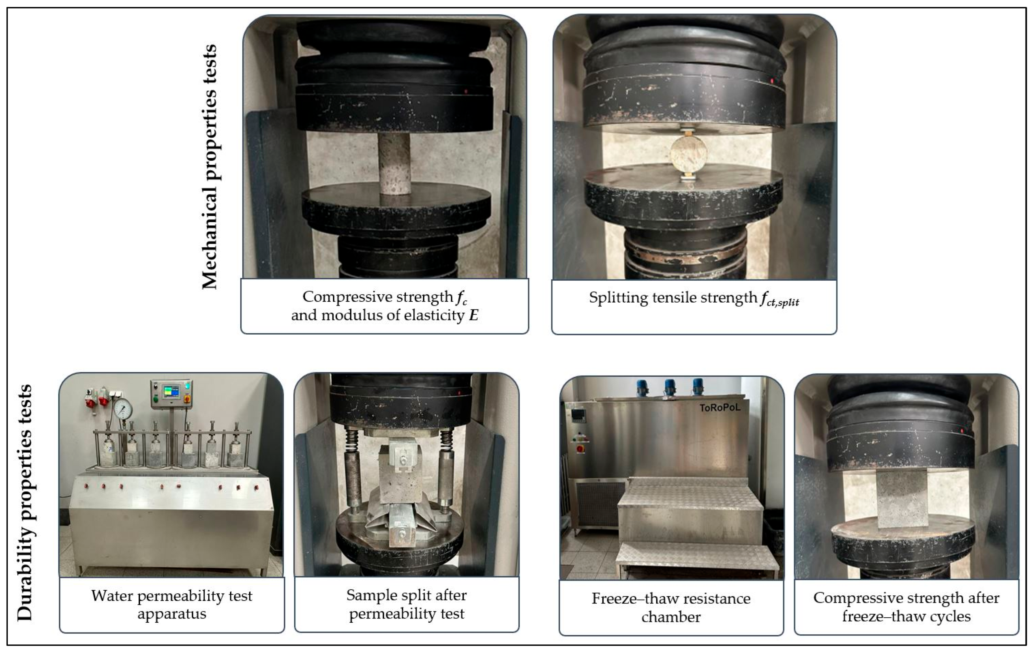
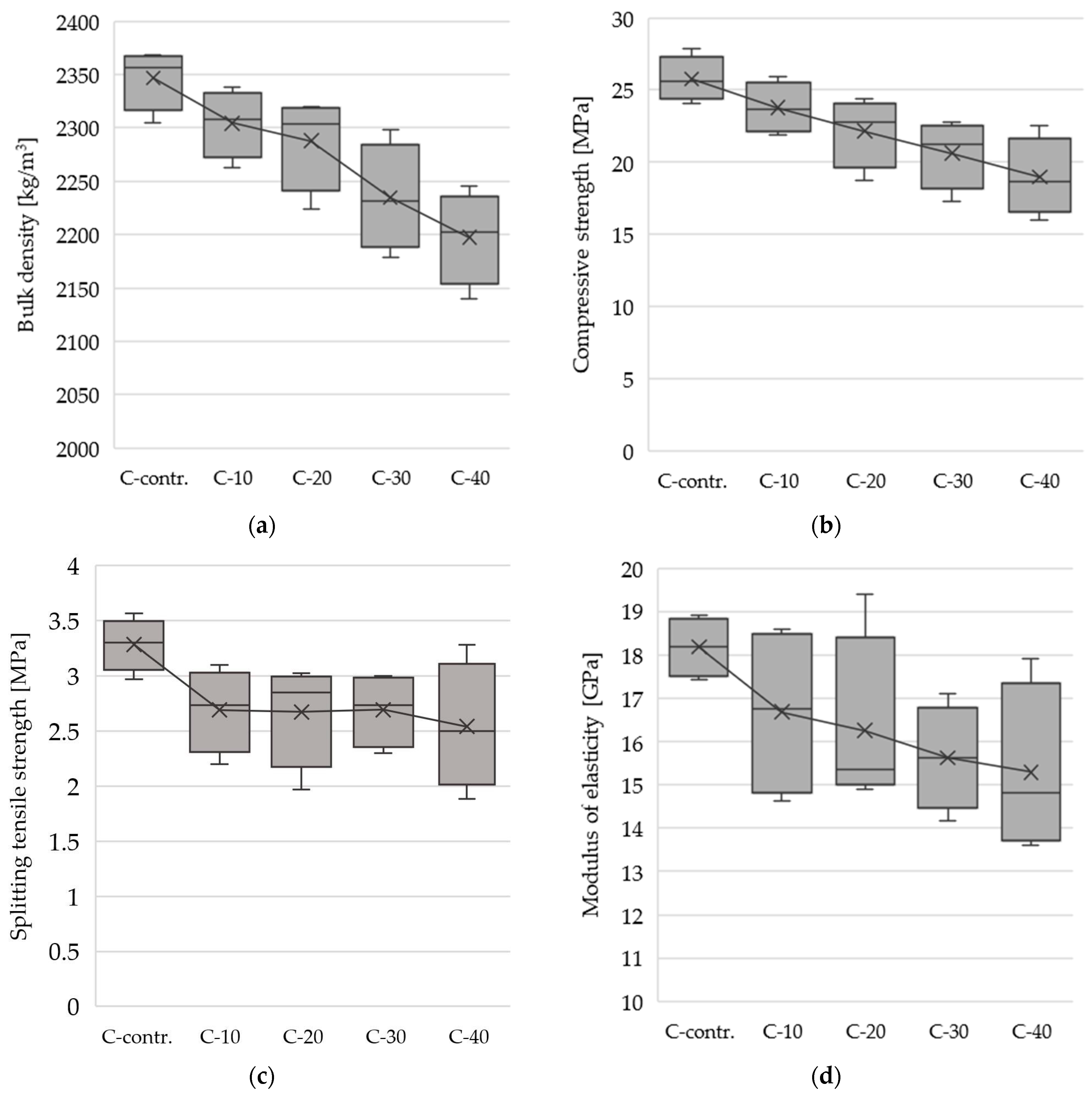
The results of the volumetric density, uniaxial compression, and tensile strength and compressive modulus tests are presented in
Figure 4 as box-and-whisker plots. The box represents the range from the first to the third quartile (i.e., the range covering the middle 50% of all results), the horizontal line indicates the median, and the symbol “×” marks the arithmetic mean of the results. The whiskers include the minimum and maximum results with the exception of outliers, which are presented individually (no outliers were identified for the studies analysed). The results obtained show that the presence of GFRP fibres in the concrete affected all the physical and mechanical properties tested. With increasing GFRP fibre content, all measured parameters decreased, and a noticeable increase in the scatter of results was observed. As the percentage of recycled GFRP in the fine aggregate increased, the volumetric density of the concrete decreased; each 1% increase in GFRP content corresponds to an average decrease in concrete density of approximately 3.7 kg/m
3.
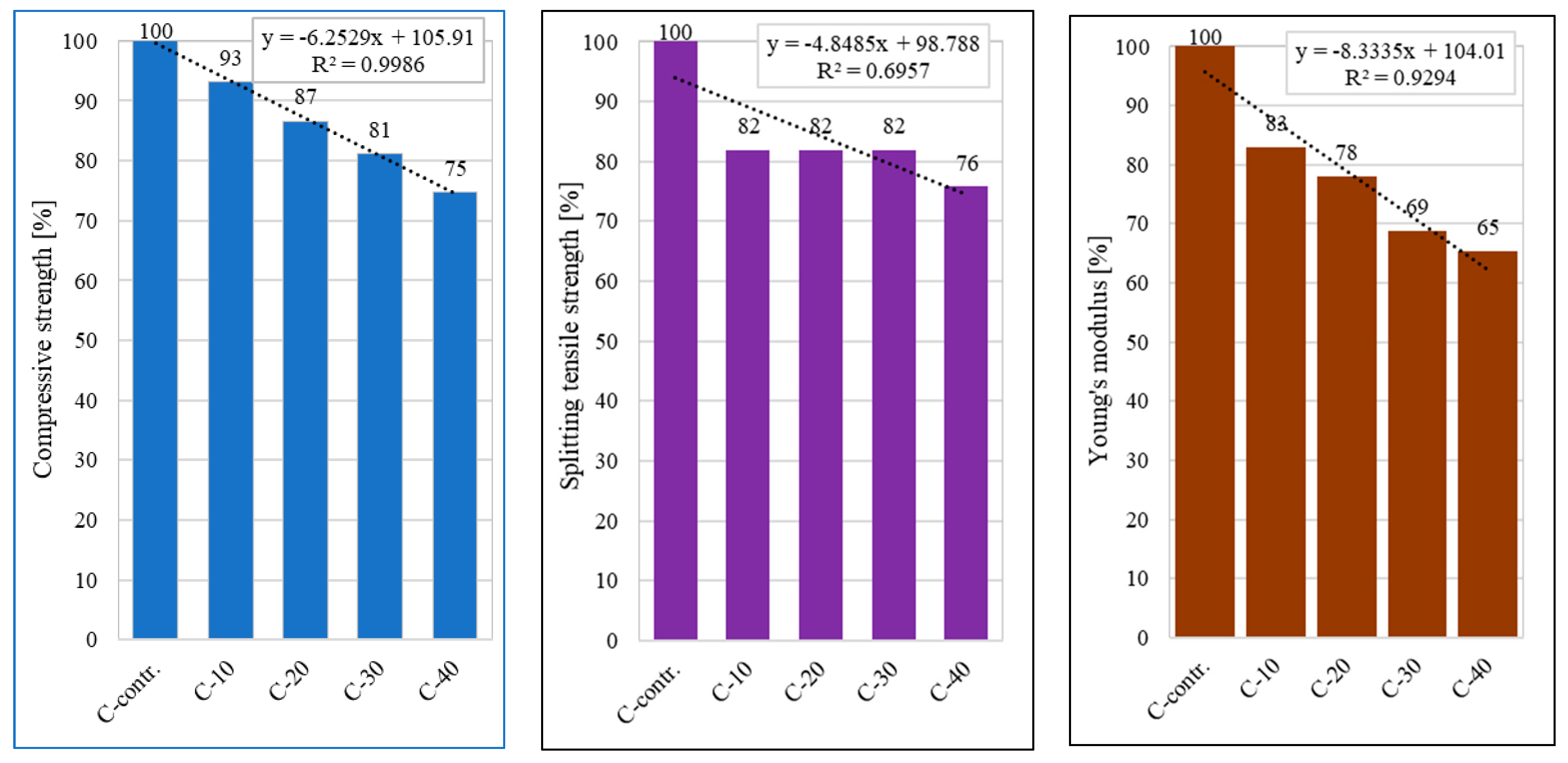
Analysis of the compressive strength (cylindrical samples ∅50 mm × 100 mm) results showed a significant effect of using ground GFRP fibres as an aggregate substitute on the mechanical properties of the concretes. The highest compressive strength value was obtained for the reference sample C-contr. (25.6 MPa). The addition of 10% fibres (sample C-10) resulted in a slight decrease in strength to a value of 23.9 MPa, which was a decrease of 7% compared to the control sample. As the fibre content increased, a further systematic decrease in compressive strength was observed. The sample containing 20% GFRP fibres (C-20) reached a value of 22.2 MPa, a decrease of about 13% relative to the control sample. For sample C-30 (30% GFRP fibres), a strength of 20.8 MPa was recorded, 19% less than the reference sample. The lowest strength value (19.2 MPa) was obtained for sample C-40 with the highest (40%) fibre content, which corresponded to a decrease of as much as 25% relative to the control sample.
The effect of the addition of GFRP fibres on the splitting tensile strength of the concretes was also observed. The C-contr. reference sample had the highest average tensile strength value of 3.3 MPa. The use of GFRP fibres as a replacement for aggregate resulted in lower average tensile strength values for all tested samples compared to the control sample. For samples containing 10%, 20%, and 30% GFRP fibres (samples C-10, C-20, C-30), identical average values of 2.7 MPa were recorded, a decrease of 18% from the reference sample. In contrast, the highest decrease in average strength (2.5 MPa, 24%) was obtained for the sample with the highest fibre content (C-40).
Tests of the modulus of elasticity (cylindrical specimens Ø50 mm × 100 mm) showed a significant effect of ground GFRP fibre content on this property. The highest average value of the modulus of elasticity was obtained for the reference sample (C-contr.), at 18.2 GPa. Replacement of part of the aggregate fraction 2–8 mm with GFRP fibres resulted in a significant reduction in the average modulus of elasticity values as the amount of fibres increased. At 10% fibre addition (C-10), the average modulus value decreased to 16.8 GPa, a reduction of 17% compared to the control sample. Increasing the amount of fibres to 20% (C-20) resulted in a further reduction in modulus to 16.4 GPa, a decrease of 22% relative to the reference sample. At a fibre content of 30% (C-30), the average value of the modulus was 15.6 GPa, corresponding to a decrease of 31%. The lowest average value of 15.3 GPa (a decrease of 35%) was recorded for the sample containing the highest fibre content tested, i.e., 40% (C-40).
3.2. Structural Testing
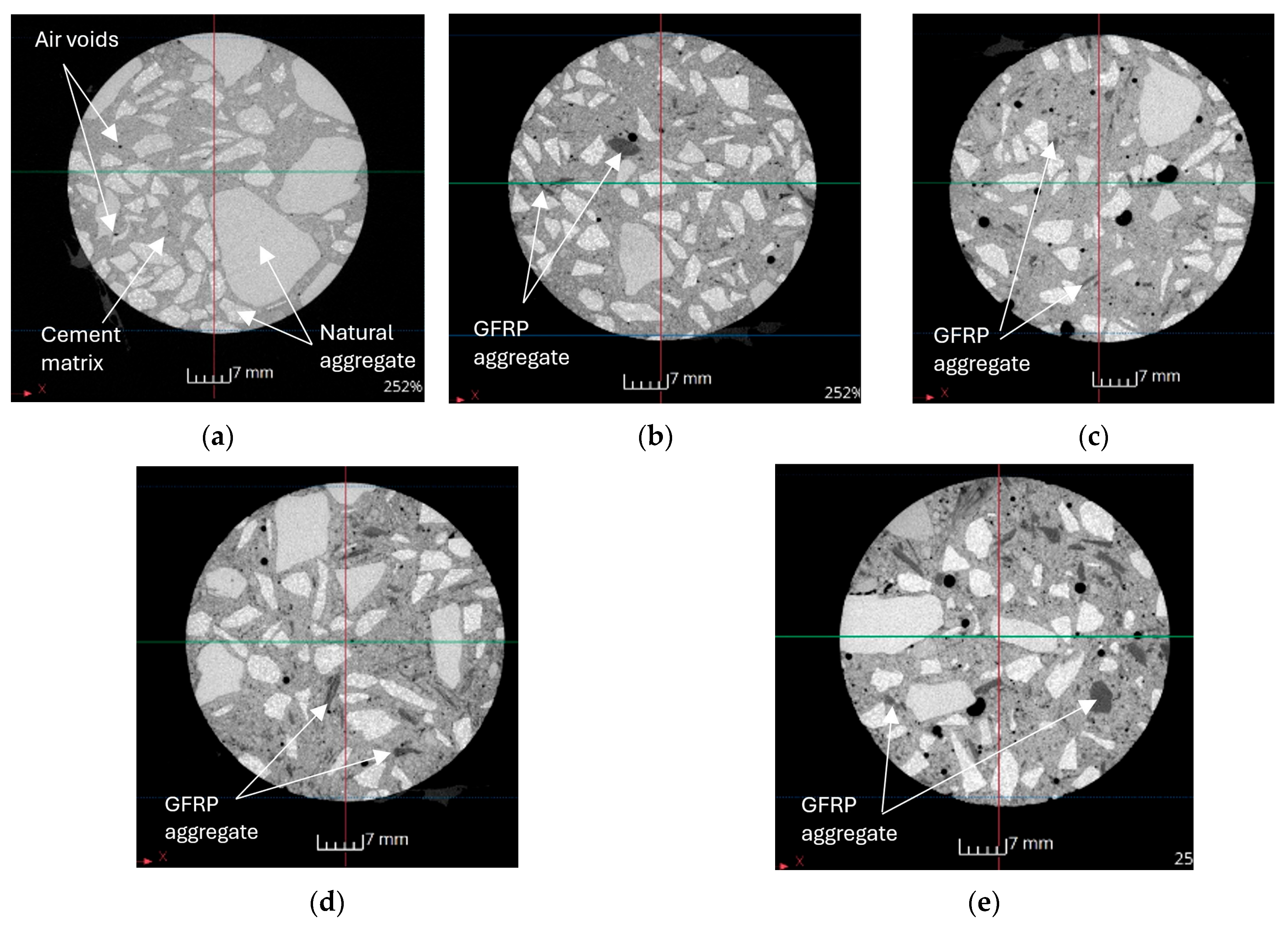
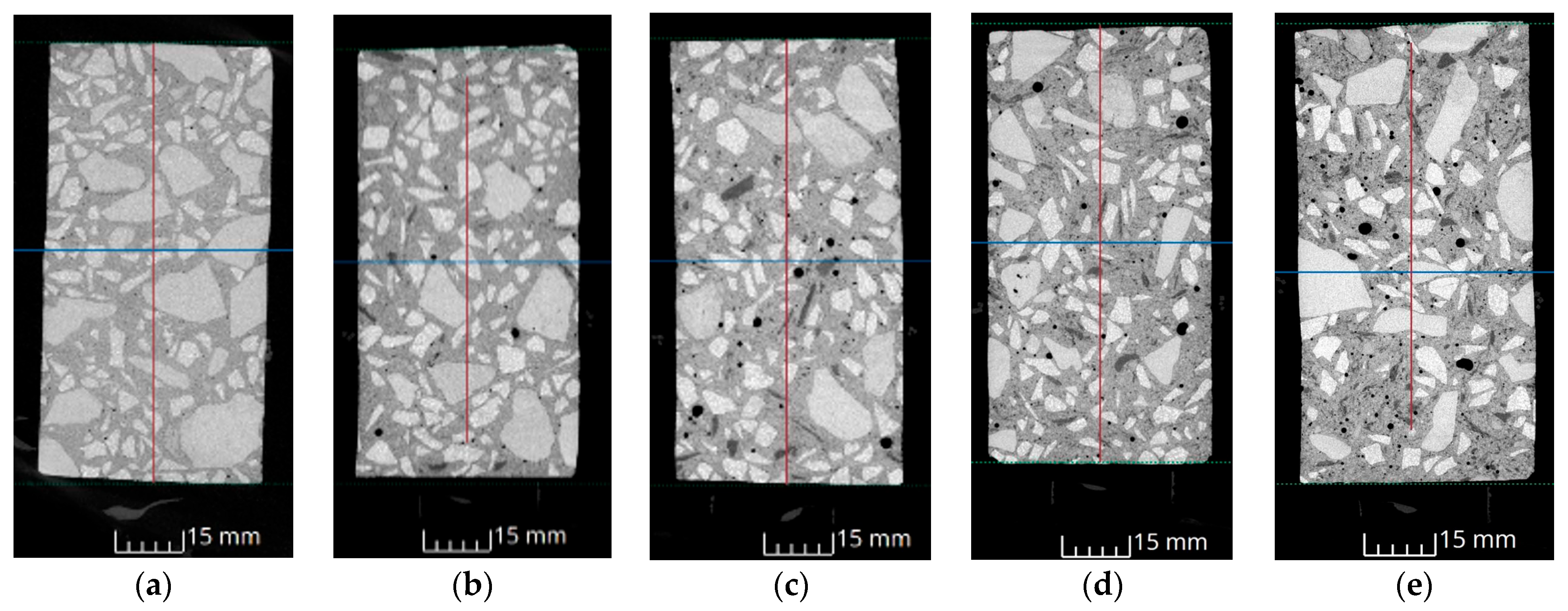
X-ray CT tests provided insight into the distribution of GFRP fibres in concrete samples.
Figure 5 and
Figure 6 show cross-sectional and longitudinal CT images in which GFRP fibres can be unambiguously identified. Analysis of the structure images of the concrete samples identified as C-contr., C-10, C-20, C-30 and C-40, showed noticeable changes in the microstructure due to the increasing content of fragmented GFRP fibres. The C-contr. reference sample was characterised by a compact and homogeneous structure (
Figure 5a and
Figure 6a), with no visible defects, pores, or other significant internal disorders.
The cement matrix, together with the aggregate grains, formed a cohesive and homogeneous composite. In the case of sample C-10, which contained 10% GFRP fibres, the first signs of a change in structure were observed, consisting of the presence of individual, small areas of local defects and pores, indicating the difficulty in achieving perfect mixing of the concrete mixture components (
Figure 5b and
Figure 6b). A further increase in fibre content to 20% (sample C-20) resulted in an increase in microstructural heterogeneity and a more pronounced appearance of pores (
Figure 5c and
Figure 6c). This was probably due to weaker interaction between the GFRP fibres and the cement matrix. The structure of sample C-30, containing 30% GFRP fibres, was already clearly porous and much less homogeneous (
Figure 5d and
Figure 6d). An uneven distribution of fibres in the matrix was observed, which further reduced the cohesion of the structure. The most unfavourable changes were observed for sample C-40, with the largest number of fibres (
Figure 5e and
Figure 6e). Its microstructure was characterised by intense porosity and significant inhomogeneities. There was a clear reduction in the effectiveness of the bond between the fibres and the cement matrix, which was reflected in reduced mechanical parameters.
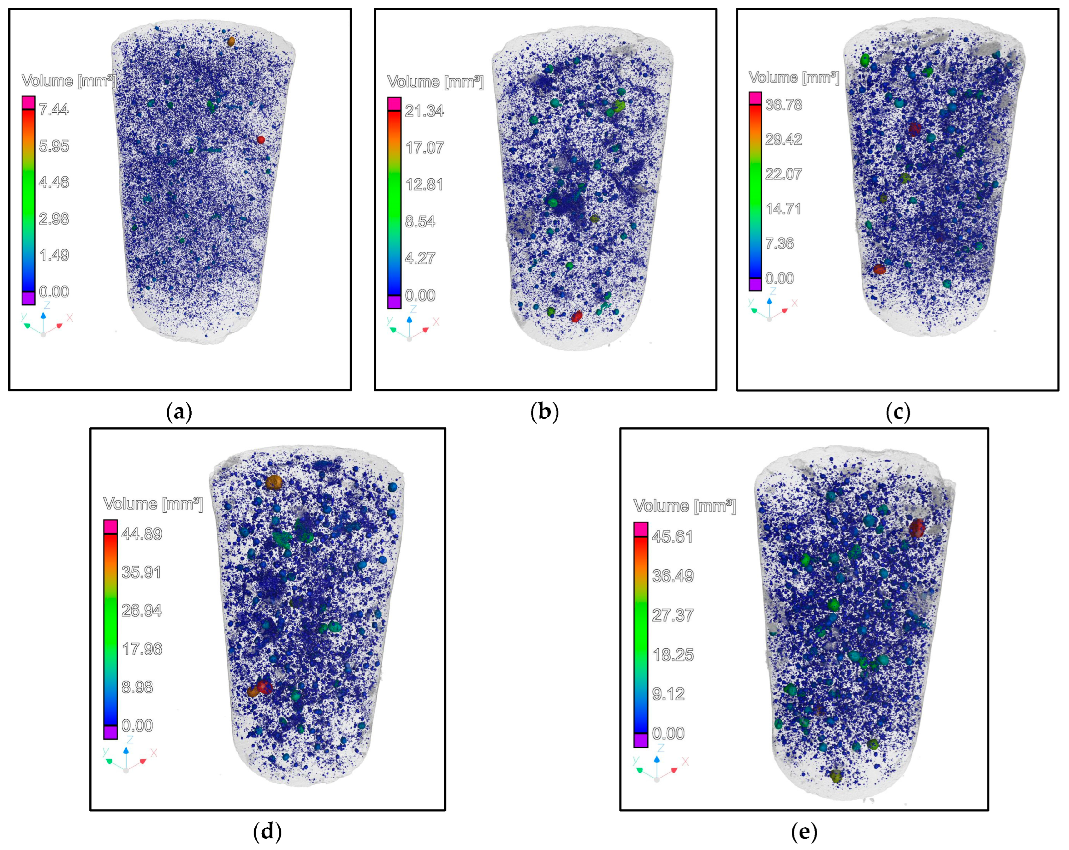
X-ray CT analysis provided additional insight into the pore structure of the concretes with varying GFRP contents. The scans revealed that overall porosity increased slightly with higher replacement levels, ranging from 4.41% in the control mix to 5.33% at 40% GFRP (
Table 4). More importantly, the distribution of voids shifted: in the reference sample, pores were small and relatively uniform, whereas in the high-GFRP mixes, larger, irregular air voids were detected. These observations are consistent with the microstructural heterogeneity expected when incorporating shredded composites and help explain the reduced mechanical and durability performance observed at higher replacement ratios. The results of the analysis in the form of 3D graphics are shown in
Figure 7.
3.3. Waterproofing Tests
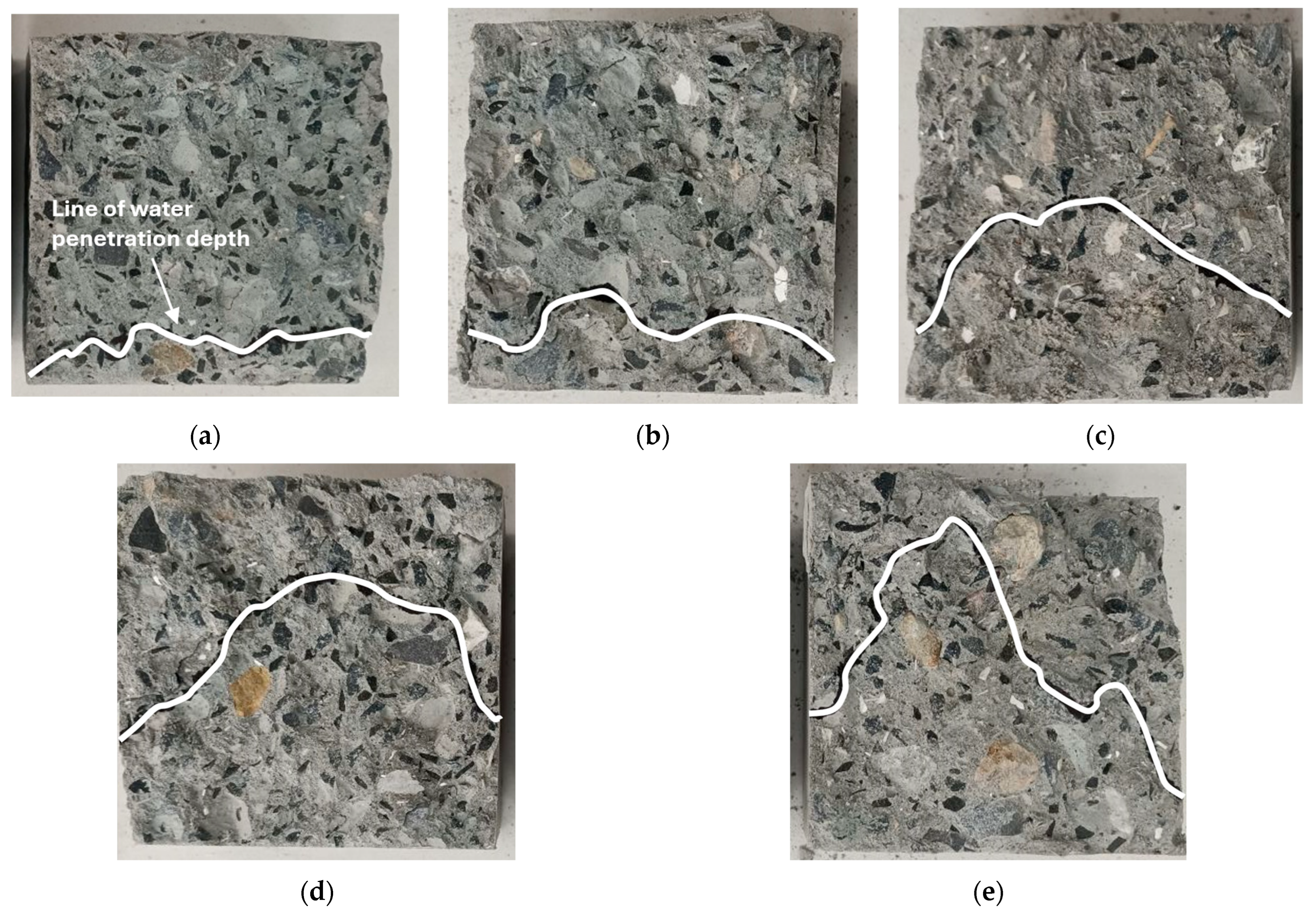
All of the samples withstood the watertightness test, maintaining a water pressure of 1.2 MPa over the test period, corresponding to watertightness class W12. However, fracture analysis of the specimens after testing showed clear differences in water migration resistance depending on the GFRP fibre content. Examples of the obtained fracture images of the samples after the test are shown in
Figure 8. Analysis of the fractures indicated that the reference sample had the smallest extent of water penetration (
Figure 8a). The structure of this sample was homogeneous, compact, and without any clear pores or defects, which was favourable for limiting water migration. For the sample with the addition of 10% GFRP fibres, a slight increase in the extent of water penetration was observed compared to the reference sample (
Figure 8b). Local zones of water migration were evident, which corresponded to previous observations of slight porosity in the structure when analysing the structural images. Sample C-20 (
Figure 8c) showed a further deterioration of the resistance to water penetration, with a greater extent of migration. This situation corresponded to the structural images, which indicated more developed porosity and heterogeneity in the microstructure. Gradually, even more pronounced water migration was observed in samples containing 30% and 40% GFRP fibres where the height of water penetration was clearly higher (
Figure 8d,e).
3.4. Frost-Resistance Tests
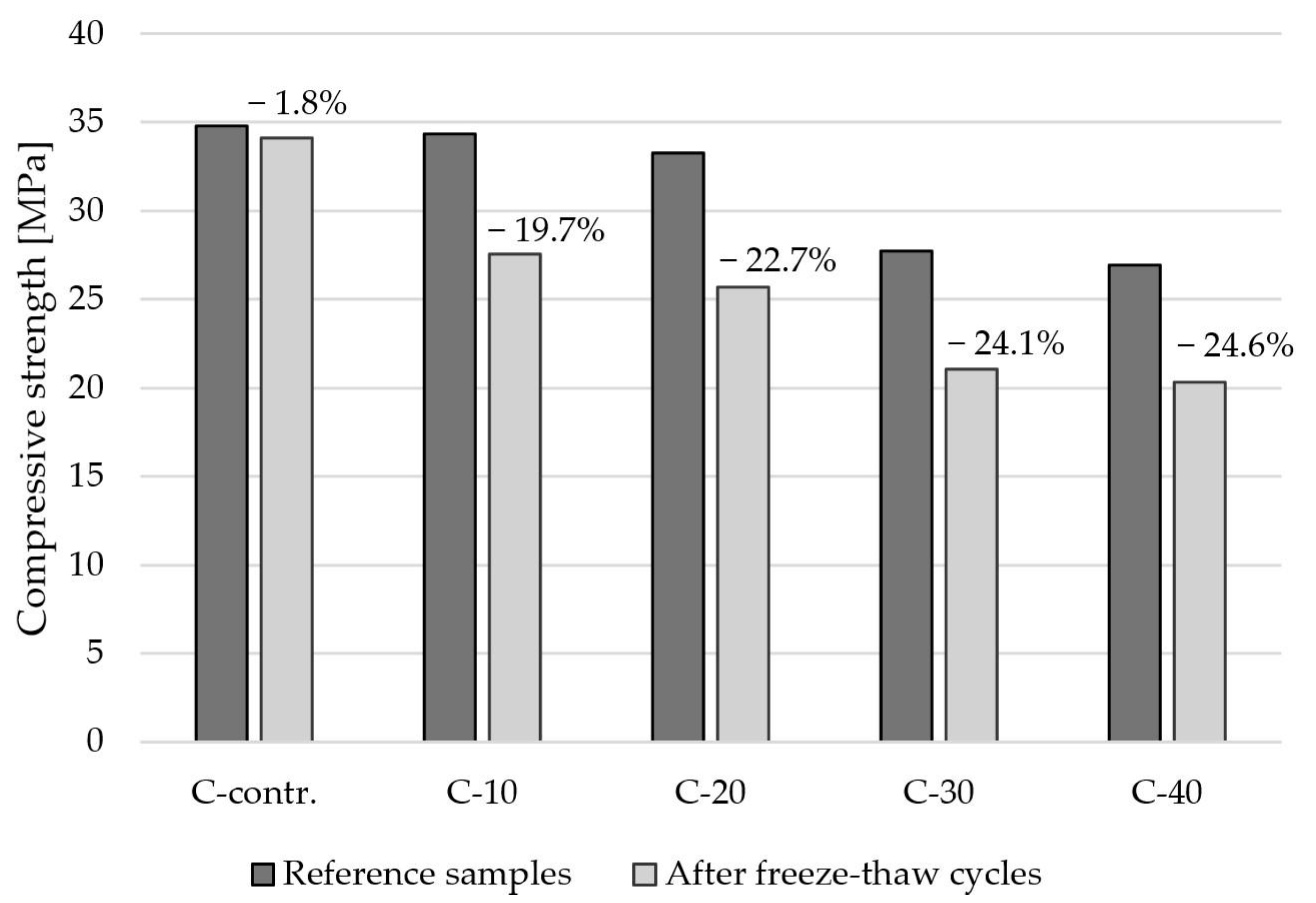
Figure 9 shows a comparison of the compressive strength results of concrete specimens (cubic specimens 100 × 100 × 100 mm) for a series subjected to 50 cycles of freezing and thawing and for a reference series (specimens stored in water at approximately 20 °C).
Analysis of the frost-resistance tests (50 freeze–thaw cycles) showed a clear influence of GFRP fibre content on the compressive strength of concrete. The reference series (C-contr.) reached an average compressive strength of 34.8 MPa; for the series without fibre addition, only a slight decrease in this value to 34.1 MPa was observed after 50 cycles. The series of reference specimens with the addition of GFRP fibres showed a reduction in strength compared to the reference series of C-contr. For the reference series with fibres, the following compressive strength values were recorded: for 10% fibres (C-10)—34.3 MPa, 20% fibres (C-20)—33.2 MPa, 30% fibres (C-30)—27.7 MPa and 40% fibres (C-40)—26.9 MPa. For the tests after 50 freeze–thaw cycles, all series of fibre-added specimens recorded significant decreases in compressive strength. The strengths were, respectively, 27.6 MPa (C-10M), 25.7 MPa (C-20M), 21.0 MPa (C-30M), and 20.3 MPa (C-40M). According to the PN-88/B-06250 standard, the frost-resistance class is designated by the symbol F and the number corresponding to the number of freeze–thaw cycles to which the samples were subjected during the test, while maintaining the required (no more than 20%) decrease in strength. Concrete without added fibres (C-contr.) and with the addition of 10% GFRP fibres achieved a frost-resistance class F50; the other concretes with 20–40% content do not meet the requirements and thus do not obtain the frost-resistance class according to the PN-88/B-06250 standard.
4. Discussion
GFRP is relatively lightweight, and, compared with natural aggregates, its density is about 30–35% lower. As a result, its use as a replacement leads to a reduction in the density of both fresh and hardened concrete. The density of hardened concrete decreased from 1.8% (C-10) to 6.4% (C-40) compared with the control sample. Results reported in the literature also indicate a change of a few percent in density, which can be beneficial if the weight of building structures needs to be reduced. Asokan et al. showed that the use of pulverised waste GFRP with a content of 5 to 50% over fine aggregate reduced the density of the hardened mix by 1 to 11% [
20]. In contrast, a reduction in the density of fresh concrete from 1.7 to 5.8% when GFRP powder was used at 5, 10, 15, and 20% as a substitute for fine aggregate was demonstrated by Correia et al. [
25]. In addition, the presence of GFRP in concrete causes difficulties in compacting the mixtures, resulting in lower densities as the proportion of GFRP increases. As shown in a study presented by Dehghan et al., mortars with 5% wt. GFRP replacement of the aggregate reduced the density of the fresh mix from 2244 kg/m
3 (control sample) to 2109–2192 kg/m
3. Recycled GFRP increased the air content from 2.3% (control) to 4.4–9.2%, and recycled GFRP additions also decreased the flowability of the mixtures [
21]. The structural analysis carried out clearly showed that, with the increase in GFRP fibre content in the concrete samples, there was a gradual deterioration in the homogeneity and cohesion of the structure of the concretes, which directly correlated with the obtained results of the strength, water permeability, and porosity tests.
The results of uniaxial compressive strength tests indicate that the strength of the concretes decreased as the proportion of GFRP fibres in the concretes increased. The addition of 10% fibres (sample C-10) resulted in a slight decrease in strength by 7% compared with the control sample. For sample C-20, the strength decreased by 13%. Samples in which the proportion of GFRP fibres was 30% and 40% had lower compressive strength by 19% and 25%, respectively (
Figure 10). The observed decrease in compressive strength may be due to the deterioration of the homogeneity of the concrete structure with an increase in GFRP fibre content, as well as the weaker mechanical characteristics of the fibres themselves compared to natural aggregate. These results suggest that there is a certain limiting fibre content above which the decrease in mechanical performance becomes very pronounced. Literature data also report changes in the mechanical parameters of mortars and concretes with recycled GFRP. Mortars in which sand was replaced by GFRP at 1% by volume showed virtually the same compressive strength as the control mix, while replacements of 3% and 5% by volume resulted in a reduction of approximately 4–12% compared to the control [
26]. In another study, concrete mixtures with GFRP fibres at 1% and 1.75% by volume of sand [
17] exhibited only a slight decrease in compressive strength—by about 1% and 4%, respectively—while flexural strength increased to 106% and 115% of the control value. On the other hand, replacing coarse aggregates (16 and 20 mm) with GFRP aggregates at 33%, 66% and 100% by volume significantly affected the properties of the concretes. Compressive strength decreased to 68, 53, and 38% of the strength of the control sample, respectively, while flexural strength decreased to 69, 58, and 43% of the strength of the control sample, respectively. Such a significant decrease in the strength of concrete mixtures containing GFRP aggregates was attributed to their lower strength, the presence of wood impurities and the smooth surfaces of GFRP aggregates [
17]. Removing wood from crushed GFRP improved the results: for concrete with 33% GFRP aggregates, the reductions in compressive and flexural strength were limited to 80% and 81% of the control strength. Rodin et al. also studied the effect of fibre size on the mechanical parameters of mortars. Large fibres (greater than 2 mm) resulted in an increase in compressive strength of up to 2%. In contrast, the use of smaller-sized fibres resulted in a 26–41% decrease in strength compared to the control mortar [
26]. In general, the smaller the fibre size, the greater the decrease in strength. This was due to the fact that as the surface area of the GFRP increases, a higher binder content is required to allow the fibres to bind completely in the cement matrix. In addition, the decrease in strength was attributed to the increased difficulty in achieving proper compaction at higher volume percentages of GFRP. Flexural strength tests after 7 days of mortar seasoning were no longer as conclusive.
Using GFRP fibres instead of aggregate decreased the average splitting tensile strength of all the samples tested compared to the control sample. For samples containing 10%, 20%, and 30% GFRP fibres (samples C-10, C-20, C-30), there was an 18% decrease in strength relative to the reference sample. In turn, a decrease in average strength to a value of 2.5 MPa, that is, by about 24% was obtained for the sample with the highest fibre content, 40% (C-40). The results obtained suggest that moderate amounts of GFRP fibres (10–30%) cause a similar effect on the decrease in splitting tensile strength, while a higher fibre content (40%) leads to further deterioration of properties. This may be due to the limited ability of the concrete–fibre composite to effectively transfer tensile stresses at higher GFRP fibre contents. In addition, the size and shape of the recycled GFRP also affects the mechanical performance of mortars and concretes. The results in [
19] showed that the presence of fibre-reinforced polymer bar in concrete causes a reduction in the average compressive strength of concrete and the average splitting tensile strength of concrete. This was indicated to be due to better bonding between mortar and natural aggregates than between mortar and waste. Natural aggregate particles have irregular shapes and rough surfaces, so they maintain a good physical bond with mortar in concrete. Strands protruding from the prism’s fracture faces which helped bridge cracks during testing were noted while performing flexural strength tests [
26]. The recycled GFRPs used in the study are mainly longitudinal in form, while the presence of fine flake-shaped particles is noticeable, which may not have the same bonding effect as longitudinal fibres when tensile forces are applied.
The results of concrete modulus tests indicate that increasing the amount of GFRP fibres results in a marked reduction in the stiffness of concrete from 17% (C-10) to 35% (C-40) compared to the control sample. This is likely due to the lower stiffness of the GFRP fibres themselves compared to natural aggregate, as well as changes in the microstructure of the concrete. The observed trend indicates that there is a clear limit to the optimal fibre content at which the material’s mechanical properties would be preserved, while achieving the intended performance goals. The waterproofing results also correlate directly with the significant porosity and significant structural inhomogeneities observed during microstructure analyses. Although all tested concretes achieved the W12 watertightness rating, the mix with the highest GFRP content (40% replacement) exhibited a noticeably greater water penetration depth compared to the control and lower-addition mixes. This behaviour can be explained by the more heterogeneous and porous microstructure observed in X-ray CT images of high-GFRP concretes, where weak fibre–matrix bonding and uneven fibre distribution promoted the formation of interconnected voids. These voids and microcracks act as preferential capillary pathways, enabling faster water ingress under pressure even when the bulk matrix remains intact. In practical terms, this indicates that while the material can still withstand the applied pressure threshold required for W12 classification, higher GFRP contents may reduce the margin of safety against local permeability increases, potentially affecting long-term durability under cyclic wetting or exposure to aggressive agents. In turn, frost-resistance tests indicate that the addition of shredded GFRP fibres at 10% provides acceptable resistance to freeze–thaw cycles (19.7% reduction in strength). Higher fibre content (30–40%) leads to a significant reduction in the frost life of concrete (above 24%), which may limit the use of such mixtures in environmental conditions exposed to frost. Similar relationships were presented by Masmoudi et al. [
27]. The frost resistance of concrete containing fibreglass from wind turbine blades, replacing both lightweight and coarse aggregates at 50% and 100% levels, was investigated. The experimental results showed that the compressive strength of all samples exposed to 200 freeze/thaw cycles was lower than that of the reference samples from the same mixtures stored under standard conditions.
From an economic perspective, the raw material cost of recycled GFRP from decommissioned wind turbine blades is minimal; however, the processing operations required to obtain a consistent particle fraction—cutting, shredding, cleaning, and sieving—introduce additional expenses compared with the use of natural aggregates. The competitiveness of GFRP as an aggregate substitute therefore depends strongly on processing efficiency and the availability of local waste streams. Environmentally, replacing part of the natural aggregate with GFRP can reduce the demand for quarrying and associated CO2 emissions, while simultaneously avoiding the disposal of composite waste to landfills. A full life-cycle assessment and cost–benefit analysis would be necessary to quantify these advantages and define scenarios where GFRP substitution is both economically and environmentally optimal.
5. Conclusions
The article examined the potential for recovering shredded glass fibre-reinforced polymer (GFRP) composites from deconstructed wind turbine blades. This waste was used as a substitute for 2–8 mm aggregate in concrete at replacement levels of 10%, 20%, 30%, and 40% by volume. The main conclusions are as follows:
- -
The distribution of GFRP fibres in the cement matrix was irregular, which reduced structural homogeneity and increased porosity.
- -
Increased porosity and the lower density of GFRP fibres compared with natural aggregates led to a reduction in concrete density with increasing fibre content.
- -
Replacing natural aggregate with GFRP fibres reduced the performance of hardened concrete, including compressive strength, splitting tensile strength, modulus of elasticity, water resistance, and frost resistance.
- -
Structural changes observed in non-destructive testing (X-ray CT) were consistent with the mechanical and durability test results under water exposure and low-temperature conditions.
Recovering fibres from wind turbine blades offers new possibilities for waste management and the production of environmentally friendly building materials (green building materials). The results do not disqualify the possibility of using GFRP waste to produce concrete mixtures. Despite the clear impact of this type of waste on the properties of concretes, it is possible to develop a mix that can be practically used, for example, for the production of prefabricated elements.
Future research should investigate ways to counteract the loss of mechanical performance. Possible strategies include adjusting the particle size distribution to improve packing; applying surface treatments (e.g., silane coupling agents, alkaline washing) to increase fibre–matrix adhesion; and combining mechanical processing with mild chemical or thermal treatments. It may also be worth studying hybrid approaches, where GFRP is blended with other recycled fillers, to balance sustainability with performance.
