Article

Sustainable Indoor Thermal Regulation with Hybrid Desiccant and Post-Cooling Technologies

by
Lolaksha Shettigar
1,
Nitesh Kumar
1,
Madhwesh Nagaraj
1,
Mandya Channegowda Gowrishankar
1,
Shiva Kumar
1,* and
Sampath Suranjan Salins
2
1
Department of Mechanical and Industrial Engineering, Manipal Institute of Technology, Manipal Academy of Higher Education, Manipal 576104, India
2
Department of Mechanical Engineering, School of Engineering and Information Technology, Manipal Academy of Higher Education, Dubai 345050, United Arab Emirates
*
Author to whom correspondence should be addressed.
Sustainability 2025, 17(17), 7805; https://doi.org/10.3390/su17177805
Submission received: 3 June 2025 / Revised: 6 August 2025 / Accepted: 11 August 2025 / Published: 29 August 2025

Abstract

This study investigated the performance of a hybrid desiccant dehumidification system integrated with a post-cooling mechanism, focusing on its application to energy-efficient indoor climate control. A liquid desiccant system using magnesium chloride (MgCl2) was tested in its pure form and in combination with silica gel at 10% and 20% concentrations to enhance its moisture removal capabilities. The key parameters, including the air velocity (3–6 m/s), desiccant flow rate (1–3 LPM), and desiccant composition, were varied to analyze their effects on the dehumidification efficiency, moisture removal rate (MRR), temperature reduction after post-cooling, and coefficient of performance (COP). The results show that post-cooling using a crossflow heat exchanger effectively lowered the exit air temperature, ensuring thermal comfort. Addition of silica gel significantly improved system performance. The MgCl2 + 20% silica gel mixture achieved the highest dehumidification efficiency of 0.86, the greatest temperature drop of 1.95 °C, and the maximum COP of 2.36 at optimal flow conditions. While the dehumidification efficiency declined with increasing air velocity due to reduced contact time, the COP increased owing to the higher thermal processing of the air stream. This study highlights the potential of optimized hybrid desiccant systems as sustainable solutions for building air conditioning, aligning with the key Sustainable Development Goals (SDGs) related to clean energy, climate action, and sustainable infrastructure.

1. Introduction

The global demand for energy-efficient and environmentally sustainable cooling solutions has significantly driven research into alternative air conditioning technologies. Liquid desiccants have emerged as a transformative technology due to their unique ability to independently manage latent and sensible heat loads, particularly in hot and humid climates. Unlike traditional vapor compression systems, liquid desiccant-based air conditioning systems separate temperature control from humidity regulation, thereby improving energy efficiency and operational flexibility.
Recent advancements in liquid desiccant cooling systems (LDCSs) have been explored across multiple research directions. To improve the coherence and narrative flow, the current literature is reviewed under three broad themes: the integration of LDCSs with solar-assisted or hybrid energy systems, design innovations and a performance analysis of desiccant dehumidifiers, and the use of composite desiccants. Among the most commonly studied liquid desiccants are lithium chloride (LiCl), calcium chloride (CaCl2), and magnesium chloride (MgCl2). Previous studies have explored the capabilities and improvements in liquid desiccant systems over the years. Fekadu and Subudhi [1] emphasized the role of renewable energy in powering liquid desiccant cooling systems (LDCSs), showcasing their potential to reduce reliance on fossil fuels. Their analysis underscored the compatibility of LDCSs (liquid desiccant cooling systems) with solar-assisted systems and identified the critical challenges, such as corrosiveness and carryover, which may hinder operational efficiency. Rafique et al. [2] explored material innovations in HVAC applications, highlighting that while LiCl offers excellent stability and moisture absorption properties, its high cost can be mitigated by blending it with CaCl2. The authors further discussed the technological advancements, like rotary liquid dehumidifiers and multistage membrane systems, which address issues of droplet carryover and pressure drops, thus enhancing system performance. Shukla and Modi [3] explored the economic and operational viability of solar-powered LDCSs, concluding that their reduced operational cost makes them a competitive alternative to conventional systems. Their findings emphasized a hybrid solar system’s ability to optimize energy savings and provide solutions for building cooling requirements and portable water production. Jain and Bansal [4] examined the effectiveness of hybrid configurations, revealing that internally cooled systems achieved maximum dehumidification effectiveness under specific operating conditions. Similarly, Liu et al. [5] validated the superior mass transfer efficiency of counter-flow configurations over parallel and crossflow designs, offering valuable insights into optimizing dehumidifier design. Gandhidasan [6] introduced a simplified model for air dehumidification, validated through experimental data. Their study emphasized the importance of low cooling water inlet temperatures and an efficient heat exchanger design for improving desiccant performance. Liu et al. [7] and Mohammada et al. [8] compared LiBr and LiCl solutions, identifying LiCl as a cost-effective option with excellent dehumidification properties. Further research conducted by Sharma and Kaushal [9] explored multi-channel flat-plate liquid desiccant systems, noting that these designs achieved enhanced dehumidification with a moisture absorption rate of 5.21 g/kg at optimal operating conditions. Yin et al. [10] validated these findings, emphasizing the need for innovative designs to minimize desiccant carryover and to optimize airside pressure drops. Bai et al. [11] discussed the potential of ionic liquids as desiccants, noting their non-volatility and high thermal stability. These materials can be tailored to specific applications but require further research into their economic feasibility and long-term performance. Abdel-Salam et al. [12] highlighted the advantages of membrane-based dehumidifiers, which can minimize droplet carryover and hence could improve mass transfer efficiency. Additionally, Wen et al. [13] introduced a mixed-desiccant novel system incorporating hydroxyethyl urea, achieving a 14.1% improvement in regeneration effectiveness compared to traditional solutions. Pratama et al. [14] conducted a numerical study comparing LiCl and CaCl2 solutions as desiccants. CaCl2 reduced the dehumidification performance by 15% relative to LiCl. Kumar et al. [15] combined membrane-based hydrophobic PVDF in dehumidification systems and found a significant carryover reduction with improved moisture transfer. Fahad et al. [16] presented a comprehensive review of desiccant technologies, highlighting emerging materials and hybrid system integration. Abdelgied et al. [17] reviewed novel desiccant air conditioning systems and outlined the need for control optimization and hybrid energy coupling. Shiva Prasad et al. [18] carried out experimental and ANN-based control optimization on CaCl2 LDCSs under varying operating conditions, achieving robust performance improvements. Despite these advancements, challenges remain in liquid desiccant systems, especially regarding the air temperature after dehumidification. The post-dehumidification air temperature often increases due to latent heat release, as noted by Guan et al. [19], necessitating additional cooling. This might indirectly increase the energy demand. Single desiccants, such as MgCl2 or CaCl2, have problems; for instance, CaCl2 performs poorly under high-temperature conditions, while MgCl2 is prone to crystallization during prolonged use. Material degradation and viscosity changes, highlighted by Lowenstein [20], Riffat et al. [21], and Yin et al. [10], further underscore the need for improved solutions.
One method to improve the performance of desiccants is by mixing two or more desiccants in appropriate proportions to form blends of desiccants. Hybrid desiccants that combine MgCl2 with silica gel have shown promise in overcoming these challenges. Silica gel, known for its high surface area and excellent moisture adsorption properties, enhances MgCl2’s performance by increasing its thermal stability and reducing crystallization risks. Zheng et al. [22] reported significant improvements in moisture absorption and regeneration efficiency with MgCl2–silica gel hybrids. Sharma and Kaushal [9] validated these findings, demonstrating the hybrid’s robust performance under fluctuating environmental conditions.
Despite notable advancements in liquid desiccant systems and hybrid cooling configurations, several key challenges remain. These include limitations in the moisture removal capacity, energy efficiency during regeneration, and the mechanical stability of desiccant materials. The existing studies have either focused on component-level optimization or energy source integration, but limited attention has been given to the combined effect of desiccant composition and airflow channel geometry on system performance. Therefore, a significant research gap exists regarding their experimental analysis; additionally, little attention has been given to integrated post-dehumidification cooling and the long-term durability of hybrid blends.
This research aimed to address these gaps by experimentally evaluating MgCl2–silica gel as a hybrid desiccant for LDCSs. An air-to-water after-cooling arrangement was implemented to cool the dehumidified air exiting the system. Comprehensive studies were conducted by varying the operating conditions and blend percentages to identify the optimal MgCl2–silica gel composition that provides the maximum benefits, potentially compensating for the deficits in traditional cooling technologies.

2. Methodology

2.1. Experimental Test Rig

The present study investigates the performance of MgCl2 as a liquid desiccant, with and without silica gel enhancement, under varying operational conditions.
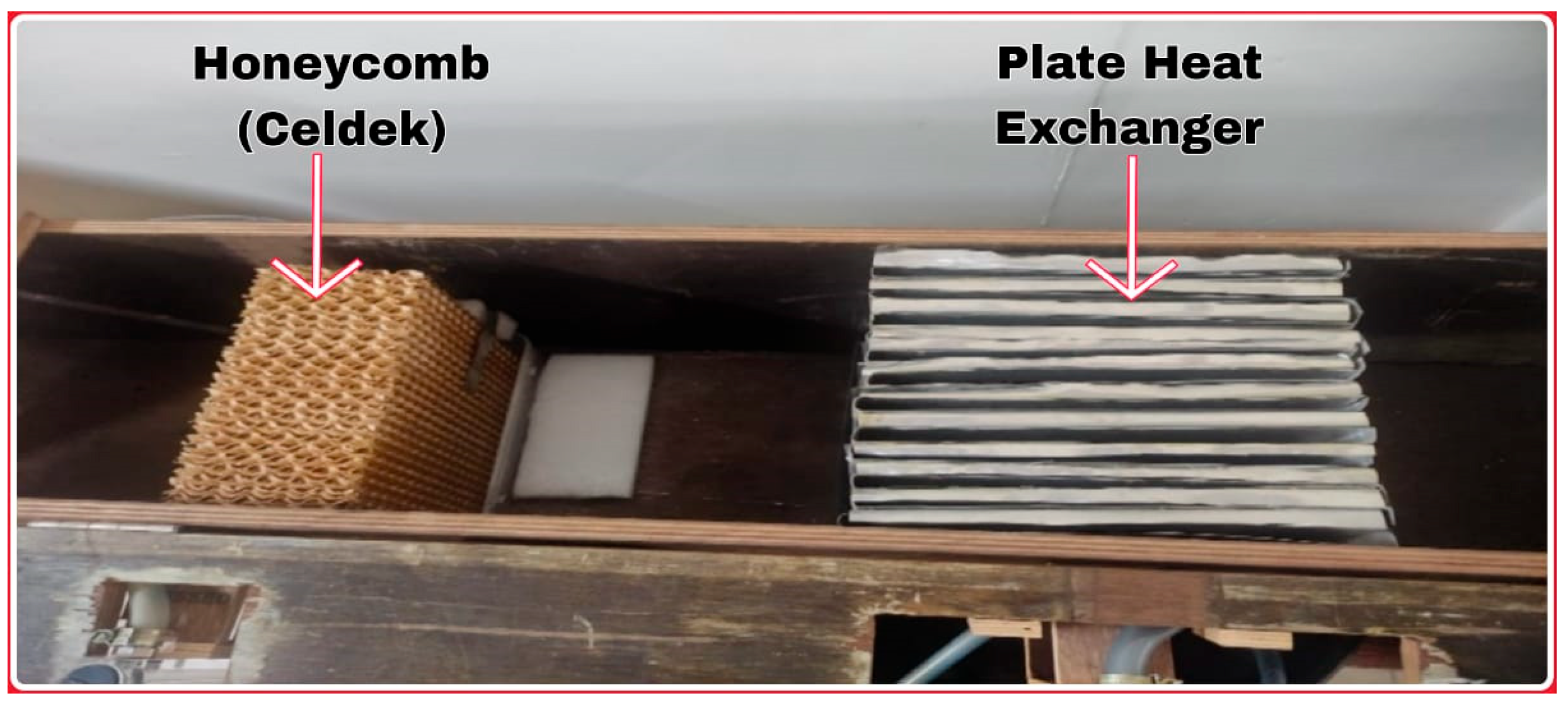
The experimental setup for the liquid desiccant-based air conditioning systems is illustrated in Figure 1. It integrates several key components to analyze the performance of various liquid desiccant configurations. It mainly consists of Air Supply: Hot air is supplied into the system using a blower. The air is directed through a honeycomb structure made of celdek, designed to ensure uniform air distribution and maximize the contact surface with the liquid desiccant. The liquid desiccant (MgCl2 or its hybrid mixtures with silica gel) is stored in the desiccant reservoir. Using a pump, the desiccant is circulated and sprayed uniformly over the honeycomb structure. The desiccant flow rate is monitored and controlled via a rotameter to ensure consistent performance across all the trials. As the hot air flows through the honeycomb structure, it comes into direct contact with the liquid desiccant. The desiccant absorbs moisture from the air, effectively reducing its humidity levels, and due to the dehumidification, the air temperature is increased. The dehumidified air passes through a heat exchanger where it is cooled using a cold-water flow in the crossflow mode. The cooling water is drawn from a reservoir and circulated through the system using a pump. The heat exchanger is constructed using mild steel and configured in a crossflow arrangement, wherein cold water enters from the top and exchanges heat with the air flowing in a perpendicular direction. The flow rate of the cooling water is measured and adjusted using another rotameter. The resulting air, now cold and dehumidified, exits the system. The temperature and humidity of the output air are measured to assess the performance of the desiccant system.
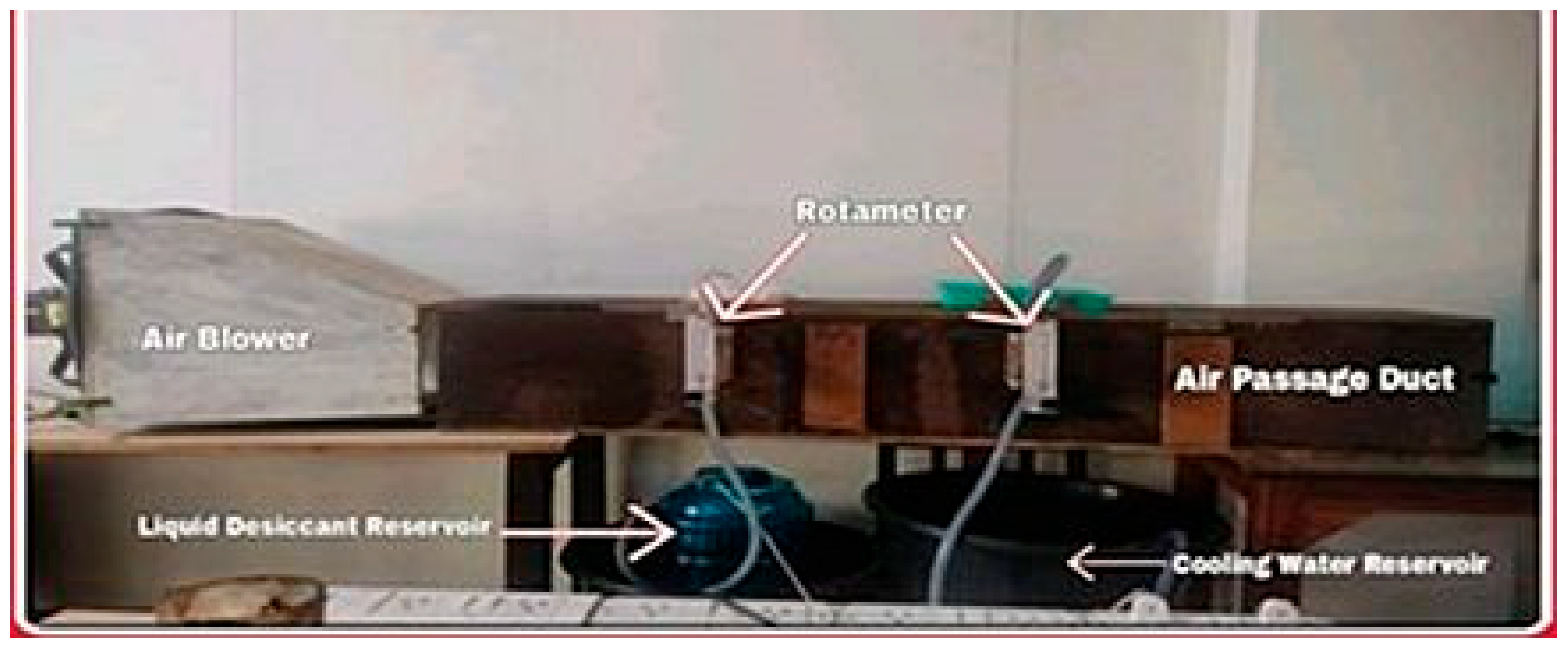
A photograph of the front view of the experimental set up is shown in Figure 2. As illustrated, the blower is positioned on the left side, and a wooden box with a cross-sectional area of 695 cm2 serves as the air passage duct. The rotameter is attached to the wooden box. The liquid desiccant solution is prepared by mixing the crushed desiccant material powder with water in the required proportions, as outlined in Table 1. The desiccant and cooling water reservoirs are located below the wooden box chamber. The honeycomb structure and plate heat exchanger are installed inside the air passage duct, as shown in Figure 3. These visual documents complement the schematic diagram, providing a comprehensive understanding of the experimental arrangement.

2.2. Data Collection

Multiple sensors were installed to record parameters, such as the air temperature, humidity, and flow rates, at each stage of the process. The experimental setup was equipped with various instruments to ensure accurate measurements and a reliable performance evaluation. Hygrometers were used for measuring the relative humidity of the air, K-type thermocouples were used for temperature measurement, anemometers were used for the air velocity, and rotameters were used for the desiccant and cooling water flow rates. Table 1 presents the key specifications of the instruments used in the study. The measuring instruments used and their locations are presented in Table 2. The specifications outlined above ensured the precise control and measurement of the experimental parameters, providing a reliable foundation for evaluating the performance of the hybrid liquid desiccant system.

2.3. Experimental Conditions

The mixture of MgCl2 and silica gel is prepared by mixing the desiccants. To fix the baseline data, experiments are conducted by using clean MgCl2 as the desiccant. The operating conditions, such as the desiccant flow rate, air velocity, and cooling water flow rate, are varied, and both the input and output parameters, such as the temperature and RH, are noted. To evaluate the performance under diverse operational conditions, the following parameters are varied systematically. The experiments are repeated by varying the desiccants, as shown in matrix form in Table 3. The impact of adding silica gel to the MgCl2 desiccant is evaluated by comparing the moisture absorption rate, air dehumidification efficiency, and temperature reduction across the trials with different desiccant configurations. After each trail, the desiccant is regenerated using heat to release the absorbed moisture, ensuring consistent desiccant quality for the subsequent experiments by heating in a hot air oven at 60–65 °C for 45–60 min. Complete drying is verified by checking the desiccant mass stability across 10 min intervals. This ensures consistent desiccant properties before the next run.

2.4. Equations Used

The performance evaluation of the hybrid liquid desiccant system involves various parameters calculated using the following equations. These equations are essential for analyzing the system’s efficiency, moisture removal rate, and thermal performance under different operational conditions.
  • Change in temperature after dehumidification
ΔT1 = T2 − T1
where ΔT1 = change in temperature after dehumidification in °C;
  • T2 = dehumidified air temperature in °C;
  • T1 = entry air temperature in °C.
2.
Change in temperature after post-cooling
ΔT2 = T3 − T1
where ΔT2 = change in temperature after post-cooling in °C;
  • T3 = exit air temperature in °C;
  • T1 = entry air temperature in °C.
Humidity ratio difference
∆ωI = ω1 − ω2
∆ωII = ω2 − ω3
∆ω = ω1 − ω3
where Δω1 = humidity ratio at inlet condition, kg/kg;
  • Δω2 = humidity ratio after dehumidification condition, kg/kg;
  • Δω3 = humidity ratio at outlet condition, kg/kg;
  • ΔωI = humidity ratio difference between inlet and after dehumidification, kg/kg;
  • ΔωII = humidity ratio difference between exit and after dehumidification, kg/kg;
  • Δω = humidity ratio difference between inlet and exit dehumidification, i.e., specific humidity, kg/kg.
3.
Change in enthalpy
Δh = h1 − h3
where Δh = change in enthalpy in kJ/kg;
  • h1 = enthalpy at inlet condition in kJ/kg;
  • h2 = enthalpy at outlet condition in kJ/kg.
4.
Mass of air
m˙air = ρ⋅A⋅V × 3600
where m˙air = mass flow rate of air, kg/h;
  • ρ = air density in kg/m3;
  • A = area of cross section in m3;
  • V = air velocity in m/s.
5.
Mass of water vapor
mv = m˙air × ω
where m˙air = mass flow rate of air in kg/h;
  • ω = humidity ratio at inlet, middle, and exit, in kg/kg;
  • mv = mass of water vapor in kg/h.
6.
Moisture removal rate (MRR)
MRR = m˙air × ∆ω
where m˙air = mass flow rate of air, kg/h;
  • Δω = humidity ratio difference between inlet and exit dehumidification, i.e., specific humidity, kg/kg.
    MRR = moisture removal rate in kg/h
7.
Dehumidification efficiency
η = (∆ω actual)/(∆ω max) × 100
where ∆ω actual = ω1 − ω3 in kg/kg;
  • ∆ω max = ω1 − ωequ in kg/kg;
  • η = efficiency in %;
  • ωequ: Equilibrium specific humidity corresponding to the desiccant’s properties and conditions, in kg/kg.
8.
Coefficient of performance (COP)
COP = de/Ein
where COP = coefficient of performance.
Ein = input energy in KW
de = Desired effect = m˙air × ∆h
where m˙air = mass flow rate of air in kg/s;
  • Δh = change in enthalpy in kJ/kg;
  • de = desired effect in KW.

3. Results and Discussion

By systematically varying the experimental parameters, the study aimed to identify the optimal operating conditions for the hybrid desiccant system, focusing on enhanced moisture removal, efficient cooling, and long-term stability.

3.1. Temperature Variation

3.1.1. Influence of Desiccant Flow Rate

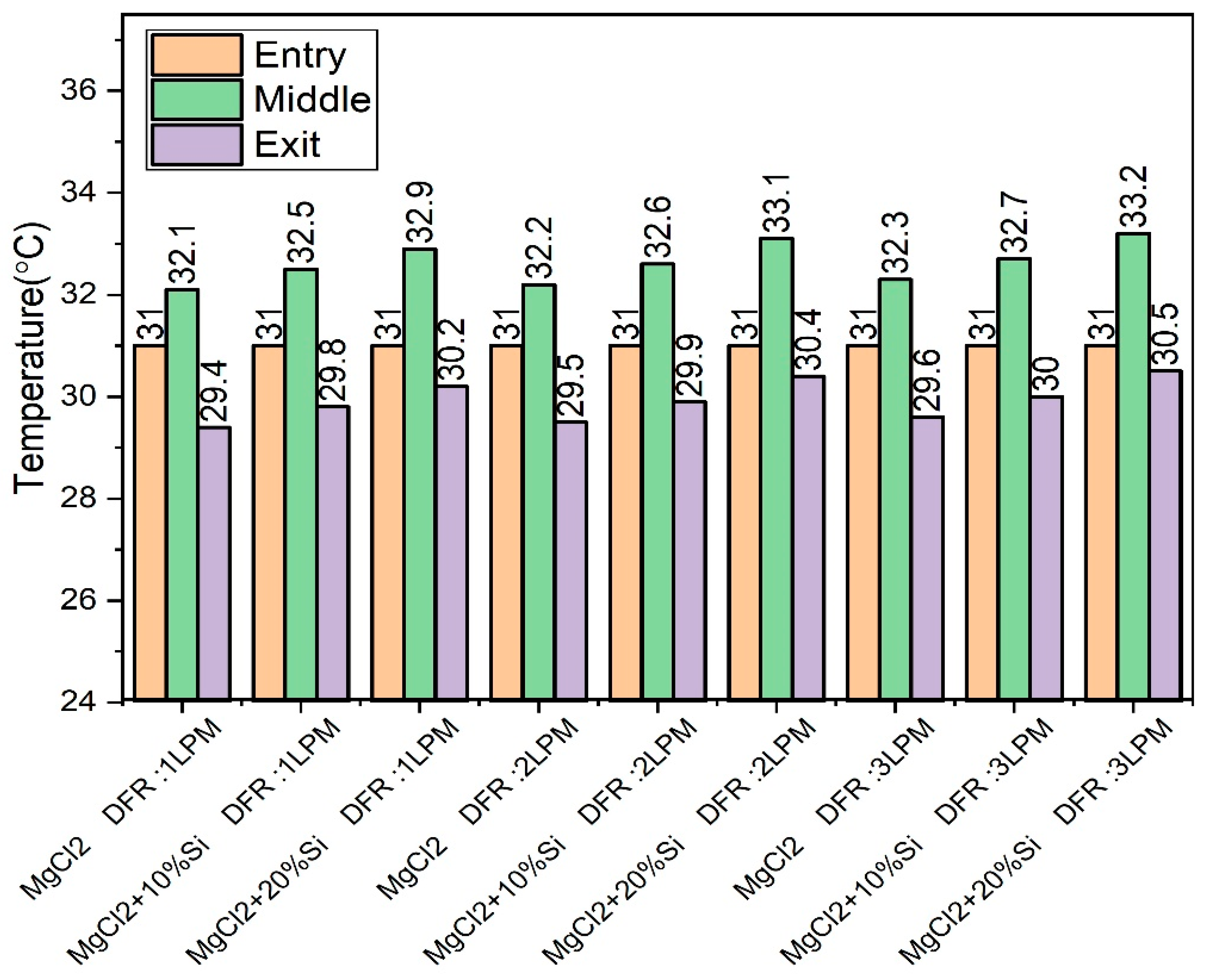
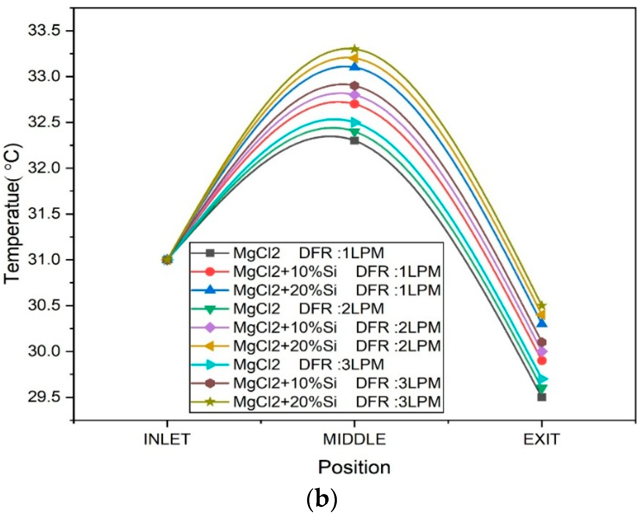
The variations in the air temperature at three positions—entry, middle, and exit—within the crossflow heat exchanger following dehumidification and post-cooling was analyzed for the different desiccant solutions and desiccant flow rates (DFRs), and are shown in Figure 4. (The specific values for each data point are annotated to improve clarity on how the desiccant type and flow rate affected the intermediate and outlet temperature.) The experimental setup incorporated MgCl2-based desiccants, both in pure form and in combination with silica (10% and 20%), with DFR values of 1, 2, and 3 LPM. Across all the conditions, a consistent trend was observed: the middle temperature was the highest, followed by the entry, and the exit temperature was the lowest. This pattern reflects the internal dynamics of the heat exchanger. The initial rise in temperature from the entry to the middle section suggests heat gain due to the exothermic dehumidification process, where moisture-laden air interacts with the desiccant. In contrast, the temperature drop from the middle to the exit demonstrates the effectiveness of the post-cooling mechanism, likely involving chilled water or an air-based secondary cooling system. When the desiccant flow rate was increased while maintaining a constant cooling water flow rate, the exit temperature of the air was observed to rise. While the test described a rise in the outlet temperature with an increased desiccant flow rate, Figure 4 presents these values more distinctly for better interpretation. This occurred because the increase in the desiccant flow rate enhanced the dehumidification process, leading to greater moisture removal from the air. As a result, more heat was released during the absorption of moisture, which raised the air temperature immediately after the dehumidification stage. This warmer air then entered the cooling coil (or air cooler). However, due to the higher inlet air temperature and the fixed capacity of the cooling water circuit, the cooling effectiveness was reduced. Consequently, the air could not be cooled to the same extent as with lower inlet temperatures, leading to a higher final air exit temperature from the cooling section. Nevertheless, although the air temperature increased immediately after dehumidification, the subsequent cooling process still reduced the air temperature to a level that could meet indoor thermal comfort requirements. Thus, despite the increase in the air exit temperature with higher desiccant flow rates, the overall system could still maintain acceptable comfort conditions in the conditioned space. The increase in the intermediate temperature was notably higher with an increasing silica gel concentration compared to a mere increase in the desiccant flow rate, reflecting the enhanced heat release due to intensified dehumidification.
The addition of silica gel to magnesium chloride (MgCl2) enhanced the overall dehumidification performance by combining the strengths of both desiccants. MgCl2, a hygroscopic salt, is highly effective at absorbing moisture due to its strong affinity for water and ability to undergo deliquescence at high relative humidity levels. Silica gel, on the other hand, adsorbs moisture physically on its large internal surface area and remains in a solid state throughout the process. When used together, silica gel can act as a structural support and stabilizer for MgCl2, preventing agglomeration or liquid pooling while also adsorbing additional moisture. A 20% addition of silica gel was observed to maximize the dehumidification, and subsequently, the temperature rise after dehumidification was also higher, and that post-dehumidification was lower. A silica gel concentration above 20% showed increased desiccant viscosity, resulting in poor wettability over the honeycomb surface and reduced dehumidification uniformity. Hence, the study was limited to a maximum of 20% silica gel.
Quantitatively, for a desiccant flow rate of 3 LPM, the temperature rise after dehumidification increased from 1.3 °C for pure MgCl2 to 1.7 °C for the MgCl2 + 10% silica gel and further to 2.2 °C for the MgCl2 + 20% silica gel. Similarly, the post-dehumidification air temperatures (i.e., after the cooling stage) were 29.6, 30, and 30.5 °C for those cases, respectively. This confirms that while the hybrid desiccant configuration enhanced moisture removal, it also led to a greater thermal load, which was partially mitigated by the post-cooling unit.

3.1.2. Cooling Water Flow Rate

In desiccant-based air conditioning systems, the dehumidification process is exothermic in nature, which means that it releases heat when moisture is removed from the air. This heat is generated primarily due to the latent heat of condensation as water vapor is adsorbed or absorbed by the desiccant material. While a portion of this heat is retained by the desiccant itself, the major share is transferred to the process air, significantly raising its temperature after dehumidification. The elevated air temperature immediately after dehumidification is not suitable for direct supply to conditioned spaces, as it may compromise thermal comfort and increase the cooling load on the down-stream components. Therefore, post-dehumidification cooling is essential to bring the air back to an acceptable temperature before it enters the occupied zone.
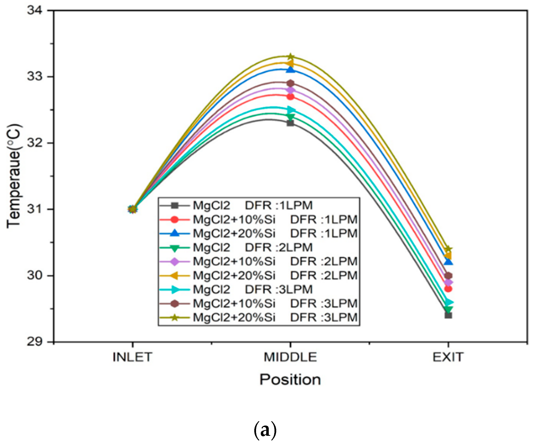
In the present study, post-dehumidification cooling is achieved using a crossflow plate-type heat exchanger, in which the cooling water flows from top to bottom, counter to or perpendicular to the direction of airflow. As the warm, moisture-reduced air passes through the exchanger plates, heat is transferred from the air to the water, effectively lowering the air temperature before it exits the system. While increasing the cooling water flow rate enhances the convective heat exchange, the overall cooling effectiveness is more significantly influenced by the temperature and humidity of the incoming air, both of which depend on the air velocity and desiccant type. Thus, optimizing the upstream dehumidification is critical for improving the post-cooling performance. It is observed that the rate of heat transfer—and therefore the effectiveness of cooling—is strongly influenced by the cooling water flow rate. Figure 5a,b shows the exit temperature plotted for cooling water flow rates maintained at 1 LPM and 3 LPM respectively. When the cooling water flow rate is increased, the convective heat transfer coefficient on the water side increases. This enhances the thermal gradient between the warm air and the cooler water, and produces a higher overall heat transfer, resulting in a lower exit air temperature. Conversely, at lower water flow rates, the heat removal from the air is less efficient due to the limited thermal capacity and lower convective heat transfer, leading to higher air exit temperatures. This condition may not sufficiently reduce the air temperature to levels required for indoor comfort, particularly in hot and humid climates. Thus, controlling the cooling water flow rate becomes a critical parameter in optimizing the thermal performance of the system and ensuring that the cooled, dehumidified air meets the design conditions for occupant comfort.

3.1.3. Air Velocity

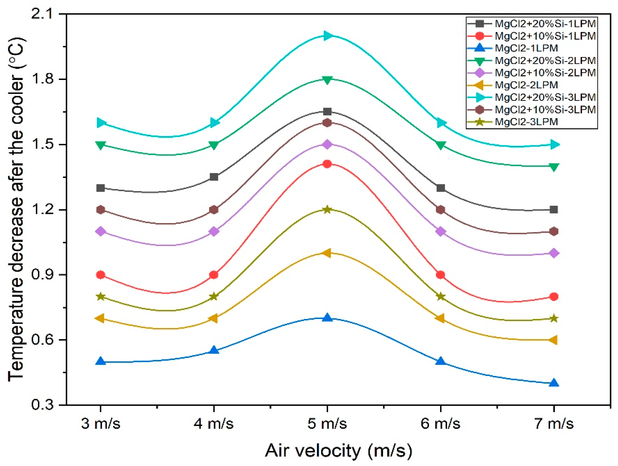
Figure 6 shows how the temperature decreases after the cooler, varying with the air velocity (3–7 m/s) for different combinations of desiccants (MgCl2 alone and MgCl2 with 10% or 20% silica gel) and different desiccant flow rates (1, 2, and 3 LPM).
It is observed that for all desiccant variants, the temperature drop after the cooler initially increases with a rising air velocity, reaches a maximum at an optimal velocity, and then decreases as the air velocity is increased further. Across all desiccant combinations and desiccant flow rates, the maximum temperature reduction occurs around 5 m/s air velocity. This suggests an optimum air velocity where the heat exchanger performs best, balancing the residence time and turbulence. At lower velocities, although the residence time is high, the heat transfer suffers due to laminar flow and weaker air-side convective heat transfer. At higher velocities (>5 m/s), the air passes too quickly through the heat exchanger, reducing the contact time and lowering the overall heat transfer despite increased turbulence. From Figure 6, it is observed that as the air velocity increases from 3 m/s to 7 m/s, the exit temperature decreases across all the tested desiccant configurations. Furthermore, increasing the silica content from 10% to 20% results in a slightly lower exit temperature. For instance, at 3 m/s and a 2 LPM desiccant flow rate, the exit temperature for pure MgCl2 is 31.8 °C, while it reduces to 30.6 °C and 30.1 °C for MgCl2 + 10% silica gel and MgCl2 + 20% silica gel, respectively This reduction can be attributed to the improved moisture absorption and thermal stability of the hybrid desiccant blend, which enhances the cooling performance post-dehumidification.
For a given air velocity and water flow rate, the desiccant combinations with silica gel (both 10% and 20%) show a greater temperature decrease than the MgCl2 alone. This is due to the better dehumidification upstream, resulting in hotter, drier air entering the cooler, since this air has a lower specific humidity, which enhances the sensible cooling, leading to greater observed temperature drops. Increasing the silica gel from 10% to 20% further improves the cooling performance at every velocity. The higher silica gel content improves moisture removal, leading to higher air temperatures after dehumidification, which in turn increases the temperature gradient across the heat exchanger, thereby enhancing the cooling effectiveness. Increasing the silica gel concentration enhances the dehumidification performance due to the greater exposed surface area available for moisture adsorption. On the other hand, increasing the desiccant flow rate alone does not significantly impact the moisture removal capacity, as it does not change the silica content or its surface area.

3.2. Moisture Removal Rate (MRR)

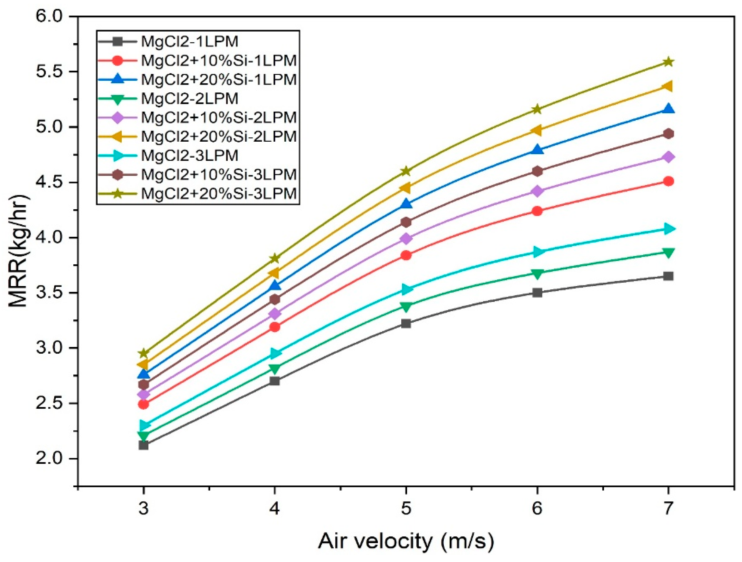
The moisture removal rate (MRR) is significantly influenced by the air velocity passing through the dehumidification system. The general trend observed is that at low air velocities, the MRR tends to be lower. Although the air remains in contact with the desiccant for a longer duration (increased residence time), the volume of air processed per unit time is small, thereby limiting the total moisture removed. As the air velocity in-creases, the MRR initially increases due to the higher volumetric flow rate of the moist air, allowing for more water vapor to be brought into contact with the desiccant per unit time, and enhances the turbulence, improving the mass transfer coefficients and promoting better moisture diffusion from the air to the desiccant. The nature of variation is clearly depicted in Figure 7. At lower desiccant flow rates, the MRR is limited due to the localized saturation of the desiccant in the contact area, which reduces the moisture gradient. As the desiccant flow rate is increased, the MRR improves because the fresh, unsaturated desiccant is continually brought into contact with the moist air. Hence, the desiccant can carry away the absorbed moisture efficiently, maintaining a high absorption capacity. MgCl2 alone is a highly hygroscopic salt with good moisture absorption capacity, especially under high-humidity conditions. However, it tends to become diluted (liquefied) as it absorbs moisture, which may limit its long-term performance. The addition of silica gel (10% and 20%) enhances the MRR due to the increased total adsorption surface area from the porous structure of silica gel. It adsorbs moisture physically, complementing the chemical absorption by MgCl2. It also helps stabilize MgCl2, preventing channeling or saturation hotspots by distributing the absorbed moisture more evenly. As the silica gel content increases (from 10% to 20%), the MRR consistently improves, provided the system maintains sufficient airflow and desiccant circulation. The higher the silica gel content, the greater the moisture-holding capacity, especially under fluctuating humidity levels. The experimental results indicate that a variation in the cooling water flow rate between 1 LPM and 3 LPM has a minimal impact on the moisture removal rate (MRR). In the present work, under constant desiccant and airflow conditions, the MRR values vary only between 1.18 kg/h and 1.21 kg/h across this cooling water flow range, a difference of less than 0.05 kg/h. This suggests that the MRR is predominantly influenced by the desiccant–air interaction rather than the cooling water side, which primarily affects the exit air temperature, not the humidity extraction. It can be concluded that the change in the cooling water flow rate in the post-cooling heat exchanger has no significant impact on the moisture removal rate (MRR) because moisture extraction primarily occurs in the dehumidifier, where the air interacts with the liquid desiccant. By the time the air reaches the post-cooler, most of the moisture has already been absorbed by the desiccant solution. The role of the air-to-water heat exchanger is mainly to reduce the dry-bulb temperature of the dehumidified air, improving thermal comfort or preparing it for further processing. Since this cooling step occurs after dehumidification, changes in the cooling water flow rate affect only the temperature of the air, not its humidity content.

3.3. Dehumidification Efficiency

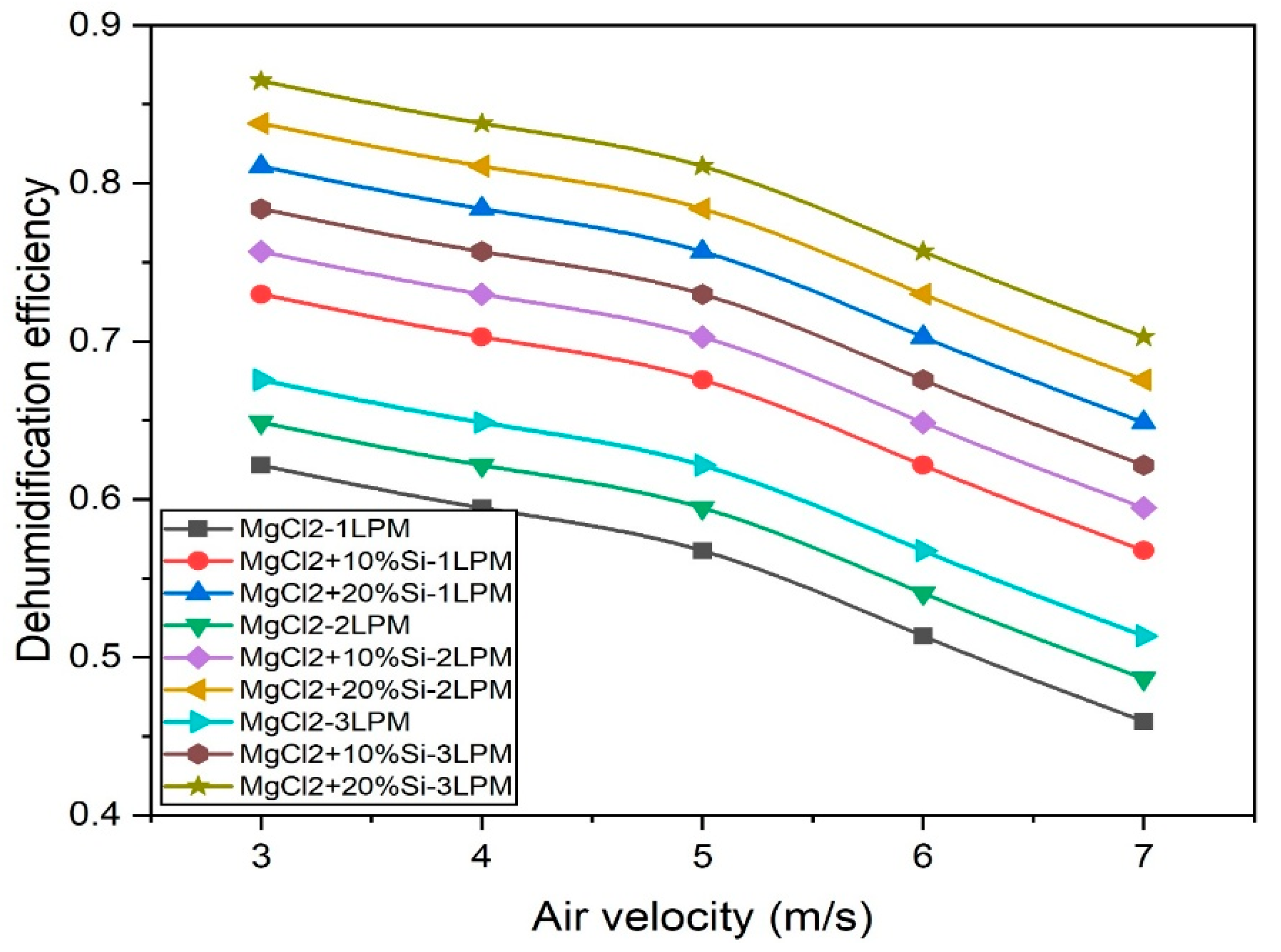
The variation in the dehumidification efficiency for the different desiccants tested is shown in Figure 8. Across all desiccant combinations and flow rates, the dehumidification efficiency consistently decreases with increasing air velocity. At lower air velocities, the moist air stays in contact with the desiccant for a longer time (increased residence time), allowing for more moisture to be absorbed, leading to a higher dehumidification efficiency. As the air velocity increases, the contact time between the air and the desiccant decreases. This reduces the opportunity for mass transfer, thereby lowering the overall moisture removal efficiency. Additionally, at higher velocities, the boundary layers are thinner, but the air moves too quickly for effective moisture diffusion into the desiccant. For a given desiccant composition, increasing the desiccant flow rate from 1 LPM to 3 LPM results in a higher dehumidification efficiency at all air velocities. At every flow rate and air velocity, adding silica gel (10% or 20%) to MgCl2 significantly enhances the dehumidification efficiency. It increases the effective surface area and introduces more adsorption sites, allowing for higher moisture uptake. The porous structure of the silica gel ensures rapid moisture diffusion, particularly beneficial when air passes quickly at higher velocities. Furthermore, the 20% silica gel blends consistently outperform the 10% blends across all operating conditions. The experimental data show that post-cooling has minimal influence on the dehumidification efficiency. In the present work, under identical desiccant and airflow conditions, the efficiency before post-cooling is measured at 84.2%, while after post-cooling it remains near that, at 84.6%. This confirms that the moisture extraction primarily occurs during the desiccant–air contact phase, and the cooling section mainly impacts the air temperature, not the humidity. Once the moist air has passed through the liquid desiccant, most of the moisture has already been absorbed. The post-cooling stage, typically carried out by an air-to-water heat exchanger, serves only to reduce the dry-bulb temperature of the dehumidified air for thermal comfort or system performance, not to enhance further moisture extraction.

3.4. Coefficient of Performance

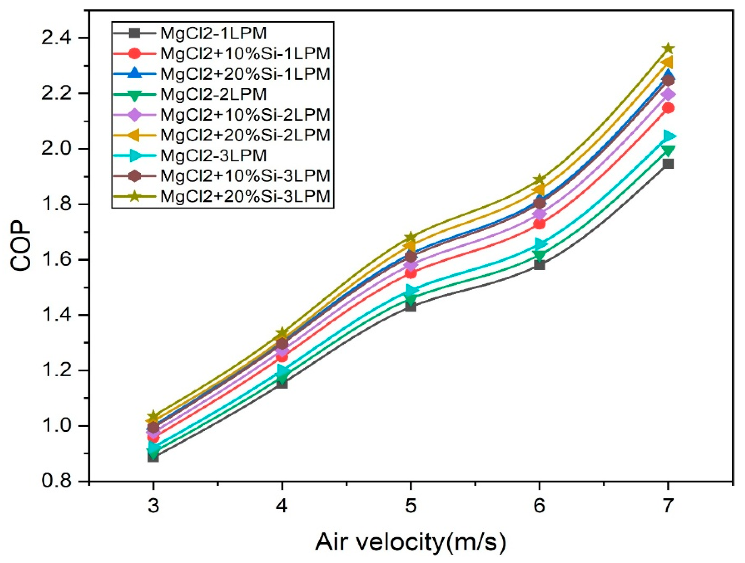
It is the ratio of the enthalpy change observed during dehumidification between the entry and the exit that provides the work input for running the blower and the pump. The performance of hybrid desiccant dehumidification systems can be effectively evaluated using the coefficient of performance (COP), which serves as a critical indicator of energy efficiency. The COP represents the ratio of the useful cooling effect achieved to the energy input required. In this context, the present study investigates the influence of three key parameters—air velocity, desiccant flow rate, and desiccant composition—on the COP, with particular emphasis on the role of silica gel-enhanced MgCl2-based desiccants. The findings are based on the experimental observations illustrated in the provided graph in Figure 9, which depicts the COP values across varying air velocities (3–7 m/s) and desiccant flow rates (1, 2, and 3 LPM) for different desiccant formulations. At an air velocity of 7 m/s, the COP is observed to be at its maximum due to the enhanced thermal processing of the air stream compared to lower velocities, such as 3 m/s and 4 m/s. This trend is primarily attributed to the higher mass flow rate of air at increased velocities, which results in more air being dehumidified per unit time. Consequently, the system handles a greater thermal load without a proportional rise in its energy consumption, thus improving the overall efficiency. Although higher air velocities may slightly reduce the dehumidification efficiency due to a reduced contact time between the air and desiccant, the increase in the total processed air volume outweighs this drawback. This leads to an overall enhancement in the system’s performance and energy effectiveness.
The desiccant flow rate is another factor that significantly impacts the COP. At each air velocity, an increase in the desiccant flow rate from 1 to 3 LPM consistently improves the COP. This improvement is a result of enhanced moisture absorption, as a higher flow rate supplies more desiccant to the contact surface, maintaining a stronger concentration gradient for mass transfer. The increased availability of fresh desiccant improves the rate and capacity of moisture removal, thereby reducing the thermal load on subsequent post-cooling stages. As the cooling demand decreases, the energy input required for achieving comfort conditions is minimized, resulting in a higher COP.
The role of desiccant composition is particularly noteworthy. Blending silica gel with MgCl2 significantly enhances the system’s COP. The addition of silica gel in 10% and 20% proportions improves the desiccant’s adsorption capacity due to the highly porous and hygroscopic nature of silica gel. The synergistic combination of physical adsorption (from the silica gel) and chemical absorption (from the MgCl2) accelerates the moisture removal process, allowing for more efficient dehumidification with a relatively lower thermal input. Among the tested samples, the formulation with 20% silica gel consistently demonstrates the highest COP across all air velocities and flow rates, highlighting its superior performance in terms of energy efficiency.
Comparative tables are provided to benchmark the performance of the present system. Table 4 presents a comparison with previous experimental studies. The present system demonstrates a superior moisture removal rate (MRR) and efficiency compared to earlier works, while maintaining a simple and stationary design, without relying on mechanical rotation or internal cooling mechanisms. The combination of MgCl2 with 20% silica gel in a crossflow arrangement, coupled with a post-cooling stage, delivers enhanced dehumidification performance while ensuring operational simplicity and energy efficiency. Unlike polymer-based rotary systems or internally cooled hybrid units, this setup operates passively with no moving parts, reducing maintenance and power requirements. These results highlight the potential of the proposed design for low-cost, energy-efficient, and scalable applications to passive or semi-active dehumidification systems, particularly for climate-adaptive storage or building environments.

4. Conclusions

The present study examined the parametric performance of a hybrid desiccant dehumidification system incorporating post-cooling using a crossflow water heat ex-changer. Among all the tested configurations, the desiccant blend of MgCl2 with 20% silica gel showed the most superior performance across all the parameters.
The dehumidification efficiency was observed to be the highest for the MgCl2 + 20% silica gel desiccant at a flow rate of 3 LPM, reaching a value of 0.86 at 3 m/s air velocity. In contrast, the lowest efficiency was noted for pure MgCl2 at 1 LPM, dropping to 0.61 at higher velocities. The efficiency declined steadily as the air velocity increased from 3 to 7 m/s, which was attributed to the reduced contact time between the air and the desiccant, thereby limiting the mass transfer of moisture.
The temperature reduction after post-cooling showed a clear peak around a 5 m/s air velocity for all the variants, indicating an optimal interaction between the air and the cooling water within the heat exchanger. The maximum temperature drop recorded was approximately 1.95 °C for the MgCl2 + 20% Si desiccant at 2 LPM, demonstrating effective heat rejection and highlighting the importance of post-cooling for maintaining indoor thermal comfort.
The COP, a critical indicator of energy efficiency, showed consistent improvement with an increasing air velocity. The highest COP of 2.36 was achieved for the MgCl2 + 20% Si desiccant at 3 LPM and 7 m/s air velocity, while the lowest COP, around 0.9, was observed for pure MgCl2 at 1 LPM and 3 m/s. This trend signifies that although the dehumidification efficiency may be reduced with an increased air speed, the total thermal performance of the system improves due to higher processing rates of the humid air, resulting in a better utilization of input energy.
The addition of silica gel to MgCl2 enhanced the overall moisture adsorption characteristics of the desiccant due to the increased porosity and surface area contributed by the silica. The 20% silica blend consistently outperformed the 10% blend and pure MgCl2 in terms of the dehumidification efficiency, MRR, temperature reduction after cooling, and COP. Increasing the desiccant flow rate from 1 to 3 LPM also significantly enhanced system performance by ensuring a greater mass of active desiccant for moisture absorption and heat transfer.
Overall, the study confirms that a well-optimized hybrid desiccant system with a silica gel addition and post-cooling can provide effective and energy-efficient dehumidification suitable for building HVAC applications. These findings can provide a foundation for the development of sustainable climate control systems capable of maintaining indoor air quality and thermal comfort while minimizing energy consumption. The study promotes SDG 7—Affordable and Clean Energy and SDG 11—Sustainable Cities and Communities. Future research will include real-time testing in HVAC systems within buildings, a long-term cyclic stability analysis of MgCl2–silica gel hybrids, and a CFD-based optimization of duct geometry to further enhance air dehumidification uniformity and energy savings.

Author Contributions

Conceptualization, M.N.; Formal analysis, L.S.; Investigation, L.S.; Data curation, N.K.; Writing—original draft, M.C.G.; Writing—review and editing, S.S.S.; Supervision, S.K. All authors have read and agreed to the published version of the manuscript.

Funding

This research received no external funding.

Institutional Review Board Statement

Not applicable.

Informed Consent Statement

Not applicable.

Data Availability Statement

Data are contained within the article.

Conflicts of Interest

The authors declare no conflict of interest.

References

  1. Fekadu, G.; Subudhi, S. Renewable energy for liquid desiccants air conditioning system: A review. Renew. Sustain. Energy Rev. 2018, 93, 364–379. [Google Scholar] [CrossRef]
  2. Rafique, M.M.; Gandhidasan, P.; Bahaidarah, H.M.S. Liquid desiccant materials and dehumidifiers—A review. Renew. Sustain. Energy Rev. 2016, 56, 179–195. [Google Scholar] [CrossRef]
  3. Shukla, D.L.; Modi, K.V. A technical review on regeneration of liquid desiccant using solar energy. Renew. Sustain. Energy Rev. 2017, 78, 517–529. [Google Scholar] [CrossRef]
  4. Jain, S.; Bansal, P.K. Performance analysis of liquid desiccant dehumidification systems. Int. J. Refrig. 2007, 30, 861–872. [Google Scholar] [CrossRef]
  5. Liu, X.H.; Chang, X.M.; Xia, J.J.; Jiang, Y. Performance analysis on the internally cooled dehumidifier using liquid desiccant. Build. Environ. 2009, 44, 299–308. [Google Scholar] [CrossRef]
  6. Gandhidasan, P. A simplified model for air dehumidification with liquid desiccant. Sol Energy 2004, 76, 409–416. [Google Scholar] [CrossRef]
  7. Liu, X.H.; Yi, X.Q.; Jiang, Y. Mass transfer performance comparison of two commonly used liquid desiccants: LiBr and LiCl aqueous solutions. Energy Convers. Manag. 2011, 52, 180–190. [Google Scholar] [CrossRef]
  8. Mohammad, A.T.; Mat, S.B.; Sulaiman, M.Y.; Sopian, K.; Al-abidi, A.A. Historical review of liquid desiccant evaporation cooling technology. Energy Build. 2013, 67, 22–33. [Google Scholar] [CrossRef]
  9. Sharma, A.; Kaushal, R. Experimental investigation of a novel multi-channel flat plate liquid desiccant dehumidification system. Energy Sources, Part A Recover. Util. Environ. Eff. 2024, 46, 11148–11166. [Google Scholar] [CrossRef]
  10. Yin, Y.; Qian, J.; Zhang, X. Recent advancements in liquid desiccant dehumidification technology. Renew. Sustain. Energy Rev. 2014, 31, 38–52. [Google Scholar] [CrossRef]
  11. Bai, Z.; Chinnappan, A.; Deng, J.; Shu, C.-M.; Ghomi, E.R.; Yao, S.; Duan, X.; Chinnappan, B.; Ramakrishna, S. Recent progress in ionic liquids as desiccants for energy consumption in cooling applications. J. Mol. Liq. 2023, 383, 122033. [Google Scholar] [CrossRef]
  12. Abdel-Salam, A.H.; Simonson, C.J. State-of-the-art in liquid desiccant air conditioning equipment and systems. Renew. Sustain. Energy Rev. 2016, 58, 1152–1183. [Google Scholar] [CrossRef]
  13. Wen, T.; Lu, L.; Li, M.; Zhong, H. Comparative study of the regeneration characteristics of LiCl and a new mixed liquid desiccant solution. Energy 2018, 163, 992–1005. [Google Scholar] [CrossRef]
  14. Pratama, N.N.; Ariyadi, H.M.; Waluyo, J.; Hayatullah, W. Numerical Performance Evaluation of Aqueous LiCl and CaCl2 Solutions as Liquid Desiccants in Dehumidification Systems. Eng. Proc. 2024, 67, 24. [Google Scholar] [CrossRef]
  15. Kumar, N.; Ganesha, A.; Girish, H.; Harsha, A.K.; Shekar, M.V.; Salins, S.S. The synergy of hybrid desiccants and membrane-assisted techniques for enhancing dehumidifier efficiency. Int. J. Sustain. Eng. 2024, 17, 1140–1153. [Google Scholar] [CrossRef]
  16. Fahad, F.G.; Al-Humairi, S.T.; Al-Ezzi, A.T.; Majdi, H.S.; Sultan, A.J.; Alhuzaymi, T.M.; Aljuwaya, T.M. Advancements in Liquid Desiccant Technologies: A Comprehensive Review of Materials, Systems, and Applications. Sustainability 2023, 15, 14021. [Google Scholar] [CrossRef]
  17. Abdelgaied, M.; Saber, M.A.; Bassuoni, M.M.; Khaira, A.M. Adsorption air conditioning: A comprehensive review in desiccant materials, system progress, and recent studies on different configurations of hybrid solid desiccant air conditioning systems. Environ. Sci. Pollut. Res. 2023, 30, 28344–28372. [Google Scholar] [CrossRef]
  18. Shivaprasad, K.V.; Roy, S.; Giampieri, A.; Smallbone, A.; Roskilly, A.P. Experimental and numerical investigation to optimise liquid desiccant system for advanced air conditioning. Sci. Rep. 2025, 15, 7151. [Google Scholar] [CrossRef]
  19. Guan, B.; Zhang, Q.; Li, M.; Zhang, T.; Liu, X.; Wang, X. Investigation on liquid desiccant regeneration for advanced air-conditioning: Aerodynamic thermal method versus mechanical vapor recompression method. Energy Convers. Manag. 2024, 305, 118253. [Google Scholar] [CrossRef]
  20. Lowenstein, A. Review of Liquid Desiccant Technology for HVAC Applications. HVAC&R Res. 2008, 14, 819–839. [Google Scholar] [CrossRef]
  21. Riffat, S.B.; Shehata, H.A.; Srivastava, N.C. The desiccant air-conditioning system. Int. J. Ambient Energy 2004, 25, 163–168. [Google Scholar] [CrossRef]
  22. Zheng, X.; Ge, T.S.; Wang, R.Z.; Hu, L.M. Performance study of composite silica gels with different pore sizes and different impregnating hygroscopic salts. Chem. Eng. Sci. 2014, 120, 1–9. [Google Scholar] [CrossRef]
  23. Kumar, S.; Salins, S.S.; Reddy, S.V.K. Influence of the velocity ratio and rotational speed on the polymer based desiccant dehumidifier. Discov. Appl. Sci. 2025, 7, 687. [Google Scholar] [CrossRef]
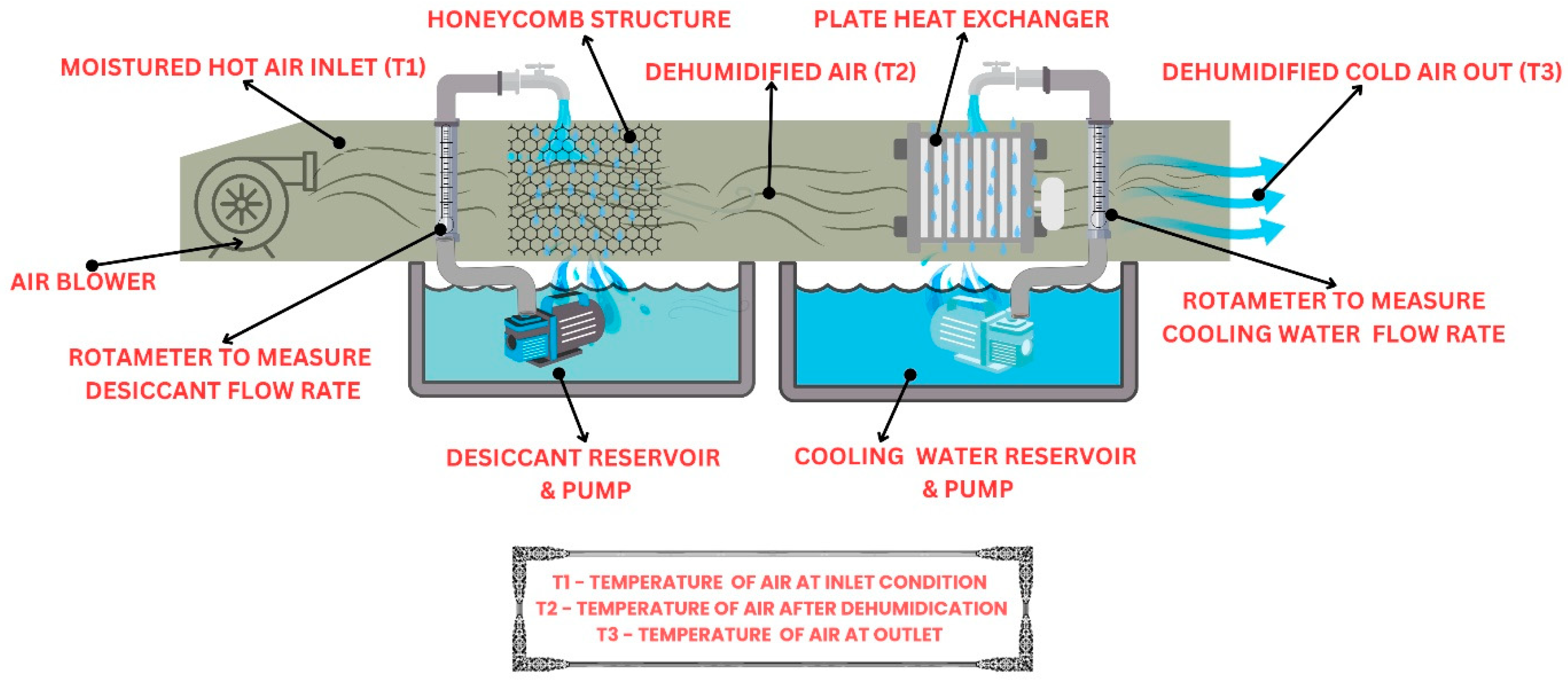
Figure 1. Schematic diagram of experimental setup.
Sustainability 17 07805 g001
Figure 2. Experimental setup—front view.
Sustainability 17 07805 g002
Figure 3. Honeycomb-structured celdek packing and plate heat exchanger.
Sustainability 17 07805 g003
Figure 4. Variation in air temperature at different locations for tested desiccant mixtures.
Sustainability 17 07805 g004
Figure 5. Variation of in air exit temperature for cooling water flow rates of (a) 1 LPM and (b) 3 LPM.
Sustainability 17 07805 g005aSustainability 17 07805 g005b
Figure 6. Variation in temperature reduction in cooler.
Sustainability 17 07805 g006
Figure 7. Variation in MRR with air velocity for different desiccant combinations.
Sustainability 17 07805 g007
Figure 8. Variation in dehumidification efficiency with air velocity for different desiccant combinations.
Sustainability 17 07805 g008
Figure 9. Variation in COP with air velocity for different desiccant combinations.
Sustainability 17 07805 g009
Table 1. Specification of instruments used.
InstrumentMaker/ModelRangeAccuracyResolution
Air blowerHavell’s turbo force0.4–7 m/s
ThermocoupleChromel-Alumel (K-type)0–200 °C ± 0.1 °C0.1 °C
RotameterTransforum engg5 kg/cm2 ± 3% FS0.1 LPM
HygrometerUNI-TUT 3330–100% ± 2.5% RH0.1% RH
Temperature indicatorSystem Controls0–300 °C
DigitalWork zone AVM-030.45 m/s ± 0.1 m/s0.01 m/s
Variable frequency driveMitsubhi D7000–50 Hz
Table 2. Measuring instruments and their locations.
MeasurementLocationDevice
Air TemperatureEntry—after honeycomb packaging—and exit.K-type thermocouple
Air VelocityInlet and exit of air passage duct.Anemometer
Relative HumidityEntry—after honeycomb packaging—and exit.Hygrometer
Desiccant Flow RateBefore honeycomb packaging (attached to the duct).Rotameter
Cooling Water Flow RateAfter honeycomb packaging (attached to the duct).Rotameter
Note: All instruments were calibrated at Manipal Institute’s certified lab in March 2025 before experimental trials. This ensured data integrity throughout the study.
Table 3. Experimental parameters.
ParameterParameter Variation
Liquid DesiccantMgCl2 (30% concentration)
MgCl2 (30% concentration) + silica gel (10% concentration)
MgCl2 (30% concentration) + silica gel (20% concentration)
Air Velocity3 m/s, 4 m/s, 5 m/s, 6 m/s, and 7 m/s
Cooling Water Flow Rate1 lpm, 2 lpm, and 3 lpm
Desiccant Flow Rate1 lpm, 2 lpm, and 3 lpm
Table 4. Comparison with experimental studies in literature.
ReferenceDesiccant SystemEfficiencyCOPMRRNotes
[1]Silica gel (packed bed)72%1.120.21 g/sStandard passive adsorption system
[4]LiCl (flat-plate channel)80%1.60.26 g/sHybrid crossflow geometry
[5]Internally cooled CaCl278%2.90.28 g/sEnhanced hybrid cooling design
[23]Polymer rotary desiccant system83.7%5.360.23 g/sVelocity-tuned polymer wheel (rotary)
This studyMgCl2 + 20% silica gel86%2.360.33 g/sStationary crossflow + post-cooling setup
Disclaimer/Publisher’s Note: The statements, opinions and data contained in all publications are solely those of the individual author(s) and contributor(s) and not of MDPI and/or the editor(s). MDPI and/or the editor(s) disclaim responsibility for any injury to people or property resulting from any ideas, methods, instructions or products referred to in the content.