Article

Characterisation of End-of-Life Wind Turbine Blade Components for Structural Repurposing: Experimental and Analytic Prediction Approach

1
Faculty of Engineering, Leipzig University of Applied Sciences (HTWK Leipzig), 04277 Leipzig, Germany
2
Chalmers Industriteknik, 412 58 Göteborg, Sweden
3
Institute of Lightweight Engineering and Polymer Technology, Dresden University of Technology, 01307 Dresden, Germany
*
Authors to whom correspondence should be addressed.
Sustainability 2025, 17(17), 7783; https://doi.org/10.3390/su17177783
Submission received: 11 June 2025 / Revised: 14 August 2025 / Accepted: 26 August 2025 / Published: 29 August 2025

Abstract

The problem of end-of-life (EoL) fibre-reinforced polymer (FRP) wind turbine blades (WTBs) poses a growing challenge due to the absence of an integrated circular value chain currently available on the market. A key barrier is the information gap between the EoL condition of WTB components and their second-life application requirements. This study addresses this question by focusing on the spar cap, which is an internal structural component with high repurposing potential. A framework has been developed to determine the as-received mechanical properties of spar caps from different EoL WTB models, targeting repurpose in the construction sector. The experimental programme encompasses fibre architecture assessment, calcination processes and mechanical tests in both longitudinal and transverse directions of three different WTB models. Results suggest that the spar caps appear to retain their strength and stiffness, with no evidence of degradation from previous service life. However, notable variation in properties is observed. To account for this, a prediction tool is proposed to estimate the as-received mechanical properties based on practically accessible parameters, thereby supporting decision-making. The results of this study contribute to enabling the repurposing of EoL spar cap beams from the wind energy sector for applications in the construction sector.

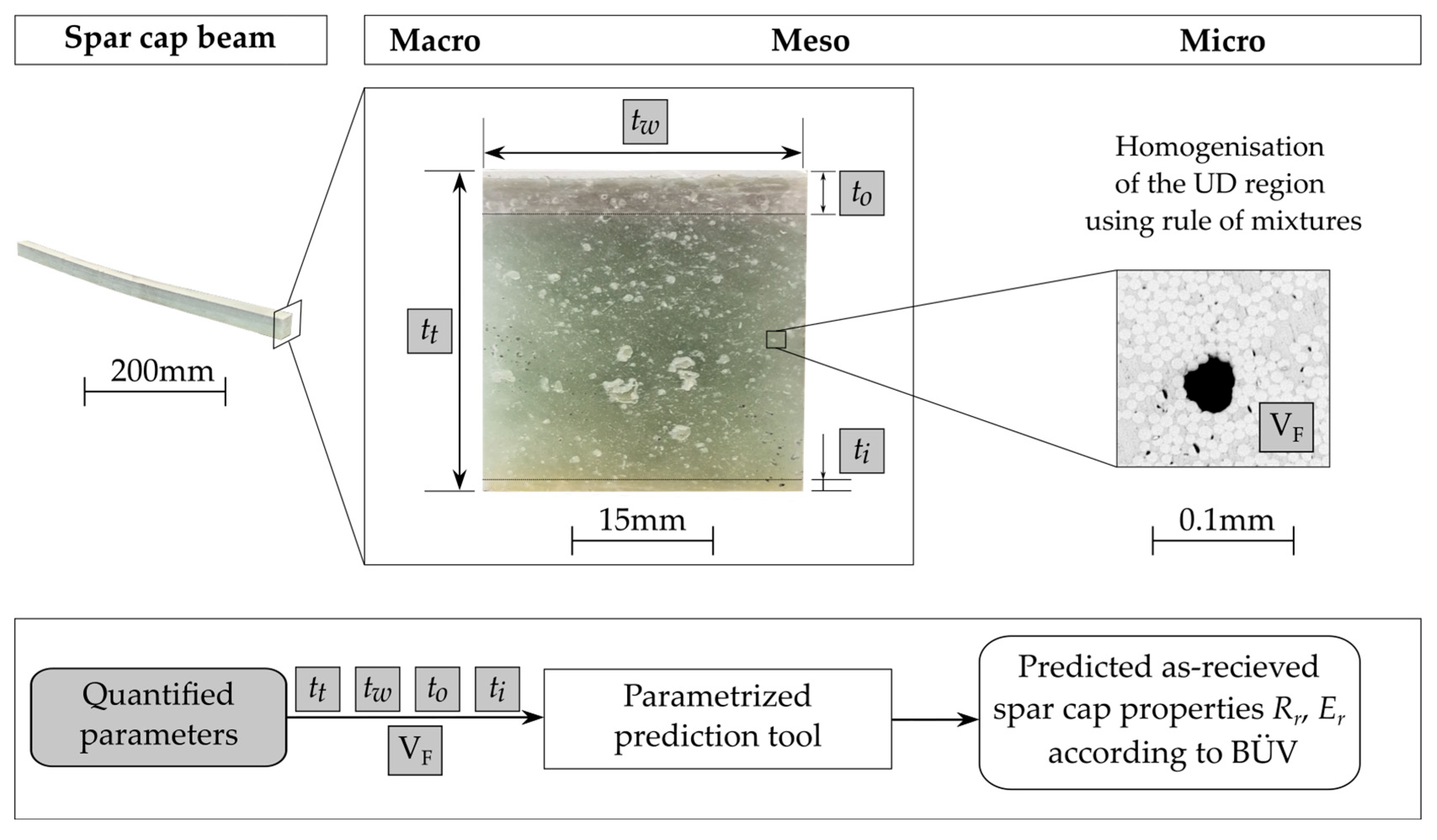
Graphical Abstract

1. Introduction

In recent decades, the wind energy industry has undergone rapid expansion, driven by the global shift toward renewable energy systems. Europe, particularly Germany, has led this transition [1]. Central to this growth are wind turbines (WTs), with wind turbine blades (WTBs) being critical components. WTBs are predominantly composed of composite materials such as glass fibre-reinforced polymer (GFRP) and carbon fibre-reinforced polymer (CFRP) [2], with GFRP being the dominant material due to its cost-effectiveness and structural properties [3]. While composites offer structural advantages, their end-of-life (EoL) management remains problematic. WTB composites predominantly utilise thermoset matrices such as unsaturated polyester, epoxy, or vinyl ester resins [4], which form irreversible covalent bonds during curing, making them difficult to recycle [5]. Furthermore, structural and quality variations across manufacturers and production years [6], combined with the large-scale and complex composition, complicate recycling efforts [7]. This is particularly evident in the case of GFRPs, where the use of cost-effective fibres reduces the economic motivation for recycling [8].
The urgency is further intensified by the 20–25 year service life of WTs [9], leading to a growing number of EoL WTBs in Europe, given that a high number of installations took place in the early 2000s. By 2050, an estimated 7.6 million tonnes of EoL WTBs will require processing, with a significant share expected from Germany [10]. This volume underscores the need for EoL strategies that comply with environmental targets and regulations, including existing bans on landfill and incineration in Germany and proposed restrictions at the European level [7]. As a result, the wind energy sector is increasingly exploring alternative “R-strategies” for EoL management beyond conventional recycling. Strategic frameworks for extending the service life of EoL materials [11,12] outline a wide range of approaches, hierarchically arranged by increasing circularity, including reuse, repair, refurbish, remanufacture, and repurpose. Among these, repurposing offers relatively high environmental benefits [13]. Although no consensus exists on the optimal EoL strategy, it is widely recognised that different approaches can complement each other [14].
This study investigates the repurposing of EoL WTB materials in the construction sector. Repurposing is defined as the utilisation of a discarded product or its components in a new application with a different function [11]. This approach can extend the service life of materials, maintain structural integrity, and reduce the reliance on virgin resources, aligning with circular economy principles [15,16]. Prior research has demonstrated the effectiveness of repurposing composite structures [17] and specifically for EoL WTB components [18,19].
However, the scaling up of the repurposing strategy is emphasised as one important element in creating sustainable value chains [20]. Its implementation on an industrial scale is hindered by several barriers. Despite the growing interest in EoL solutions for WTB materials, detailed product data, including material composition, geometry, and structural layout, are often unavailable at the level of precision required for effective repurposing [2]. The variability in WTB designs across different WT models further complicates repurposing efforts [21]. According to the publicly accessible database Marktstammdatenregister (MaStR) [22], there are currently over 100 different WT rotor diameters, and consequently, over 100 different WTB models, in operation in Germany. Moreover, in addition to the length of the WTBs, the MaStR provides information on the WTB material and the WT commissioning year. Heavily defected, damaged or large WTBs pose logistical challenges, making direct reuse difficult and often necessitating segmentation for transport and handling [3]. Conclusively, the high variability in geometry, material composition, and quality among EoL WTBs limits standardisation. Furthermore, the as-received properties of EoL WTB materials are often not clear, necessitating extensive and time-consuming material characterisation to assess their suitability for structural repurposed applications [23,24].
To maximise repurposing potential while preserving material integrity, Joustra et al. [25] proposed a systematic sectioning approach tailored to the complex geometries of WTBs. It involves transverse direction (TD) cuts to divide WTBs into segments (Figure 1a, dotted lines), followed by longitudinal direction (LD) cuts (Figure 1b, dotted lines) to extract key components like spar cap beams and sandwich panels from the shear webs and aerodynamic shell. This approach is already applied by companies like Ventosmetodicos to recover these semi-finished components from various WTB models (Figure 1c).
Spar caps, which form the central focus of the present study, span the full length of WTBs, are mainly made of unidirectional (UD) fibres [2] and represent a significant portion of the composite mass, particularly in EoL GFRP WTBs [25,26]. As the main load-bearing elements, spar caps provide high strength and stiffness and are consistently present across different WTB models. These characteristics make them well-suited for large-scale structural repurposing, such as bending-loaded beam elements in housing, where they could serve as substitutes for timber beams (see Figure 1d). To ensure safety and performance, repurposing strategies must align with the BÜV recommendations valid in Germany for structural composites in the construction sector [27]. This requires a framework to evaluate the as-received mechanical properties of EoL spar caps [28].

1.1. Objectives (Os)

The challenges associated with repurposing EoL WTB materials shape the objectives of this study. The first objective (O1) is to develop a tailored framework that integrates established testing methods to evaluate manufacturing defects, damage states and the as-received mechanical properties of spar cap materials. The framework shall incorporate structured decision-making aligned with German industry standards to support the safe and reliable repurposing of EoL WTB components in the construction industry. The second objective (O2) involves applying the framework to selected EoL WTB spar cap components to characterise their as-received properties and compare mechanical properties across different WTB models. This analysis seeks to identify practically accessible parameters that influence the as-received mechanical properties of EoL WTB spar caps. These parameters serve as a foundation for the third objective (O3): the suggestion of a prediction tool that uses analytic methods to estimate the mechanical properties of spar cap beams. The tool is designed to enhance both the practicability and reliability of assessments for repurposing applications. Its analytical basis will be validated through bending tests conducted at the substructure scale.

1.2. Research Questions (RQs)

Accordingly, this article addresses the following research questions:
  • How can the mechanical condition of the EoL WTB spar cap be assessed, and which established methods are suitable for evaluating their mechanical properties and their potential for structural repurposing in the construction sector (RQ1)?
  • How do the as-received mechanical properties of EoL WTB spar caps vary across different WTB models, and which practically accessible parameters can be quantified to describe this variability (RQ2)?
  • How can a parameter-driven prediction tool reduce the need for extensive and expensive experimental testing while enabling the practical and reliable assessment of as-received spar cap properties (RQ3)?

2. Materials and Methods

2.1. EoL GFRP Spar Cap Materials from Different WTB Models

Calculations, based on forecast data for WTs in Germany, estimate a total EoL WTB material mass of 698 kt, including approximately 230 kt of spar cap material until 2050 [25]. Here, Enercon has the largest share of WTB mass [29]. The study investigates the GFRP spar cap material from the following Enercon EoL WTB models:
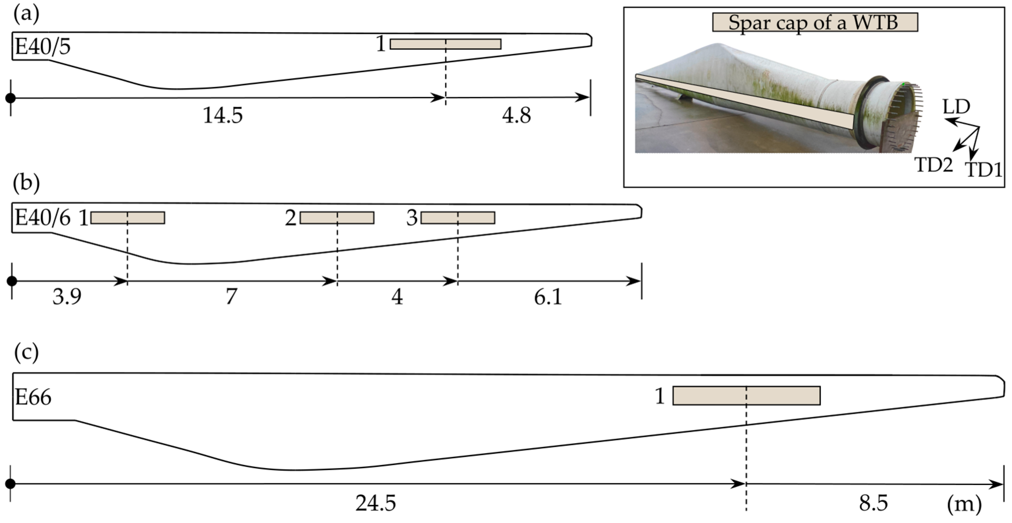
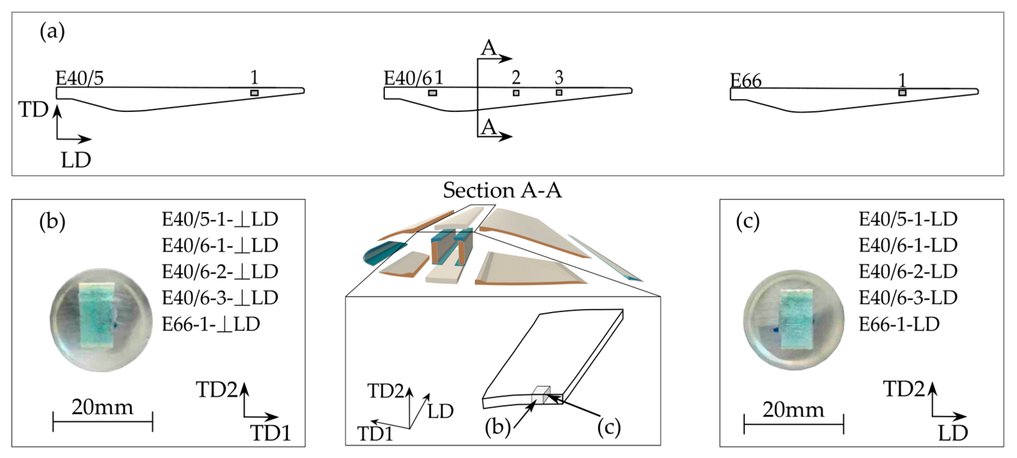
  • An EoL WTB from an E40/5 WT with an output of 500 kW, which was in use for approximately 20 years in the North of Germany (Emden), referred to as E40/5 WTB with a length of 19.3 m. The spar cap material from one location (1) of this WTB is analysed (Figure 2a).
  • An EoL WTB from an E40/6 WT, built in April 2002 but never commissioned, referred to as the E40/6 WTB with a length of 21 m. The reasons for non-operation are not disclosed to the authors. A complete WTB is available for investigation, and three locations (1, 2, 3) are defined for the extraction of spar cap material (Figure 2b). The E40/6 WTB represents a design evolution of the E40/5 WTB.
  • An EoL WTB from an E66 WT, referred to as E66 WTB, with a length of 33 m. It is sourced from a WT formerly located in Ihlow, Germany, and provided by an EoL WTB segment management facility. Neither the operator nor the facility specified the WTB’s service life. The spar cap material coming from one location (1) of the E66 WTB is analysed (Figure 2c).
As demonstrated in Figure 1b, all investigated WTB models exhibit an I-beam configuration. Due to confidentiality obligations, WT operators and WTB manufacturers declined to disclose material history information, including manufacturing processes, fibre architecture and service life conditions, to the authors following several requests.
Specifically, the WTB material mass and mix are determined using the MaStR [22] for the investigated E40/5, E40/6 and E66 WTB models. As of 1 January 2025, 4635 Enercon E40 WTBs (thereof 2862 E40/5 resp. 1773 E40/6 WTBs) are in operation, while 708 E40 WTBs (354 E40/5 resp. 354 E40/6 WTBs) are already decommissioned. Regarding the Enercon E66, 5052 WTBs are in operation, while 909 E66 WTBs are already decommissioned. Accordingly, the total mass of active WTB material (26,054 t) and EoL WTB material (4512 t) is calculated for the three analysed WTB models.

2.2. Categorising R-Strategies for the GFRP Spar Cap Material Stream

Based on the roadmap for sustainable value chains of EoL WTB materials, Lund and Madsen [7] identified different proper R-strategies for EoL WTB materials, such as recycling (mechanical, thermal, chemical) or structural repurposing. According to Potting’s [11] prioritisation, repurposing offers a higher level of circularity compared to recycling, covering both structural and non-structural repurposing applications. Therefore, the EoL spar cap material stream is categorised into three sub-streams: structural repurposing, non-structural repurposing, and recycling.
Structural repurposing in the construction industry involves the use of safety-critical structural components made from GFRP spar cap beams, which must meet stiffness and strength verification requirements according to various regulations. The primary objective of structural repurposing is to maintain structural integrity while maximising as-received mechanical potential of the composite material.
Non-structural repurposing refers to the use of GFRP beams in second-life applications such as furniture or other non-structural products. In such cases, the mechanical potential of the composite material is often under-utilised, not only because of reduced strength and stiffness, but also because key material properties may be unknown or insufficiently characterised. This lack of reliable data can limit or prevent structural applications, despite the material potentially retaining substantial as-received capacity.
For the recycling stream of GFRP beams, mechanical recycling appears most promising, involving the fragmentation of spar cap components. The recycled material may be used as filler material, for instance, in 3D printing filaments [30] or concrete [31]. Potential feedstocks for this recycling stream include production offcuts from the repurposing-related cutting processes, as well as severely defected or damaged beams that are unsuitable for both structural and non-structural repurposing streams.

2.3. Characterising As-Received Spar Cap Properties for R-Strategy Assignment

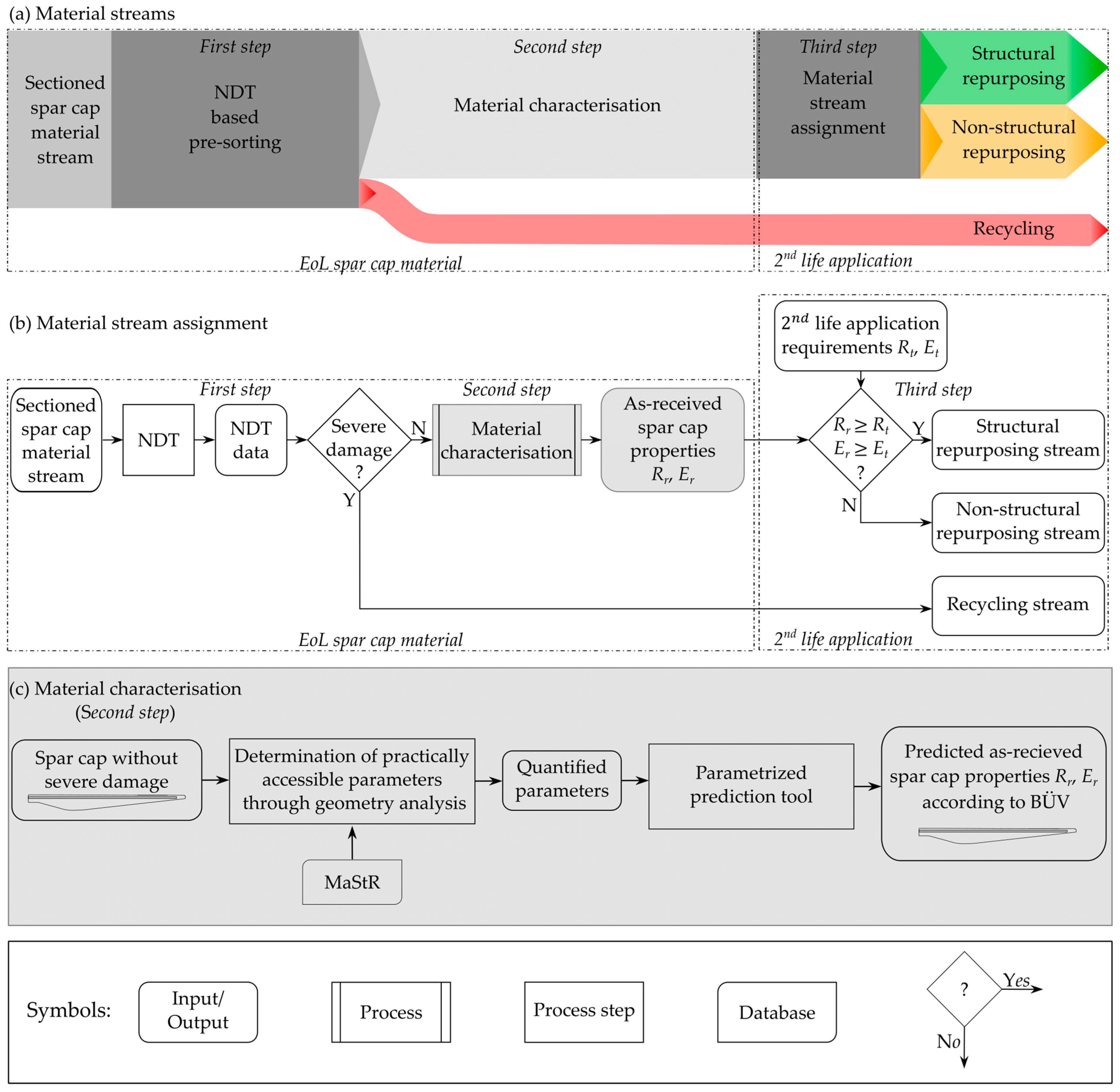
To support decision-making in alignment with German industry standards, a tailored framework is proposed (Figure 3). In the context of structural repurposing in the construction sector, the framework evaluates the unknown as-received material properties of EoL WTB spar cap components (addressing RQ1). Figure 3a shows the sectioned spar cap material stream as the input, which is subsequently divided into the three defined sub-streams. This material stream assignment process is further detailed in Figure 3b,c.
The first step involves a pre-sorting by identifying severe defects and damage in the EoL spar cap beams using selected non-destructive testing (NDT) methods. To ensure practicability, the process begins with on-site visual inspection for macro-level defects and damages. If mobile equipment capable of reliable on-site evaluation is available, advanced techniques such as ultrasound or thermography should be considered. By assessing the collected NDT data, severely defected and damaged material is excluded from repurposing and redirected to the recycling stream (Figure 3a,b).
In the second step, the material characterisation (Figure 3c) of the spar cap material without severe defects and damages is carried out in accordance with the BÜV recommendations valid in the construction sector entitled “Load-bearing plastic components in the construction industry” [27]. The BÜV suggests the characterisation of the as-received strength ( R r ) and modulus ( E r ) in both the 0° (LD) and 90° (TD) fibre directions and at two temperatures (23 °C and 67 °C (Appendix A)).
A parameter-driven prediction tool is proposed for characterisation. This tool is based on analytical methods and aims to efficiently predict the as-received properties required by the BÜV for untested spar cap beams. The tool’s parameters are estimated using non-destructive geometry analysis and assumptions informed by databases such as the MaStR. The prediction tool approach is described in detail in Section 2.4 and Section 3.2.
To assign the characterised EoL spar cap material to an appropriate repurposing stream, the third step involves comparing as-received mechanical properties R r and E r , with the specific requirements of potential second-life applications, R t and E t (Figure 3a,b). Structural repurposing is considered if R r   R t and E r   E t ; otherwise, non-structural repurposing is recommended ( R r   < R t ;   E r < E t ).

2.3.1. Sectioning for Recovering Spar Cap Specimens from EoL WTB

To identify the practically accessible parameters for the prediction tool, spar cap beams are retrieved from the EoL E40/5, E40/6 and E66 WTBs for material characterisation using the sectioning approach introduced by Joustra et al. [25] and further refined by Carrete et al. [32]. First, TD (transverse direction) cuts are performed to obtain EoL WTB segments from the whole WTB (Figure 4a). This first step is completed either by the EoL WTB segment management facility (E40/5, E66) or the WTB manufacturer (E40/6). Second, several LD (longitudinal direction) cuts are performed using a jigsaw to separate sandwich elements and shear web elements from the spar cap beams (Figure 4b). Excess material (bonding material between spar cap and shear web) is removed. Third, the spar cap beams are subjected to NDT in order to detect severe defects and damage (Figure 4c). In accordance with the proposed framework, visual inspections are employed qualitatively. Subsequently, the spar cap beams without severe defects and damage are subjected to further cut-processing to prepare LD and TD tensile test specimens (Figure 4d). The process entails the precise cutting of the spar cap beams into 200 mm square pieces. The 4 mm thick specimens are cut from the square-shaped spar cap pieces using LD and TD cuts with a water-cooled cutting machine equipped with a diamond-coated saw blade (Axitom, Stuers GmbH, Willich, Germany).

2.3.2. Material Characterisation of E40/5, E40/6 and E66 Spar Caps

  • Optical microscopy:
In microscopic analyses, the stacking sequence, fibre architecture and overall structural conditions are assessed. The five sampling locations are shown in Figure 5a. For each location, two cross-section orientations, perpendicular to LD (Figure 5b) and in LD (Figure 5c), are investigated. The spar cap materials are cut to approximately 20 mm × 10 mm × 10 mm specimens and moulded in resin to ensure better handling during polishing. The grinding procedure is performed using SiC papers, followed by a tailored polishing process for GFRP. For microscopy, a Zeiss AX10 light microscope (Carl Zeiss Microscopy GmbH, Jena, Germany) equipped with AxioVision software (AxioVs40x64 V 4.9.1.0 SP1 08-2013, Carl Zeiss Microscopy GmbH, Jena, Germany) is used.
  • Calcination:
Rectangular spar cap specimens are taken from each investigated WTB model, with sampling locations shown in Figure 5a. A minimum of four specimens is tested at each location. The determination of mass and volume fractions for both matrix and fibre is conducted according to ISO 1172 (calcination method) [33] and ISO 1183-1 (density determination for non-cellular plastics) [34] standard. The methodology employed involves the utilisation of the density of the glass fibre and the density of the epoxy resin matrix. It is assumed that the densities of fibre (ρf = 2.48 g/cm3, determined with a pycnometer from E40/5 spar cap material) and matrix (ρm = 1.19 g/cm3, as reported in [35]) are equivalent for all the investigated spar cap materials.
Prior to calcination analysis, the coatings and outer matrix plies on the top and bottom surfaces of the specimens are removed to isolate and accurately quantify the mass and volume fraction of the unidirectional (UD) area.
  • Tensile tests:
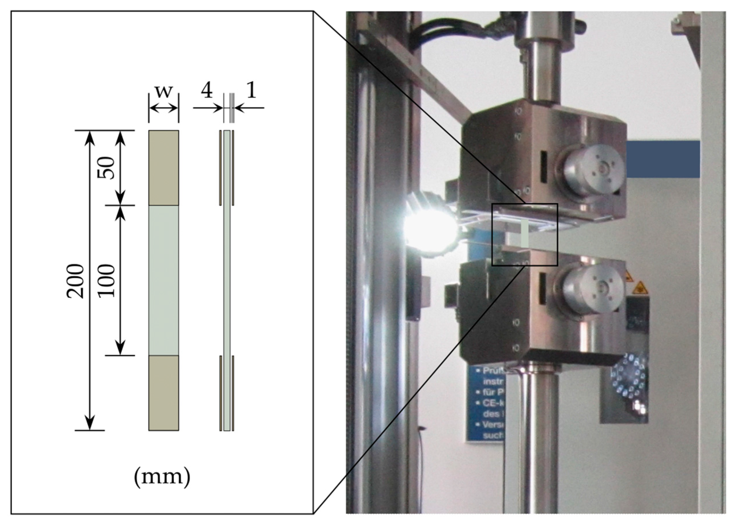
To improve the introduction of loads into the tensile test specimens, 1 mm thick bi-directional GFRP tabs are sandblasted and bonded using a two-part epoxy adhesive. The final dimensions of the specimen are a length of 200 mm and a thickness of 4 mm. The width w is determined by the thickness of the square-shaped spar cap material and ranges from approximately 15 mm to 25 mm, depending on the specimen’s location (Figure 6). All tensile test specimens are assessed for dimensional quality by verifying consistent thickness and width along their entire length. Fibre alignment in the LD specimens is confirmed through prior optical microscopy analysis.
Tensile tests are performed at room temperature (23 °C) using a universal testing rig (Z100, 100 kN capacity; ZWICK/ROELL, Ulm, Germany) equipped with a video extensometer. According to ISO 527-5 (Test conditions for unidirectional FRPs) [36], a quasi-static test speed of 2 mm/min is applied to LD specimens, and 1 mm/min to TD specimens to determine the as-received tensile strength R r , modulus E r and strain at failure ε r .
  • Differential scanning calorimetry:
In GFRP materials, temperature predominantly affects the polymer matrix, particularly as it approaches the glass transition temperature T g . In this temperature range, the polymer softens, which can lead to a reduction in both stiffness and strength. Therefore, T g of the unknown epoxy resin used in all analysed spar caps is determined in accordance with ISO 11357 (Differential scanning calorimetry) [37]. The specimens are subjected to a temperature programme ranging from 25 °C to 110 °C, with a constant heating rate of 10 K/min. All tests are conducted under 100% nitrogen (inert atmosphere).
  • Bending tests at spar cap beam component
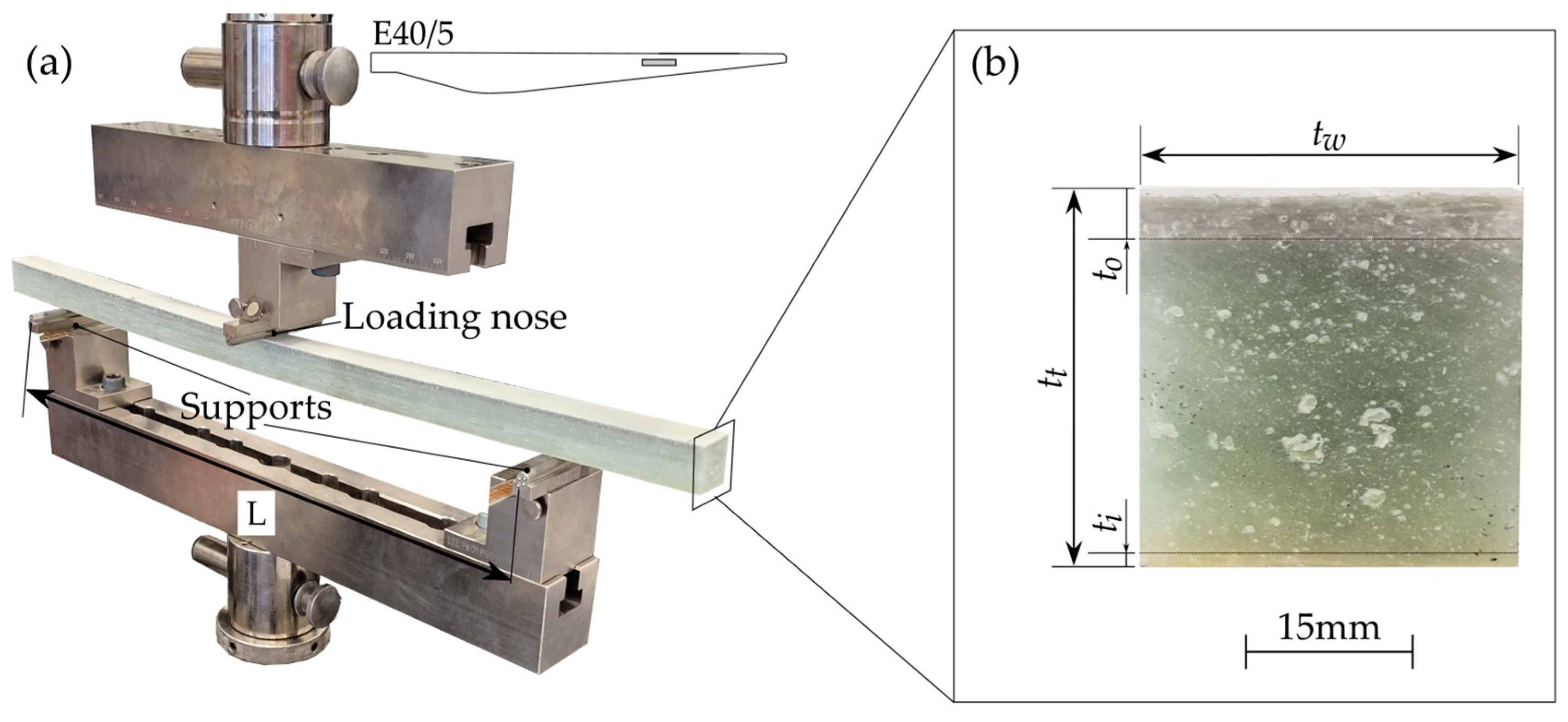
Two spar cap beam specimens, used for bending tests, are taken from an E40/5 WTB and measure 800 mm in length. The span L between the supports is 600 mm, and both the supports and the loading nose have a radius of 5 mm (Figure 7a). The specimens have a total thickness t t of approx. 33 mm and a width t w of approx. 35 mm. As shown in the cross-section of Figure 7b, a variation in material structure is visible: the outer region t o and the inner region t i differ from the structure in the central region.
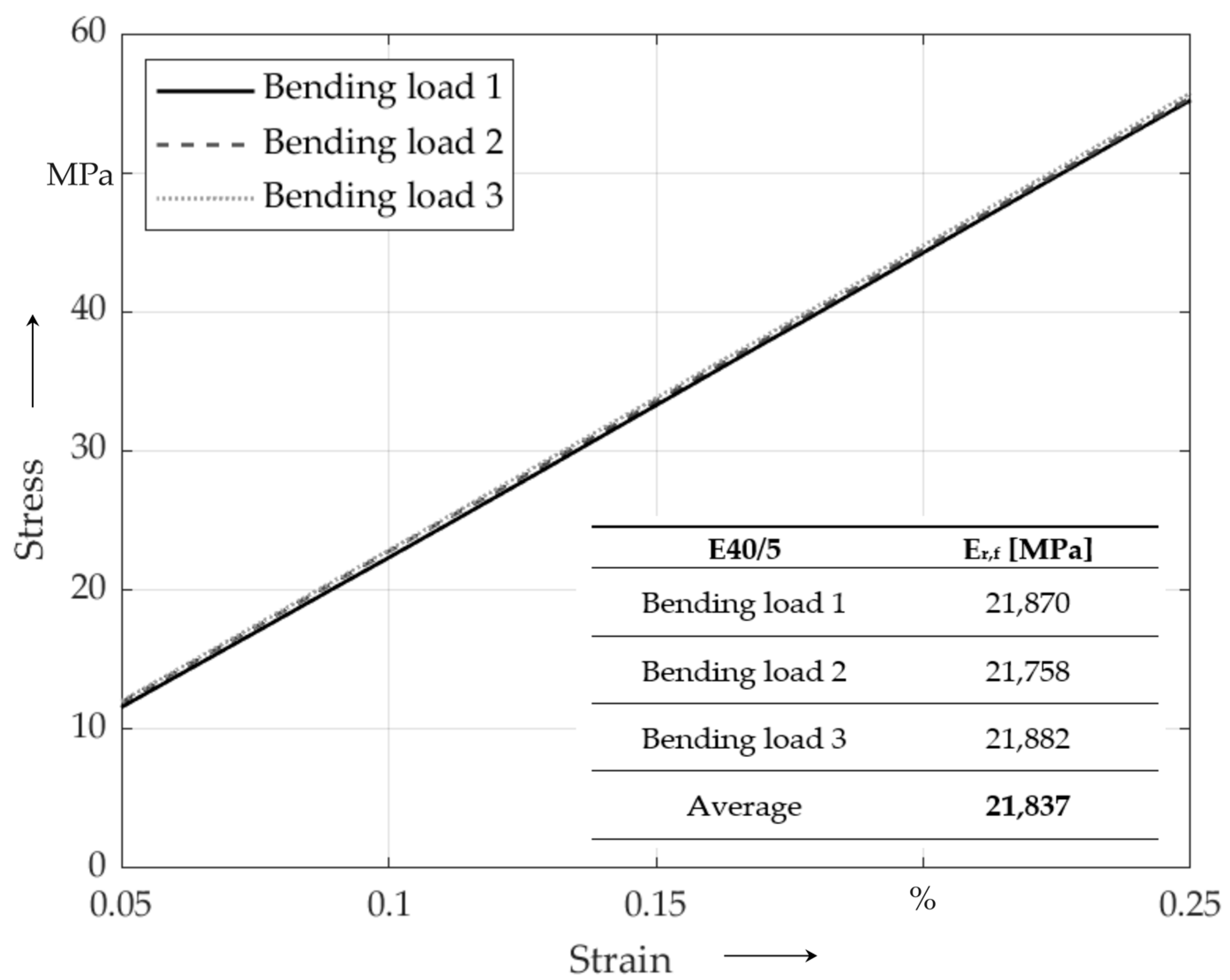
The bending tests are conducted on the basis of ISO 14125 (Determination of flexural properties) [38] to determine the stiffness of the spar cap beams, expressed as the flexural modulus. The beams are loaded until a strain of 0.25% is reached. The flexural modulus is calculated on three iterations for each specimen, based on the linear region of the stress–strain curve between strain values of 0.05% and 0.25%. The measurement of deflection is derived from the displacement of the loading nose, which is corrected by applying a calibration curve obtained from a reference test.

2.4. Prediction Tool for As-Received Spar Cap Properties

Since experimental characterisation of composite materials is both time-consuming and costly [39], this study proposes a prediction tool based on practically accessible parameters. These parameters are classified into the macro-, meso- and micro-scale and are determined through on-site geometry analysis to estimate the as-received material properties.
To ensure user-friendliness in practical contexts, the calculation process is incorporated in a spreadsheet program such as Microsoft Excel. This allows the tool to be used on standard smartphones directly on-site immediately after the cutting process. For usability and transparency, the calculations rely on analytical methods, eliminating the need for specialised finite element (FE) software. At the micro-scale, a homogenisation approach based on the rule of mixtures [40] is applied, using the fibre volume fraction V F as a key parameter to describe the structure of the UD spar cap. The value of V F is estimated from experience with experimental data on EoL spar cap material, with ranges conservatively defined according to the available data.
E C = E F V F + E M ( 1 V F )
The following assumptions are made for the prediction tool:
  • The composite consists of matrix and fibre materials with isotropic linear-elastic mechanical properties. The material properties of the matrix (epoxy resin, with a Young’s modulus of E M = 3.78 GPa) and the glass fibre (with a Young’s modulus of E F = 73 GPa) were obtained [40].
  • There is a perfect bonding between the fibres and matrix material.
  • All fibres in the UD area are perfectly oriented in LD without any misalignment.
  • The fibre volume fraction has a constant value in the UD area.

3. Results

Visible inspection shows that the gelcoat resin, which protects against environmental exposure, exhibits no visible signs of damage on any of the investigated EoL WTB components. However, spar cap beams that are damaged during the sectioning process are excluded from further characterisation.

3.1. Material Characterisation Results of E40/5, E40/6 and E66 Spar Caps

3.1.1. Microscopic Analysis

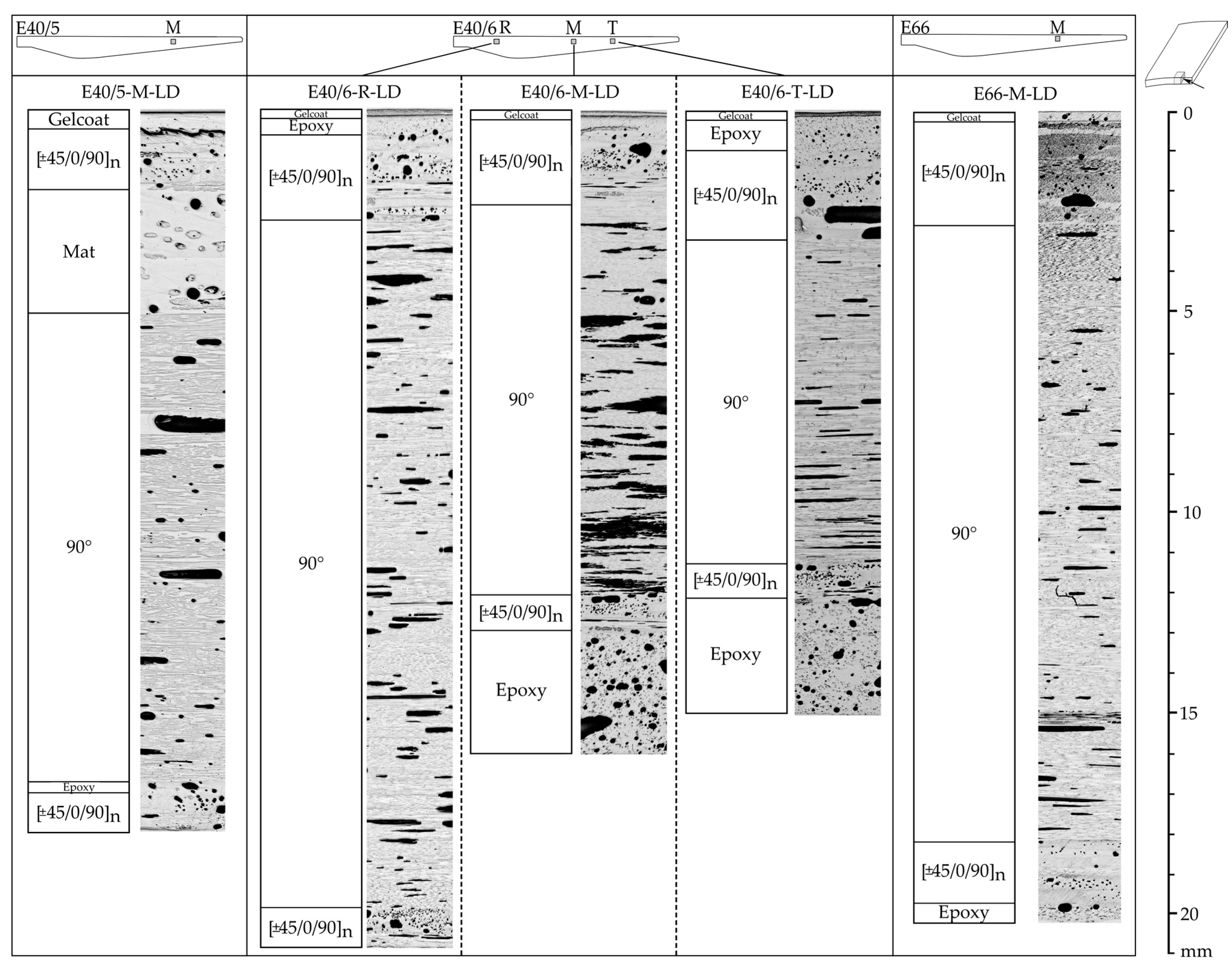
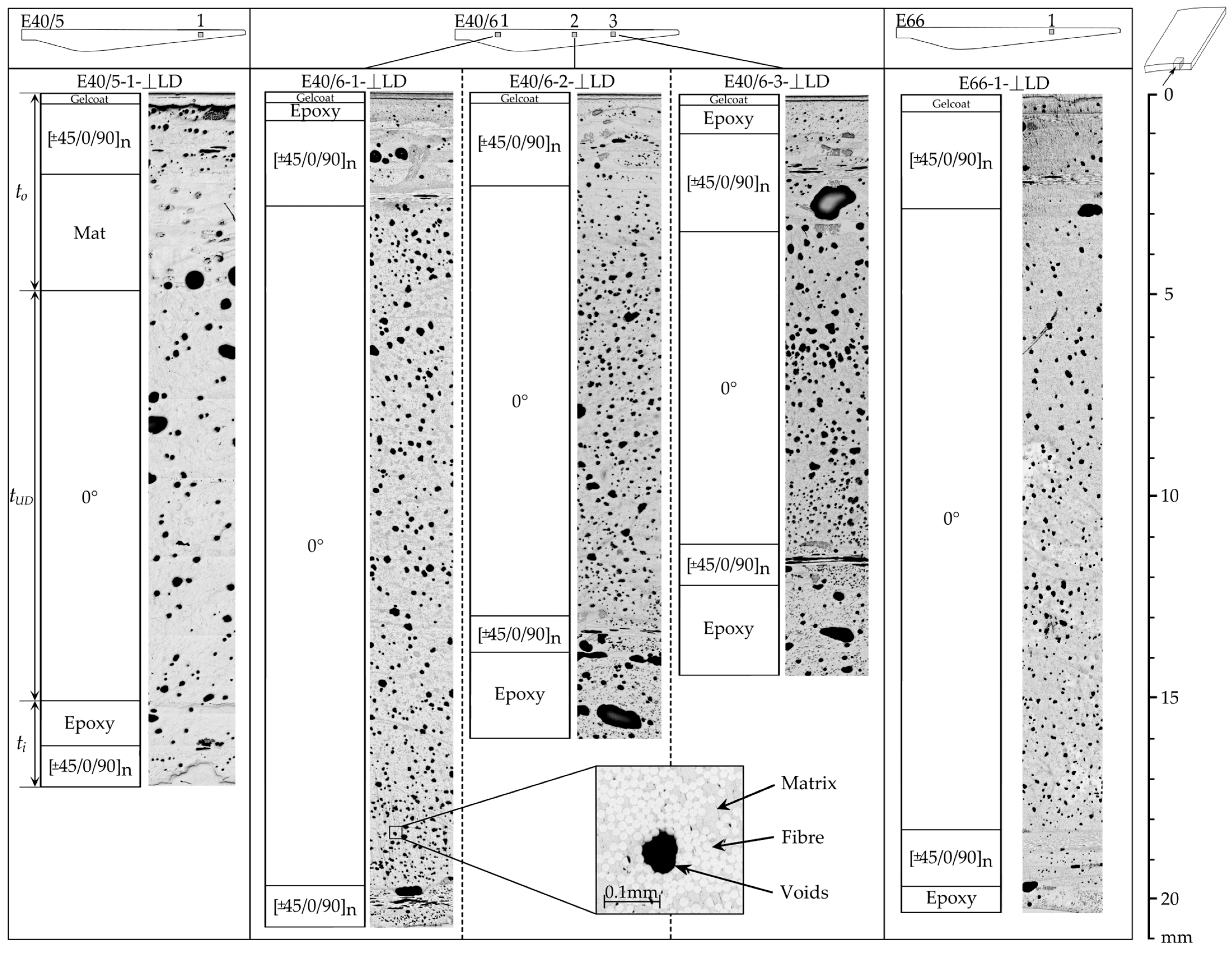
Figure 8 shows the microscopic images in cross sections perpendicular to LD, obtained from the three investigated WTB models as well as from different locations within the same E40/6 WTB.
The microscopic images exhibit notable variability in terms of their stacking sequence, fibre architecture, and void content. Nevertheless, a consistent structural pattern is observed across all micrographs: a UD fibre core, flanked by epoxy and multiaxial layers, with a gelcoat layer on the outer surface. This is highlighted in the E40/5 microscopic image with t o (outer non-UD region), t U D (UD region) and t i (inner non-UD region). The thicknesses and relative proportions of the composite layers vary across the spar cap specimens. This geometric variation is also observed within the WTBs by visual inspection of cross-sections after the initial TD cuts. In the E40/6 WTB, spar cap thickness decreases from over 20 mm at location 1 (E40/6-1-⟂LD) to approximately 16 mm at location 2 (E40/6-2-⟂LD) and below 15 mm at location 3 (E40/6-3-⟂LD), reflecting the distribution of aerodynamic bending moments along the WTB length. In addition, the proportion of the UD fibre region ( t U D ) decreases towards the tip. Variations in the thicknesses of the outer ( t o ) and inner epoxy and multiaxial layers ( t i ) contribute to geometric asymmetry in the cross-sections based on the location that is investigated.
For the E40/5 and E66 specimens, no operational damages are observed in the examined areas. The E40/5 specimens exhibit numerous large voids probably originating from manufacturing processes. In the E66 specimens they are smaller and more uniformly distributed. The void content V 0 in the E40/6 specimens is higher compared to the E66. Cross-sectional micrographs in the LD direction (Appendix B) indicate that these are predominantly tubular voids.
The main stacking sequence, along with the quantified void content, as optically determined in Figure 8, is outlined in Table 1.

3.1.2. Calcination

Table 2 summarises the calcination analysis results.
The fibre volume fraction V F of the E66 specimens is determined to be 54.2%. In contrast, the E40/5 specimens, representing an older WTB design with potentially lower manufacturing quality, exhibit a lower V F of 43.9%. This is reflected in the higher coefficient of variation, which was lowest for the E66 specimens (0.92%) and highest for the E40/5 specimens (4.33%), as well as in the higher void content V 0 observed in the E40/5 specimens. Slight variations in V F are observed along the length of the E40/6 WTB spar cap.

3.1.3. Tensile Tests

In Figure 9a, the representative stress–strain curves and points of failure for all LD specimens at RT from each of the investigated WTB models are shown (for the E40/6, the curve of a specimen from location 2 is plotted). All LD specimens exhibited linear elastic behaviour during tensile loading. The failure observed is characterised by (i) delamination at the interface between the UD fibre core and the non-UD outer epoxy and multiaxial layers, possibly caused by high interlaminar stresses and matrix cracks at the ply interface, followed immediately by (ii) tensile fibre failure. The TD specimens at RT (for the E40/6, the curve of a specimen from location 3 is plotted) show significantly lower mechanical performance (Figure 9b). The failure mode of all TD specimens was characterised by a transverse crack, oriented perpendicularly to the applied load.
The tensile results highlight the strong anisotropy of the spar cap specimens, which can be attributed to the largely UD nature of the spar cap beams. The large scatter for E40/5 LD specimens suggests a greater variability in terms of stiffness compared to E40/6 and E66. This is presumably attributable to a more irregular void distribution, resulting in a higher degree of material inconsistency, for instance in terms of V F .
Table 3 summarises the tensile test results—including as-received strength R r , modulus E r and strain at failure ε r —for the investigated EoL WTB spar cap specimens.
The E66 LD specimens exhibit significantly higher tensile strength and modulus than the E40/5, resulting from their higher fibre volume fraction V F . Furthermore, the elevated void content in the E40/5 spar cap material contributes to both greater variability and reduced tensile properties compared to the E66 spar cap material. The higher tensile properties of the E66 TD specimens, where matrix properties are more dominant, can also be attributed to their lower void content.
For the E40/6 LD specimens, both strength and modulus are slightly higher in specimens taken from location 2 compared to those extracted from location 1. This difference can be linked to a slightly higher V F in the E40/6 2 material. The greater variability in the E40/6 1 LD specimens may result from the higher void content near the root of the E40/6 WTB. Notably, the spar cap at the E40/6 1 location is thicker (20 mm) than at E40/6 2 (16 mm), which may influence void formation.
The COV for strength frequently exceeds 10%, which likely reflects the presence of defects in the spar cap material. This variability should be accounted for in the design process by applying appropriate safety factors.
For the E40/5 WTB spar cap material, the T g is determined to be approximately 100 °C. The T g values for the E40/6 and E66 spar cap materials are approximately 80 °C and 75 °C, respectively. According to the BÜV, these values are close to the temperature of 67 °C, indicating that the mechanical properties may be affected within this temperature range. This variation in T g should be considered during the design process for second-life applications involving repurposed GFRP beams.

3.1.4. Mechanical Characterisation of Spar Caps: A Comparison with Literature Data

The as-received material properties of the spar cap specimens investigated in this study are summarised in Table 4, supplemented with experimental data from the literature. For the E40/6 and DEBRA-25 models, material properties from different locations along the WTB were available. Therefore, mean values are shown. All listed spar caps are made of GFRP. The mechanical properties ( R r , E r , ε r ) were all obtained in tensile tests.
The as-received mechanical properties indicate that the spar cap material from different WTBs retains a significant proportion of its mechanical performance after the first service life. These findings suggest its potential for repurposing in both structural and non-structural second-life applications. The quasi-UD stacking sequence results in transversely isotropic behaviour, a factor which must be considered during the design phase of repurposing spar cap beams for second-life applications in the construction sector.
However, a significant variation in the as-received mechanical properties is observed across different EoL spar cap components. For example, tensile strength R r in LD ranges from approximately 342 MPa to 700 MPa, and tensile modulus E r in LD varies from approximately 15 GPa to 40 GPa. The following parameters are identified as having a significant impact on the variation in mechanical properties (addressing RQ2).
  • Composite architecture and spar cap thickness: The substantial differences between the outer region ( t o ) and inner region thicknesses ( t i ) of the epoxy and multiaxial layers can result in geometric asymmetry. This asymmetry can lead to uneven load distribution, reducing, e.g., stiffness during bending loads. The overall thickness t t , width t w , t o and t i of the spar cap beam can be measured using basic equipment, since the UD region can be visually distinguished from the non-UD region.
  • Fibre volume fraction V F : It is observed from Table 4 that longer WTBs exhibit a higher V F in the UD region of the spar cap, resulting in an increased strength and modulus in LD. The parameter V F can be determined by correlating the length of the WTB, as derived from the rotor diameter of the WT in the MaStR. The suggested range of V F is 36% and 56% for WTB lengths from 9.8 m to 37 m. In scenarios where a low uncertainty in the predicted properties is required, the value of V F can be determined through experimentation (e.g., calcination), thereby reducing prediction uncertainty.
  • Production quality: Unoptimised production quality is shown by a large number of defects in the spar cap material, which leads to reduced strain at failure, lower ultimate tensile strength and higher variance in V F .
  • Load history: No link was identified between service life and material properties. Nonetheless, severely damaged spar cap components should be identified by NDT and excluded from the repurposing streams.
  • Matrix type: The matrix of spar cap beams could influence the mechanical properties. Matrix materials that are sensitive to elevated temperatures may undergo degradation in properties, which have to be considered in the design process of applications using repurposed EoL spar cap beams.

3.2. Prediction Tool for Rapid Characterisation of As-Received Spar Cap Properties

The identified practically accessible parameters are assigned to macro-, meso-, and micro-scale (Table 5):
Following the quantification of the parameters for the description of the structure of the spar cap beam, the implementation of these parameters into the Excel-based prediction tool is undertaken. Utilising the fibre volume fraction V F at the microscale and implementing the rule of mixtures, the stiffness of the UD region can be homogenised (Figure 10).
The functionality of the prediction tool is demonstrated by calculating the flexural modulus of a tested E40/5 substructure spar cap beam, as described in Section 2.3.2. The macro-/meso-scale parameters are quantified using a calliper gauge, yielding the following measurements: t t = 33.23   m m ; t w = 32.35   m m ; t o = 4.71   m m and t i = 2   m m . Based on the calcination results, the fibre volume fraction V F is assumed to be 43.9%. For simplification, the t o and t i non-UD regions are assumed to consist exclusively of matrix material (epoxy resin).
Using this simplification, the modulus of the UD spar cap region is first obtained from V F and constituent moduli via the rule of mixtures. The flexural modulus of the section is then calculated analytically from the geometry and stiffness of the individual layers: the neutral axis is located from modulus–area weighting, the stiffness-weighted second moment of area is determined, and this is normalised by the geometric second moment of area. The detailed calculation steps are provided in Appendix C.
The predicted flexural modulus of the E40/5 spar cap material is 20.59 GPa, compared to an experimentally determined value of 21.84 GPa for the analysed beam (see Figure A3). The close agreement indicated that the prediction model captures the main stiffness characteristics. The slightly higher experimental value is likely due to the simplification of modelling the non-UD regions as consisting entirely of matrix material, a conservative assumption consistent with the intended purpose of the prediction tool. These results support the tool’s applicability for estimating the flexural stiffness of untested spar cap beams. This information is highly relevant for structural repurposing in the construction sector and directly addresses RQ3.

4. Discussion

The proposed framework (see the first objective, O1) effectively combines non-destructive testing (NDT) and material characterisation techniques to determine the key mechanical properties of spar cap components needed for second-life pathways. This integrated approach addresses the information gap between as-received mechanical properties and second-life application requirements.
The comparative analysis of spar caps from the E40/5, E40/6, and E66 WTB models (see the second objective, O2) indicates a correlation between WTB length, geometric structure, and mechanical performance. The E66, representing a more recent and longer WTB design, exhibits higher fibre volume fraction, lower void content, and improved tensile properties compared to the older E40/5 design. This underlines the relevance of manufacturing generation and WTB geometry as key determinants of as-received performance. Nonetheless, the specimen size and model selection in this study were limited, which may restrict the generalisability of the observed trends. Broader datasets covering a wider variety of manufacturers and production years are needed to confirm these relationships.
The prediction tool (see the third objective, O3) demonstrates that the identified practically accessible parameters can be successfully implemented as input for analytic calculations. The encouraging agreement between predicted and experimentally measured bending stiffness suggests that the approach can support decision-making within the framework. However, extending the tool’s capability to also estimate strength properties and validating it with additional mechanical tests would enhance its applicability and reliability for industry use. Furthermore, the approach relies on assumptions for key material parameters, which inherently introduces uncertainty. This issue could be mitigated by incorporating appropriate safety margins in the design of the new second-life application. The results from the experimental campaign also revealed a high coefficient of variation (COV), indicating significant scatter in the data. Therefore, a substantial overstrength should be considered in the design, as several factors affecting the mechanical properties during the WTB’s first service life cannot be fully accounted for. In the context of the construction sector, it is also important to understand the material behaviour at 67 °C for second-life applications where elevated temperatures are expected, as the variety of matrix systems and compositions results in different glass transition temperatures.
Considering this, future work should aim to reduce parameter uncertainty without relying on extensive and expensive testing. This includes, on the one hand, collecting more experimental data on specific WTB models and lengths to refine micro-scale parameter estimates. On the other hand, the robustness and objectivity of parameter determination at the macro- and meso-scales should be improved through data-driven methodologies, such as machine learning (ML). For example, thickness measurements taken on-site are prone to subjective error. By employing ML-based methods, such as image-based analysis from photographs captured in the field, macro- and meso-scale parameters can be determined in a more repeatable and consistent manner.
From a strategic perspective, this study also highlights the need for a change in the design of applications using repurposed spar cap components. The conventional product design in the construction sector often assumes precise control over material form and geometry. However, in a circular context, applications must adapt to the inherent variability of reclaimed materials. The concept of “form follows availability” is crucial: accepting the as-received geometry of EoL spar caps enables reduced processing, preserves material integrity, and allows for energy-efficient repurposing at scale. Practical design strategies already exist that demonstrate the viability of this approach. This has been achieved through the utilisation of flexible and modular design principles. This concept aligns with the broader concept of “Design for Circularity”, where composite components could be designed with their second-life already in mind. Digital Product Passports (DPPs) or similar material labelling systems could provide essential data—such as geometry, material composition, and performance characteristics—at the EoL, thus enabling more targeted and efficient repurposing.

5. Conclusions

This study presents a framework to enable the structural repurposing of spar cap beams from end-of-life (EoL) wind turbine blades (WTBs), targeting applications in the construction sector.
Focusing on the spar cap component as a substructure of EoL WTBs, the high variability among WTBs in terms of geometry and material composition is addressed, which presents a challenge to scaling up repurposing strategies. The extraction of semi-finished beams that can be cut in a standardised manner from different WTB models is proposed. These beams, even at the EoL stage, retain favourable as-received mechanical properties, thereby supporting repurposing strategies. The outlined prediction tool, based on the identified practically accessible parameters and analytic methods, is designed to support rapid on-site assessment, enabling efficient classification and assignment of materials to appropriate second-life material streams.
The overall goal of repurposing spar cap beams not only extends the service life of EoL composite materials from WTBs but also advances their circular use by preserving structural integrity across applications. In the construction sector, these lightweight composite elements can substitute virgin materials, potentially reducing costs if automated cutting processes are established. This contributes to a decrease in CO2 emissions by avoiding the production of virgin materials and therefore supports broader sustainability objectives within the construction industry.

Author Contributions

Conceptualisation, P.J., M.B. and A.A.; methodology, P.J., M.B. and A.A.; software, P.J. and M.B.; validation, P.J. and M.B.; formal analysis, P.J. and M.B.; investigation, P.J.; resources, P.J.; data curation, P.J. and M.B.; writing—original draft preparation, P.J.; writing—review and editing, M.B., A.A., R.K., R.P. and R.B.; visualisation, P.J. and M.B.; supervision, A.A., R.K. and R.B.; project administration, N.M. and R.B.; funding acquisition, R.B. All authors have read and agreed to the published version of the manuscript.

Funding

The study has been performed within the HORIZON-CL4-2021-RESILIENCE-01 project “European recycling and circularity in large composite components (EuReComp),” called “A Digitized, Resource-Efficient and Resilient Industry 2021,” HORIZON Research and Innovation Actions, Contract Number 101058089. Views and opinions expressed are those of the authors only and do not necessarily reflect those of the European Union or HADEA. Neither the European Union nor HADEA can be held responsible for them.

Institutional Review Board Statement

Not applicable.

Informed Consent Statement

Not applicable.

Data Availability Statement

The raw data of this article will be made available by the authors on request.

Acknowledgments

We would like to express our gratitude to Benjamin Pfeiffer for his technical assistance in determining the fibre mass and volume fractions, as well as for his assistance in preparing the tensile test specimens. We would like to thank Jannick Schneider for his assistance in preparing the micrograph specimens and Dimitrij Seibert for preparing the bending specimens. Elke Genzel was always available to respond to queries regarding the BÜV guideline, for which gratitude is extended. In addition, gratitude is extended to Enercon for the provision of the E40/6 WTB, which was instrumental in conducting material investigations. Finally, thanks to the Institute of Science and Innovation in Mechanical and Industrial Engineering (INEGI) for providing the E66 WTB spar cap materials used for specimen preparation. During the preparation of this study, the author(s) used ChatGPT 4.0 in order to improve readability, grammar and language. The authors have reviewed and edited the output and take full responsibility for the content of this publication. We would like to thank the anonymous reviewers, who obviously are experts with extensive knowledge and experience in this area, for their constructive comments, valuable insights and helpful suggestions, which have helped us to improve the quality of this work from its original manuscript.

Conflicts of Interest

The authors declare that the research was conducted in the absence of any commercial or financial relationships that could be construed as potential conflicts of interest.

Abbreviations

CFRPCarbon fibre reinforced polymer
DSCDifferential scanning calorimetry
DTDestructive testing
GFRPGlass fibre reinforced polymer
EoLEnd-of-life (as a WTB)
FRPFibre reinforced polymer
LDLongitudinal direction
MaStRMarktstammdatenregister
NDTNon-destructive testing
TDTransverse direction
WTWind turbine
WTBWind turbine blade
UDUnidirectional

Appendix A. The 67 °C Temperature Coming from the BÜV

According to the BÜV [27], the behaviour at the assumed maximum operating temperatures in the second-life is decisive for the material properties to be verified. This is derived from DIN EN 1991-1-5 (Einwirkung auf Tragwerke—Teil 1-5: Allgemeine Einwirkungen—Temperatureinwirkungen) [43] as well as the National Annex DIN EN 1991 1 5/NA. For use above ground, a maximum temperature must be determined depending on the surface of the structure. In the case of a light coloured or light-shining surface with a surface influence value of T s = 30   ° C and the maximum outside air temperature T m a x , the maximum outside temperature T o u t can be calculated:
T o u t = T m a x + T S
The assumed maximum outdoor temperature T m a x is defined for Germany in the National Annex of DIN EN 1991-1-5/NA as T m a x = 37   ° C . This results in the maximum outdoor temperature T o u t = 67   ° C .

Appendix B. Microscopic Images in LD

Figure A1. Spar cap specimen microscopic images in cross-section in LD.
Sustainability 17 07783 g0a1

Appendix C. Analytic Prediction

  • Geometry and layer set-up (rectangular cross section):
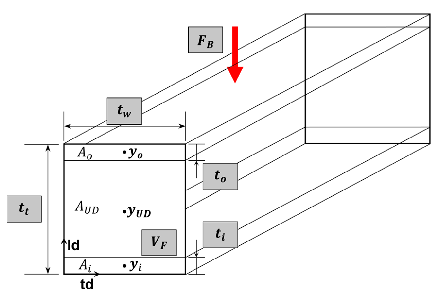
Total thickness: t t
Total width: t w
Outer (compression-side) thickness: t o
Inner (tension-side) thickness: t i
UD spar cap thickness: t U D = t t t o t i
Fibre volume fraction (UD region): V F
Figure A2. Parameters of the prediction tool highlighted (the red arrow F B represents the bending load).
Sustainability 17 07783 g0a2
Layer areas (assuming constant width t w ):
A o = t w t o ;   A U D = t w t U D ;   A i = t w t i
The centroid coordinate positions y o , y U D , y i follow directly from layer stacking starting at the inner layer, e.g., y i = t i 2 ;   y U D = t i + t U D 2 , y o = t i + t U D + t o 2 .
(1.)
Homogenised modulus of the UD layer (rule of mixtures)
E C = E F V F + E M ( 1 V F )
Converts the UD spar cap to an equivalent single phase with modulus E C from fibre modulus E F and matrix modulus E M using the specified fibre volume fraction V F .
(2.)
E-weighted neutral axis
y N A = E k A k y k E k A k    
w i t h   E k , A k , y k   { E M , A o , y o ; E C , A U D , y U D ; E M , A i , y I }
Locates the neutral axis of the transformed (E-weighted) section across the three layers (outer non-UD region, UD-region, inner non-UD region).
(3.)
E-weighted second moment of area
I e f f = E k ( I k + A k ( y k y N A ) 2 )
Computes the effective bending stiffness of the layered section using the transformed-section method (parallel axis term included). For rectangular layers:
I k =   t w t k 3 12     w i t h   t k { t o ,   t U D ,   t i }
(4.)
Geometric second moment of area of the whole section
I g e o m = t w t t 3 12  
Reference (unweighted) second moment of area for a full rectangular section of width t w and thickness t t .
(5.)
Effective flexural modulus E r f
E r f = I e f f I g e o m  
Calculates the effective (section-level) flexural modulus from the E-weighted stiffness and the geometric spar cap reference.
Figure A3. Experimental flexural modulus.
Sustainability 17 07783 g0a3

References

  1. Liu, P.; Barlow, C.Y. Wind turbine blade waste in 2050. Waste Manag. 2017, 62, 229–240. [Google Scholar] [CrossRef] [PubMed]
  2. Mishnaevsky, L.; Branner, K.; Petersen, H.N.; Beauson, J.; McGugan, M.; Sørensen, B.F. Materials for Wind Turbine Blades: An Overview. Materials 2017, 10, 1285. [Google Scholar] [CrossRef]
  3. Spini, F.; Bettini, P. End-of-Life wind turbine blades: Review on recycling strategies. Compos. Part B Eng. 2024, 275, 111290. [Google Scholar] [CrossRef]
  4. Katnam, K.B.; Comer, A.J.; Roy, D.; Da Silva, L.F.M.; Young, T.M. Composite Repair in Wind Turbine Blades: An Overview. J. Adhes. 2015, 91, 113–139. [Google Scholar] [CrossRef]
  5. Overcash, M.; Twomey, J.; Asmatulu, E.; Vozzola, E.; Griffing, E. Thermoset composite recycling—Driving forces, development, and evolution of new opportunities. J. Compos. Mater. 2018, 52, 1033–1043. [Google Scholar] [CrossRef]
  6. Beauson, J.; Brøndsted, P. Wind Turbine Blades: An End of Life Perspective. In MARE-WINT; Ostachowicz, W., McGugan, M., Schröder-Hinrichs, J.-U., Luczak, M., Eds.; Springer International Publishing: Cham, Switzerland, 2016; pp. 421–432. ISBN 978-3-319-39094-9. [Google Scholar]
  7. Lund, K.W.; Madsen, E.S. State-of-the-art value chain roadmap for sustainable end-of-life wind turbine blades. Renew. Sustain. Energy Rev. 2024, 192, 114234. [Google Scholar] [CrossRef]
  8. Mamanpush, S.H.; Li, H.; Englund, K.; Tabatabaei, A.T. Recycled wind turbine blades as a feedstock for second generation composites. Waste Manag. 2018, 76, 708–714. [Google Scholar] [CrossRef]
  9. Germanischer Lloyd. Rules and Guidelines Industrial Services: Guideline for the Certification of Offshore Wind Turbines; Germanischer Lloyd: Hamburg, Germany, 2010. [Google Scholar]
  10. Lahuerta, F.; Gesto, D.; Prieto, C.; Johst, P.; Kucher, M.; Mozas, E.; Gracia, O.; Böhm, R.; Bielsa, J.M. Decommissioning Inventory for Wind Turbine Blades Installed Until 2022 in Europe. Mater. Circ. Econ. 2023, 5, 16. [Google Scholar] [CrossRef]
  11. Potting, J.; Hekkert, M.; Worrell, E.; and Hanemaaijer, A. Circular Economy: Measuring Innovation in the Product Chain. Available online: https://www.pbl.nl/sites/default/files/downloads/pbl-2016-circular-economy-measuring-innovation-in-product-chains-2544.pdf (accessed on 25 January 2023).
  12. Kupfer, R.; Schilling, L.; Spitzer, S.; Zichner, M.; Gude, M. Neutral lightweight engineering: A holistic approach towards sustainability driven engineering. Discov. Sustain. 2022, 3, 17. [Google Scholar] [CrossRef]
  13. Deeney, P.; Nagle, A.J.; Gough, F.; Lemmertz, H.; Delaney, E.L.; McKinley, J.M.; Graham, C.; Leahy, P.G.; Dunphy, N.P.; Mullally, G. End-of-Life alternatives for wind turbine blades: Sustainability Indices based on the UN sustainable development goals. Resour. Conserv. Recycl. 2021, 171, 105642. [Google Scholar] [CrossRef]
  14. Johst, P.; Kucher, M.; Schulz, P.; Knorr, A.; Kupfer, R.; Böhm, R. Identification of circular eco-subsystems for end-of-life aviation composite components based on a systematized R6-strategy. J. Phys. Conf. Ser. 2023, 2526, 12055. [Google Scholar] [CrossRef]
  15. Joustra, J.; Flipsen, B.; Balkenende, R. Structural reuse of high end composite products: A design case study on wind turbine blades. Resour. Conserv. Recycl. 2021, 167, 105393. [Google Scholar] [CrossRef]
  16. Ellen MacArthur Foundation. Towards the Circular Economy: Economic and Business Rationale for an Accelerated Transition. Available online: https://emf.thirdlight.com/file/24/xTyQj3oxiYNMO1xTFs9xT5LF3C/Towards%20the%20circular%20economy%20Vol%201%3A%20an%20economic%20and%20business%20rationale%20for%20an%20accelerated%20transition.pdf (accessed on 20 February 2023).
  17. André, A.; Juntikka, M.; Mattsson, C.; Hammar, T.; Haghani, R. Sustainable repurpose of end-of-life fiber reinforced polymer composites: A new circular pedestrian bridge concept. J. Environ. Manag. 2024, 367, 122015. [Google Scholar] [CrossRef] [PubMed]
  18. Bank, L.; Arias, F.; Yazdanbakhsh, A.; Gentry, T.; Al-Haddad, T.; Chen, J.-F.; Morrow, R. Concepts for Reusing Composite Materials from Decommissioned Wind Turbine Blades in Affordable Housing. Recycling 2018, 3, 3. [Google Scholar] [CrossRef]
  19. Alshannaq, A.A.; Respert, J.A.; Henao, Y.; Bank, L.C.; Gentry, T.R. Experimental Testing and Numerical Analysis of a GFRP BladePole Prototype Repurposed from a Decommissioned GE37 Wind Turbine Blade. J. Compos. Constr. 2025, 29, 04024079. [Google Scholar] [CrossRef]
  20. André, A.; Bru, T.; Abbasi, A.G.; Sinha, S.; Nunes, S.; Juntikka, M.; Kazmierczak, K.; Egilsson, N.Ó.; Frid, G.; Sobczyk, M.; et al. A Holistic and Circular Approach for Managing End-of-Service Wind Turbine Blades. Sustainability 2024, 16, 7858. [Google Scholar] [CrossRef]
  21. Beauson, J.; Laurent, A.; Rudolph, D.P.; Pagh Jensen, J. The complex end-of-life of wind turbine blades: A review of the European context. Renew. Sustain. Energy Rev. 2022, 155, 111847. [Google Scholar] [CrossRef]
  22. MaStR. Aktuelle Einheitenübersicht/Current Unit Overview. Available online: https://www.marktstammdatenregister.de/MaStR/Einheit/Einheiten/OeffentlicheEinheitenuebersicht (accessed on 15 May 2025).
  23. Alshannaq, A.A.; Respert, J.A.; Bank, L.C.; Scott, D.W.; Gentry, T.R. As-Received Physical and Mechanical Properties of the Spar Cap of a GE37 Decommissioned Glass FRP Wind Turbine Blade. J. Mater. Civ. Eng. 2022, 34, 04022266. [Google Scholar] [CrossRef]
  24. Ruane, K.; Zhang, Z.; Nagle, A.; Huynh, A.; Alshannaq, A.; McDonald, A.; Leahy, P.; Soutsos, M.; McKinley, J.; Gentry, R.; et al. Material and Structural Characterization of a Wind Turbine Blade for Use as a Bridge Girder. Transp. Res. Rec. 2022, 2676, 354–362. [Google Scholar] [CrossRef]
  25. Joustra, J.; Flipsen, B.; Balkenende, R. Structural reuse of wind turbine blades through segmentation. Compos. Part C Open Access 2021, 5, 100137. [Google Scholar] [CrossRef]
  26. Ennis, B.L.; Kelley, C.L.; Naughton, B.T. Optimized Carbon Fiber Composites in Wind Turbine Blade Design. SANDIA REPORT SAND2019-14173. 2019. Available online: https://www.energy.gov/sites/prod/files/2019/12/f69/SAND2019-14173-Optimized.pdf (accessed on 10 June 2025).
  27. Ackermann, G.; Deußer, S.; Gabler, S.; Gastmeyer, R.; Genzel, E.; Gerold, M.; Jung, C.; Knippers, J.; Krahwinkel, M.; Kruppe, J.; et al. BÜV-Empfehlung: Tragende Kunststoffbauteile im Bauwesen [TKB]: Entwurf, Bemessung und Konstruktion. Available online: https://new.bauueberwachungsverein.de/themes/buev/assets/files/Kunststoff_Empf.pdf (accessed on 10 June 2025).
  28. Jensen, J.P.; Skelton, K. Wind turbine blade recycling: Experiences, challenges and possibilities in a circular economy. Renew. Sustain. Energy Rev. 2018, 97, 165–176. [Google Scholar] [CrossRef]
  29. Johst, P.; Bühl, M.; Enderle, C.; Kupfer, R.; Modler, N.; Böhm, R. Forecasting wind turbine blade waste with material composition and geographical distribution: Methodology and application to Germany. Resour. Conserv. Recycl. 2024, 211, 107876. [Google Scholar] [CrossRef]
  30. Rahimizadeh, A.; Kalman, J.; Fayazbakhsh, K.; Lessard, L. Mechanical and thermal study of 3D printing composite filaments from wind turbine waste. Polym. Compos. 2021, 42, 2305–2316. [Google Scholar] [CrossRef]
  31. Zhang, Y.; Cui, S.; Wang, X.; Yang, B.; Zhang, N.; Liu, T. Microstructure and performance of recycled wind turbine blade based 3D printed concrete. Clean. Waste Syst. 2025, 10, 100206. [Google Scholar] [CrossRef]
  32. Carrete, I.A.; Joustra, J.J.; Balkenende, A.R. Circular applications through selection strategies (CATSS): A methodology for identifying reuse applications for end-of-life wind turbine blades. IOP Conf. Ser. Mater. Sci. Eng. 2023, 1293, 12011. [Google Scholar] [CrossRef]
  33. DIN EN ISO 1172; Textile-Glass-Reinforced Plastics—Prepregs, Moulding Compounds and Laminates—Determination of the Textile-Glass and Mineral-Filler Content Using Calcination Methods. Deutsches Institut für Normung e. V.: Berlin, Germany, 2023.
  34. DIN EN ISO 1183-1; Plastics-Methods for Determining the Density of Non-Cellular Plastics—Part 1: Immersion Method, Liquid Pycnometer Method and Titration Method. Deutsches Institut für Normung e. V.: Berlin, Germany, 2019.
  35. Specification—Technical Data and Equipment List: Enercon E-40/6.44/E2/E40-6. Available online: https://en.wind-turbine.com/cms/storage/uploads/2022/08/09/01_specificationenercone40644e244884_uid_62f18c8a4d259.pdf (accessed on 25 April 2025).
  36. DIN EN ISO 527-5; Plastics—Determination of Tensile Properties—Part 5: Test Conditions for Unidirectional Fibre-Reinforced Plastic Composites. Deutsches Institut für Normung e. V.: Berlin, Germany, 2022.
  37. DIN EN ISO 11357-1; Plastics—Differentail Scanning Calorimetry (DSC)—Part 1: General Principles. Deutsches Institut für Normung e. V.: Berlin, Germany, 2023.
  38. DIN EN ISO 14125; Fibre-Reinforced Plastic Composites—Determination of Flexural Properties. Deutsches Institut für Normung e. V.: Berlin, Germany, 2011.
  39. Rubiella, C.; Hessabi, C.A.; Fallah, A.S. State of the art in fatigue modelling of composite wind turbine blades. Int. J. Fatigue 2018, 117, 230–245. [Google Scholar] [CrossRef]
  40. Schürmann, H. Konstruieren mit Faser-Kunststoff-Verbunden: Mit 39 Tabellen; 2., bearb. und erw. Aufl.; Springer: Berlin/Heidelberg, Germany, 2007; ISBN 978-3-540-72189-5. [Google Scholar]
  41. Sayer, F.; Bürkner, F.; Buchholz, B.; Strobel, M.; van Wingerde, A.M.; Busmann, H.-G.; Seifert, H. Influence of a wind turbine service life on the mechanical properties of the material and the blade. Wind Energy 2013, 16, 163–174. [Google Scholar] [CrossRef]
  42. Ahmed, M.M.Z.; Alzahrani, B.; Jouini, N.; Hessien, M.M.; Ataya, S. The Role of Orientation and Temperature on the Mechanical Properties of a 20 Years Old Wind Turbine Blade GFR Composite. Polymers 2021, 13, 1144. [Google Scholar] [CrossRef] [PubMed]
  43. DIN EN 1991-1-5; Eurocode 1: Einwirkungen auf Tragwerke—Teil 1-5: Allgemeine Einwirkungen—Temperatureinwirkungen; Deutsche Fassung. Deutsches Institut für Normung e. V.: Berlin, Germany, 2010.
Figure 1. Sectioning approach for obtaining continuous components from the EoL WTB material stream (a) TD cuts; (b) LD cuts; (c) semi-finished products (* as cut spar cap beams); and (d) repurposed EoL WTB components in second-life applications within the construction sector (* as repurposed spar cap beams).
Sustainability 17 07783 g001
Figure 2. EoL WTB segments from (a) E40/5 WTB, (b) E40/6 WTB and (c) E66 WTB.
Sustainability 17 07783 g002
Figure 3. Framework showing: (a) different material streams; (b) material stream assignment; and (c) material characterisation.
Sustainability 17 07783 g003
Figure 4. Cutting process of the EoL E40 WTB with (a) TD cuts (dotted lines), (b) LD cuts (dotted lines) and (c) NDT of spar cap beams, (d) tensile test specimen preparation.
Sustainability 17 07783 g004
Figure 5. (a) Locations for microstructure analysis: (b) perpendicular to LD; (c) in LD.
Sustainability 17 07783 g005
Figure 6. Dimensions of tensile specimens and testing rig.
Sustainability 17 07783 g006
Figure 7. (a) Bending testing rig with E40/5 spar cap beam, (b) cross-section of E40/5 spar cap beam.
Sustainability 17 07783 g007
Figure 8. Spar cap specimen microscopic images in cross-section perpendicular to LD.
Sustainability 17 07783 g008
Figure 9. (a) Stress–strain curves incl. failure points of LD specimens; (b) Stress–strain curves incl. failure points of TD specimens for the investigated WTB models at RT.
Sustainability 17 07783 g009
Figure 10. Parametrised prediction tool for estimation of as-received spar cap properties.
Sustainability 17 07783 g010
Table 1. Void content and stacking sequence from E40/5, E40/6 and E66 WTB spar cap specimens.
Location V 0 Spar Cap
Thickness
UD   Thickness   ( Portion )   t U D Multiaxial ThicknessEpo/Mat/Gel Thickness
%mmmm (%)mm (%)mm (%)
E40/5 WTB
Sustainability 17 07783 i0016.917.210.3 (60%)2.8 (16%)4.1 (24%)
E40/6 WTB
Sustainability 17 07783 i0026.820.817.8 (86%)2.3 (11%)0.7 (3%)
Sustainability 17 07783 i0037.516.010.7 (67%)3.1 (19%)2.2 (14%)
Sustainability 17 07783 i00412.014.67.8 (53%)3.7 (26%)3.1 (21%)
E66 WTB
Sustainability 17 07783 i0054.820.415.4 (75%)4.2 (21%)0.8 (4%)
Table 2. Mass and volume fractions of the spar cap specimens from different WTB models.
LocationNMm (%)MF (%)Vm (%)VF (%)/COV
E40/5 WTB
Sustainability 17 07783 i006535.065.049.343.9/4.33
E40/6 WTB
Sustainability 17 07783 i007626.673.441.354.7/3.11
Sustainability 17 07783 i008425.474.640.356.6/3.0
Sustainability 17 07783 i009424.275.838.357.6/1.91
Average 25.474.640.056.3/2.67
E66 WTB
Sustainability 17 07783 i010527.672.443.054.2/0.92
N = Number of specimens; Mm = Resin mass fraction; MF = Fibre mass fraction; Vm = Matrix volume fraction; VF = Fibre volume fraction; COV = Coefficient of variation (%).
Table 3. Tensile test results of E40/5, E40/6 and E66 WTB spar cap specimens.
LocationDirectionN * Strength   R r Modulus   E r Strain   at   Failure   ε r
Mean (MPa)COV *Mean (GPa)COV *Mean (%)COV *
E40/5 WTB
Sustainability 17 07783 i011LD24478.498.4330.717.91.7011.59
TD1617.3912.886.929.220.2410.34
E40/6 WTB
Sustainability 17 07783 i012LD5496.911.7238.562.131.4312.82
TD814.7014.328.2510.390.1712.05
Sustainability 17 07783 i013LD7566.614.9640.321.581.55.52
Sustainability 17 07783 i014TD1416.7711.1812.317.650.1313.66
E66 WTB
Sustainability 17 07783 i015LD15698.789.9637.452.642.0711.4
TD934.475.7510.342.060.349.06
* N = number of specimens; COV = coefficient of variation (%).
Table 4. Comparison of as-received properties of E40/5, E40/6 and E66 with literature data.
WTB Model/
Length
HistoryVF (%) Strength   R r (MPa) Modulus   E r (GPa) Strain   ε r (%)
Void DensityService Life
(Years)
R r , L D , 23 R r , T D , 23 E r , L D , 23 E r , T D , 23 ε r , L D , 23 ε r , T D , 23
This studyE40/5/
19.3 m
High2043.9 *478.4917.6330.716.871.70.25
E40/6/
21 m
High056.3 *531.7616.0139.4410.831.470.14
E66/
33 m
Low2054.2 *698.7834.4737.4510.342.070.34
Data in the literatureGE 37/
37 mm [23]
Assumed to be low1148–5059733.636.810.71.940.29
DEBRA-25/
11.6 m [41]
Not specified18-470.1-25.97-1.87-
100 kW WT/
9.8 m [42]
High20 (unidentified)38–40 **3507015.67.41.750.95
LM 13.4/
13.4 m [24]
Not specified2736–433421627.5---
* Only UD fibre region, ** M F = 55–60.
Table 5. Assignment of parameters to the macro-, meso-, and micro-scales.
ScaleParameter
Macro/Meso t t as overall spar cap thickness
t w as overall spar cap width
t O as outer non-UD region thickness
t i as inner non-UD region thickness
Micro V F representing the fibre volume fraction of the UD region
Disclaimer/Publisher’s Note: The statements, opinions and data contained in all publications are solely those of the individual author(s) and contributor(s) and not of MDPI and/or the editor(s). MDPI and/or the editor(s) disclaim responsibility for any injury to people or property resulting from any ideas, methods, instructions or products referred to in the content.