Article

Self-Healing Asphalt Mixtures Meso-Modelling: Impact of Capsule Content on Stiffness and Tensile Strength

1
LNEC—National Laboratory for Civil Engineering, 1700-066 Lisbon, Portugal
2
CERIS, Department of Civil Engineering, NOVA School of Science and Technology, Universidade NOVA de Lisboa, 2829-516 Caparica, Portugal
*
Author to whom correspondence should be addressed.
Sustainability 2025, 17(16), 7502; https://doi.org/10.3390/su17167502
Submission received: 2 May 2025 / Revised: 12 June 2025 / Accepted: 8 August 2025 / Published: 19 August 2025
(This article belongs to the Section Sustainable Materials)

Abstract

Capsule-based self-healing technologies offer a promising solution to extend pavement service life without requiring external activation. The effect of the capsule content on the mechanical behaviour of self-healing asphalt mixtures still needs to be understood. This study presents a numerical evaluation of the isolated effect of incorporating capsules containing encapsulated rejuvenators, at different volume contents, on the stiffness and strength of asphalt mixtures through a three-dimensional discrete-based programme (VirtualPM3DLab), which has been shown to predict well the experimental behaviour of asphalt mixtures. Uniaxial tension–compression cyclic and monotonic tensile tests on notched specimens are carried out for three capsule contents commonly adopted in experimental investigations (0.30, 0.75, and 1.25 wt.%). The results show that the effect on the stiffness modulus progressively increases as the capsule content grows in the asphalt mixture, with a reduction ranging from 4.3% to 12.3%. At the same time, the phase angle is marginally affected. The capsule continuum equivalent Young’s modulus has minimum influence on the overall rheological response, suggesting that the most critical parameter affecting asphalt mixture stiffness is the capsule content. Finally, while the peak tensile strength shows a maximum reduction of 12.4% at the highest capsule content, the stress–strain behaviour and damage evolution of the specimens remain largely unaffected. Most damaged contacts, which mainly include aggregate–mastic and mastic–mastic contacts, are highly localised around the notch tips. Contacts involving capsules remained intact during early and intermediate loading stages and only fractured during the final damage stage, suggesting a delayed activation consistent with the design of healing systems. The findings suggest that capsules within the studied contents may have a moderate impact on the mechanical properties of asphalt mixtures, especially for high-volume contents. For this reason, contents higher than 0.75 wt.% should be applied with caution.

1. Introduction

Asphalt mixtures are widely used for road surfacing due to their positive performance under traffic loads, low traffic noise, and high skid resistance. Despite their advantages and a potential service life of several decades, these materials are prone to deterioration, leading to negative environmental, economic, and maintenance impacts. Such impacts not only lead to increased greenhouse gas emissions due to frequent interventions and material production, but also contribute to the unsustainable use of resources and higher long-term infrastructure costs. This damage, typically cracking associated with the stiffening and brittleness of the aged binder [1,2], occurs despite the intrinsic self-healing capacity of asphalt mixtures [3].
To reduce these impacts and enhance sustainability, capsule-based self-healing technologies offer a promising solution, extending pavement service life without requiring external activation [4,5,6,7]. In the capsule–asphalt mixture method, capsules containing low-viscosity rejuvenators are embedded during fabrication [8]. These capsules remain intact during early use and break when cracks develop, releasing a rejuvenator that reduces the viscosity of the aged binder and enables it to flow into micro-cracks via capillary action [9]. This approach supports the development of cost-effective, durable, and environmentally sustainable road materials, representing a shift towards low-carbon infrastructure.
Experimental studies have indicated that capsules enhance the self-healing performance of asphalt mixtures without compromising their overall mechanical behaviour [10,11]. Nonetheless, encapsulated rejuvenators may influence the mechanical properties of mixtures [7,12,13]. Ozdaemir et al. [14] evaluated the effects of capsules on the mechanical properties of asphalt mixtures, showing that as the capsule content increases from 0.25 to 1.00 wt.%, the stiffness and resistance to permanent deformation gradually decrease. Aguirre et al. [15] used three-point bending tests to calculate the stiffness for three conditions (undamaged, damaged, and healed) under different temperature conditions. Other factors that may affect the mechanical behaviour of asphalt mixtures include capsule breakage, premature rejuvenator release, the localised softening effect of the released rejuvenator, capsule low mechanical strength, and capsule size, which may influence the overall durability and performance of the pavement [16,17,18,19].
Despite these advances, the full effect of capsules on the mechanical properties of asphalt mixtures remains insufficiently understood. Most analyses are experimental, facing challenges in (a) defining interactions among different materials, (b) isolating the effect of specific conditions, such as the number of broken capsules, and (c) assessing the actual effects of capsules on stiffness and tensile strength of asphalt mixtures without considering the effect of the rejuvenator. For example, laboratory tests show that the initial stiffness of asphalt mixtures (undamaged) is lower than that of specimens without capsules [20]. Following experimental investigations to understand these factors is challenging. Numerical modelling may provide valuable insights into these concerns, particularly regarding the impact of capsules on the stiffness modulus and tensile strength of asphalt mixtures before the rejuvenator is activated, thereby guiding capsule performance.
Numerical modelling, particularly through the Discrete Element Method (DEM), offers an effective way to overcome the limitations of laboratory testing. The DEM has been widely adopted by pavement researchers to model the heterogeneous nature of asphalt mixtures and easily simulate large deformations and fractures in these materials [21,22,23,24,25]. Recently, numerical studies on the effect of rejuvenators and capsules on asphalt materials have gained attention [26,27]. Zhang et al. [28] investigated crack resistance and design properties of microcapsules in asphalt pavement, showing that capsules can be modelled as elastic and have no significant effect on the elastic constants of asphalt mixtures. Through uniaxial tensile numerical tests, Ding et al. [9] verified the effects of capsule content, wall modulus, and wall thickness of microcapsules on the mechanical behaviour of asphalt pavements. Zhang et al. [29] assessed the mechanical behaviour of microcapsules to improve their survival rate, achieving a minimum survival rate of 70%.
Even though significant progress has been made in recent years in modelling asphalt mixtures, further improvements are needed, e.g., most studies still adopt simplified contact models and two-dimensional approaches [30,31,32,33]. In addition, few studies have been conducted at a meso-scale to evaluate self-healing asphalt mixtures incorporating capsules. Even though it is assumed that the effect of capsules is more pronounced once the rejuvenator is released, a more detailed meso-scale assessment is necessary to evaluate the performance of capsules before rejuvenator activation, especially because they may influence the mixture modulus even without releasing the rejuvenator [34].

2. Objectives

In line with the Green Deal goal of transforming Europe into a modern, digital, resource-efficient, climate-neutral, and competitive economy, this research aims to develop a virtual laboratory for asphalt materials—VirtualPM3DLab—to assist in road design and the evaluation of self-repair techniques that may help reduce maintenance needs and extend service life.
This paper investigates the effect of capsules on the mechanical performance of undamaged asphalt mixtures through DEM–based numerical simulations, aiming to contribute to the development of more durable and sustainable pavement solutions by identifying critical thresholds of capsule incorporation. Two aspects are analysed: (a) the effect on stiffness properties and the influence of capsule continuum equivalent Young’s modulus, based on dynamic tests, and (b) the effect on tensile strength, based on monotonic tests. In the rheological analysis, tension–compression simulations are conducted with loading frequencies ranging from 2 to 20 Hz. In the tensile strength analysis, numerical tensile tests are performed with a constant applied velocity of 1 × 10 4 m/s. In both assessments, capsules are randomly distributed throughout the asphalt mixtures and vary in size. The numerical evaluations consider different capsule contents introduced into the particle models, with values ranging from 0% (control specimen) to 1.25% of the total mass of the asphalt mixture. The numerical studies use the DEM-based VirtualPM3DLab software, adopting the calibrated parameters derived from previous studies [35,36]. In addition, these analyses focus on the isolated effect of capsule incorporation, without considering the combined influence of rejuvenator release due to cracking. In the adopted DEM model for asphalt mixtures, both the aggregates and the mastic are explicitly represented. Compared to other DEM approaches that employ a finer discretisation of the material’s internal structure [37,38,39,40,41], the proposed methodology offers a significantly lower computational cost.

3. 3D DEM Model of Asphalt Mixtures

3.1. Numerical Specimen Generation

This numerical assessment considers that the reference asphalt mixture (AM–0 for tension–compression tests; AM–t–0 for tensile strength tests) is a heterogeneous material consisting of mineral aggregates, mastic, and air voids. The specimens are created using a random generation method, previously devised for concrete material [42] and asphalt materials [35], assuming the aggregate gradation shown in Table 1. In the generation process, aggregates are first inserted into the predefined domain.
The reference asphalt mixtures represent a dense-graded mixture (0/14 mm) for surface courses, produced with paving grade bitumen 35/50, granite aggregates, and limestone filler. The asphalt mixture was designed following the Marshall method, with an optimum binder content of 5.2% by mass [35,36]. The differences in the number of particles and the corresponding volume (Table 1) are due to the presence of notches in the specimen used for the tensile strength test.
Contrary to the methodology in [35], where air voids are not directly represented, the present study introduces air voids by randomly inserting particles with dimensions between 1.5 and 2.0 mm within the domain to account for their effect on the numerical results. DEM studies have highlighted the importance of considering air voids in the computational modelling of asphalt mixtures, given their significant effects on damage propagation and modulus [24,43]. The remaining space is filled with particles representing the mastic portion, with dimensions similar to those of the air voids. In cases where capsules are considered, the previous steps are followed; however, capsules are introduced into the domain before the mastic. After filling the domain with the constituent elements, a 3D Voronoi polyhedral structure is created based on the particle assembly, using the centres of gravity of the particles and their respective radii [42]. The interactions between each element are defined based on the adjacent 3D Voronoi cells. Finally, the air void particles are deleted, and the asphalt mixture specimen is generated.
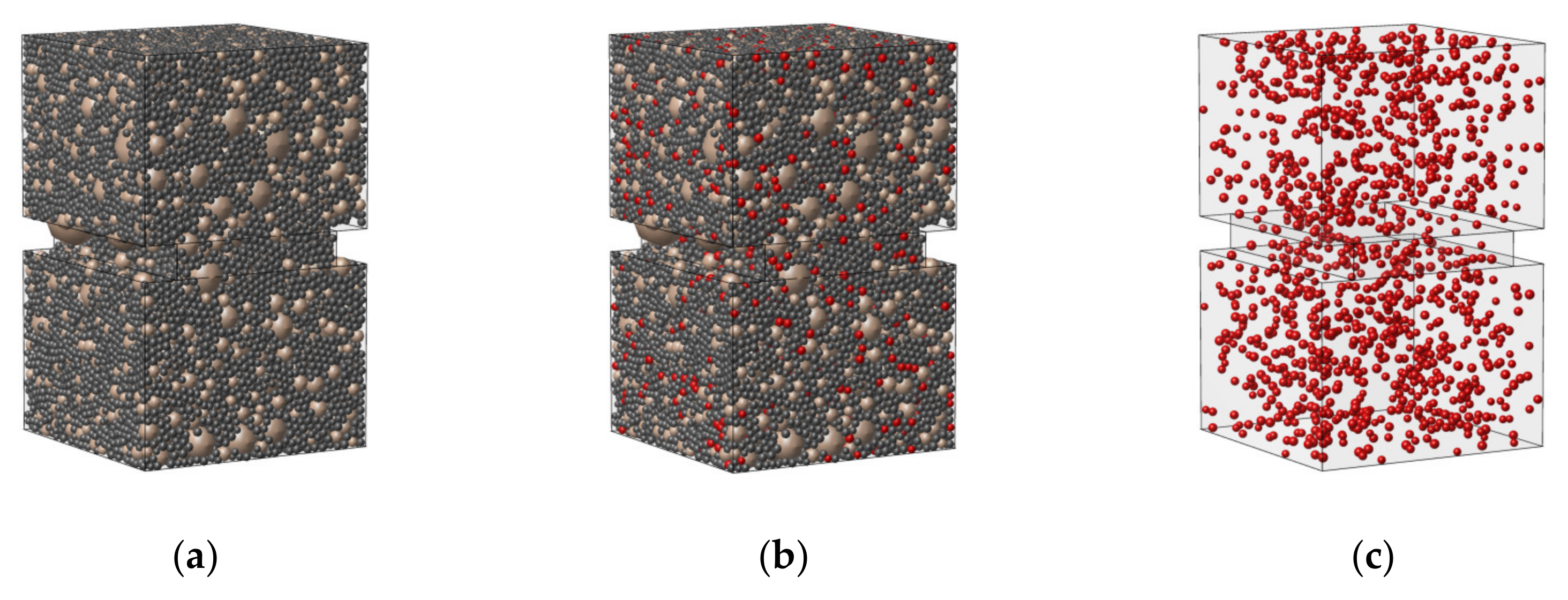
The AM–0 model is a prismatic specimen (8.0 × 5.0 × 5.0 cm3) that follows the specified dimensions, aggregate gradation, and mastic characteristics detailed in Table 1. In the assembly, particles larger than 2.0 mm represent the aggregates, while those between 1.5 and 2.0 mm represent the mastic. The AM–0 model comprises 25,374 particles, 138,573 particle–particle contacts, and 1537 particle–wall contacts. The AM–t–0 model follows the same dimensions as the AM–0 model and adopts a similar particle size distribution for both aggregates and mastic. However, the specimen includes a notch measuring 0.80 cm in length and height on both sides at mid-height to facilitate fracture initiation and localisation. The relationship between the minimum specimen width (between notches) and the maximum aggregate size is approximately 2.5, which is considered an acceptable ratio (see Figure 1 and Figure 2).
The AM–t–0 model comprises 24,606 particles, 133,620 particle–particle contacts, and 1537 particle–wall contacts. The air void content in both specimens is 3.8%. Table 1 also presents the number of aggregate particles retained on each sieve size, along with the mastic elements and their equivalent volume. Figure 1 and Figure 2 illustrate the schematic representations of the AM–0 and AM–t–0 models.
To assess the effect of capsules on the modulus and tensile strength of asphalt mixtures, an in-depth analysis is conducted by adopting three capsule contents, expressed as mass proportions of the total asphalt mixture—0.30, 0.75, and 1.25 wt.%—respectively referred to as AM–30, AM–75, and AM–125 (dynamic loading), and AM–t–30, AM–t–75, and AM–t–125 (tensile loading). These values are generally regarded as lower and upper limits for self-healing applications in experimental investigations, with pavement researchers typically selecting values within this range [14,16,44]. Figure 1 and Figure 2 show schematic representations of the asphalt mixture models containing capsules.
The number of capsules inserted into the AM–30, AM–75, and AM–125 assemblies is 519, 1251, and 2128, respectively, while for the AM–t–30, AM–t–75, and AM–t–125 specimens, the corresponding numbers are 503, 1210, and 2061. In both cases, the air void content ranges between 3.8% and 4.1%. These capsules have diameters ranging from 1.5 to 2.0 mm, with an average of 1.75 mm. The selected capsule size aligns with the range commonly used in experimental tests [10,45,46]. Capsules that are too small carry only a limited amount of rejuvenator, whereas larger capsules are more prone to breakage during manufacture, potentially releasing the rejuvenator prematurely and negatively affecting the performance of asphalt pavements in the early stages of service [7,18].

3.2. Contact Modelling Approach

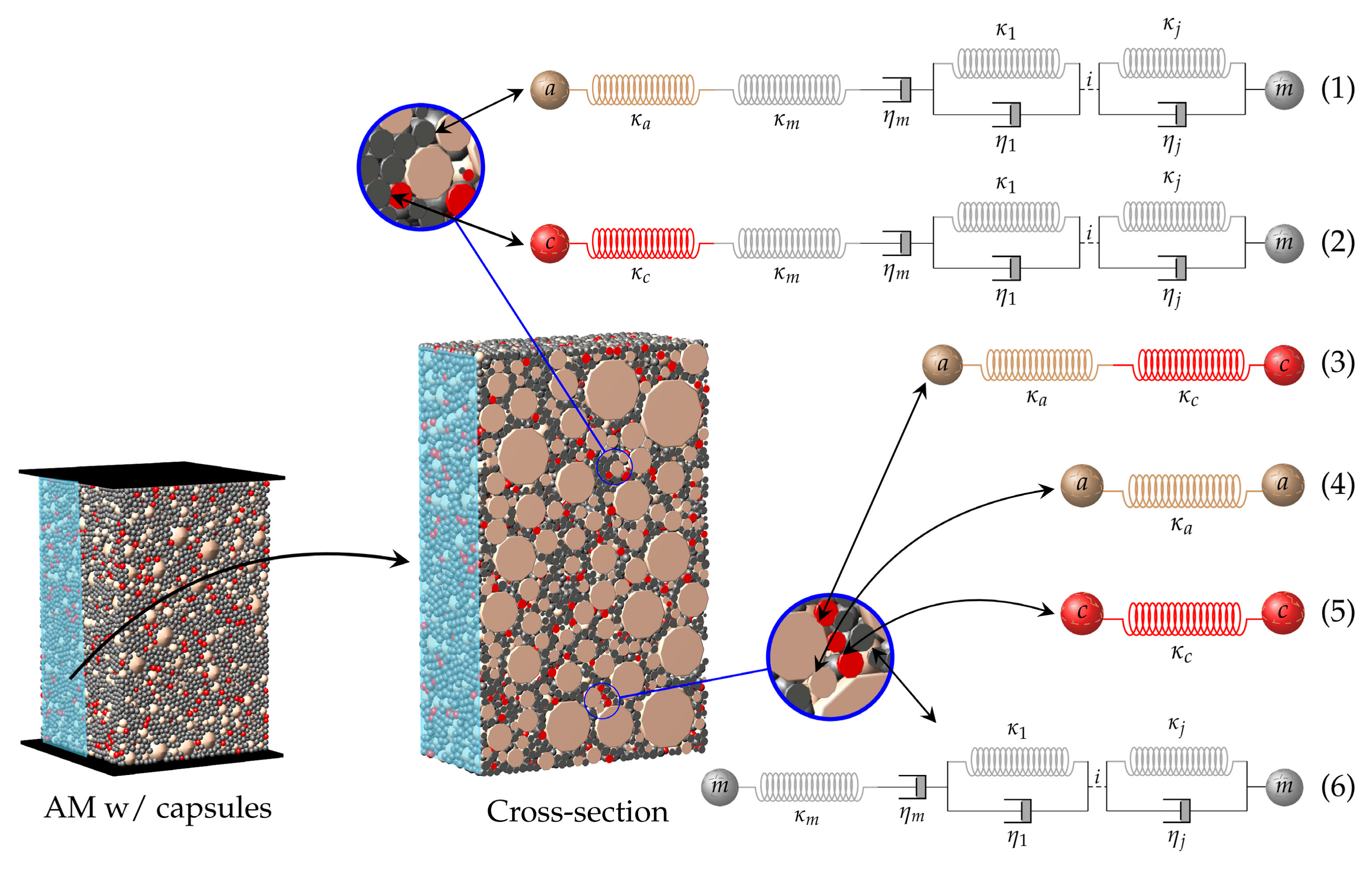
From Figure 1 and Figure 2, the AM–0 and AM–t–0 specimens comprise two material phases: aggregate and mastic, positioned between two structure walls where the loading conditions are applied. In both models, six types of interaction exist, including contacts between adjacent aggregates, within the mastic phase, aggregate–mastic, and between any particle and the loading walls (aggregate–wall and mastic–wall). When capsules are incorporated (AM–30, AM–75, AM–125, AM–t–30, AM–t–75, and AM–t–125), these previous interactions remain, with the addition of aggregate–capsule, mastic–capsule, and capsule–wall contacts. This study treats capsules as an elastic material, consistent with other DEM simulations [28]. In addition, capsule–capsule contacts are also considered.
Under dynamic loading, two contact models represent all interactions in the AM assemblies (Figure 3). A linear elastic contact model describes interactions between adjacent aggregates (4), aggregate–capsule (3), and capsule–capsule (5) contacts (when capsules are present). Previous studies indicated that interactions involving mastic particles (aggregate–mastic (1) and mastic–mastic (6)) should follow a viscoelastic approach, particularly when represented by a generalised Kelvin (GK) contact model [26,35,47]. For AM–30, AM–75, and AM–125, the mastic–capsule (2) interaction also follows this viscoelastic representation.
In the adopted approach, the capsule content is directly represented, and its influence is governed by the number of contacts within the volume. For this reason, the same contact models are applied to all interactions involving capsules. As an approximation, the aggregate–capsule and mastic–capsule follow the aggregate–mastic and mastic–mastic contact model with the stiffness associated with the capsule. The capsule–capsule contact model follows an elastic behaviour, as calibrated in Section 3.3.1.
For both dynamic and tensile loading cases, however, the relationship between any particle and the loading walls is treated with an elastic approach. Table 2 presents the number of interactions for each type of contact in the particle models.

3.2.1. Elastic Contact Model

In the linear elastic contact model, the relationship between the Young’s modulus of the equivalent continuum material ( E ξ ) and the contact stiffness in the normal direction ( k ξ n ) is given by [42]
k ξ n = E ξ A ξ L ξ
where L ξ is the length associated with the contact interaction, A ξ is the effective contact area between the interacting particles, and ξ may refer to either a or c to represent the aggregate or capsule, respectively. The contact stiffness for the shear direction ( k ξ s ) is determined as the product between k ξ n and the contact stiffness ratio α, which follows the calibrated value for each specific contact interaction. For these interactions, the contact stiffness ratio α is set to 0.10 for a macroscopic Poisson coefficient of 0.40 [35].
The relationship between the contact force increments ( F i n and F i s ) and relative displacement increments ( x n and x i s ), associated with a linear elastic contact model in a DEM cycle, are given by
F i n = k ξ n x n = k ξ n x ˙ i n t n i F i s = k ξ s x i s = k ξ s x ˙ i s t x n n i
where i is the contact direction.

3.2.2. Generalised Kelvin Contact Model

The GK contact model combines, in series, a Maxwell model—a combination of an elastic and a viscoplastic unit placed in series, describing the instantaneous response and permanent deformation—and j-chains of the Kelvin model—a combination of springs and dashpots arranged in parallel that describes the delayed elastic response [35]. The number of Kelvin chains is determined during the calibration process, based on the material’s composition and behavioural complexity. Experimental results can be used to facilitate the calibration process. Compared to the commonly used Burgers contact model [1,22,48,49,50], the proposed GK contact model provides a more accurate rheological representation over a wider range of frequencies and temperatures. In 2D, a generalised Maxwell model [51,52] and a generalised Kelvin model [53], similar to the adopted 3D GK contact model, have also been proposed to improve the numerical predictions.
The total contact force ( f ) is assumed to be the same for each of these elements. The total displacement of the GK model ( u t ), on the other hand, results from the sum of the displacement corresponding to the Maxwell unit ( u m )—comprising the elastic ( u e l ) and viscoplastic ( u v p ) displacements—and the cumulative displacement arising from the Kelvin chains ( i = 1 j u v e i ). The total displacement increment ( Δ u t ) is
Δ u t = u e l t + Δ t u e l t + u v p t + Δ t u v p t + u v e i t + Δ t u v e i t
The time-dependent displacement in the GK contact model follows an incremental formulation, based on the hereditary integral formulation of the relationship between force and the rate of creep compliance ( J ), and is expressed as
u ξ t = J ξ 0 f t + 0 t d J ξ t t d t t f t d t
where ξ may refer to either ve or vp, representing the viscoelastic and viscoplastic elements of the generalised model, and t′ is an integration variable. The initial creep compliances for both displacement components are assumed to be zero.
The displacement increment ( Δ u ξ ) for the viscoelastic and viscoplastic elements is determined by deriving Equation (4). The elastic displacement increment ( Δ u e l ) and corresponding displacement at time t + Δ t , on the other hand, reflect the direct relationship between the contact force and the stiffness in the Maxwell element ( κ m ). The displacement increment of these components is given by
u e l t + Δ t u e l t = + c e l f t
u v e t + Δ t i u v e t i = + u v e t i e Δ t τ i 1 + Δ t e Δ t 2 τ i c v e i f t + Δ f 2
u v p t + Δ t u v p t = + Δ t c v p f t + Δ f 2
where c e l , c v e i , and c v p are the inverses of contact parameters κ m , η i , and η m , respectively, and τ i corresponds to the retardation times defining the relationship between the viscosity and stiffness of the ith-element of the delayed elastic chain.
The total displacement increment ( Δ u t ) of the model is calculated by substituting the displacements from Equations (5)–(7) into Equation (3), and can be simplified into a pseudo-elastic formulation, given by
Δ f = u ¯ c t
where c t is the total flexibility matrix of the GK contact model—the sum of the elastic and time-dependent components, and u ¯ is the pseudo-elastic displacement. The pseudo-elastic displacement increment Δ u ¯ is defined as
Δ u ¯ = Δ u 1 Δ t c 1 f t
where c 1 and Δ u 1 are the flexibility matrix and displacement increment of the time-dependent portion of the contact model, respectively. The displacement increment Δ u 1 is then given by
Δ u 1 = Δ u i = 1 j u v e t i e Δ t τ i 1
The total contact force at time t + Δ t results from the sum of the contact force at the previous time t and the increment defined in Equation (8).

3.2.3. Bilinear Softening Damage Model

Asphalt pavements are susceptible to damage, with cracking being the most common form of distress in these infrastructures. Cracks typically initiate due to traffic loading and climatic conditions at intermediate temperatures. Within this temperature range, damage in asphalt mixtures tends to propagate through softer forms of degradation. Previous DEM studies have shown that softening-based models improve the representation of damage propagation phenomena in asphalt mixtures [54,55,56]. By adopting a linear model, Peng and Gao [25] assessed the impact of air void size and distribution on the indirect tensile strength of mixtures at different temperatures and loading directions. Dan et al. [57] investigated the effect of notch eccentricity on low-temperature crack propagation in asphalt mixtures under single-edge notched bend test simulations.
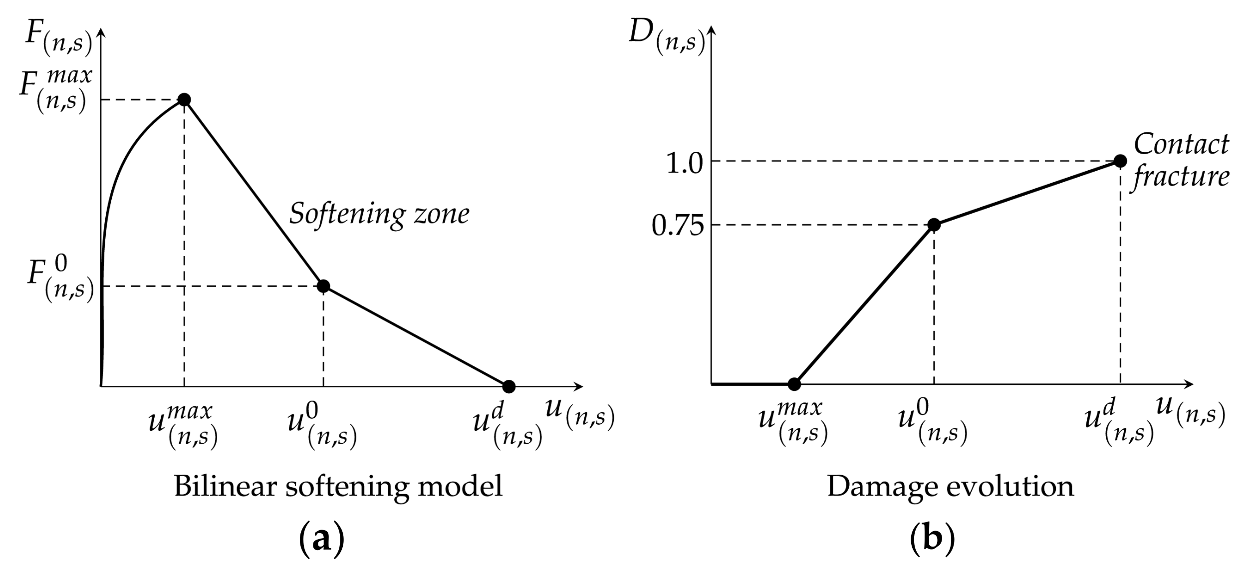
Most studies, however, have adopted linear softening models in DEM numerical simulations. In order to enhance the potential to represent the overall time-dependent damage behaviour of asphalt materials, this study adopts a bilinear softening model (see Figure 4), previously proposed in [36], to account for post-peak behaviour in numerical tests considering a softening damage evolution response. Under tensile loading, a bilinear softening damage model—associated with either the elastic or GK contact model (Figure 4), depending on the nature of the contact—is adopted to assess damage evolution [36]. The Elastic–Bilinear model is used for aggregate–aggregate, aggregate–capsule, and capsule–capsule contacts, while the GK–Bilinear model is applied for interactions involving mastic particles (aggregate–mastic, mastic–capsule, and mastic–mastic). This damage model has been shown to significantly improve material representation compared to brittle and linear damage models.
The bilinear damage model requires the following input parameters: the maximum tensile strength ( σ t ), the contact fracture energy in mode I ( G I ), the maximum contact cohesion stress (τ), the contact friction term (μ), and the contact fracture energy in mode II ( G I I ). The force–displacement relationship presented in Figure 4 is defined as follows:
F ( n , s ) m a x = σ ( n , s ) m a x A c
where σ ( n , s ) m a x refers to σ t (normal direction) or τ (shear direction).
The GK–Bilinear model adopts a total contact displacement-controlled criterion. Once the maximum displacement allowed before damage ( u n , s m a x ) is reached, either in the normal or shear direction, the maximum contact strength gradually decreases based on the accumulated damage factor D n , s . In the elastic approach, the total contact displacement includes both an elastic and a damage term, whereas in scenarios adopting the GK–Bilinear contact model, the total contact displacement includes both a viscoelastic and a damage component. From Figure 4, when the elastic behaviour is adopted, u n , s m a x corresponds to the peak strength. However, under a viscoelastic approach, u n , s m a x does not necessarily correspond the to the peak load due to the time-dependent behaviour of the interaction.
The post-peak load zone is characterised by three distinct regions, defined by the displacements u ( n , s ) m a x and u ( n , s ) 0 ; the second by u ( n , s ) 0 and u n , s d ; and the final region, where the maximum contact displacement u n , s exceeds u ( n , s ) d . These parameters, which govern the force-displacement relationships shown in Figure 4, are given by
u n , s m a x = F n , s m a x k n , s
u n , s 0 = 0.75 G θ A c F n , s m a x + u n , s m a x
u n , s d = 5.0 G θ A c F n , s m a x + u n , s m a x
F n , s 0 = 0.25 F n , s m a x
where G θ refers to G I (contact fracture energy in mode I) and G I I (contact fracture energy in mode II)—both terms corresponding to the area of the softening region—and k n , s may refer to either the contact stiffness from the elastic interaction types or the associated Kelvin model from time-dependent interaction types. In either case, this relationship is defined by Equation (1). For time-dependent interactions, however, the spring stiffness of the Maxwell unit ( k m ) is adopted as the modulus of the material from Equation (1).
In the bilinear softening model, damage is defined as a function of the maximum displacement u n , s in the normal and shear directions. Note that the accumulated damage factor D n , s varies between zero (intact contact) and 1.0 (fully cracked contact), as illustrated in Figure 4. The total damage factor is assumed to be the sum of the contact damage in the normal D n and shear D s directions.
Once within the softening region, the contact tensile and cohesive strengths are adjusted accordingly based on the updated value for the damage factor D , as described by the following:
F n m a x , u p d a t e d = 1 D × F n m a x
C m a x , u p d a t e d = 1 D × C m a x
F s m a x = C m a x , u p d a t e d + F n
The contact forces (in both the normal and shear directions), adjusted according to the updated strength values at each step following the attainment of their peak values, are given by
F n = F n m a x , u p d a t e d
F s = F s m a x , u p d a t e d F s F s
Finally, once the accumulated damage factor D reaches its maximum value, the contact is fully fractured. In this scenario, the contact forces are set to zero in tensile loading simulations. However, the contact may still function under pure frictional conditions, following a viscoelastic model under compression/shear.

3.3. Contact Model Parameter Calibration

3.3.1. Elastic Model

The aggregate Young’s modulus ( E a ) is taken as 61 GPa, derived from the previous calibration presented by Câmara et al. [35]. The relationship between E a and the contact stiffness in the normal and shear directions ( k a n and k a s ) is defined in Equation (1).
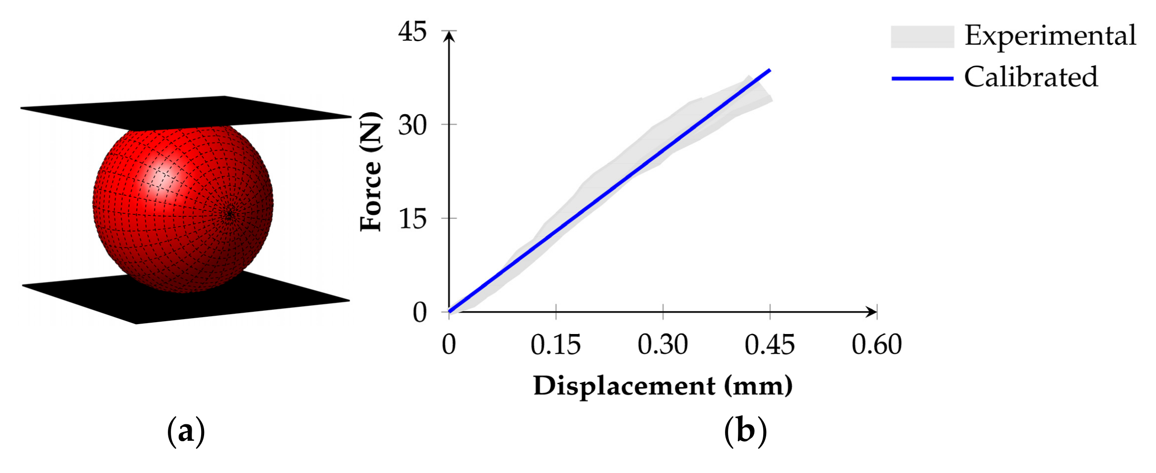
The contact stiffness calibration process for the capsules follows a similar procedure. The capsule continuum equivalent Young’s modulus ( E c ) is calibrated following the force-displacement experimental results from a uniaxial compression test on a single capsule [58]. In [58], the authors tested several capsules, which exhibited initial rupture at 33.0 ± 2.2 N for an average deformation of 0.50 mm. At this point, however, the amount of rejuvenator released was minimal due to the encapsulation method. This represents an advantage for the present calibration, as the aim of this study is to assess the effect of the capsules solely on the mechanical properties of asphalt mixtures, thus avoiding the influence of the rejuvenator itself.
To determine the capsule continuum equivalent Young’s modulus, a virtual monotonic compression test is performed on a single capsule (1.50 mm in size) positioned between two parallel walls (Figure 5a), similar to the procedure used by Zhang et al. [29], who defined the mechanical properties of capsules using FEM and DEM simulations to investigate their effects on asphalt mixture performance. A vertical velocity of 1.0 × 10 5 m/s is applied to the upper wall in the downward Z-direction, while the bottom wall remains fixed in all directions. The results shown in Figure 5b demonstrate a close agreement with the experimental response [58] for a capsule stiffness modulus of 3.35 × 10 4 kPa. The resulting capsule contact stiffness in the normal and shear directions ( k c n and k c s ) is derived using the relationship from Equation (1).
In the asphalt mixture model, for interactions between two different material types, such as aggregate–capsule contacts, an equivalent contact stiffness ( κ e q n ) is estimated by following two elements in series to represent the effective contact stiffness of the interaction. The equivalent elastic relationship for the normal direction is given by
κ e q n = κ m a t 1 κ m a t 2 κ m a t 1 + κ m a t 2
where κ m a t 1 and κ m a t 2 , calculated in accordance with Equation (1), represent the elastic units of particles 1 and 2, respectively, in a particle–particle system. The contact stiffness for the shear direction follows the same relationship described in Section 3.2.1.

3.3.2. Generalised Kelvin Contact Model

The calibrated macroscopic parameters from [35] are adopted in the DEM simulations to characterise the viscoelastic interactions, which are modelled using the GK contact model in the AM models (see Figure 3). These macroscopic properties are derived through a fitting procedure that minimises the error of a function accounting for experimental data. During this process, the number of Kelvin chains in the model is determined via an iterative procedure that also reduces the predicted error, ensuring the best agreement with the reference experimental results. As shown in Table 3, three Kelvin chains were required to accurately represent the time-dependent interactions within the asphalt mixture models at 20 °C [35].
The macroscopic properties from Table 3 are then converted into contact parameters—stiffnesses ( k ξ n ) and viscosities ( η ξ n ), where ξ takes the value of i for the ith-viscoelastic element in the Kelvin chain, and m for the elastic and viscoplastic elements of the Maxwell component—based on Equation (1) for the normal direction. The shear contact stiffness is calculated using the relationship previously described in Section 3.2.1 (α = 0.10 [35]).
The same methodology applied for interactions represented by an elastic contact model—where different types of particles are in contact—to calculate an equivalent contact stiffness relationship (see Equation (20)) is adopted for viscoelastic interactions involving different material types, such as aggregate–mastic and mastic–capsule contacts. In this case, however, the equivalent normal contact stiffness ( κ e q n ), estimated from two springs in series (Figure 3), replaces the elastic spring in the Maxwell unit ( κ m ).

3.3.3. Bilinear Softening Model

The bilinear softening damage model employs the calibrated parameters from [36] to represent damage initiation and propagation when asphalt mixtures are subjected to tensile loading. Table 4 presents the contact parameters for the GK–Bilinear contact model in both the normal and shear directions. Note that although the maximum contact cohesion stress and the contact fracture energy in mode II—associated with the shear direction—are computed, these parameters, within the selected range of values, do not significantly influence the predicted macroscopic response under tensile loading. The damage properties of capsule–mastic interactions follow those defined for aggregate–mastic interactions. The same applies to aggregate–capsule and capsule–capsule contacts. In tensile tests, it is assumed that the mastic surrounding the capsules provides their contact tensile strength.

4. Numerical Tests

This study evaluates the effect of capsule incorporation on the mechanical properties of asphalt mixtures using the VirtualPM3DLab DEM software. The validation of the adopted numerical implementation and the calibration of the contact models presented in Section 3 was carried out in [35,36].
Uniaxial tension–compression sinusoidal tests are simulated with an imposed strain amplitude of 1.0 × 10 4 m/m, measuring the stiffness and phase angle across loading frequencies of 2, 5, 10, and 20 Hz. A parametric study is also conducted to assess the influence of capsule continuum equivalent Young’s modulus on the stiffness behaviour of mixtures. In this analysis, the impact of capsule content on the rheological response of asphalt mixtures is evaluated. Following, the impact of capsule content on the tensile strength of asphalt mixtures with an imposed constant velocity of 8.0 × 10 4 m/s is assessed.
In both numerical tests, simulations are carried out for a group of asphalt mixtures, including control specimens (AM–0 and AM–t–0) and specimens containing capsules (AM–30, AM–75, AM–125, AM–t–30, AM–t–75, AM–t–125). Simulations assume that the load is applied to the upper wall in the vertical direction, while the bottom wall is constrained in all degrees of freedom. A timestep of approximately 2.0 × 10 7 s/step is adopted in the numerical analyses. The same boundary and loading conditions are applied to all specimens (with or without capsules) under their respective loading scenarios.

5. Results and Discussion

5.1. Tension–Compression Sinusoidal Test

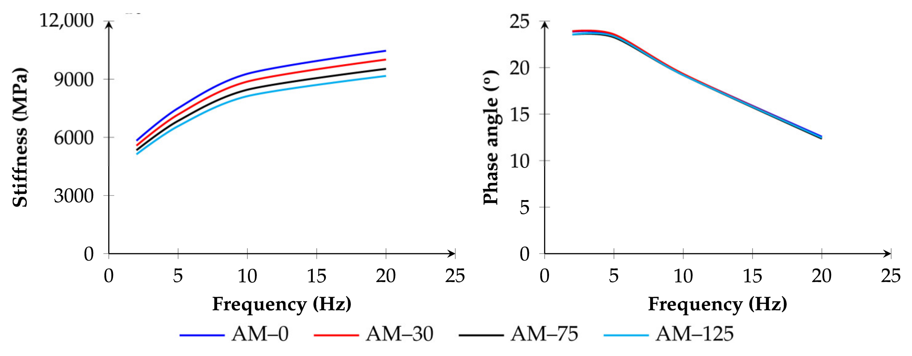
Figure 6 illustrates the effect of incorporating capsules on the stiffness behaviour of asphalt mixtures under dynamic loading. The stiffness modulus progressively decreases as the capsule content increases. As shown in Table 5, a higher capsule content results in a more pronounced reduction in stiffness. On average, the reductions observed for specimens AM–30, AM–75, and AM–125 are 4.3%, 8.7%, and 12.3%, respectively.
Across all loading frequencies, the stiffness results show no substantial variation. The reduction in stiffness modulus at frequencies of 2, 5, 10, and 20 Hz remains similar for each capsule content case, with a maximum variation of only 0.3% for the highest capsule content. The impact on the phase angle is also minimal across all capsule ratios. The deviation in phase angle relative to the reference specimen (AM–0) remains below 0.8% across all frequencies, with differences ranging between −0.31° and 0.07° (see Table 5).
The DEM results indicate that higher capsule ratios influence the stiffness modulus of asphalt mixtures more significantly than the phase angle, which remains nearly constant regardless of the capsule content. These findings are expected, as the capsules act similarly to aggregates with a low modulus, thus reducing the overall stiffness of the mixture in proportion to their concentration.
These results are consistent with previous DEM-based analysis [47], where the authors investigated the effect of activated capsules (particles representing the blend of rejuvenator and asphalt mastic) on the post-healed rheological behaviour of asphalt mixtures, using similar capsule contents and loading conditions. For capsule concentrations of 0.30, 0.75, and 1.20 wt.%, the reported reduction in stiffness modulus ranged from 4.9% to nearly 30%, while the phase angle remained largely unaffected.
Several factors may account for the smaller effect of capsules observed in the present modelling results compared to those reported in [47]. The more pronounced reduction in stiffness modulus found in [47] can be primarily attributed to the additional effect of rejuvenator release within the asphalt mixtures. Interestingly, in both numerical analyses, the phase angle remained nearly constant, indicating that the rheological behaviour of asphalt mixtures with these capsule ratios is not significantly altered in terms of their elastic–viscous components, even at a high capsule content of 1.25 wt.%.
Nevertheless, the incorporation of capsules into asphalt mixtures should be undertaken cautiously to avoid an excessive reduction in stiffness modulus of asphalt pavements. Following the same reasoning adopted in [47], a capsule content of 1.25 wt.% may be considered excessive; accordingly, adopting a lower content, such as 0.75 wt.%, would be more appropriate for self-healing purposes. Based on this hypothesis, a capsule dosage of 0.75 wt.% alone would lead to a stiffness reduction on average of approximately 8.7% in the asphalt mixture. According to the findings in [47], this effect on stiffness could reach a maximum level between 13.5% and 18.4% considering the rejuvenator effect, depending on the rejuvenator release rate considered.
Most experimental studies have reported a reduction in the stiffness modulus ranging from 10% to 30%, depending on the test type, capsule content, capsule size, rejuvenator release rate, and other influencing factors [18,19,59]. Li et al. [7] demonstrated that both capsule type and content influence the performance of asphalt mixtures after investigating three different types of capsules. Kargari et al. [16] observed a reduction in stiffness of approximately 11% and 15% for capsule contents of 0.35 wt.% and 0.70 wt.%, respectively, in laboratory tests. Similarly, experimental tests conducted by Micaelo et al. [58] reported a 14% reduction in the stiffness for mixtures containing 1.00 wt.% capsule content.
The reduction in stiffness modulus observed in the present study is considerably less pronounced than that reported in most experimental investigations for similar capsule contents and capsule types. This may be primarily because the present numerical study considers only the physical presence of the capsules, excluding the effect of rejuvenator release that is typically included in experimental work. Most experimental studies assess the combined effect of capsules and rejuvenators on the modulus of asphalt mixtures, often overlooking the isolated influence of the capsules themselves. Few studies have assessed the impact of the capsule alone, without rejuvenator. One such example is the study by García et al. [34], who demonstrated, in a laboratory, that even capsules without rejuvenator incorporation can affect the stiffness of mixtures. This underscores the importance of investigating the standalone effect of capsules as a critical step in improving the design of self-healing asphalt technologies.
In recent years, several studies have investigated the incorporation of calcium–alginate capsules into the mechanical behaviour and self-healing capacity of asphalt mixtures [45,46]. These capsules offer advantages over alternative types, such as the ease of production, lower costs, and the ability to encapsulate larger amounts of rejuvenator [10]. Although experimental studies have examined the influence of capsules with various materials and activation mechanisms, such approaches do not allow for an isolated assessment of the mechanical effect of the capsules themselves [60,61]. Numerous capsule-related parameters can influence the stiffness of asphalt materials under dynamic loading. Different characteristics may define the calibration parameters of capsules used in asphalt mixtures, such as the constitutive material and the elastic properties that govern their interactions with other constituents of the mixture.
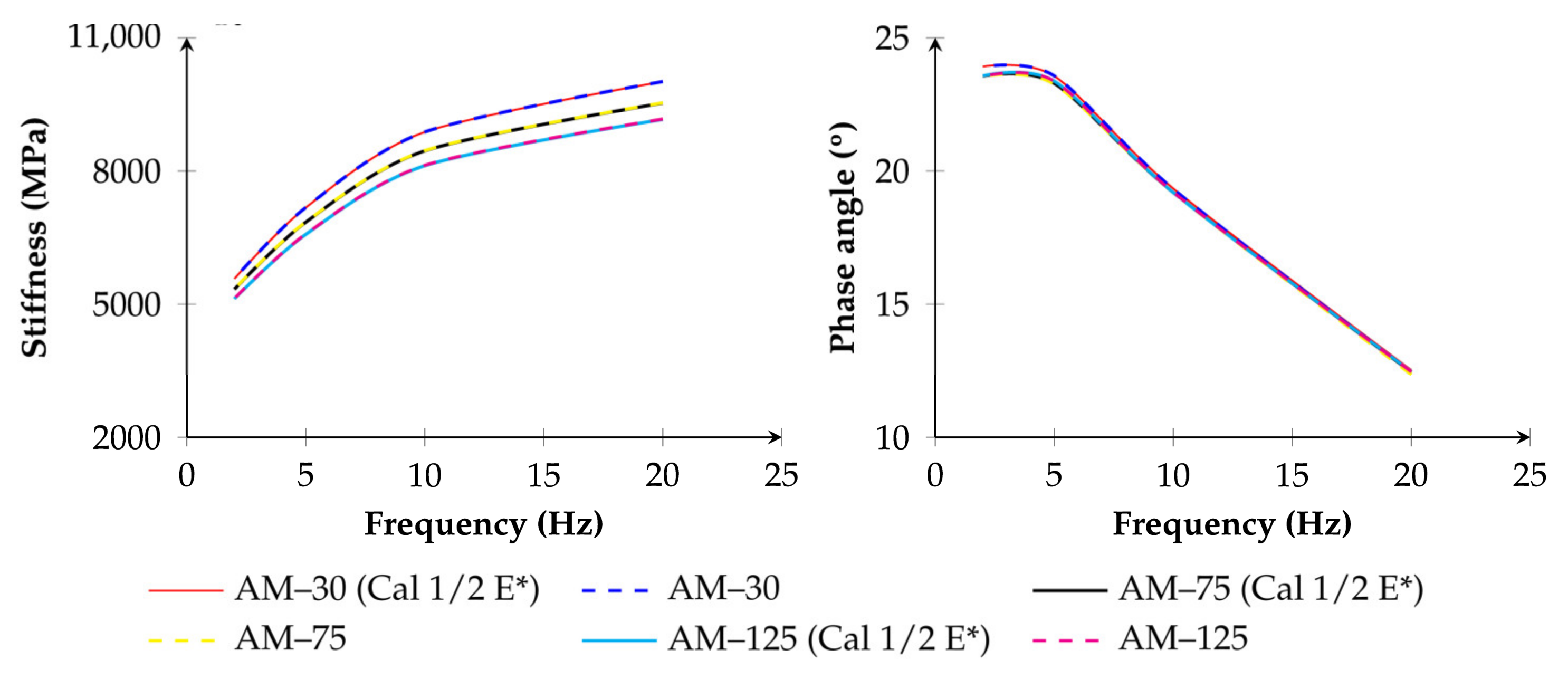
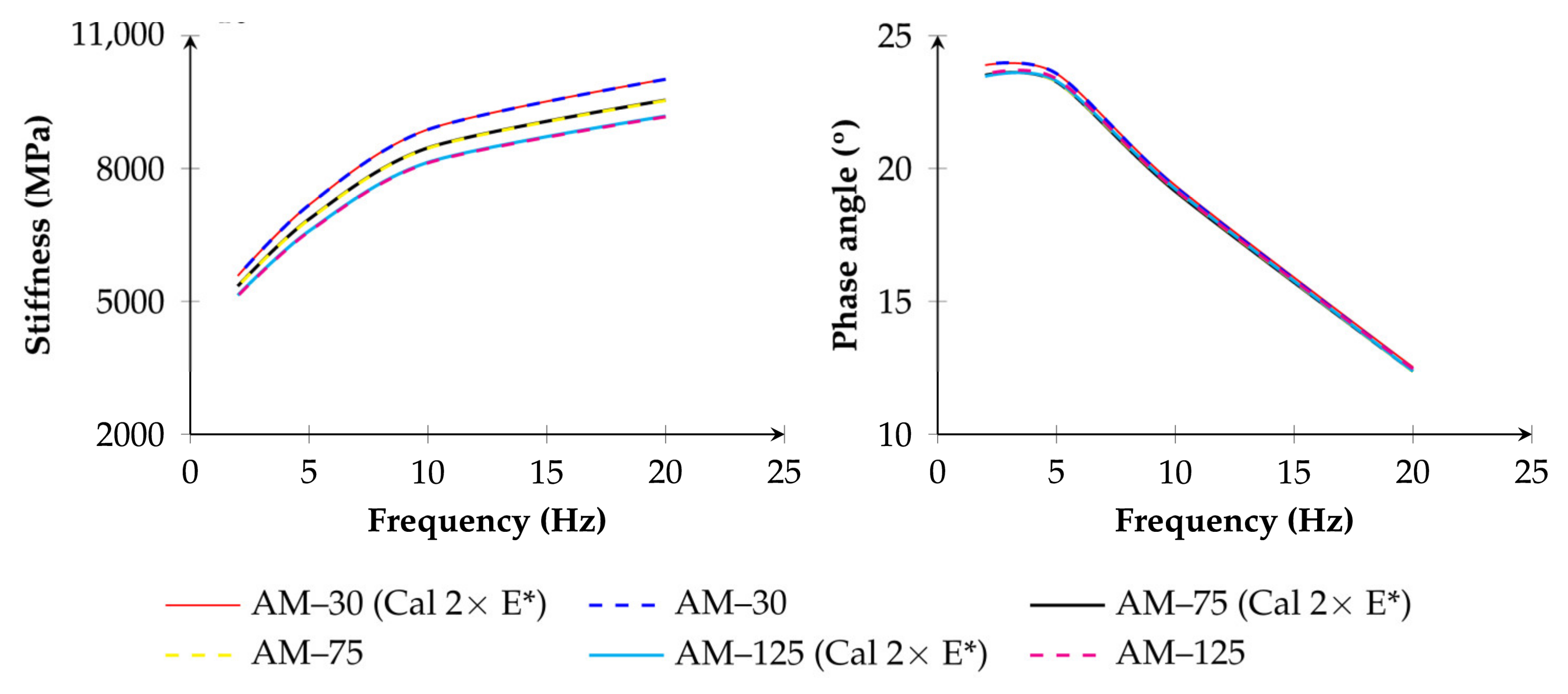
To analyse the material properties of the capsules, this next analysis investigates the effect of the capsule continuum equivalent Young’s modulus on the stiffness properties of asphalt mixtures. The modulus used for capsules in the AM assemblies was calibrated based on the calcium–alginate capsules used in previous experimental tests [58]. To assess this influence on asphalt mixtures subjected to tension–compression loading, the study considers two hypotheses for the capsule continuum equivalent Young’s modulus: (a) half of the calibrated value and (b) twice the calibrated value.
Figure 7 and Figure 8 show the influence of this parameter on the stiffness and phase angle of the specimens (AM–30, AM–75, AM–125), compared to those obtained using the calibrated capsule continuum equivalent Young’s modulus. Within the range of values considered, the influence of this parameter on the AM specimens does not significantly affect their stiffness behaviour, regardless of the capsule content in the numerical models. The variation in the rheological properties is minimal and primarily dependent on the capsule content incorporated into the assemblies. When adopting half of the calibrated value, the stiffness of asphalt mixtures reduces by less than 0.10% on average, while a slight increase in the phase angle—nearly 0.14% on average—is observed. Conversely, a higher capsule continuum equivalent Young’s modulus results in a marginal increase in stiffness and a slight reduction in the phase angle.
This parametric analysis suggests that the capsule ratio is the primary factor influencing the stiffness of asphalt mixtures when using this specific capsule type. To generate a more significant impact, the capsule continuum equivalent Young’s modulus would need to be either considerably lower or higher than the value derived from the experimental study [58]. This would likely require the use of capsules composed of alternative materials with different mechanical properties. Additional significant effects may arise from the action of the rejuvenator and breakage of capsules in simulations that include fracture–healing processes.

5.2. Tensile Strength Monotonic Test

The isolated effect of capsules—excluding the additional influence of rejuvenator release—is also evaluated in terms of tensile strength of notched asphalt mixtures under monotonic tensile loading. Figure 9 presents the stress–strain response of mixtures for three capsule contents. The initial elastic behaviour of the specimens is not affected by the presence of capsules, with a similar trend observed across all assemblies up to the peak tensile stress. The incorporation of capsules leads to a reduction in tensile strength, with decreases ranging from 4.3% to 12.4%, depending on the capsule content. The highest reduction is observed for the AM–t–125 specimen. The post-peak region of the stress–strain curve follows a similar trend for all analysed assemblies, suggesting that the capsule content mainly affects the tensile strength value. Consequently, the overall fracture resistance of the specimens appears to be only marginally influenced.
The influence of capsules is also reflected in the damage evolution observed during tensile simulations. As shown in Figure 9, the evolution of cumulative damage follows a similar pattern across all specimens. When considering the overall damage—taking into account the entire volume of each AM–t specimen—the damage levels reach approximately 6.2% at a strain level of around 1.75%, regardless of the capsule content.
In general, notched asphalt mixtures are expected to exhibit a concentration of damage in the vicinity of the notch region. Figure 9 also shows the local damage evolution within the notch region. By the end of simulations, damage levels in this area range between 31% and 34.5%, depending on the specific assembly. These values are indicative of significant localised damage, typically associated with well-defined fracture planes initiating from the notch tips.
Despite the uniform distribution of capsules in the numerical specimens—replicating the typical configuration used in experimental tests—the influence of existing capsules on the damage magnitude in the notch-tip zone is minimal. A slight reduction in localised damage is observed in the capsule-containing specimens compared to the control specimen (AM–t–0), as can be seen in Figure 9. However, the overall impact remains limited.

5.2.1. Contact Damage Evolution

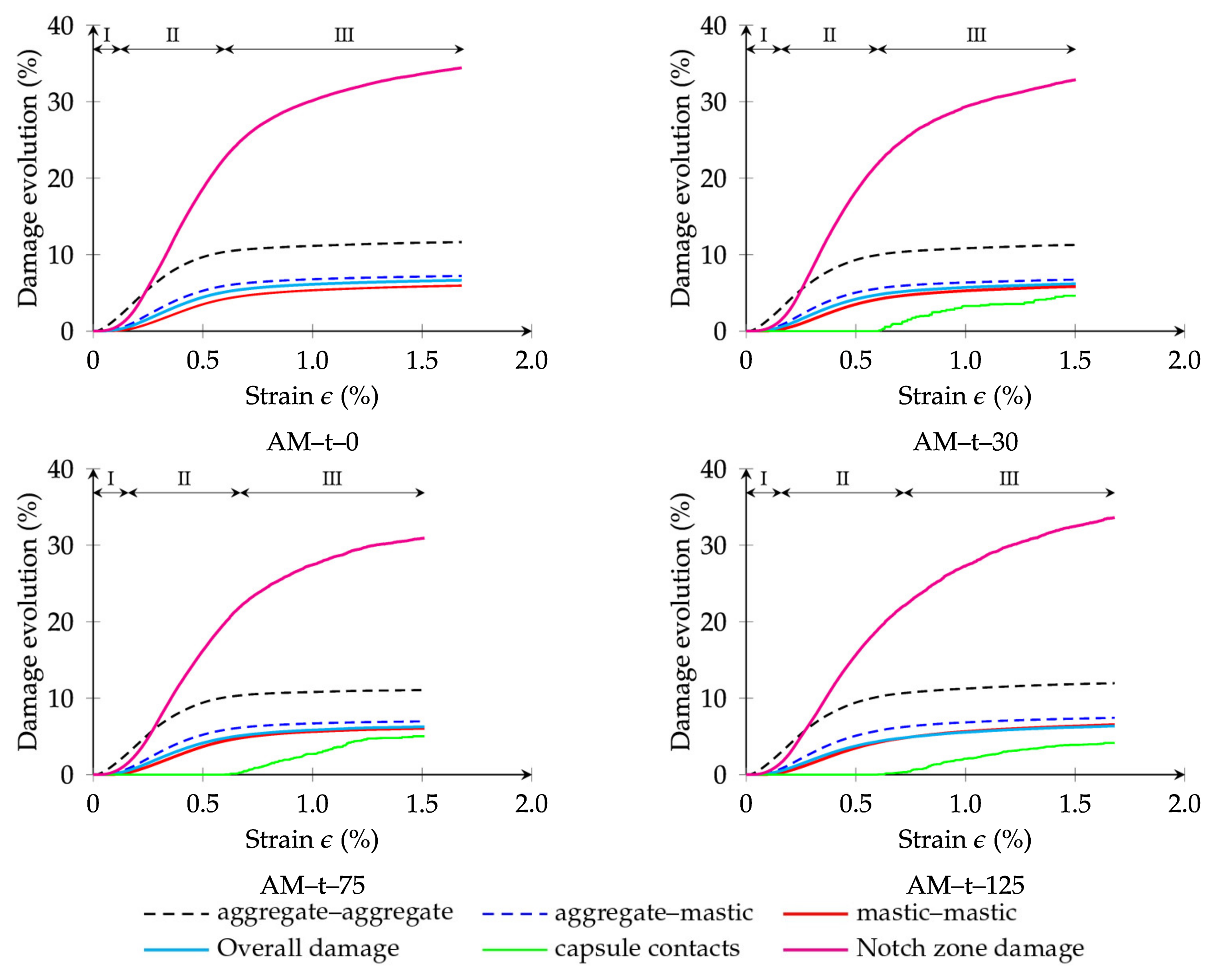
The evolution of contact damage (overall and notch region) is the cumulative result of the damage from the different types of particle interactions. These include aggregate–aggregate, aggregate–mastic, mastic–mastic, and, when applicable, interactions involving capsules—namely aggregate–capsule, mastic–capsule, and capsule–capsule contacts. Figure 10 presents the damage evolution for each contact type, providing further insight into the progression of damage throughout the simulations. It also illustrates the damage evolution within the region between the notch tips, where failure is most likely to occur.
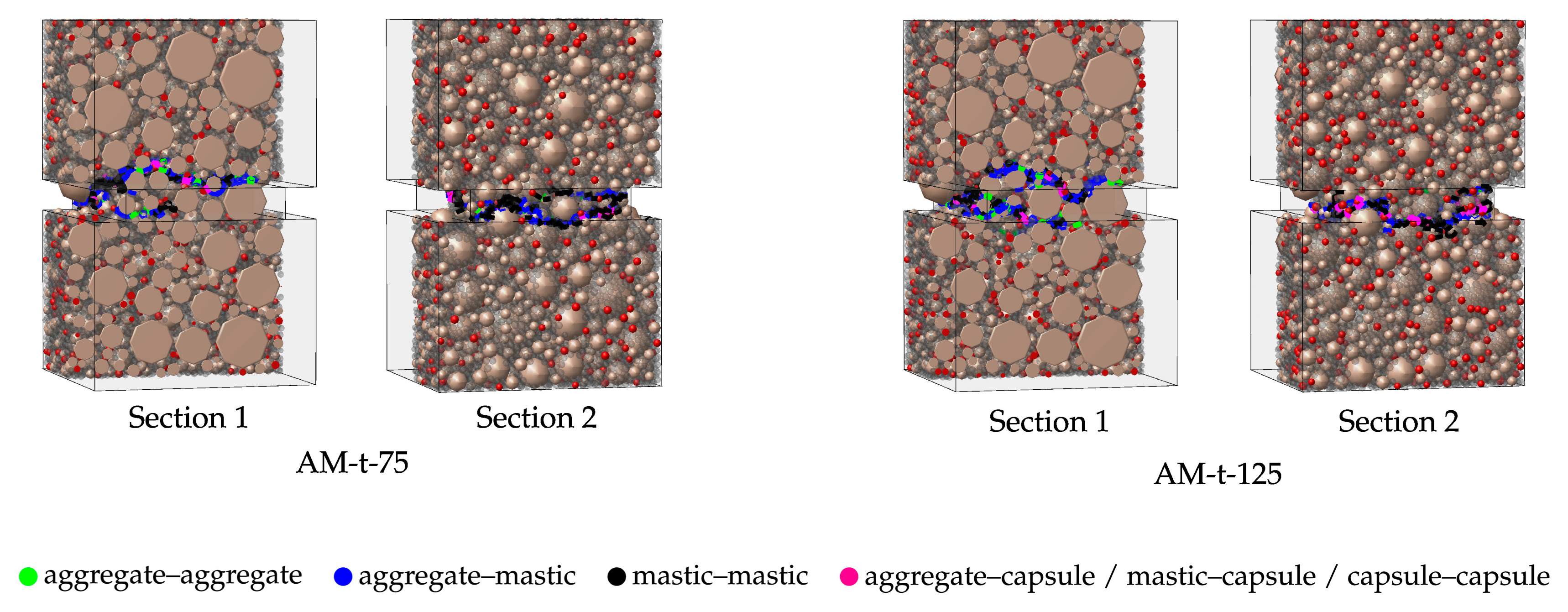
In both specimen scenarios (with and without capsules), and regardless of the capsule content, the evolution of contact damage during numerical tensile simulations can be divided into three distinct stages:
  • Stage 1: This stage (strain ε ≤ 0.12%) is characterised by the absence of contact damage in interactions involving mastic and capsules. The observed response primarily results from the initial rearrangement of the constituent materials in the asphalt mixtures in response to internal air voids and the deformability of the material phases. The elastic response from the contact models—either linear elastic or viscoelastic (GK model)—also dominates at this early point. During this stage, limited damage is observed exclusively between adjacent aggregates. However, because of the relatively low number of these interactions, this early damage has negligible influence on the overall damage progression.
  • Stage 2: As tensile loading increases, contact damage begins to escalate, particularly in the vicinity of the notch tips (0.12% < ε ≤ 0.70%). This growth in damage predominantly occurs in aggregate–mastic and mastic–mastic interactions. At this point, the average overall contact damage reaches approximately 5.8%, while in the notch-tip region, damage rises to 24%, indicating a clear concentration of failure and a predisposition toward fracture initiation. In addition, interactions involving capsules remain unaffected during this stage. This observation suggests that the mechanical interactions involving capsules can withstand the initial loading stages, minimising the risk of premature activation—an important condition for self-healing applications.
  • Stage 3: As shown in Figure 10, a trend of damage stabilisation is observed beyond this strain threshold (ε > 0.70%) for aggregate–aggregate, aggregate–mastic, and mastic–mastic contacts. Final average values for overall damage and notch-region damage reach approximately 6.31% and 33.24%, respectively. Among these interactions, aggregate–mastic contacts show a higher proportion of damaged interfaces when compared to mastic–mastic ones. This implies that while both types of interaction contribute to the damage process, aggregate–mastic contacts are more susceptible to failure, being a dominant role in the crack propagation mechanism. This finding highlights the importance of the bond between aggregates and mastic for the fracture resistance of mixtures—an observation corroborated by previous studies [8,27,36]. Damage to contacts involving capsules occurs only during this third stage, which supports their intended function in asphalt pavements. Capsules are designed to remain intact under initial loading and only become active once micro-cracking occurs in the surrounding asphalt binder. This simulated behaviour agrees with experimental findings, which suggest that capsules typically activate only after crack initiation [58].

5.2.2. Contact Damage Patterns

Figure 11 presents cross-sectional views of the predicted damage paths for notched specimens with and without capsules under tensile loading. These images display contacts exceeding 85% damage, effectively highlighting the expected principal zones of failure within the virtual assemblies. Consistent with observations in Figure 10, the dominant damage paths are localised around the notch-tip region. This confirms the critical role of notch-induced stress concentrations in facilitating damage propagation through the asphalt matrix.
Experimental studies with notched asphalt mixtures have similarly shown that macro-cracks typically evolve from the coalescence of micro-cracks in this specific region [5]. Although aggregate–aggregate interactions slightly contribute to the overall damage, these contacts are simulated using the GK–Bilinear model, representing the thin binder layer enveloping adjacent aggregates. As such, their contribution to macro-crack formation in the notch region remains limited.
The failure modes obtained for asphalt mixtures with capsules are similar to those obtained in [36] for asphalt mixture without capsules, where a good agreement with experimental results was verified.

5.2.3. Contact Damage Patterns—Capsule Behaviour

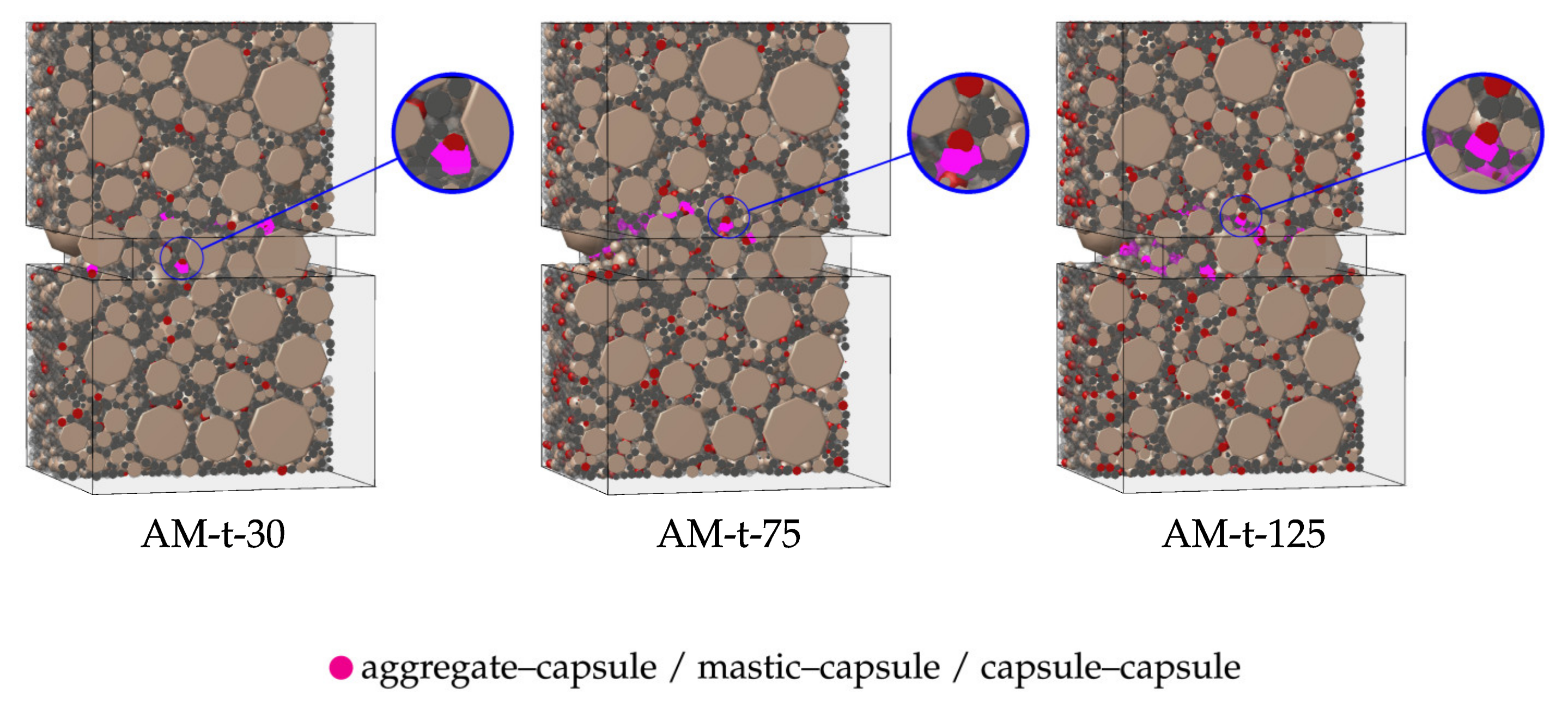
As previously discussed, most damaged contacts in the asphalt mixture specimens are localised in the vicinity of the notch tips, where stress concentration is most pronounced. However, it is essential to evaluate how the interactions involving capsules respond under monotonic tensile loading. Figure 12 provides detailed cross-sectional views of the asphalt mixtures containing capsules, offering further insight into this behaviour.
The results demonstrate that all contacts involving capsules—aggregate–capsule, mastic–capsule, and capsule–capsule—were fully damaged (i.e., reached a damage factor D = 100%) during the simulations. These failed contacts were located exclusively within the notch-tip region, indicating that damage to capsule-related contacts occur only under critical stress conditions where crack initiation and propagation are concentrated.
This outcome supports the primary design principle of using capsules in asphalt mixtures: they should remain intact under normal loading conditions and only become active in the presence of existing damage. The localisation of damaged capsule contacts near the notch tip also implies that, in scenarios where rejuvenator release is modelled, healing would likely occur precisely in the regions where it is most needed—where micro-cracks form and merge into macro-cracks. Thus, the presence of capsules in these high-damage zones can be strategically advantageous for fracture healing in asphalt pavements.

6. Modelling Limitations and Future Developments

To address some of the modelling limitations of this study, experimental and subsequently numerical validations have been planned. Ongoing studies are being conducted to extend the proposed methodology to a broader temperature and frequency ranges. In addition, future studies will include controlled experimental work to further validate the simulation of rejuvenator release and healing mechanisms. Modelling capsule breakage and the subsequent diffusion of rejuvenators will provide a more comprehensive understanding of self-healing efficiency.
A key contribution of this work is the proposed methodology for calibrating capsule parameters and evaluating their effects on the mechanical properties of asphalt mixtures. This approach can be readily extended to capsules with different mechanical properties and sizes. The proposed developments will be essential for optimising capsule design and dosage, ensuring an effective balance between mechanical performance and healing capacity.
Additional work, both numerical and experimental, is still required to demonstrate that asphalt mixtures containing encapsulated rejuvenators provide cost-effective and durable road pavement structures. In addition, it should be noted that the rejuvenators used in this technology should be bio-based and exhibit low toxicity to minimise environmental impact and associated risks.

7. Conclusions

The presented study contributes to the development of resilient and sustainable pavement solutions by providing key insights into the mechanical behaviour of self-healing asphalt mixtures. This study adopted the VirtualPM3DLab DEM-based model to assess the isolated mechanical effect of capsule incorporation into asphalt mixtures. The research focused on analysing the stiffness and tensile strength of mixtures through virtual tension–compression cyclic and monotonic tensile tests, considering realistic air void content and notched specimens. The influence of different capsule contents, based on commonly adopted values in experimental tests (0.30, 0.75, and 1.25 wt.%), as well as a parametric study on the calibrated capsule continuum equivalent Young’s modulus, were evaluated. The main findings are summarised below:
  • The three-dimensional DEM model effectively captured the behaviour of asphalt mixtures with capsules under different loading conditions and provided detailed insight into contact interactions and damage evolution.
  • The addition of capsules led to a progressive reduction in stiffness modulus. On average, reductions of 4.3%, 8.7%, and 12.3% were verified for capsule contents of 0.30, 0.75, and 1.25 wt.%, respectively. The phase angle, however, remained unaffected across all frequencies and capsule ratios.
  • The capsule continuum equivalent Young’s modulus, within the studied range (half and double of the calibrated value), had minimal influence on the overall rheological response. The most critical parameter affecting asphalt mixture stiffness was the capsule content, rather than the capsule stiffness itself.
  • Under tensile loading, the presence of capsules reduced the peak tensile strength (up to 12.4% for the highest capsule content), but did not significantly affect the stress–strain and damage evolution of the specimens. Damage was highly localised around the notch tips, and the trends remained consistent among all capsule contents.
  • Contacts involving capsules remained intact during early and intermediate loading stages and only fractured during the final damage stage, suggesting a delayed activation consistent with the design of healing systems. All these damaged contacts were localised within the notch-tip region, showing that simulations considering the rejuvenator effect would possibly influence the recovery of damaged asphalt mixtures.
  • Capsules themselves have limited mechanical influence, particularly on damage evolution. The main mechanical benefit expected from their use is associated with the rejuvenator release mechanism.
  • The numerical findings suggest that capsule contents of up to 0.75 wt.% can be incorporated without significant compromise to mechanical performance. Higher contents should be applied with caution due to the additional effect of rejuvenator in self-healing applications.
The proposed methodology and main findings are essential for optimising capsule content, not compromising the balance between mechanical performance and the desired healing capacity.

Author Contributions

Conceptualisation, N.M.A. and R.M.; methodology, G.C., N.M.A. and R.M.; software, G.C. and N.M.A.; validation, G.C.; investigation, G.C. and N.M.A.; writing—original draft preparation, G.C.; writing—review and editing, N.M.A. and R.M.; visualisation, G.C.; supervision, N.M.A. and R.M. All authors have read and agreed to the published version of the manuscript.

Funding

This work is part of the research activity of the third author carried out at Civil Engineering Research and Innovation for Sustainability (CERIS) and has been funded by Fundação para a Ciência e a Tecnologia (FCT) in the framework of project UIDB/04625/2025.

Data Availability Statement

The original contributions presented in the study are included in the article. Further inquiries can be directed to the corresponding author.

Conflicts of Interest

The authors declared no potential conflicts of interest concerning the research, authorship, and publication of this article.

References

  1. Wang, H.; Buttlar, W.G. Three-Dimensional Micromechanical Pavement Model Development for the Study of Block Cracking. Constr. Build. Mater. 2019, 206, 35–45. [Google Scholar] [CrossRef]
  2. Li, Y.; Feng, J.; Yang, F.; Wu, S.; Liu, Q.; Bai, T.; Liu, Z.; Li, C.; Gu, D.; Chen, A.; et al. Gradient Aging Behaviors of Asphalt Aged by Ultraviolet Lights with Various Intensities. Constr. Build. Mater. 2021, 295, 123618. [Google Scholar] [CrossRef]
  3. Gao, L.; Zhang, Y.; Liu, Y.; Wang, Z.; Ji, X. Study on the Cracking Behavior of Asphalt Mixture by Discrete Element Modeling with Real Aggregate Morphology. Constr. Build. Mater. 2023, 368, 130406. [Google Scholar] [CrossRef]
  4. Zhang, L.; Hoff, I.; Zhang, X.; Yang, C. Investigation of the Self-Healing and Rejuvenating Properties of Aged Asphalt Mixture Containing Multi-Cavity Ca-Alginate Capsules. Constr. Build. Mater. 2022, 361, 129685. [Google Scholar] [CrossRef]
  5. Wan, P.; Wu, S.; Liu, Q.; Xu, H.; Wang, H.; Peng, Z.; Rao, W.; Zou, Y.; Zhao, Z.; Chen, S. Self-Healing Properties of Asphalt Concrete Containing Responsive Calcium Alginate/Nano-Fe3O4 Composite Capsules via Microwave Irradiation. Constr. Build. Mater. 2021, 310, 125258. [Google Scholar] [CrossRef]
  6. Xu, X.; Yuan, L.; Cong, P.; Wang, Z.; Zhou, X.; Wang, J.; Liu, J. Self-Healing Microcapsule Properties Improvement Technology: Key Challenges and Solutions for Application in Asphalt Materials. Constr. Build. Mater. 2024, 439, 137298. [Google Scholar] [CrossRef]
  7. Li, Z.; Wang, H.; Wan, P.; Liu, Q.; Xu, S.; Jiang, J.; Fan, L.; Tu, L. Healing Evaluation of Asphalt Mixtures with Polymer Capsules Containing Rejuvenator under Different Water Solutions. Sustainability 2023, 15, 15258. [Google Scholar] [CrossRef]
  8. Norambuena-Contreras, J.; Yalcin, E.; Garcia, A.; Al-Mansoori, T.; Yilmaz, M.; Hudson-Griffiths, R. Effect of Mixing and Ageing on the Mechanical and Self-Healing Properties of Asphalt Mixtures Containing Polymeric Capsules. Constr. Build. Mater. 2018, 175, 254–266. [Google Scholar] [CrossRef]
  9. Ding, X.; Cui, Y.; Ma, T.; Ye, F. Multiscale-Mechanical Analysis on Self-Healing Microcapsules under Asphalt Pavement. Constr. Build. Mater. 2024, 443, 137670. [Google Scholar] [CrossRef]
  10. Bao, S.; Liu, Q.; Li, H.; Zhang, L.; Maria Barbieri, D. Investigation of the Release and Self-Healing Properties of Calcium Alginate Capsules in Asphalt Concrete under Cyclic Compression Loading. J. Mater. Civ. Eng. 2021, 33, 04020401. [Google Scholar] [CrossRef]
  11. Sun, D.; Hu, J.; Zhu, X. Size Optimization and Self-Healing Evaluation of Microcapsules in Asphalt Binder. Colloid Polym. Sci. 2015, 293, 3505–3516. [Google Scholar] [CrossRef]
  12. Foroutan Mirhosseini, A.; Tahami, S.A.; Hoff, I.; Dessouky, S.; Ho, C.-H. Performance Evaluation of Asphalt Mixtures Containing High-RAP Binder Content and Bio-Oil Rejuvenator. Constr. Build. Mater. 2019, 227, 116465. [Google Scholar] [CrossRef]
  13. Garcia, A.; Jelfs, J.; Austin, C.J. Internal Asphalt Mixture Rejuvenation Using Capsules. Constr. Build. Mater. 2015, 101, 309–316. [Google Scholar] [CrossRef]
  14. Ozdemir, A.M.; Yilmaz, M.; Yalcin, E.; Kok, B.V.; Norambuena-Contreras, J.; Garcia, A. Effects of Capsules Containing Waste Oils on the Mechanical Properties of Hot Mix Asphalt: Experimental Approach. J. Mater. Civ. Eng. 2021, 33, 04021242. [Google Scholar] [CrossRef]
  15. Aguirre, M.A.; Hassan, M.M.; Shirzad, S.; Mohammad, L.N.; Cooper, S.; Negulescu, I.I. Laboratory Testing of Self-Healing Microcapsules in Asphalt Mixtures Prepared with Recycled Asphalt Shingles. J. Mater. Civ. Eng. 2017, 29, 04017099. [Google Scholar] [CrossRef]
  16. Kargari, A.; Arabani, M.; Mirabdolazimi, S.M. Effect of Palm Oil Capsules on the Self-Healing Properties of Aged and Unaged Asphalt Mixtures Gained by Resting Period and Microwave Heating. Constr. Build. Mater. 2022, 316, 125901. [Google Scholar] [CrossRef]
  17. Ruiz-Riancho, N.; Garcia, A.; Grossegger, D.; Saadoon, T.; Hudson-Griffiths, R. Properties of Ca-Alginate Capsules to Maximise Asphalt Self-Healing Properties. Constr. Build. Mater. 2021, 284, 122728. [Google Scholar] [CrossRef]
  18. Garcia, A.; Austin, C.J.; Jelfs, J. Mechanical Properties of Asphalt Mixture Containing Sunflower Oil Capsules. J. Clean. Prod. 2016, 118, 124–132. [Google Scholar] [CrossRef]
  19. Al-Mansoori, T.; Micaelo, R.; Artamendi, I.; Norambuena-Contreras, J.; Garcia, A. Microcapsules for Self-Healing of Asphalt Mixture without Compromising Mechanical Performance. Constr. Build. Mater. 2017, 155, 1091–1100. [Google Scholar] [CrossRef]
  20. Sun, D.; Li, B.; Ye, F.; Zhu, X.; Lu, T.; Tian, Y. Fatigue Behavior of Microcapsule-Induced Self-Healing Asphalt Concrete. J. Clean. Prod. 2018, 188, 466–476. [Google Scholar] [CrossRef]
  21. Quezada, J.C.; Chazallon, C. Discrete Element Modelling of Hot Mix Asphalt Complex Modulus Using Realistic Aggregate Shapes. Road Mater. Pavement Des. 2022, 23, 178–195. [Google Scholar] [CrossRef]
  22. Zhang, Y.; Ma, T.; Ling, M.; Zhang, D.; Huang, X. Predicting Dynamic Shear Modulus of Asphalt Mastics Using Discretized-Element Simulation and Reinforcement Mechanisms. J. Mater. Civ. Eng. 2019, 31, 04019163. [Google Scholar] [CrossRef]
  23. Zhu, X.; Yu, H.; Qian, G.; Yao, D.; Dai, W.; Zhang, H.; Li, J.; Zhong, H. Evaluation of Asphalt Mixture Micromechanical Behavior Evolution in the Failure Process Based on Discrete Element Method. Case Stud. Constr. Mater. 2023, 18, e01773. [Google Scholar] [CrossRef]
  24. Liu, J.; Wang, Y.; Wang, S.; Liu, Q.; Yu, B.; Wang, Q. Use of X-Ray Computed Tomography to Evaluate the Gradual Behaviour of Air Voids in Asphalt Mixtures during Permanent Deformation. Int. J. Pavement Eng. 2023, 24, 2134570. [Google Scholar] [CrossRef]
  25. Peng, Y.; Gao, H. Comparative Modelling of Indirect Tensile Strength of Asphalt Mixtures with and without Considering Air Void Characteristics. Int. J. Pavement Eng. 2021, 22, 1601–1610. [Google Scholar] [CrossRef]
  26. Câmara, G.; Micaelo, R.; Monteiro Azevedo, N. 3D DEM Model Simulation of Asphalt Mastics with Sunflower Oil. Comput. Part. Mech. 2023, 10, 1569–1586. [Google Scholar] [CrossRef]
  27. Yin, H.; Li, Y.; Huang, H. Mesoscopic Study on Mechanical Properties and Dynamic Damage Characteristics of Self-Healing Microcapsule. Comput. Part. Mech. 2024, 11, 197–209. [Google Scholar] [CrossRef]
  28. Zhang, H.; Quan, W.; Wang, R. Study on Crack Resistance of Self-Healing Microcapsules in Asphalt Pavement by Multi-Scale Method. PLoS ONE 2024, 19, e0300178. [Google Scholar] [CrossRef]
  29. Zhang, H.; Yao, T.; Li, C. Study on the Mechanical Behavior of Microcapsules during the Mixing Process of Asphalt Mixture. Constr. Build. Mater. 2024, 441, 137531. [Google Scholar] [CrossRef]
  30. Ge, H.; Quezada, J.C.; Le Houerou, V.; Chazallon, C.; Sha, A. From Macro to Micro: Investigation of Three-Dimensional Particle-Scale Responses of Asphalt Mixtures under Non-Uniform Rolling Tire Loads via Coupled FEM-DEM Simulations. Road Mater. Pavement Des. 2025, 1–30. [Google Scholar] [CrossRef]
  31. Hanna, J.; Elamin, A. Computational Fracture Modeling for Effects of Healed Crack Length and Interfacial Cohesive Properties in Self-Healing Concrete Using XFEM and Cohesive Surface Technique. Computation 2023, 11, 142. [Google Scholar] [CrossRef]
  32. Nian, T.; Ge, J.; Li, P.; Guo, R.; Li, J.; Wang, M. Improved Three-Dimensional Discrete Modeling Method and Anti-Cracking Properties of Asphalt Mixture. Constr. Build. Mater. 2022, 321, 126405. [Google Scholar] [CrossRef]
  33. Chen, X.; Ai, C.; Du, J.; He, H.; Huang, Y. Effect of Gradation Segregation on Low-Temperature Crack Resistance of Asphalt Pavement Using 3D DEM. Constr. Build. Mater. 2021, 274, 122060. [Google Scholar] [CrossRef]
  34. García, Á.; Schlangen, E.; van de Ven, M. Properties of Capsules Containing Rejuvenators for Their Use in Asphalt Concrete. Fuel 2011, 90, 583–591. [Google Scholar] [CrossRef]
  35. Câmara, G.; Azevedo, N.M.; Micaelo, R.; Silva, H. Generalised Kelvin Contact Models for DEM Modelling of Asphalt Mixtures. Int. J. Pavement Eng. 2023, 24, 2179625. [Google Scholar] [CrossRef]
  36. Câmara, G.; Micaelo, R.; Azevedo, N.M.; Silva, H. Incremental Viscoelastic Damage Contact Models for Asphalt Mixture Fracture Assessment. Infrastructures 2024, 9, 118. [Google Scholar] [CrossRef]
  37. Peng, C.; Wang, Z.; Zhu, C.; Kuang, D. 3D Reconstruction of Asphalt Mixture Based on 2D Images. Constr. Build. Mater. 2025, 462, 139938. [Google Scholar] [CrossRef]
  38. Du Plessis, A.; Boshoff, W.P. A Review of X-Ray Computed Tomography of Concrete and Asphalt Construction Materials. Constr. Build. Mater. 2019, 199, 637–651. [Google Scholar] [CrossRef]
  39. Liu, Y.; Gong, F.; You, Z.; Wang, H. Aggregate Morphological Characterization with 3D Optical Scanner versus X-Ray Computed Tomography. J. Mater. Civ. Eng. 2018, 30, 04017248. [Google Scholar] [CrossRef]
  40. Ding, X.; Liu, F.; Ma, T.; Xiao, B. Effects of Coarse Aggregate Morphology on Asphalt Mixture’s Flowability: Parametric and Prediction Study. Case Stud. Constr. Mater. 2024, 21, e03735. [Google Scholar] [CrossRef]
  41. Peng, Y.; Xu, Y.; Zhang, X.; Meng, H.; Lu, X. Investigation on the Effects of Asphalt Mixes and Their Combinations on Asphalt Mix Shear Strength by 3D Discrete Element Method. Int. J. Pavement Eng. 2023, 24, 2251078. [Google Scholar] [CrossRef]
  42. Azevedo, N.M.; Farinha, M.L.B.; Oliveira, S. Assessment of Contact Laws Accounting for Softening in 3D Rigid Concrete Particle Models. Buildings 2024, 14, 801. [Google Scholar] [CrossRef]
  43. Ma, T.; Zhang, D.; Zhang, Y.; Zhao, Y.; Huang, X. Effect of Air Voids on the High-Temperature Creep Behavior of Asphalt Mixture Based on Three-Dimensional Discrete Element Modeling. Mater. Des. 2016, 89, 304–313. [Google Scholar] [CrossRef]
  44. Chen, Y.; Ji, X.; Si, B.; Zhang, Z.; Shao, D.; Zhu, S.; He, S. Investigation on Self-Healing Performance of Asphalt Mixture Containing Microcapsules and Survival Behaviour of Microcapsules. Int. J. Pavement Eng. 2023, 24, 2165657. [Google Scholar] [CrossRef]
  45. Xu, S.; Tabaković, A.; Liu, X.; Schlangen, E. Calcium Alginate Capsules Encapsulating Rejuvenator as Healing System for Asphalt Mastic. Constr. Build. Mater. 2018, 169, 379–387. [Google Scholar] [CrossRef]
  46. Zhang, L.; Liu, Q.; Li, H.; Norambuena-Contreras, J.; Wu, S.; Bao, S.; Shu, B. Synthesis and Characterization of Multi-Cavity Ca-Alginate Capsules Used for Self-Healing in Asphalt Mixtures. Constr. Build. Mater. 2019, 211, 298–307. [Google Scholar] [CrossRef]
  47. Câmara, G.; Azevedo, N.M.; Micaelo, R. Impact of Rejuvenator-Modified Mastic on Asphalt Mixture Stiffness: Meso-Scale Discrete Element Method Approach. Buildings 2023, 13, 3023. [Google Scholar] [CrossRef]
  48. Gong, F.; Liu, Y.; Zhou, X.; You, Z. Lab Assessment and Discrete Element Modeling of Asphalt Mixture during Compaction with Elongated and Flat Coarse Aggregates. Constr. Build. Mater. 2018, 182, 573–579. [Google Scholar] [CrossRef]
  49. Xie, S.; Yi, J.; Wang, H.; Yang, S.-H.; Xu, M.; Feng, D. Mechanical Response Analysis of Transverse Crack Treatment of Asphalt Pavement Based on DEM. Int. J. Pavement Eng. 2022, 23, 2206–2226. [Google Scholar] [CrossRef]
  50. Zhou, M.; Cao, W. Mesoscopic Analysis of Fatigue Damage Development in Asphalt Mixture Based on Modified Burgers Contact Algorithm in Discrete Element Modeling. Materials 2024, 17, 2025. [Google Scholar] [CrossRef]
  51. Ren, J.; Sun, L. Generalized Maxwell Viscoelastic Contact Model-Based Discrete Element Method for Characterizing Low-Temperature Properties of Asphalt Concrete. J. Mater. Civ. Eng. 2016, 28, 04015122. [Google Scholar] [CrossRef]
  52. Sun, L.; Ren, J.; Zhang, S. Fracture Characteristics of Asphalt Concrete in Mixed-Loading Mode at Low-Temperature Based on Discrete-Element Method. J. Mater. Civ. Eng. 2018, 30, 04018321. [Google Scholar] [CrossRef]
  53. Ren, J.; Liu, Z.; Xue, J.; Xu, Y. Influence of the Mesoscopic Viscoelastic Contact Model on Characterizing the Rheological Behavior of Asphalt Concrete in the DEM Simulation. Adv. Civ. Eng. 2020, 2020, 5248267. [Google Scholar] [CrossRef]
  54. Liang, H.; Shi, L.; Wang, D.; Xiao, X.; Deng, K. Influence of Graded Coarse Aggregate Content and Specific Surface Area on the Fracture Properties of Asphalt Mixtures Based on Discrete Element Simulations and Indoor Tests. Constr. Build. Mater. 2021, 299, 123942. [Google Scholar] [CrossRef]
  55. Bai, X.; Wang, L. Study on Mesoscopic Model of Low-Temperature Cracking of Steel Slag Asphalt Mixture Based on Random Aggregate. Constr. Build. Mater. 2023, 364, 129974. [Google Scholar] [CrossRef]
  56. Shen, Z.; Xiao, Y.; Hou, K.; Chen, Y.; Meng, F. Investigating the Impact of Porous Steel Slag Aggregates on the Low-Temperature Crack Resistance of Asphalt Concrete. Constr. Build. Mater. 2024, 453, 138914. [Google Scholar] [CrossRef]
  57. Dan, H.-C.; Zhang, Z.; Chen, J.; Cao, W. Low-Temperature Fracture Characteristics of Asphalt Mixtures Using the Eccentric Single-Edge Notched Bend Test: A 3D Discrete Element Study. Constr. Build. Mater. 2022, 344, 128182. [Google Scholar] [CrossRef]
  58. Micaelo, R.; Freire, A.C.; Pereira, G. Asphalt Self-Healing with Encapsulated Rejuvenators: Effect of Calcium-Alginate Capsules on Stiffness, Fatigue and Rutting Properties. Mater. Struct. 2020, 53, 20. [Google Scholar] [CrossRef]
  59. Tabaković, A.; Braak, D.; Van Gerwen, M.; Copuroglu, O.; Post, W.; Garcia, S.J.; Schlangen, E. The Compartmented Alginate Fibres Optimisation for Bitumen Rejuvenator Encapsulation. J. Traffic Transp. Eng. Engl. Ed. 2017, 4, 347–359. [Google Scholar] [CrossRef]
  60. Derakhshan, M.; Ameri, M.; Aliha, M.; Shaker, H. Laboratory Evaluation of Self-Healing Capability of Warm-Mix Asphalt Containing Calcium Alginate Capsules under Aging Conditions. J. Mater. Civ. Eng. 2025, 37, 04024456. [Google Scholar] [CrossRef]
  61. Wang, H.; Yuan, M.; Wu, J.; Wan, P.; Liu, Q. Self-Healing Properties of Asphalt Concrete with Calcium Alginate Capsules Containing Different Healing Agents. Materials 2022, 15, 5555. [Google Scholar] [CrossRef]
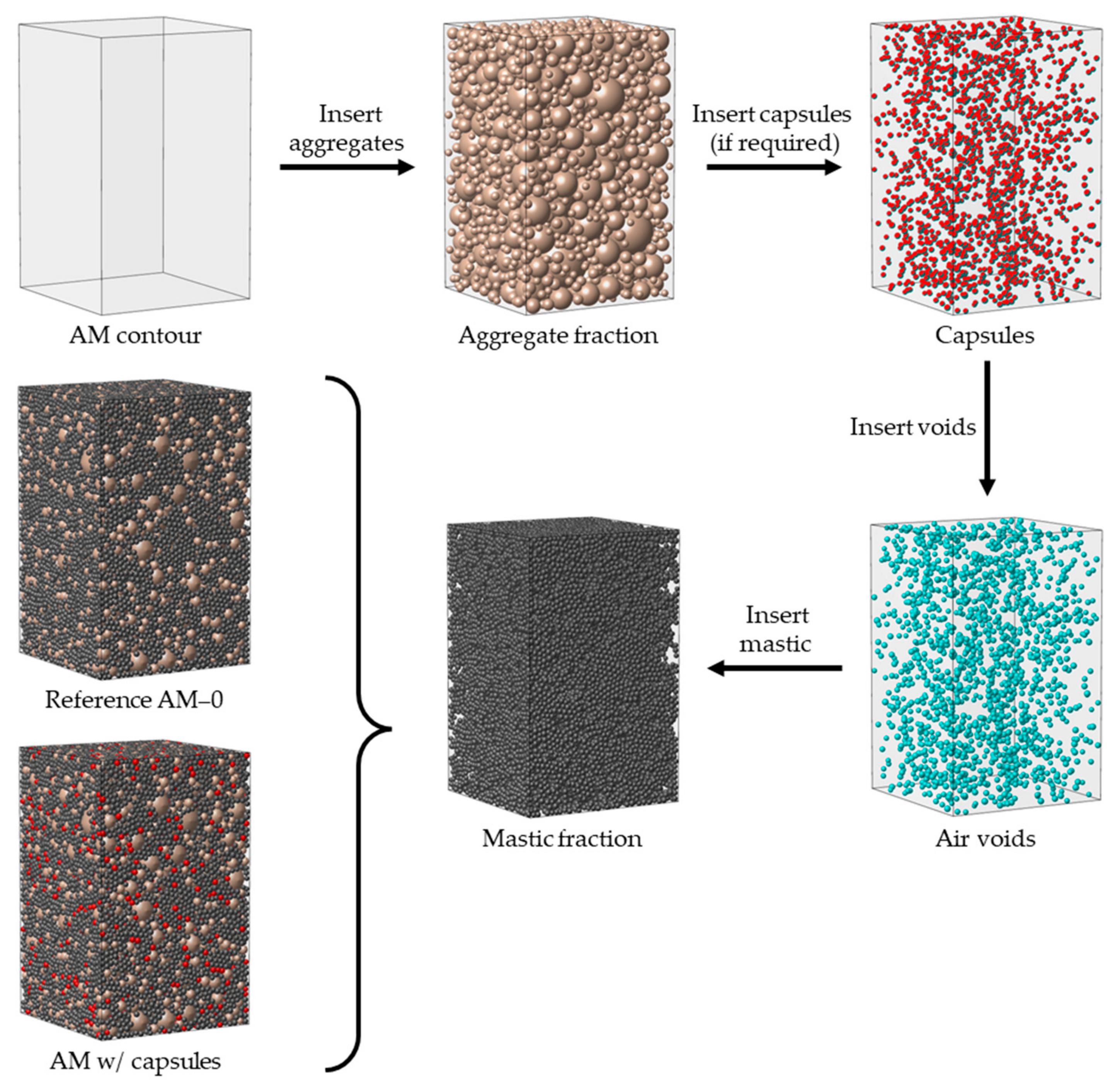
Figure 1. Asphalt mixture for tension–compression sinusoidal simulations: reference AM–0 and with capsules.
Sustainability 17 07502 g001
Figure 2. Asphalt mixture for tensile strength simulations: (a) reference AM–t–0; (b) AM–t with capsules; (c) AM–t, capsules only shown.
Sustainability 17 07502 g002
Figure 3. Contact model representation: viscoelastic model—(1) aggregate–mastic, (2) mastic–capsule, and (6) mastic–mastic; Elastic model—(3) aggregate–capsule, (4) aggregate–aggregate, and (5) capsule–capsule.
Sustainability 17 07502 g003
Figure 4. Damage model representation: (a) force-displacement; (b) damage evolution.
Sustainability 17 07502 g004
Figure 5. Capsule uniaxial compression calibration: (a) test configuration; (b) experimental vs. DEM results.
Sustainability 17 07502 g005
Figure 6. Effect of capsules on the stiffness behaviour of asphalt mixtures under dynamic loading.
Sustainability 17 07502 g006
Figure 7. Influence of capsule calibration on AM models: 1/2 modulus.
Sustainability 17 07502 g007
Figure 8. Influence of capsule calibration on AM models: 2x modulus.
Sustainability 17 07502 g008
Figure 9. Tensile loading test results: tensile stress and damage evolution in the overall and mid-section of and of the AM–t models.
Sustainability 17 07502 g009
Figure 10. Contact damage evolution in the AM–t assemblies during simulations.
Sustainability 17 07502 g010
Figure 11. AM-t models: damage path under tensile loading—line thickness proportional to contact damage.
Sustainability 17 07502 g011aSustainability 17 07502 g011b
Figure 12. Cross-sectional views of AM-t specimens: damage contact path of capsules—line thickness proportional to contact damage.
Sustainability 17 07502 g012
Table 1. Mineral aggregate gradation and corresponding generated aggregate particles for reference specimens.
Mineral AggregatesMastic
Sieve size [mm]19.012.59.54.752.0>2.0
AM–0
Particles retained-1328288218422,861
Volume [mm3]-26,286.821,400.240,913.329,256.474,551.0
AM–t–0
Particles retained-1326282211722,168
Volume [mm3]-26,286.819,961.440,122.628,387.272,285.4
Table 2. Total number of contacts by contact type in the AM and AM–t models.
Asphalt Mixture Model: AM (AM–t)
Interaction typeAM–0 (AM–t–0)AM–30 (AM–t–30)AM–75 (AM–t–75)AM–125 (AM–t–125)
Aggregate–aggregate4670 (4499)4667 (4493)4738 (4452)4670 (4499)
Aggregate–mastic55,108 (53,048)53,486 (51,522)51,710 (49,774)50,235 (48,354)
Mastic–mastic78,795 (76,073)73,689 (71,044)67,312 (65,032)62,497 (60,360)
Aggregate–capsule1284 (1236)2961 (2841)4873 (4694)
Mastic–capsule3877 (3730)9428 (9089)15,763 (15,203)
Capsule–capsule23 (21)143 (137)535 (510)
Aggregate–wall164 (164)163 (163)157 (157)164 (164)
Mastic–wall1373 (1373)1356 (1356)1299 (1299)1257 (1257)
Capsule-wall28 (28)86 (86)116 (116)
Table 3. Calibrated parameters of the macroscopic GK model [35].
Chain NumberGK Macroscopic ComponentValue
1 E 1 [kPa] 8.95 × 10 6
C 1 [kPa∙s] 3.80 × 10 5
2 E 2 5.70 × 10 6
C 2 1.60 × 10 6
3 E 3 1.11 × 10 6
C 3 4.31 × 10 7
Maxwell components E m [kPa] 1.12 × 10 7
C m [kPa∙s] 2.52 × 10 6
Table 4. Contact strength parameters for the GK–Bilinear model [36].
Contact ParameterCalibrated Value
Maximum contact tensile stress [MPa]6.12
Maximum contact cohesion stress [MPa]24.48
Contact fracture energy in mode I [N/mm]0.35
Contact fracture energy in mode II [N/mm]56.44
Table 5. Stiffness modulus behaviour results for asphalt mixtures.
Asphalt MixtureVariation in Stiffness (%)
Min (Max)
Difference in Phase Angle (°)
Min (Max)
AM–304.3 (4.4)0.02 (−0.11)
AM–758.4 (8.9)−0.11 (−0.31)
AM–12512.1 (12.4)−0.10 (−0.31)
Disclaimer/Publisher’s Note: The statements, opinions and data contained in all publications are solely those of the individual author(s) and contributor(s) and not of MDPI and/or the editor(s). MDPI and/or the editor(s) disclaim responsibility for any injury to people or property resulting from any ideas, methods, instructions or products referred to in the content.