1. Introduction
In terms of their strength properties, specific gravity, and other properties, composite materials surpass traditional metal materials and are widely used in the manufacture of structural elements in industry. At the same time, it is known that ensuring the reliability of composite structural elements containing holes is complicated. This is due to the fact that the stress concentration factors (SCFs) in the compositions as a rule are significantly higher than the corresponding values for homogeneous isotropic materials.
The standard method of ensuring the strength and reliability of structural elements with a hole by increasing the thickness of all elements is inefficient, since the stress concentration area is relatively small. This method ensures a decrease in the material consumption of products and accordingly their cost. In accordance with the concept of sustainable development, this conserves economic resources in terms of the life cycle of products [
1]. Operating aircraft with increased weight leads to additional fuel cost, which is also irrational within the framework of sustainable development [
2].
The need to reduce stress concentrations is often accompanied by deterioration in structural design. For example, in the 1950s, airplanes (including the world’s first jet-powered passenger airliner, the de Havilland Comet) were built with rectangular windows, which were more familiar to passengers. However, airplane accidents caused by cracks initiating at the window corners forced designers to return to oval-shaped windows.
To reduce stress concentration in metal structural elements, holes are reinforced using internal rings or overlay plates. Methods for selecting the optimal methods of such reinforcement in isotropic materials are quite fully developed in the literature and presented in the well-known reference books of Peterson [
3] and Savin [
4], etc. This method of strengthening requires a slight increase in the material consumption and weight of the structure, and therefore its use is consistent with the main criteria of the concept of sustainable development.
The methods required for local reinforcement of components using composite materials are relatively simple (they are carried out without welding). Therefore, this method is widely used in aircraft structure repair when stress concentrators are detected by gluing high-strength composite materials [
5,
6,
7,
8]. Composite structures with defects are repaired by gluing composite patches [
9,
10,
11,
12]. It has been established that repair efficiency is dependent on the mechanical properties, shape, and dimensions of the reinforcing overlays [
6,
7,
8,
13,
14,
15].
Studies on defects in the area of overlays detected during the gluing process were carried out in [
16,
17]. The types of adhesives and gluing methods have a significant impact on the quality of repair work [
18].
The approaches to repair work considered above enable one to increase the strength of composite structural elements with holes by reinforcing the hole boundaries with rings or gluing composite overlays around the hole. To select the materials, shape, dimensions and thickness of the overlay, it is necessary to develop a method for determining the stresses of nearby holes, taking into account the shape, thickness, and mechanical properties of the reinforcing elements. For this purpose, regions with glued overlays of elastic inclusions from another material, which can be layered, were modeled. Then, the determination of stresses in a plate with a reinforced hole was reduced to the solving of an anisotropic elasticity problem with elastic inclusions.
Methods for determining stresses near inclusions have been studied quite thoroughly for isotropic materials [
19,
20,
21]. Problems of the Eshelby type, in which elastic inclusions are also considered, were investigated in [
22,
23,
24].
The problem of determining the stresses near an elastic inclusion of elliptical shape in a composite plate, taking into account its anisotropic mechanical properties, was first considered in [
25]. For inclusions of more complex shapes, numerical methods are used to study the stresses, which in particular are based on the boundary element method [
26,
27,
28,
29].
The calculation of stresses near the inclusion is rather complicated, as it is based on solving a system of four integral equations. In the case of reinforced holes, it is necessary to simultaneously satisfy the boundary conditions on the interfaces of elastic inclusions and at the boundary of holes. Therefore, the problem of studying stresses for such classes of problems remains insufficiently studied.
In [
30,
31], singular integral equations for anisotropic plates with rigid and elastic inclusions are written on the basis of the established interdependencies between Lekhnitskii potentials, stresses, and displacements and the Cauchy theorem. In [
31], based on the constructed singular integral equations, an effective numerical approach to the study of stresses near elastic inclusions of various shapes is developed.
An approach to constructing modified integral equations using Green’s solutions, which allows the automatic satisfying of boundary conditions at the boundaries of holes, has been developed in the literature [
32,
33]. Similar integral equations for composite plates with anisotropic elastic inclusions and holes are contained in this article. When studying stresses in a plate with an elastic inclusion, an elliptical hole, and an additional rectilinear boundary, modified integral equations were obtained using two of Green’s solutions. The resulting system of four integral equations includes only the unknowns at the boundaries of inclusions, which significantly simplifies the numerical solution of the equations. Based on these equations, studies to select the materials, thickness, and shape of reinforcement were conducted.
In order to confirm the reliability of the obtained results, stress calculations were performed for isotropic (metal) plates with reinforced holes using the three-dimensional theory of elasticity.
The performed by us this research was aimed at increasing the strength of composite structures with holes and local overlays to make possible reductions in material consumption during the manufacturing of structures, decrease operating fuel costs (due to weight reduction), and at the same time increase the reliability of their operation. Therefore, this method complies with the basic conceptual standards of sustainable development.
The aim of this research was to develop a method for optimizing the geometry and mechanical properties of overlays to reduce stress concentration near holes in composite structures. To achieve this goal, the following tasks were formulated: construction of a model for calculating stresses based on the anisotropic theory of elasticity; development of the method of integral equations for studying stress distribution; study of the effectiveness of the method of gluing different types of overlays to increase strength; and verification of the accuracy of the constructed model using three-dimensional stress analysis.
2. Materials and Methods
2.1. Materials
In industry, various types of composite materials with wide ranges of elastic properties are used. When calculating stresses, elastic properties are used, which are anisotropic and are determined experimentally for selected materials. The distribution of stresses in anisotropic materials significantly depends on the degree of anisotropy, which is taken as the ratio of elastic moduli.
In this work, stress studies were carried out for three composite materials, whose elastic constants are given in
Table 1 [
34]. Here, glass–epoxy is a typical material with a small degree of anisotropy, and boron–epoxy and graphite–epoxy correspond to materials with medium and high degrees of anisotropy, respectively.
2.2. Methods
Statement of the problem. An anisotropic plate with an elastic inclusion is considered. In the following, all quantities related to the inclusion and the plate (matrix) will be denoted index 1 and index 2, respectively, while the area occupied by the matrix is denoted and inclusion . It is assumed that the inclusion and the matrix are weakened by load-free holes, the boundaries of which are contours loaded with concentrated forces , which are attached in p. , the matrix is loaded at infinity and the thicknesses of the inclusion and the matrix are equal— and . The curve, denoted , is where the inclusion and the matrix are in contact.
When considering the area on its boundary contour , a positive direction of the bypass chosen, in which this region is located on the left. The arc coordinate on this contour is denoted (and ), the stress vector , and the displacement vector , .
The general solution is written in terms of Lekhnitskii complex potentials
, where
,
are positive imaginary roots that are a part of characteristic equations [
25], e.g.:
where
are elastic constants in Hooke’s law for areas and
.
Basic ratios. The introduced vectors of stresses and displacements on the curve
are determined by the complex Lekhnitskii potentials
in formulas [
25]:
where
,
.
From these relations, the potentials on the contour
can be determined [
30,
31]:
where:
The integral representation of the solution for the particular case where the inclusion and the matrix are continuous is given in [
30]. Assuming that there is an ideal mechanical contact between the inclusion and the matrix, using Cauchy’s theorem, it is written in the form:
where
and integration is performed according to the above directions.
Here, are complex potentials for inclusion of infinite dimensions (at k = 1) and matrices with inclusion of zero dimensions (at k = 2) due to the loads applied to them.
Integral equations based on Green’s solutions. Considered the case where holes are placed in the inclusion and matrix. The integral equations are written using Green’s solutions. To achieve this, the potentials of Lekhnitskii
are constructed for an infinite plate with a load-free hole bounded by a contour
at elastic constants
, which have poles at arbitrary points
:
where
are complex constants and
.
The potentials with poles (4) are defined at , where T is a point with coordinates denoted by , j = 1…4.
Then, the representation (3) is modified as follows [
31].
are complex potentials for infinite plates with a load-free hole bounded by a contour , which correspond to the loads applied to the inclusion (at k = 1) and the matrix (k = 2).
To construct integral equations, the vectors of stresses and displacements on the contour
are defined by the formulas in Equation (1) through potentials (Equation (5)). Using Plemelj–Sokhotski formulas and the results of [
30], the following equations are obtained at
:
where the waves above the potentials indicate that the singular integrals are understood in the sense of Cauchy principal values.
The formulas in (6) can be rewritten in the form:
where
is a point with coordinates
,
,
and
are derivatives of the displacement vector
and stress vectors
on the arc
at point
, which correspond to the potentials
, at
, and are calculated by the formulas in Equation (1).
Quantities and are derivatives of the displacement vector and the stress vector on the curve at the point , which correspond to the potentials .
Taking into account that on the contour
,
it follows from the first formula in Equation (7):
where
.
The equation is obtained as follows:
where:
Similarly, the following is obtained:
where:
Numerical solution of integral equations. Consider the case where the integration contour is given parametrically in the form
[
31,
33]. Then, using the quadrature formulas of trapezoids for regular and singular integrals, which are included in Equations (7) and (9), a system of algebraic equations is obtained:
where
is a point with coordinates
and
is a point with coordinates
.
, , , .
Note that the quadrature formulas used for periodic functions (which arise in our integrals) are of the Gaussian type.
Based on the quantities obtained from this system, using the formulas in Equation (2), the Lekhnitskii potentials can be determined, and then the stresses in the matrix and the inclusions on the curve . The stresses at internal points are determined by the formulas in Equation (5).
3. Results and Discussion
Holes reinforced with homogeneous elastic rings. An anisotropic graphite–epoxy plate with a ring inclusion
, which is stretched by forces
p along the
Y-axis, is considered. The integral equations are constructed on the basis of Green’s solution for an anisotropic plate with an elliptical hole of radius a [
32]; therefore, the boundary conditions for the hole in the inclusion are satisfied identically. The calculated relative stress for an isotropic ring at Poisson’s ratio
and elastic moduli
and
depending on the ratio
R/
a are shown in
Figure 1 and
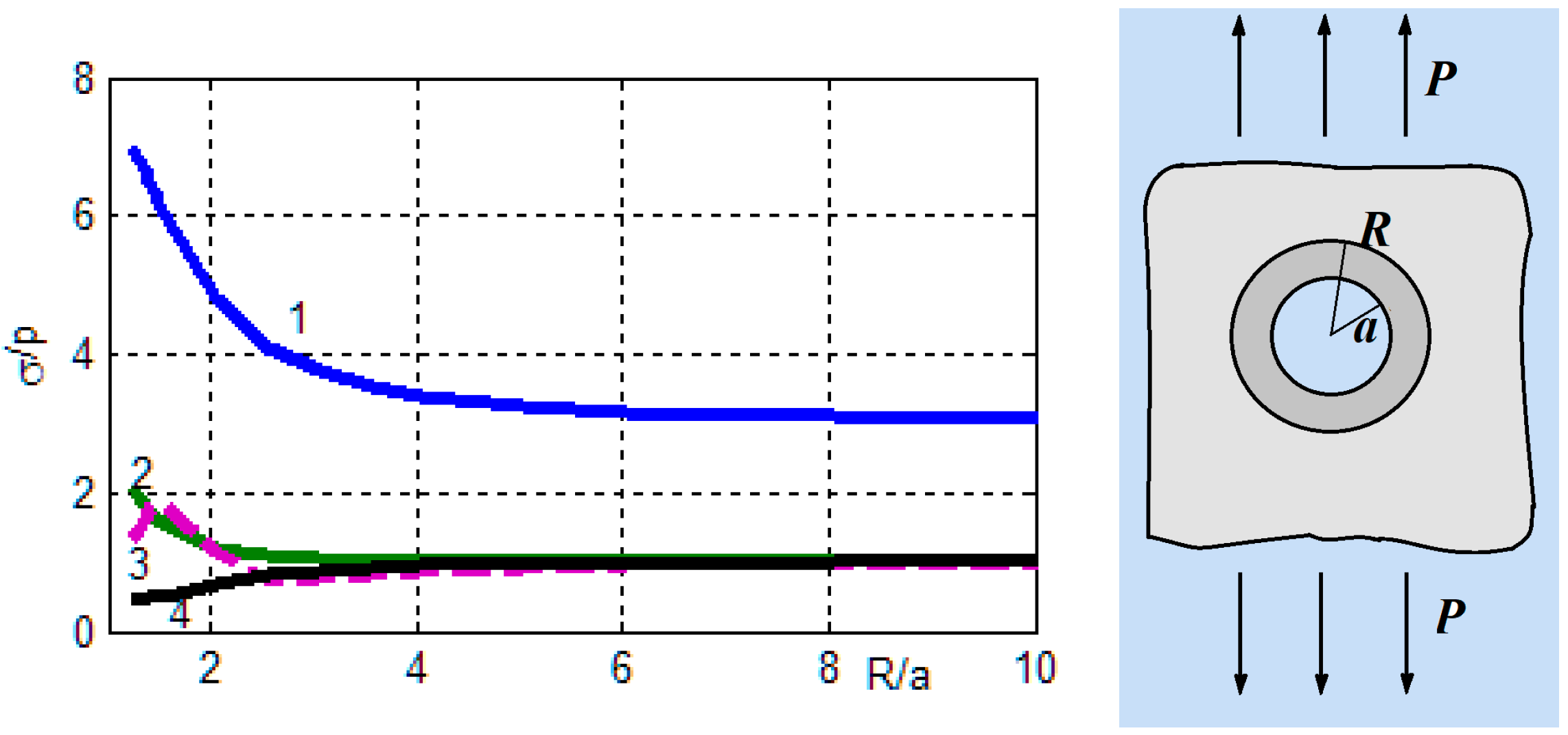
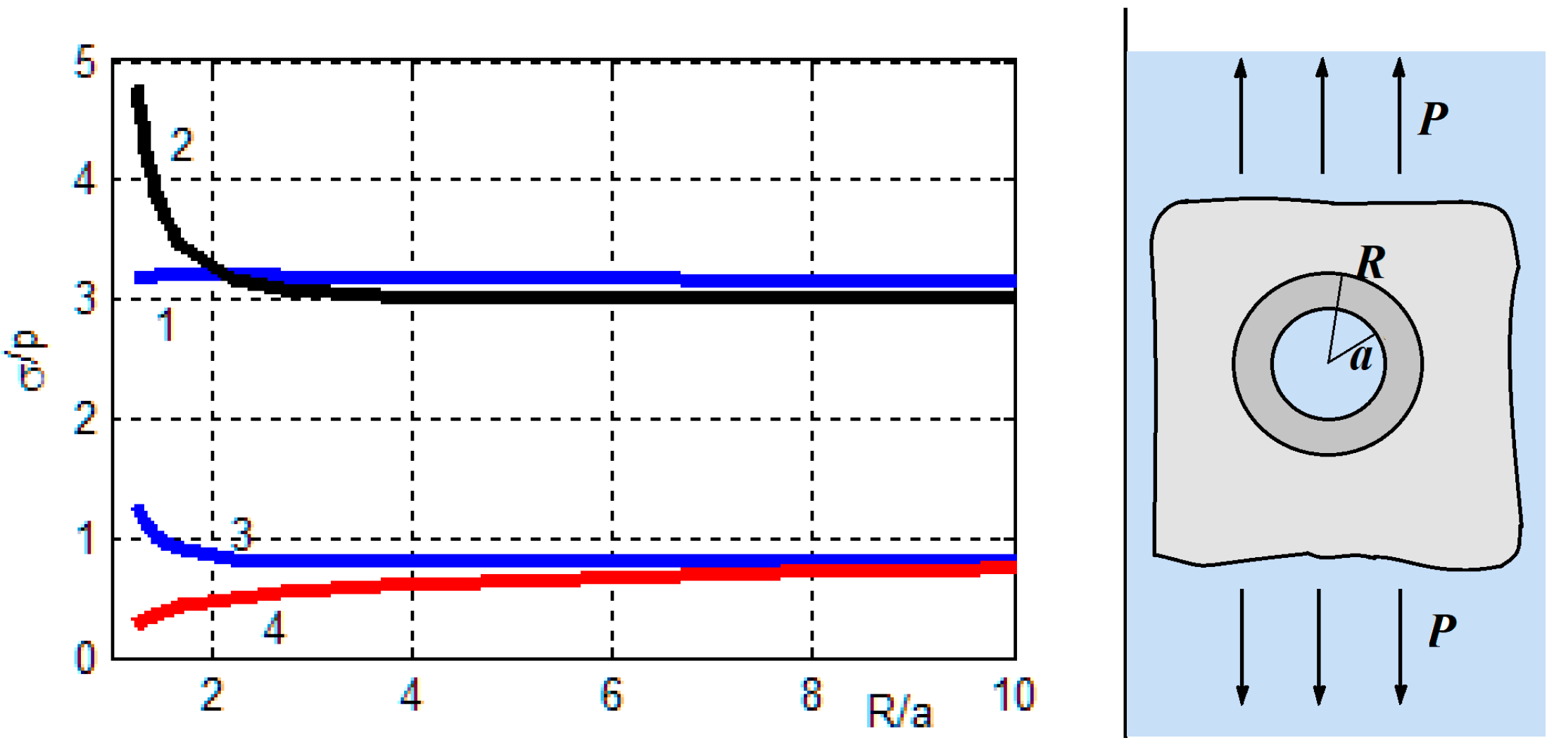
Figure 2. Here, curve 1 corresponds to the stress concentration factor (SCF) at the hole boundary in the inclusion, curves 2 and 3 show the relative maximum hoop stresses (
) at the interface in the plate and the inclusion, and curve 4 corresponds to relative normal maximum stresses at the junction.
Similar results are shown when the inclusion is made of glass–epoxy material.
It should be noted that for a homogeneous graphite–epoxy plate with a circular hole, the SCF = 10.59. Based on the data in
Figure 1,
Figure 2 and
Figure 3, it follows that for a composite plate, the stresses near the hole are reduced when reinforced with a ring of lower stiffness than that of the plate. The stress concentration is especially reduced when the hole is reinforced with fiberglass, the strength properties of which are close to the properties of the plate itself. A composite plate reinforced with a steel ring, the modulus of elasticity of which is
(which is close to the maximum modulus of elasticity of the matrix), also significantly reduced the SCF. For the considered cases of isotropic inclusion, the stresses at the hole boundary are greater than at the junction of the inclusion and the matrix at arbitrary values of the inclusion sizes, while for anisotropic inclusion (
Figure 3) at
, the maxima are the hoop stresses at the junction of the materials in the inclusion.
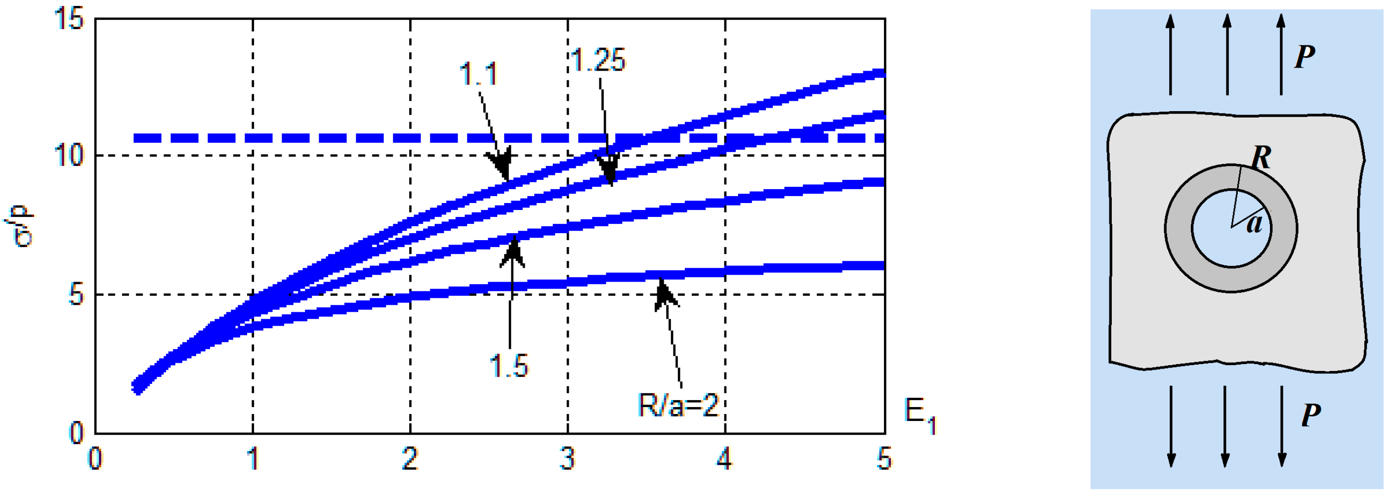
The stress is calculated depending on the modulus of elasticity of the isotropic inclusion. The value of the SCF at the hole boundary at different values of the ratio
is shown in
Figure 4, where it is marked
. The dashed line shows the SCF for the plate without inclusion.
In
Figure 4, it can be seen that the SCF monotonically increases with increasing inclusion stiffness at all sizes of radius
R, and with increasing inclusion sizes, the SCF decreases.
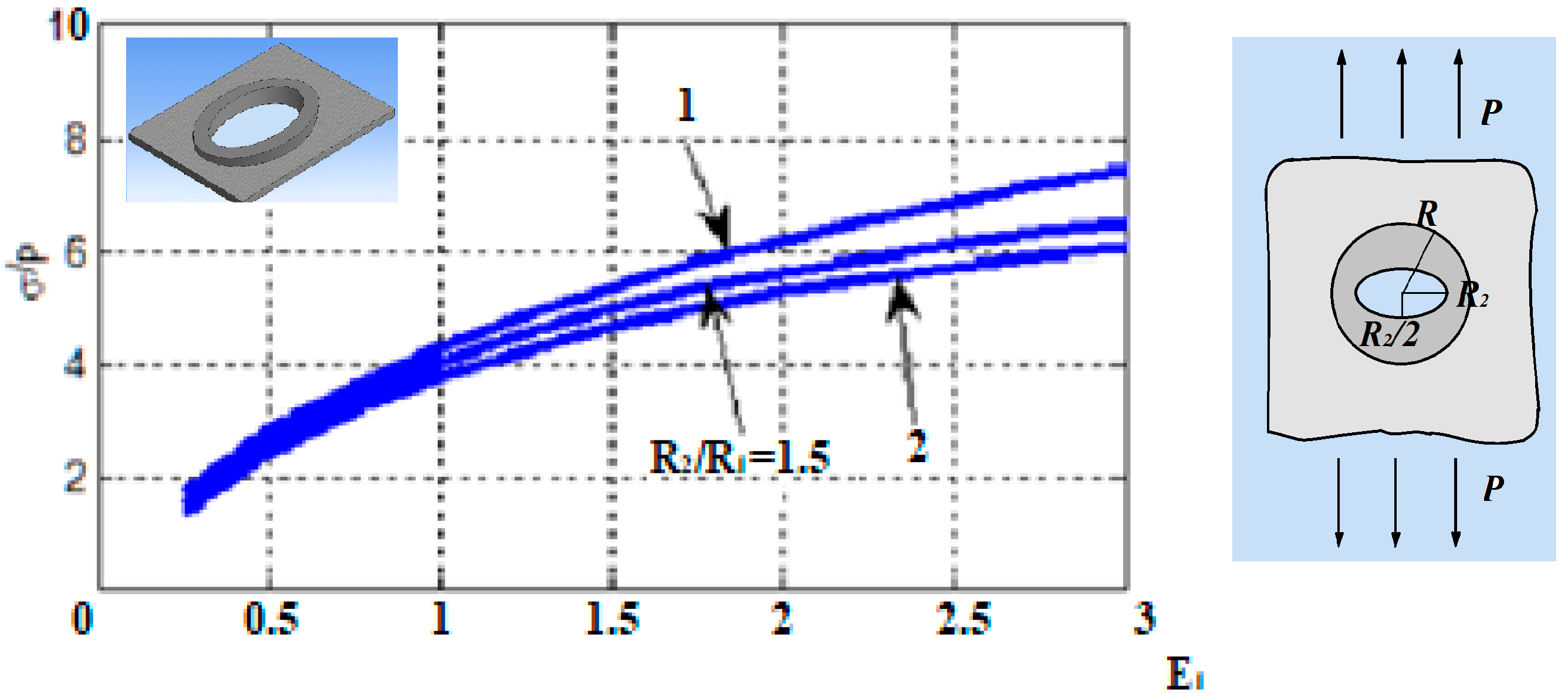
The inclusion of an elliptical shape with semiaxes
is considered. The calculated SCF on the boundary of a circular hole at
and different semiaxis ratios
depending on the value of the modulus of elasticity are shown in
Figure 5.
In
Figure 5, it can be seen that for inclusions that are elongated in the direction of the load, the SCF decreases, but insignificantly.
Homogeneous inclusions of increased thickness. It is assumed that the inclusion and the matrix have different thicknesses
and
, and the load is applied to the matrix. The calculations are performed for the case when the matrix and the inclusion are made of graphite–epoxy, and the inclusion is a ring with an outer radius
R. The calculated SCF for the hole depending on the ratio of the radii
at
is shown in
Figure 6a. Curves 4 and 5 show the maximum hoop stresses in the matrix and the inclusion at their junction, divided by
p at
. Curve 6—normal stresses.
Figure 6b shows similar results for glass–epoxy inclusion. In
Figure 6, it can be seen that increasing the thickness two- to threefold allowed significant reduction in the stress concentration in the hole, and the stresses at the junction of the materials turned out to be insignificant in magnitude. The stress concentration decreased especially for inclusion with lower stiffness (
Figure 6b).
An inclusion from the system of glued orthotropic layers. A coordinate system,
, is introduced, in which these layers occupy the area
and it is assumed that the orthotropy axes are parallel to the coordinate axes
Ox and
Oy, where
A homogeneous orthotropic layer, whose median plane is located at
, is considered. Hooke’s law for the layer is written in the form:
where
is a matrix of elastic constants.
The case where a laminated system in which there are 2
N + 1 layers
is considered. In addition, it is assumed that
. It is assumed that the connected system of layers is deformed such that the normal to the median plane of the zero layer remains straight. Then, the deformations will be the same for all layers, i.e.,
The average stresses in the layer system will be:
where:
.
The interdependencies between average stresses and strains (Hooke’s law) will then be written as:
where:
The average stresses and strains satisfy the equations of the plane problem of the anisotropic theory of elasticity for a plate of thickness
H with elastic constants described by the matrix
B [
25].
The stresses in the
k-th layer due to the obtained average stresses are determined by the formulas:
A graphite–epoxy plate with a hole of radius
a, thickness
is considered. This plate is reinforced by gluing rings on both sides.
, thickness
. In
Figure 7, by line 2 the calculated SCF at
, and the reinforcement is made of the same material. The case where the reinforcement is made of glass–epoxy is also considered. Here, curve S describes the average stresses in the inclusion, curve 0 describes the stresses in the central part of the plate, and curve 1 describes the reinforcements.
A graphite–epoxy plate with elliptical hole with semiaxes
thickness
is considered. The area near the hole with two ring plates with thicknesses
with external radii
is reinforced. The calculations were performed at
and
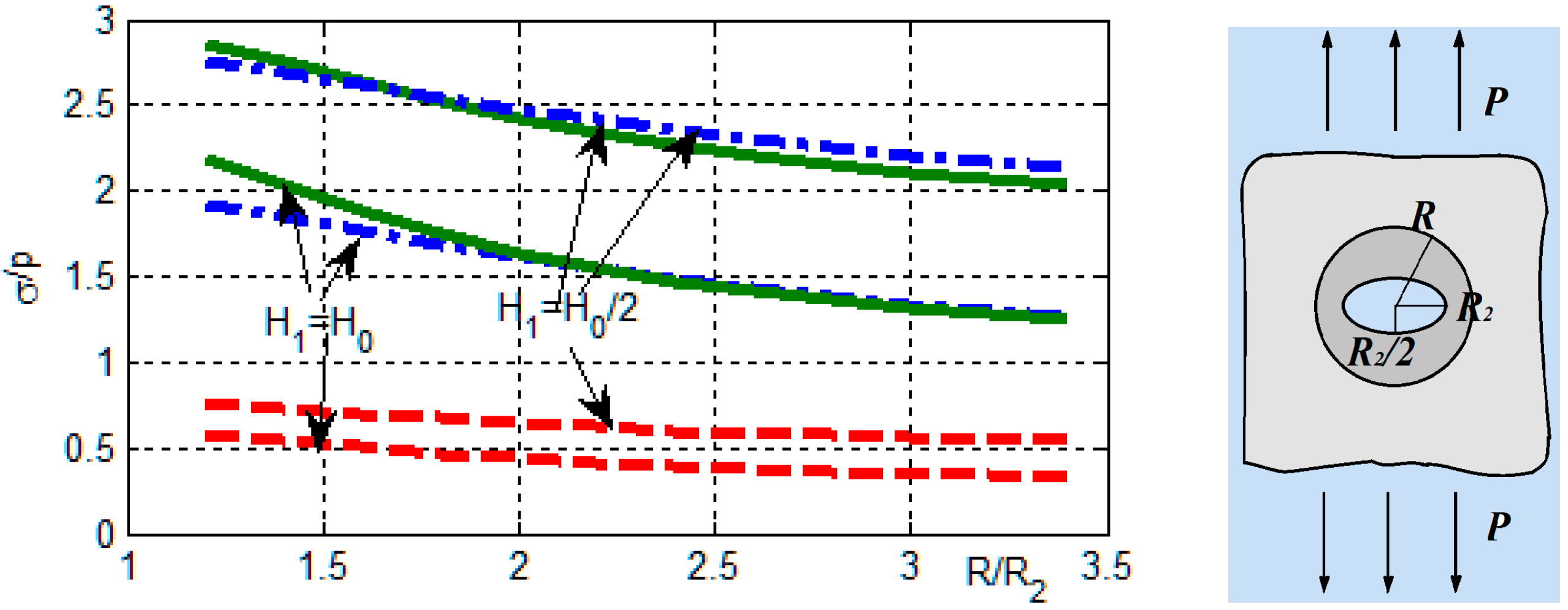
. The solid lines in
Figure 8 show the SCF at the boundary of the hole in the plate at
depending on the size of the overlays
, made of glass–epoxy. Dashed lines show the SCF in the overlays. Dashed dotted lines show the SCF for the case when the plate and overlays are homogeneous—they are made of graphite–epoxy.
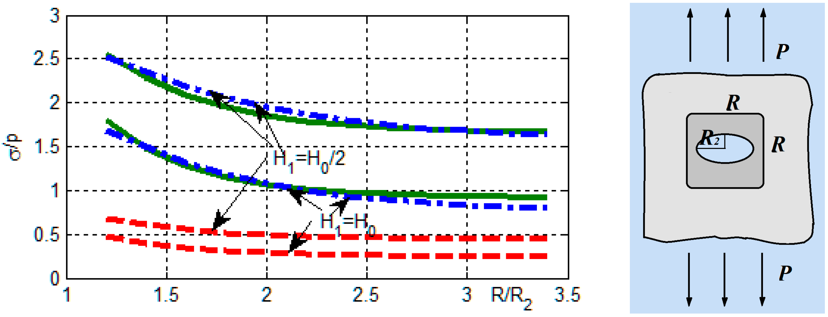
Similar calculation results for the case of overlays of square shapes with half side
R and rounded vertices of circular arcs of radius
R/4 are shown in
Figure 9.
Based on
Figure 7,
Figure 8 and
Figure 9, it follows that increasing the thickness allows significant reduction in the stress concentration near the holes. Stresses are especially reduced near the elliptical holes, elongated in the direction of the loads. Stress concentrations can be further reduced by using quadrature-shaped overlays.
A graphite–epoxy half-plane
y < 0 with a thickness of
with a circular hole of radius a with center in
p is stretched by forces
p in the horizontal direction. The plate is assumed to be reinforced with rings with an outer radius
and thickness
. The calculated SCF at the boundary of the hole with graphite–epoxy reinforcement is shown in
Figure 10 by solid line 1. Line 2 shows the calculated SCF in the plate when the reinforcement is made of glass–epoxy. For comparison, the dashed lines show the SCF for the case of an infinite plane. Here it is assumed everywhere that the stiffness of the materials is maximal in the horizontal direction.
From the data presented, it is clear that near the holes located near the plate boundary, the stress concentration additionally increases.
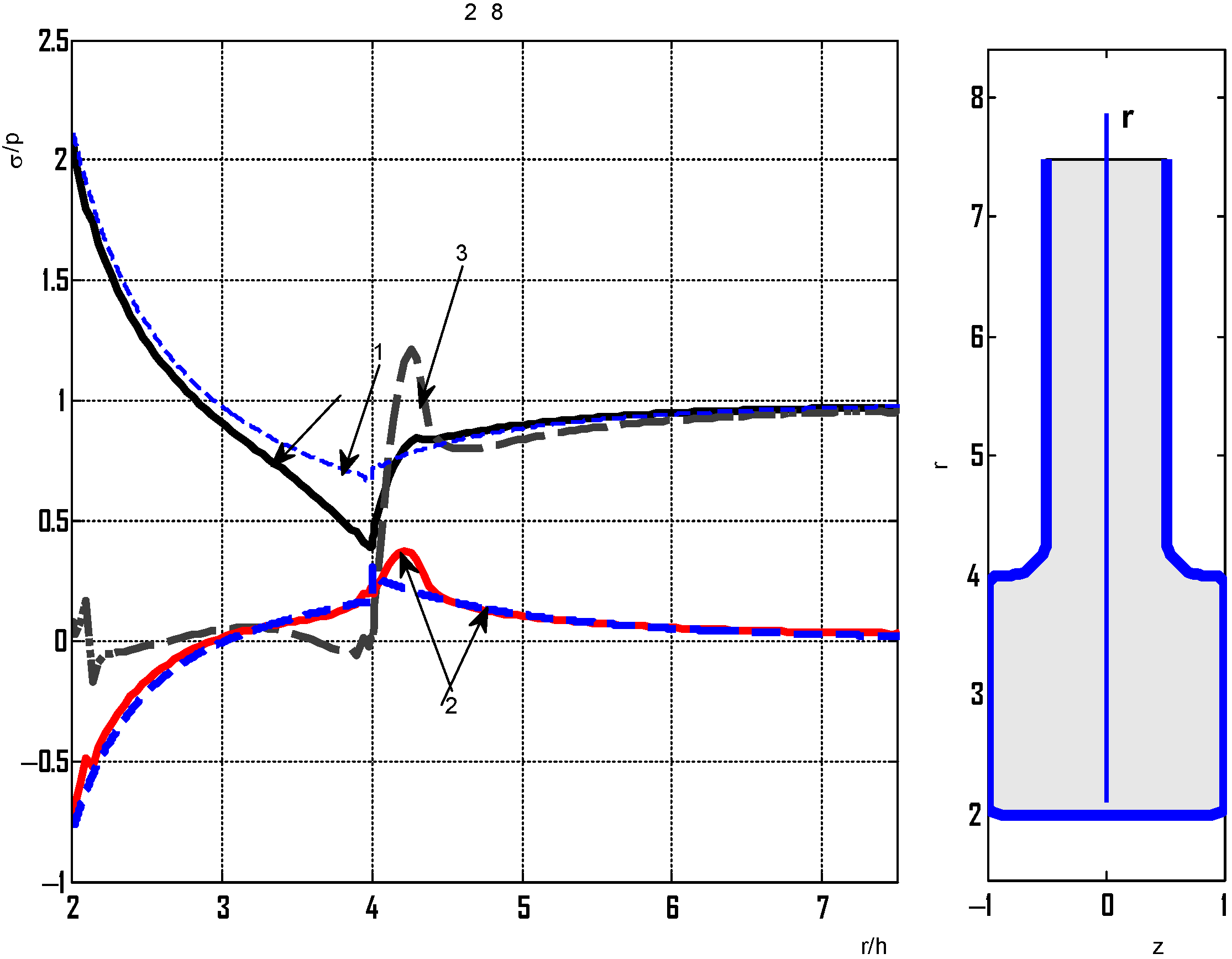
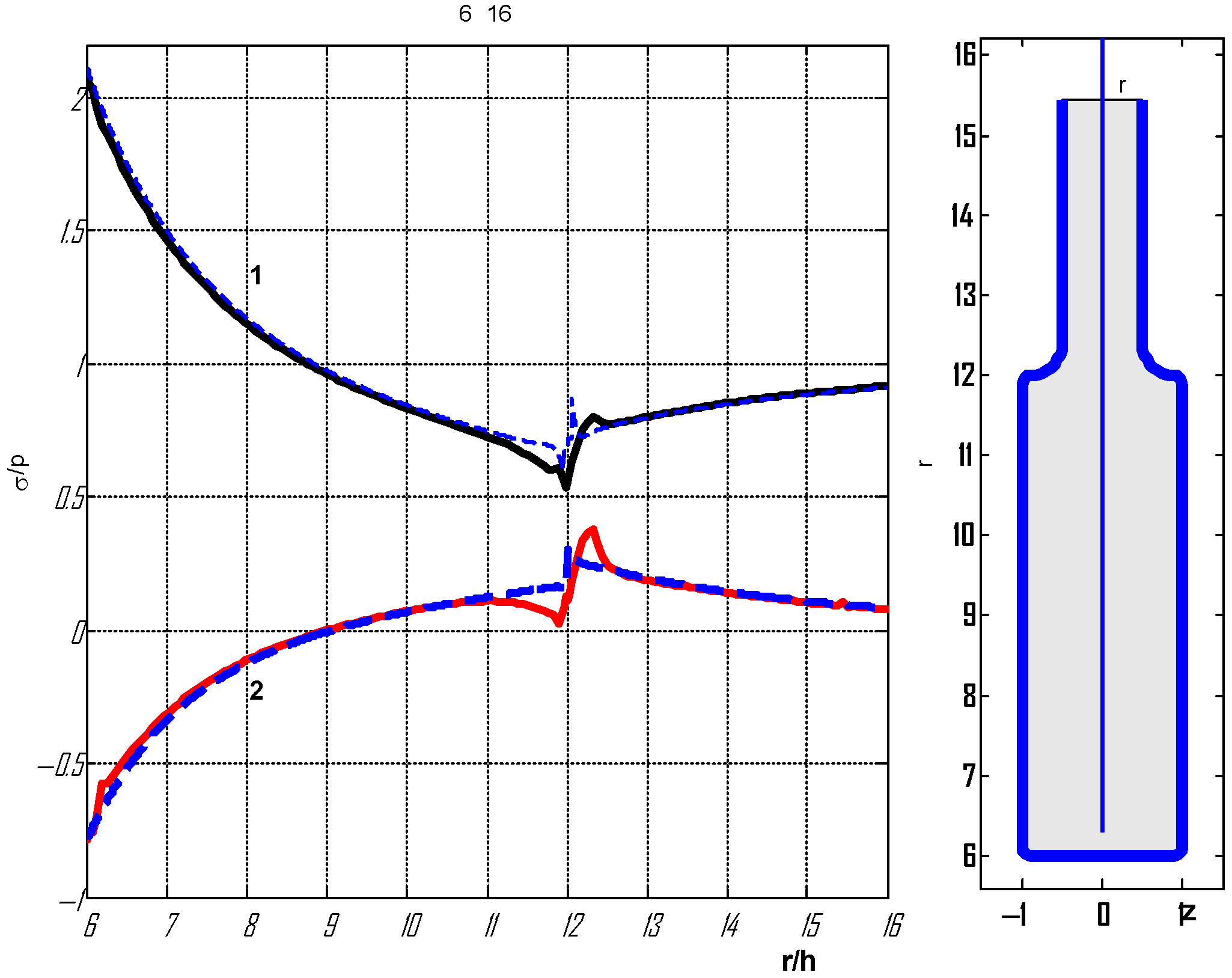
Calculation of stress concentration based on three-dimensional stress theory. A thick plate of variable thickness is considered, referring to a cylindrical coordinate system . It is assumed that the thickness of the plate is 2h at r > b and the reinforced hole is 4h at R < r < b. The material of the plate and reinforcement is isotropic with modulus of elasticity E and Poisson’s ratio . The plate at r > b occupies the area and is under the action of unilateral tension in the direction of the axis Ox by the forces p.
The stresses were initially obtained based on the plane theory elasticity problem (PSS) using the algorithm developed above. The region R < r < b was considered an elastic inclusion of thickness 4h. The obtained stresses are denoted .
To assess accuracy, this problem was solved as a spatial problem using the integral equation method in the form of a Fourier series expansion.
The integral equations for each of the harmonics are given in [
35]. In the calculations, it was assumed that at large distances, the three-dimensional stresses are close in magnitude to the stresses obtained on the surface of the plane problem. In this regard, the plate was considered a limited
and boundary conditions were given for stresses at
r =
c (other boundaries of the plate are not loaded).
First, a small hole was considered with
and
accepted. In addition, all corner points were rounded by arcs of a circle of radius
h/
5 (the shape of the plate cross section is shown in
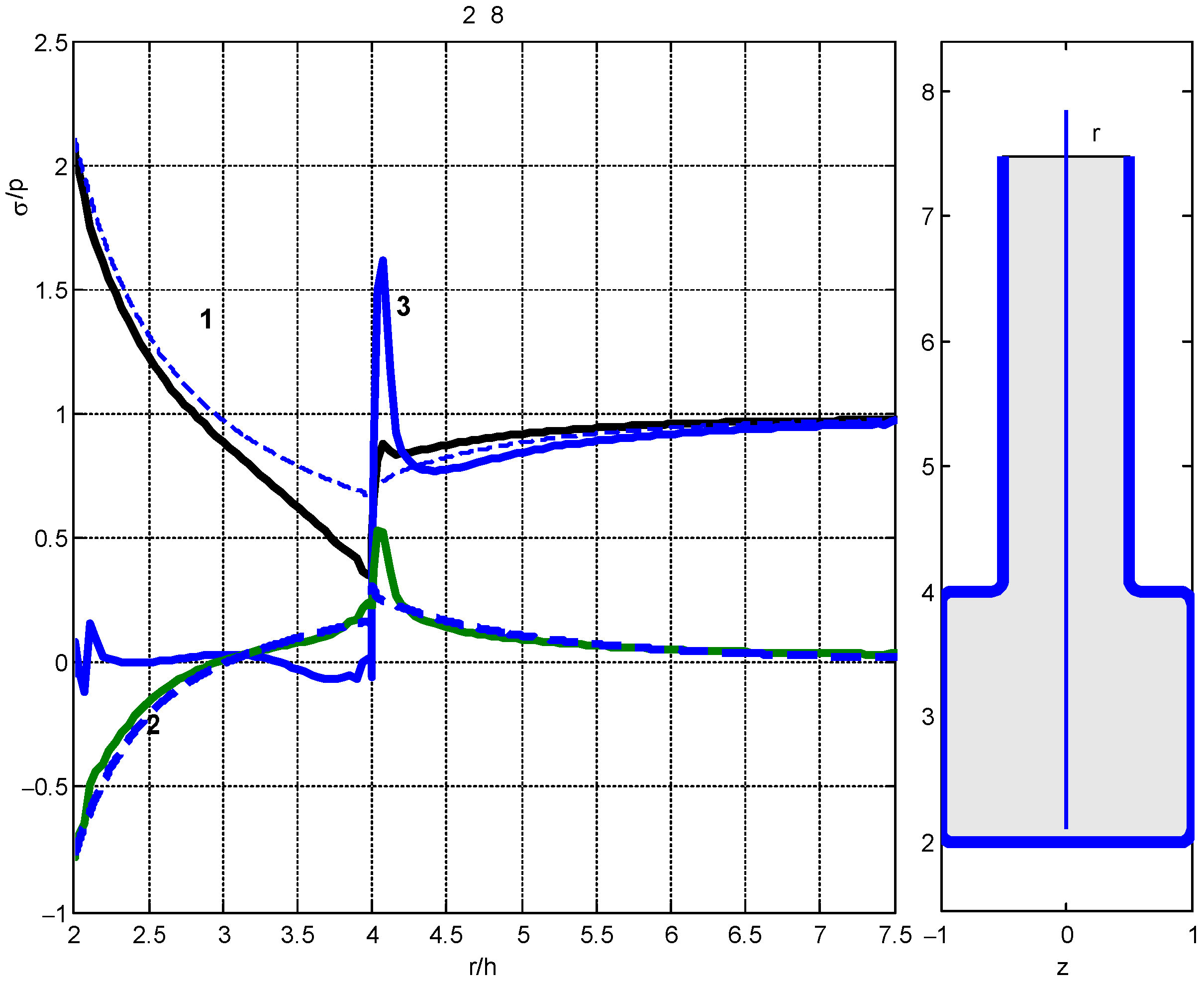
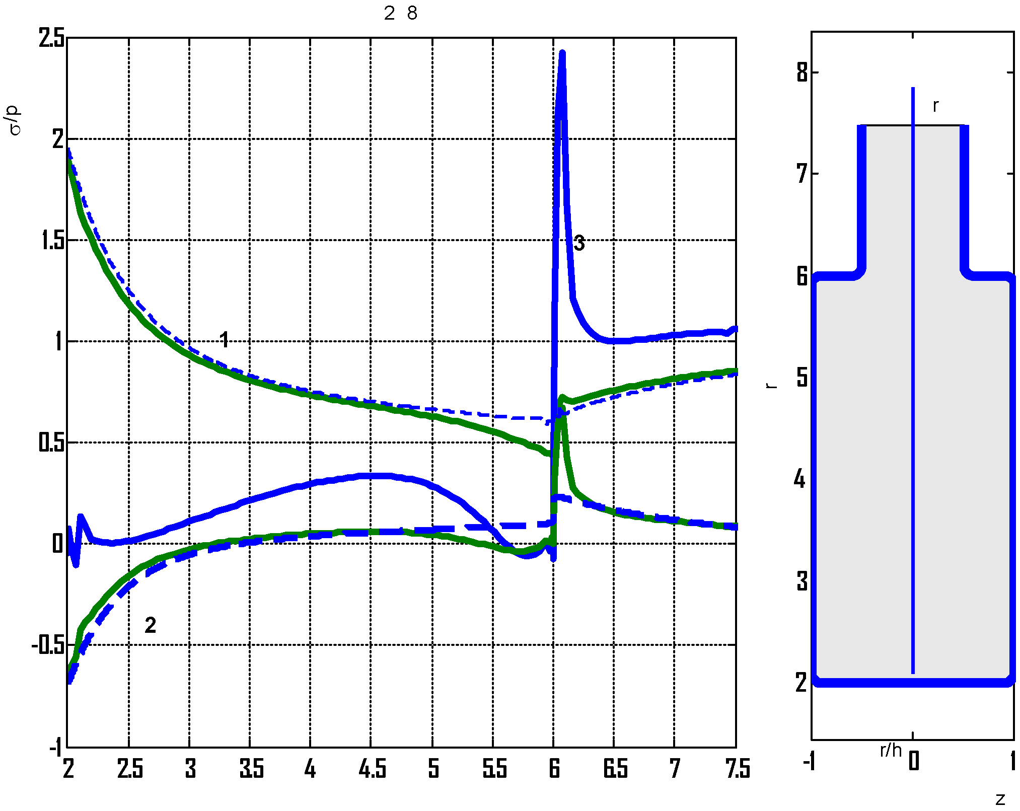
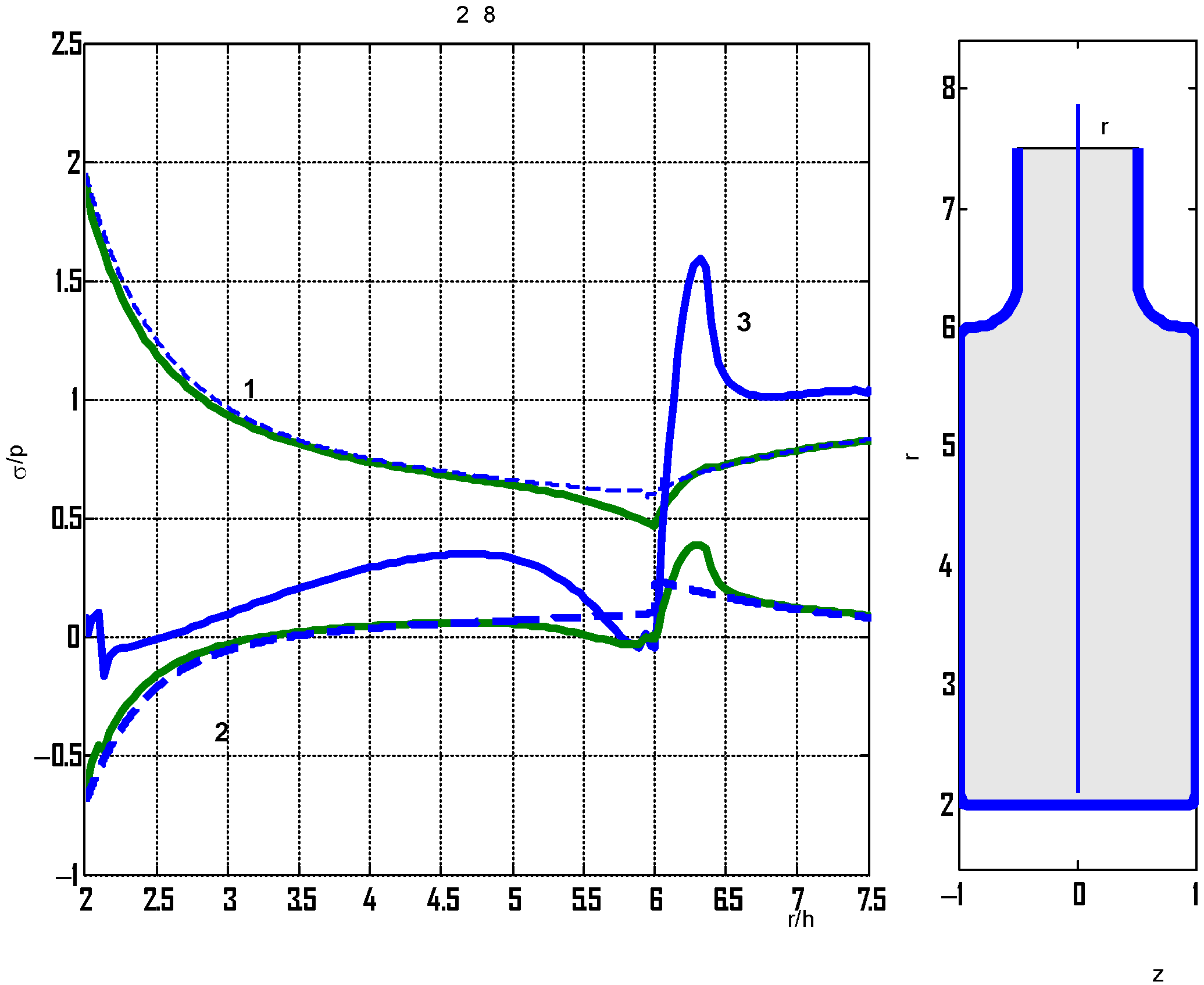
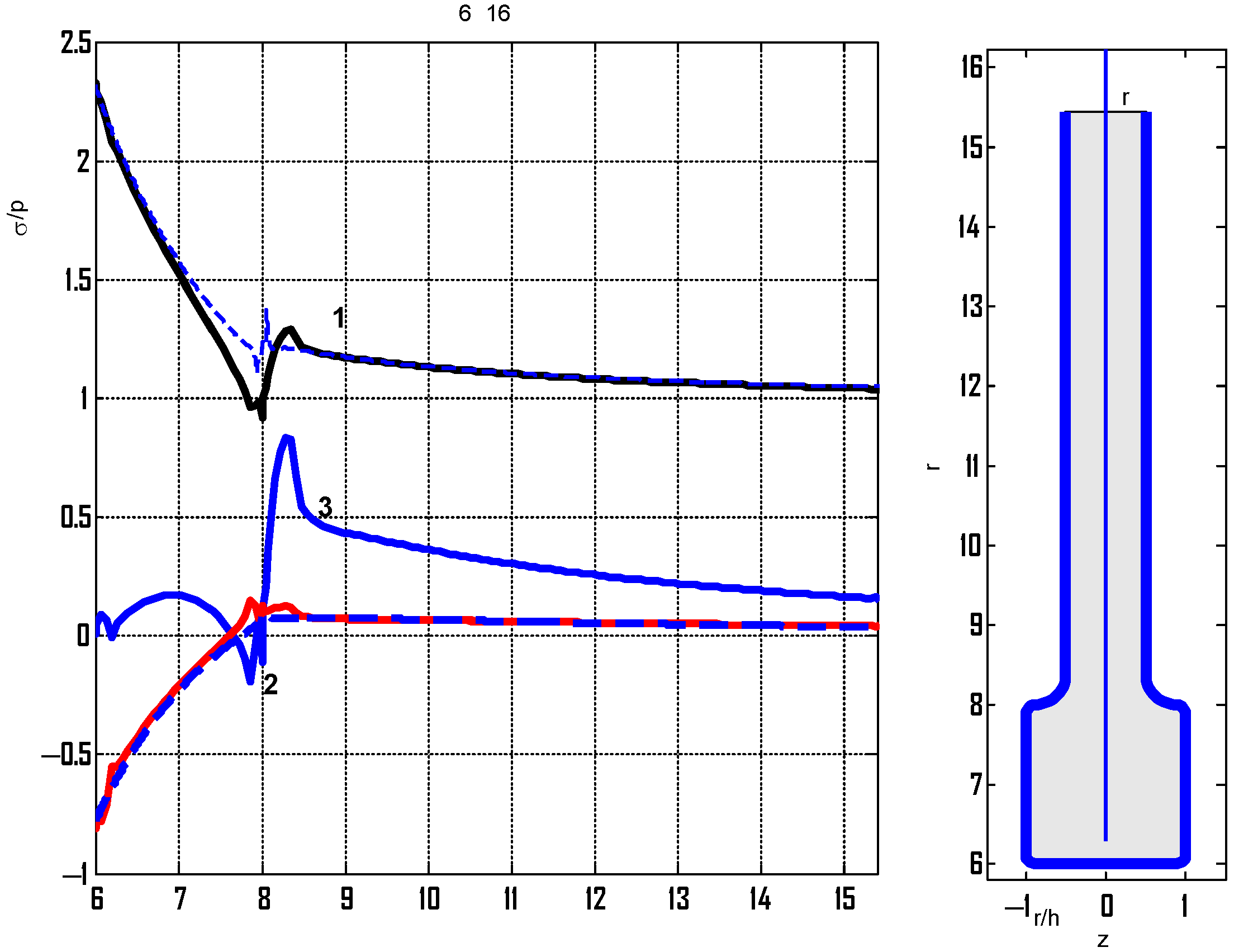
Figure 11 on the right). The calculated stresses at the plate boundary based on the three-dimensional theory are shown by solid lines. Here, curves 1—correspond to relative stresses
at the boundary of the section
x = 0; curve 2—relative stresses
at the boundary of the section
y = 0 (on the curve, which we denote by
); curve 3—relative stresses in the same cross section
, where
is normal stresses (which act on planes perpendicular to the curve
).
The dashed lines correspond to the relative stresses calculated on the basis of the PSS, and curve 1 correspond to the relative stresses in the section x = 0 and curve 2 represents relative stresses in the section y = 0.
It can be seen that the stresses calculated according to different theories at points far distant from the hole turned out to be close in magnitude, which indicates the correct choice of the value of
c. The stresses near the hole also turned out to be close in magnitude. Maximum normal stresses
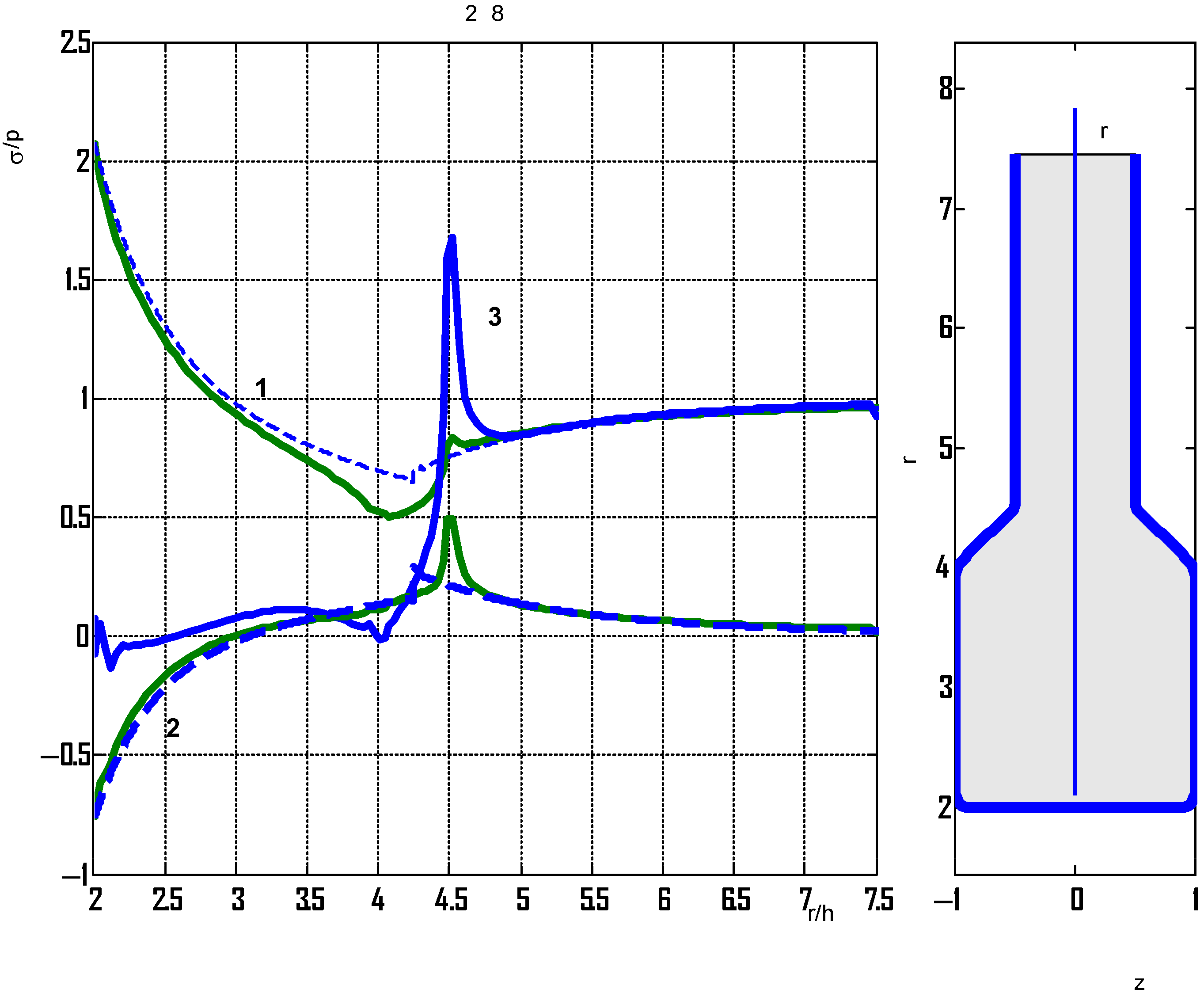
(curve 3) arise in the vicinity of the transition from the plate to the reinforcement. In order to reduce these stresses, a cross section with a linear transition from the plate to the reinforcement was considered at
b = 8.5
h. The calculated relative stresses and the shape of the cross section are shown in
Figure 12.
It can be seen that the stresses obtained by different approaches have somewhat converged, but the normal stresses in the transition zone also turned out to be high.
To reduce these stresses, the corner points in the transition are rounded with arcs of a circle of larger radius 0.8
h (
Figure 13, right).
It can be seen that the axial stresses have significantly decreased and the stresses for the thus-reinforced plate can be determined based on the PSS relations.
A plate with an increased reinforcement width is considered. When
b = 12
h, the radius of curvature is taken as
r =
h/5. The calculated relative stresses are shown in
Figure 14.
For the considered case, the maximum stresses were obtained at the point of transition from the plate to the reinforcement (), and the stress concentration near the hole decreased.
The case where the radius of curvature at the junction of the plate and reinforcement is increased and taken to be 0.8
h is considered. The calculated stresses are shown in
Figure 15.
In
Figure 15, it can be seen that during rounding, the axial stresses decreased, and the PSS ratios allow for almost accurate determination of the stresses in plates of variable thickness.
Consider a plate with an increased hole radius
. Calculated relative stresses at radii of curvatures of 0.8
h,
, and
are shown in
Figure 16 and
Figure 17.
It can be seen that for different widths of the reinforcement region and larger hole radii, the stresses obtained on the basis of the plane problem practically coincide with the exact ones, with the exception of the region at their junction.
4. Conclusions
The problem of enhancing the strength of composite structural elements weakened by holes was considered. Two types of reinforcements commonly used in metal structures were investigated: reinforcing of the hole boundaries with rings and increasing the thickness of the areas adjacent to the holes by gluing composite overlays. In the stress analysis, the reinforced areas were modeled as layered elastic inclusions of another material.
It was established that the concentration of stresses near the holes is significantly reduced when the holes are reinforced with internal rings with less stiffness than the plate. For an isotropic ring with a Young’s modulus of E = 100 GPa in a graphite–epoxy plate, the stress concentration in the plate is reduced by more than three times when the ring width is equal to the hole radius.
The reduction in stress concentration in the graphite–epoxy plate by increasing the thickness near the hole was investigated. For the case where the radius of this region is twice the hole radius, the SCF decreases 1.5-fold when the thickness increases twofold and 1.9-fold when the thickness increases threefold.
The calculations have shown that the SCF is significantly reduced when gluing overlays made from a material with less stiffness than the plate. In the case of glass–epoxy overlays with radii twice as large as the circular hole radius of a graphite–epoxy plate, the SCF on the plate itself is reduced by 2.6-fold, and in the overlay layer the SCF is equal to 1 (i.e., no stress concentration in it). Increasing the size of the overlays decreases the stress concentration.
The reliability of the studies, which were performed on the basis of a plane problem, was confirmed by calculations of stresses in isotropic plates of variable thickness based on the three-dimensional theory of elasticity.
It was found that the stresses given by the two-dimensional and three-dimensional theories were in good agreement with each other if the transition region between the reinforcement and the plate were smoothed. In this case, the stresses themselves in the region of this transition decrease. It follows that the transition area between the overlay and the plate must be rounded.
Implementation of the reinforcement method. The process of reinforcing holes in composite structures should be carried out using technologies used in the composites’ manufacture.
The developed approach to reinforcement is especially relevant in the context of sustainable design of composite structural elements, where the key tasks are to reduce material consumption, increase resistance to damage, and extend the service life.
The methodology presented in the study can be used in the process of repair work when defects are detected near the holes. In this case, it is necessary to take into account the thickness and physical and mechanical properties of the glue used to connect the overlays. In the proposed algorithm in this work, the glue can be directly taken into account as an additional layer in a layered inclusion.

