Article

Tsunami Flow Characteristics on the East Coast of the UAE by One-Dimensional Numerical Analysis and Artificial Neural Networking

1
Department of Civil and Environmental Engineering, The National Water and Energy Center, United Arab Emirates University, Al Ain P.O. Box 15551, United Arab Emirates
2
College of Civil Engineering, Fuzhou University, Fuzhou 350108, China
*
Authors to whom correspondence should be addressed.
Sustainability 2025, 17(15), 7036; https://doi.org/10.3390/su17157036
Submission received: 29 June 2025 / Revised: 24 July 2025 / Accepted: 30 July 2025 / Published: 3 August 2025

Abstract

The coastal developments in the Middle East put low priority on tsunami risk assessment due to the rare occurrence and absence of genuine tsunami track records on the coastline in the past. Tsunami-vulnerable coasts, including the east coast of the UAE, need to prepare for, and pay attention to, the impact of future tsunamis due to increased earthquake activity in the region. This study investigated the tsunami characteristics of the nearshore from hypothetical tsunami conditions by applications of numerical modeling and Artificial Neural Network (ANN) methods. The modeling results showed that the maximum tsunami depth at the shore was highest in Khor Fakkan and Mirbih for the given tsunami boundary conditions, while the tsunami withdrawal was greater on the southern bathymetry compared to that on the northern bathymetry when the tsunami period increased. ANN results confirmed that the still sea depth and seabed slope were more important than the tsunami period when predicting the maximum tsunami depth at the shore.

1. Introduction

In recent decades, exponential development and dense waterfront living have signified rapid coastal urbanization in the Middle East [1,2]. However, a systematic tsunami risk assessment for the Gulf of Oman and Arabian Gulf is typically overlooked in the coastal development planning in the region [3]. The identification of possible tsunami sources, their potential to generate tsunamis, and the predicted flow characteristics of tsunami waves are the prime statistics when analyzing the tsunami vulnerability of coastal cities [4]. Tsunami characteristics such as flow depth, velocity, run-up, and inundation distance can be derived from statistical tools [5] and deterministic approaches [6] using tsunami source parameters. Although the field validation of these results is quite challenging, they provide reasonable guidelines for coastal design appraisals against tsunamis [7]. The Makran Subduction Zone (MSZ), the Kazerun strike-slip, and the Zagros Mountain front are potential tsunami generators in the region [8]. Out of them, the MSZ has the greatest possibility of generating tsunami waves due to its position under the Arabian Sea [9]. Owing to the shallow waters of the Arabian Gulf and the absence of documented tsunami occurrences historically, the probability of tsunamis affecting the inner coasts of the Arabian Gulf is deemed minimal; nonetheless, the Arabian Sea and the Indian Ocean bordering the eastern coast of the Arabian Peninsula represent potential areas for tsunamis that could significantly impact its coastal regions [10].In addition, Suppasri et al. [8] identified five possible surface landslide areas located above 500 m, but close to the sea, which could generate devastating tsunamis in the Arabian Gulf in the event of powerful earthquake activity.
Both the 1948 Makran tsunami and the 2004 Indian Ocean tsunami entered the Arabian Sea [11,12]. However, there is no observed tsunami evidence on the east coast of the UAE. This does not warrant that the east coast of the UAE is free from tsunami impact in the future. Although it is not certain, boulder deposits between Fins and Sur in Oman may be attributed to historic tsunamis. Isolated boulders weighing as much as 40 tons at higher elevations of cliffs cannot be emplaced by low-energy waves [13]. Few studies have been conducted to investigate the tsunami impact on the coasts of the Arabian Sea [5,6,14,15,16,17]. Modeling findings indicate that Salalah city in Oman experiences tsunami waves of 2.5 m, while the less populated Sawqara Bay is affected by 4 m waves, following the onset of significant underwater landslides along the Owen Ridge [14]. Browning and Thomas [5] discussed several possibilities that cause tsunamis in the Arabian Sea, among them are that a large submarine landslide could generate an over 9 m high tsunami at the coast of Oman. A hypothetical Mw 8.8 earthquake from the eastern Makran Subduction Zone caused a peak run-up of 1.16 m and a peak flow depth of 1.37 m at Diba coast, whereas run-up would reach 2.57 m and the flow depth would be 2.34 m if a similar earthquake occurred in the western Makran Subduction Zone [15]. A numerical simulation by Aniel-Quiroga et al. [16] concluded that the least inundation would occur at Wudam and Sawadi, while the highest run-up is possible in the west of Muscat by tsunamis from the Makran Subduction Zone. A Geographical Information System (GIS) analysis done by Hereher [17] stressed that the low-lying Al-Batinah coastal plain of Oman is the area most at risk for tsunami threats due to dense population, infrastructure, and services. Numerical simulation with an earthquake of Mw 9.2 predicted a tsunami that can generate a maximum run-up of 2.55 m, a maximum flow depth of 2.2 m, and a maximum inundation of 253 m on the east coast of the UAE [6]. There has not been any basic or advanced tsunami impact analysis on the east coast of the UAE, except for the study of Hamidatou et al. [6].
In this manuscript, we discuss the spatial variation in tsunami depth and velocity in response to the variation in the bathymetry of the east coast of the UAE for hypothetical tsunamis using numerical modeling. Subsequently, the application of an Artificial Neural Network to predict the maximum tsunami depth at the shore is tested from the modeling results.

2. Methods and Data

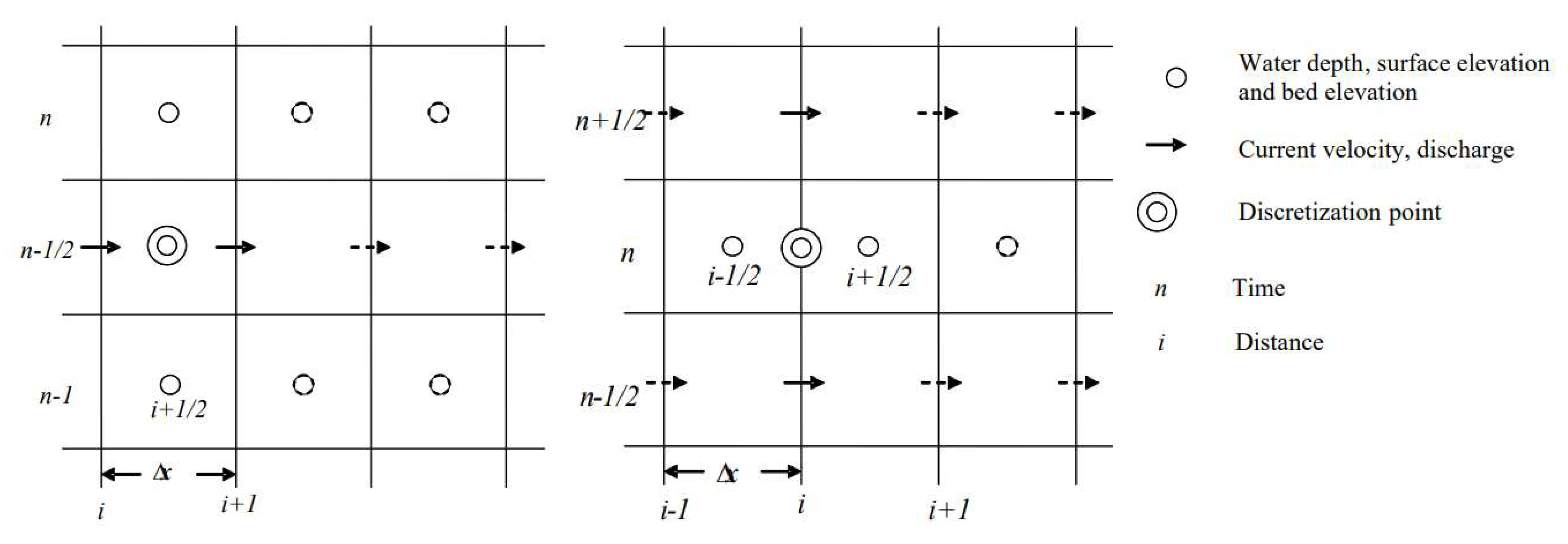
2.1. Numerical Model

A depth-integrated shallow-water wave model was used to simulate tsunami propagation from deep water to shore. The governing equations were based on the conservation of mass and momentum, and they were written in one-dimensional form as follows.
Continuity equation:
ζ t + Q x = 0
Finite difference scheme for the continuity equation:
ζ i + 1 2 n = ζ i + 1 2 n 1 Δ t Δ x Q i + 1 n 1 2 Q i n 1 2
Momentum equation:
Q t + Q 2 h x + g h ζ x + τ ρ = 0
The bottom shear stress can be modeled by
τ = ρ g n 2 h 7 3 Q 2      
where n is the bed roughness coefficient.
Finite difference scheme for the momentum equation:
Q i n + 1 2 Q i n + 1 2 Δ t + 1 Δ x ϑ 1 Q i 1 n 1 2 2 h i 1 n + ϑ 2 Q i n 1 2 2 h i n + ϑ 1 Q i + 1 n 1 2 2 h i + 1 n + g h i n h i + 1 2 n h i 1 2 n Δ x + g n 2 Q i n 1 2 h i n 7 3 Q i n + 1 2 + Q i n 1 2 2 = 0
where ζ is the sea surface elevation, t is the time, x is the distance, Q is the discharge per unit width, h is the sea depth, g is the gravitational acceleration (9.81 m/s2), τ is the bottom shear stress, and ρ is the seawater density (1029 kg/m3). An explicit finite difference numerical scheme was proposed to solve the system of governing equations (Equations (1)–(5)). The staggered method for variables in space and the leapfrog method for variables in time were adopted (Figure 1).
The bed roughness was approximated by Manning’s roughness coefficient, which was 0.025 for the sandy beach and ground surface. The tsunami waves were generated as sinusoidal waves at the offshore boundary, and the wave height and period determined the size of the tsunami at the generation boundary. The numerical model generates the temporal and spatial variation of flow depth and flow velocity at an interval of 2 s. The discretization of distance x = 5 m and the discretization of time is t such that t = x 2 g h , where h is the sea depth at the offshore boundary. The numerical simulation was done until consistent tsunami data were recorded at the shore.

2.2. East Coast of the UAE and Bathymetry

The Arabian Sea is a part of the Indian Ocean and is positioned between the Arabian Peninsula and the Indian subcontinent (Figure 2). It has a total sea surface area of 3,862,000 km2, a maximum width of 2400 km, and a maximum depth of 4652 m [18]. The east coast of the UAE has a length of about 71 km from Dibba Al-Fujairah to Kalba (see the white box in Figure 2), directly facing the Gulf of Oman.
The key geographic formation highlighting the east coast of the UAE is the Hajar Mountains, which spans the total length of the coast. Therefore, rocky cliff coasts are mostly apparent, and, at some places, cliff slopes extend to the sea and form headlands at the shore [19]. In Khor Fakkan and Miribih, where the mountains are situated slightly further inland, pocket urbanization can be seen. In contrast, at the southerly end of the UAE’s east coast, from Fujairah to Khor Kalba, mild slope topography extends a few kilometers inland, where rapid urbanization and commercial development have been in progress [20]. Fujairah Harbor and Oil Terminal are key industrial developments on the east coast, while it is a famous tourism hub due to the culture and history of the coast. The bathymetric slope rapidly increases in the nearshore, so the sea depth often exceeds 50 m within a few kilometers of the coast, dropping to over 1 km depth offshore [20]. Figure 3 shows the bathymetry of the east coast of the UAE as far as 80 km offshore. The sea depth data were interpolated to 5 m grids from 30 m and 90 m grids of satellite imagery, chart data, and GEBCO data. The northern part of the bathymetry has a mild slope as far as about 60 km while maintaining an average sea depth of 100 m, which is followed by a steep bed slope offshore. However, it shows rapidly shallowing water in the nearshore (Figure 3b,c). In contrast, the southern part of the bathymetry has an average slope as far as about 60 km, increasing sea depth up to 300 m, and is followed by an abrupt drop in sea depth to 1 km over a short distance (Figure 3d,e).

2.3. Numerical Model Inputs and Outputs

Sixty-six (66) one-dimensional shore-normal depth profiles were extracted at 1 km intervals covering the bathymetry (Figure 3a). The wave generation boundary was set at 80 km offshore. A tsunami height of 3 m was considered at the generation boundary, referring to the past studies (see Introduction). The period of tsunami waves ranges from 5 min to as long as 60 min [21]. Although spectral analysis of tsunami periods is important for a holistic approach to simulations, due to the unavailability of recorded tsunami data in the Arabian Sea, three distinct tsunamis with periods of 5, 15, and 30 min were considered in this basic study. The text matrix produced 198 cases (three tsunamis x sixty-six profiles). Temporal variations in flow depth and flow velocity were recorded at 20 locations for each profile over 20 km offshore.

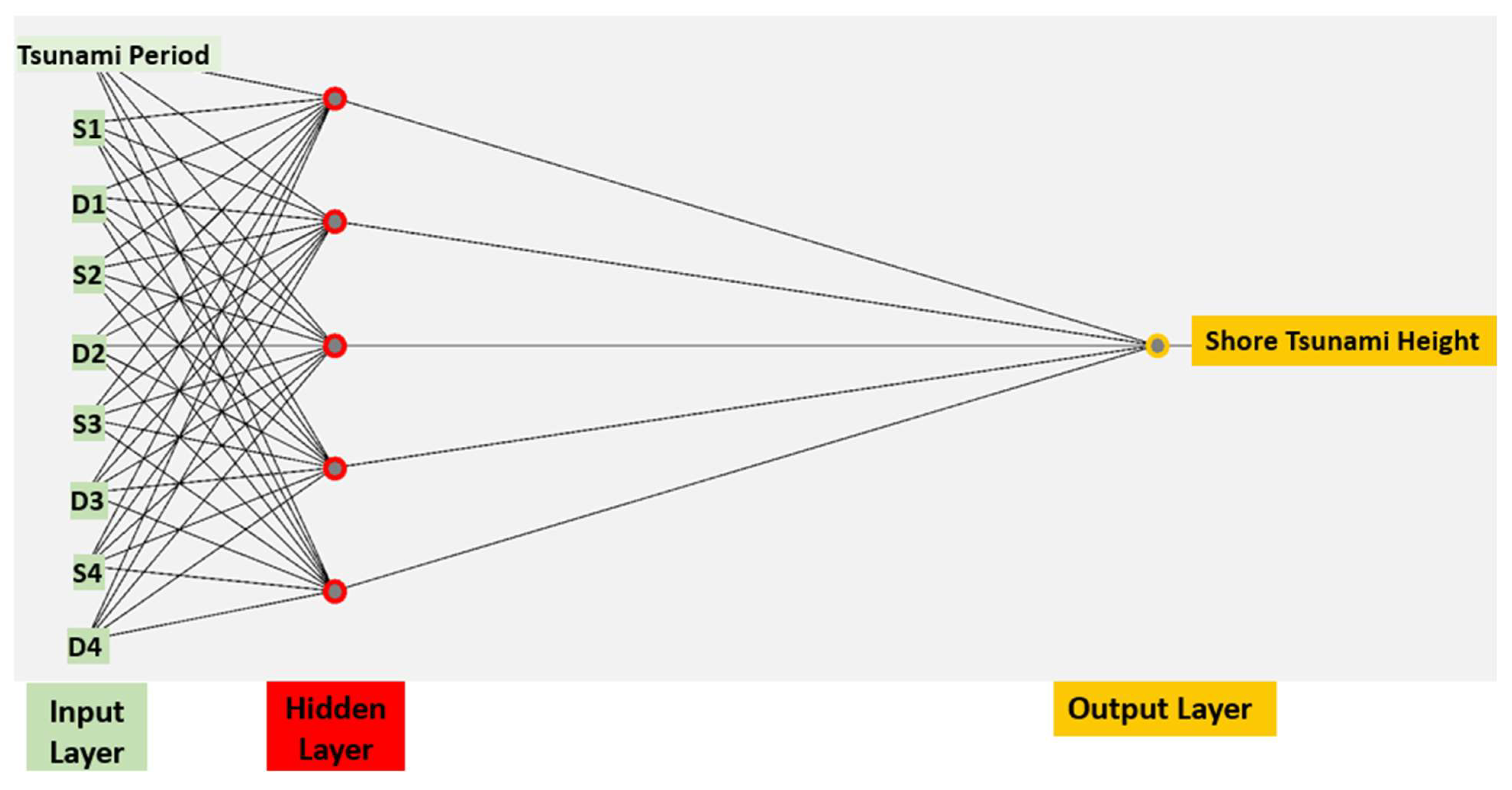
2.4. Artificial Neural Network

Artificial Neural Networks (ANNs) are a subset of artificial intelligence and machine learning that can be utilized as a powerful tool for modeling complex relationships in data. By leveraging numerically modeled tsunami data, ANN models can learn to make predictions of tsunami characteristics at the shore [22]. These models consist of interconnected layers of nodes that process input tsunami data and produce the maximum tsunami depth based on learned weights.

2.4.1. Multilayer Perceptrons

The ANN models built in this study are based on supervised learning of Multilayer Perceptrons (MLPs). These MLPs consist of interconnected layers of units (also called neurons or nodes). The first layer consists of the input nodes, and the last layer consists of the output nodes. Between the input and output layers, there exist one or more hidden layers (usually one, as utilized in this study). The neurons in the layers transfer data from one layer to the following layer in a feedforward way and are interconnected (Figure 4). More details of the architecture of the MLP can be found in [23,24].

2.4.2. Numerical Data Processing for ANN

The characteristics of tsunami waves (wave height and wave period), bathymetry (bed slope and still sea depth), and bed roughness are key parameters to control tsunami propagation and inundation on the ground. In this study, the tsunami period and bathymetry profiles were variables. The nodes in the input layer represent the key parameters of tsunami waves (the independent variables), and the nodes in the output layer represent the dependent variable (the maximum tsunami depth at the shore). The nodes in the hidden layers were determined to minimize error in the prediction. Nine inputs were derived from the tsunami period (one input) and bathymetry (eight inputs). Each one-dimensional bathymetry was divided into four sections and the average bed slope of each section, namely, S1, S2, S3, and S4, was calculated from the wave generation boundary (offshore) to the shore and the corresponding average still sea depth of each section, namely d1, d2, d3, and d4. The statistics of the data set are shown in Table 1.
The magnitude of data varied on different scales. To eliminate the magnitude bias of the input data, they were normalized to values between 0 and 1. The data were divided into a training set and a testing set. The training set was composed of 70% of the data, while the remaining 30% constituted the testing set. Normalization and division of the data into two approximately statistically similar sets with the specified portions were conducted using a filter in WEKA software [25]. The optimum number of nodes in the hidden layer was obtained through a sensitivity investigation that involved training several nets with different numbers of hidden nodes and fixed learning rate and momentum. The learning rate and momentum of the best-performing network were considered the optimum values for this model.

3. Results

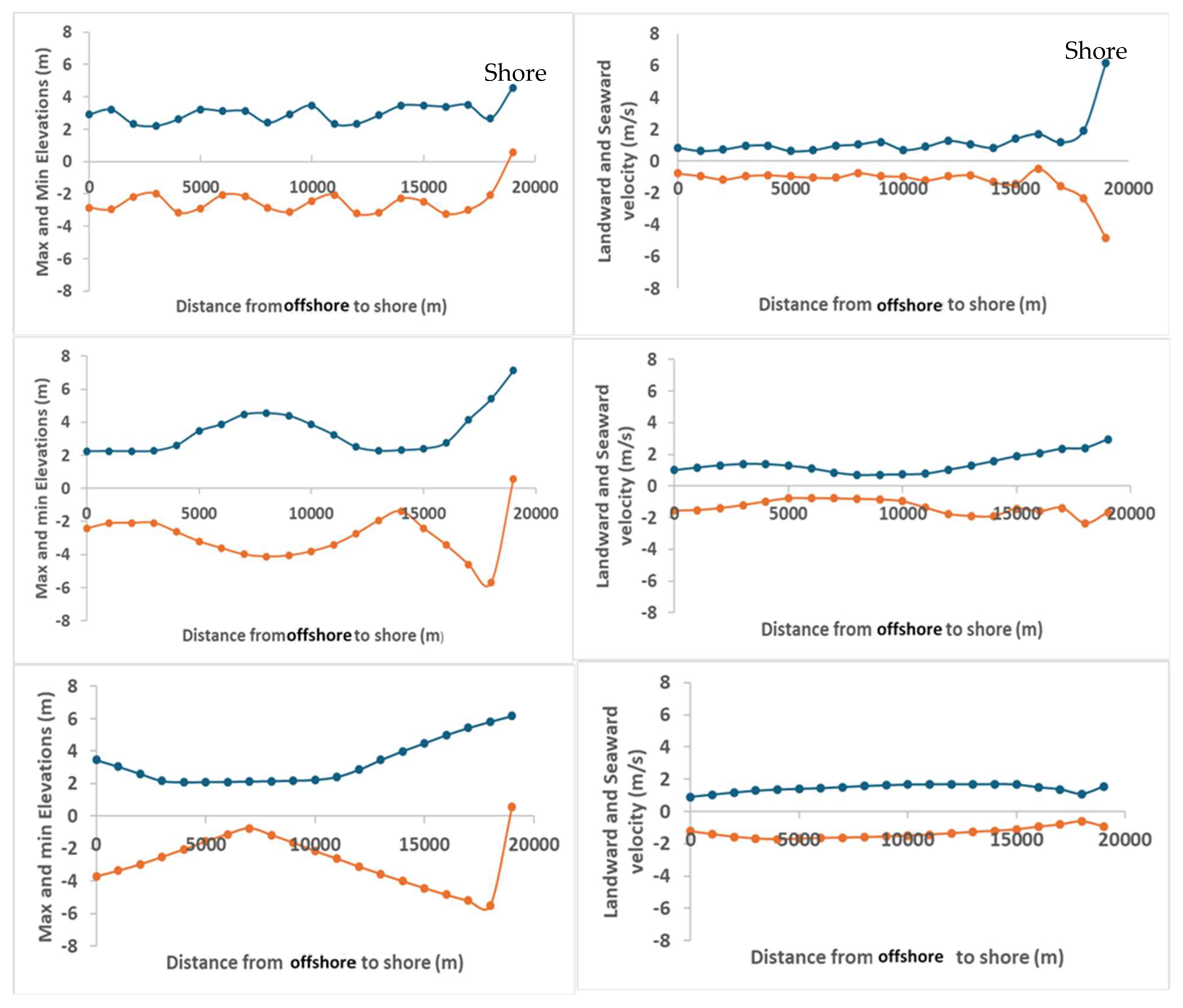
3.1. Numerical Modeling Results
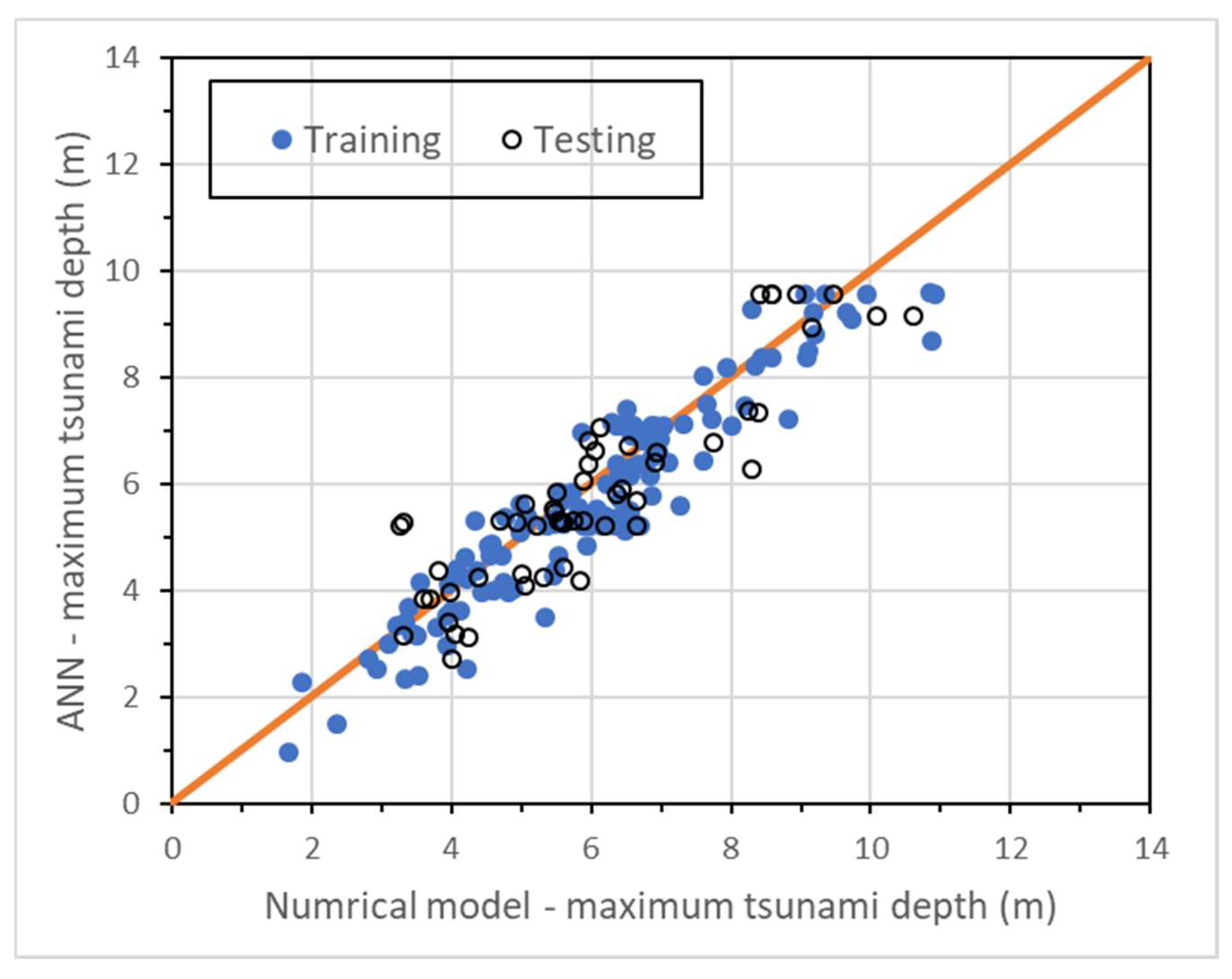
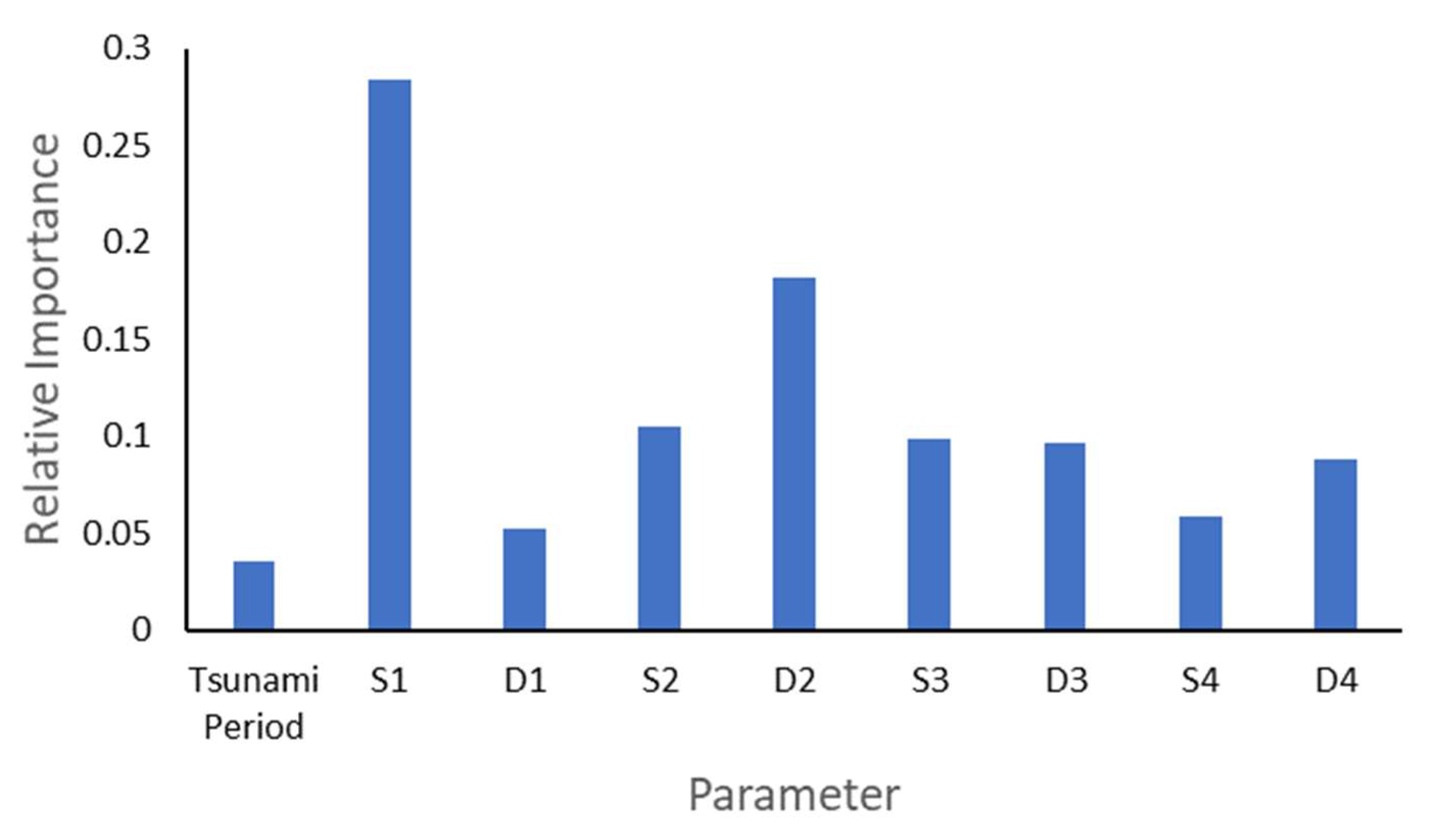
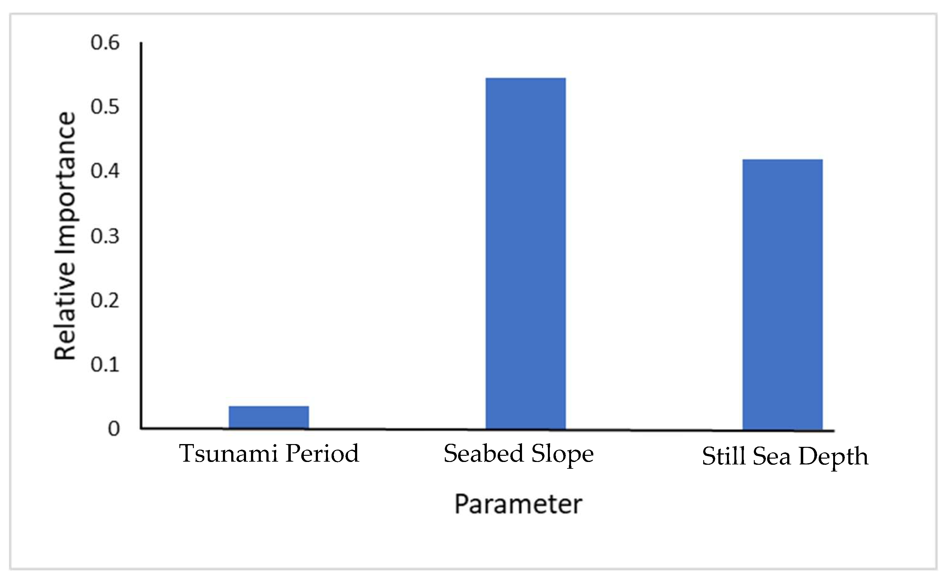
Figure 5 shows the spatial variation of maximum and minimum tsunami elevations and maximum flow velocity in onshore and offshore directions along the profile at 25°28′40″ N 56°18′10″ E (northern bathymetry). The sea depth rapidly increased to 100 m over the first few kilometers from the shore and remained fairly constant over 60 km offshore (Figure 3b). The maximum and minimum tsunami elevations were nearly equal (3 m) until the 5 min tsunami reached the shallow water, but an increment in the elevation was shown near the shore. Similar characteristics were evident for the maximum flow velocity: the maximum flow velocity in the onshore and offshore directions showed a rapid increment near the shore. This indicates that small-period tsunamis could cause greater hydrodynamic disturbances at the shore. When the tsunami period increased (15 and 30 min), a noticeable spatial variation in the maximum and minimum tsunami elevation could be seen. Interestingly, the nodes and anti-nodes of tsunami elevations were present for 15 min and 30 min periods; however, they were not significant for the 5 min tsunami period. Moreover, nodes and anti-nodes were not visible for flow velocities for any tsunami period. When the tsunami period increased from 15 min to 30 min, a phase shift can be seen for the nodes and anti-nodes of the elevations. The shift was due to the increased distance between the nodes and anti-nodes for the 30 min tsunami. The increment in the maximum tsunami elevation for 15 min and 30 min tsunamis was much greater than that for the 5 min tsunami, whereas the maximum tsunami velocity was much smaller at the shore for 15 min and 30 min tsunamis compared to that for the 5 min tsunami. The tsunami withdrawal was shown up to a few kilometers from the shore for 15 min and 30 min tsunamis, but it was not significant for the 5 min tsunami. Figure 6 displays the same results for the profile at 25°01′17″ N 56°21′46″ E (southern bathymetry). The northern and southern bathymetries have differences in bed level changes (Figure 3b–e). The northern bathymetry has a steep slope at the shore, followed by a mile slope over about 60 km, and an average slope offshore (Figure 3b), while the southern bathymetry has an average slope over about 50 km from the shore, followed by a sudden drop in sea depth over a short distance offshore (Figure 3e). The spatial variation of maximum and minimum tsunami elevation for a 5 min tsunami period was similar to that for a 5 min tsunami on the northern bathymetry. However, there was a significant difference in the maximum velocity between the southern and northern bathymetries: The maximum velocity occurred a few kilometers offshore and gradually decreased towards the shore. But, for the northern bathymetry, the maximum velocity increased towards the shore. Although nodes and anti-nodes of elevations were present for 15 min and 30 min tsunamis on the southern bathymetry, they were not as uniform as on the northern boundary. The maximum velocities towards the shore increased for 15 min and 30 min tsunamis on the southern bathymetry; however, it was more or less uniform on the northern bathymetry. A greater tsunami withdrawal was observed for 15 min and 30 min tsunamis on the southern bathymetry compared to that on the northern bathymetry.
Figure 7 shows the spatial variation in the maximum tsunami depth on the east coast of the UAE from the northern boundary to the southern boundary. The maximum tsunami depth varied on the shore. Despite the tsunami period, the maximum tsunami depth was about 4–6 m from 25°35′25″ N to 25°23′20″ N, increased to 8–12 m from 25°20′57″ N to 25°14′27″ N, and decreased to 4–6 m from 25°12′08″ N to 24°59′05″ N. This implied that the middle coastal stretch of the east coast, namely, the Khor Fakkan and Mirbih areas, is highly vulnerable to tsunamis from the Arabian Sea. Both cities have undergone rapid urbanization to date without tsunami protection measures. Hamidatou et al. [6] also highlighted that the coastal developments of Kalba, Al Fujairah, Khor Fakkan, and Dibba need to consider tsunami mitigation planning, public awareness, and education initiatives. Long-period tsunamis generated greater tsunami depths at the shore. The maximum tsunami depth of 15 min and 30 min tsunamis was 1.5 times greater than that of the 5 min tsunami at most locations of the shore. However, opposite results were observed from 25°20′57″ N to 25°19′00″ N, where the highest tsunami depth was due to the 5 min tsunami. It is important to note that the same area received the maximum of the maximum tsunami depths of the entire coast.

3.2. ANN Results

The results of the training and testing of maximum tsunami depth data are shown in Figure 8. As can be seen from the figure, the predicted tsunami depths from both the training data and the testing data agree well for the given input conditions. This shows the success of the trained model for prediction of the maximum tsunami depth at the shore, even when new data that were not used in training were introduced to the network.
In order to understand the relative importance of the input data of ANN, the method of examining the connection weights as suggested by Garson [26] was used. Figure 9 shows the relative importance obtained for the input parameters. The most important feature affecting the maximum tsunami depth at the shore is the average seabed slope near the tsunami generation zone. It is interesting to note that the tsunami period is less important compared to the seabed slope and sea water depth when predicting the maximum tsunami depth at the shore. This indicates that the accuracy of the bathymetry greatly affects the tsunami characteristics at the shore.
In order to have a better assessment of which group of features affects the maximum tsunami depth at the shore, the sum of the relative importance for the slope of the seabed in the four zones and that for the average still sea depth was determined. The relative importance of the three groups—tsunami period, seabed slope, and sea depth—is shown in Figure 10.
It can be seen that the tsunami period has the least effect on the characteristics of the tsunami at the shore. Although both the seabed slope and sea depth have significant effects, it is clear that the slope of the seabed in the direction of tsunami propagation is the major contributor to the behavior of the tsunami at the shoreline. It should be noted that the use of the neural network model developed in this study is restricted to the data in this study. Moreover, despite the small data set used in the study, the results show that artificial neural networking has the potential to accurately predict the nonlinear relationship among the tsunami characteristics at the generation boundary, the bathymetry, and the tsunami characteristics at the shore.

4. Conclusions

The Arabian Sea is not safe from tsunamis. Therefore, countries bordering the Arabian Sea, including the UAE and Oman, need to understand and prepare for such risks, especially when large populations and associated development occupy low-lying coasts. The future risk can be exacerbated due to sea level rise caused by global warming. In this study, numerical modeling was used to simulate the tsunami characteristics on the east coast of the UAE from hypothetically derived tsunami conditions in the deep sea. Then, the modeling results were used to develop an Artificial Neural Network (ANN), and the ANN was applied to predict the maximum tsunami depth at the shore. The results are summarized below.
The maximum and minimum tsunami elevation, and maximum tsunami velocity in onshore and offshore directions, varied from northern to southern bathymetries. For a 5 min tsunami, the maximum and minimum tsunami elevations nearshore were similar; however, the maximum tsunami flow velocity increased towards the shore on the northern bathymetry and decreased towards the shore on the southern bathymetry.
Nodes and anti-nodes of the tsunami elevation were shown for both 15 min and 30 min tsunamis. They were well-organized on northern bathymetry compared to that on southern bathymetry. A clear phase shift of nodes was observed when the tsunami period increased from 15 min to 30 min.
Tsunami withdrawal was significantly smaller for the 5 min tsunami compared to 15 min and 30 min tsunamis. A greater tsunami withdrawal was observed for 15 min and 30 min tsunamis on the southern bathymetry compared to that on the northern bathymetry.
The maximum tsunami depth at the shore was highest in the middle section of the east coast of the UAE for the given tsunami boundary conditions. This indicates that Khor Fakkan and Mirbih could receive a greater tsunami impact compared to the other areas of the east coast of the UAE during tsunami inundations.
The ANN predicted well the maximum tsunami depth at the shore for the given input conditions on the tsunami characteristics and bathymetry. Relative importance analysis confirmed that the characteristics of the bathymetry were more important than those of the tsunami when predicting the maximum tsunami depth at the shore. While the maximum tsunami depth at the shore had a higher sensitivity to the seabed slope than the still sea depth, the significance of the average seabed slope at the tsunami generation boundary was the highest among the other parameters.
Advanced numerical modeling (2D or 3D) with reliable tsunami source information and accurate bathymetric data of the Arabian Sea will be essential for the prediction of the tsunami characteristics at the shore with high accuracy. Although the ANN worked well in this study, the amount of data for training and testing was limited. Future research on neural network models based on larger data sets covering the various possible tsunami events is encouraged. Such neural network models can be integrated into tsunami prediction systems that aid coastal safety and timely warning.

Author Contributions

Conceptualization, N.A.K.N.; Formal analysis, M.A. (Maryam Alshehhi), N.A. (Noura Alahbabi), F.A., M.A. (Maha Ali) and N.A. (Noura Alblooshi); Investigation, A.H.; Writing—original draft, N.A.K.N. and A.H.; Writing—review & editing, C.C. All authors have read and agreed to the published version of the manuscript.

Funding

This study was funded by the UAEU SURE+ grant (G00004709).

Institutional Review Board Statement

Not applicable.

Informed Consent Statement

Not applicable.

Data Availability Statement

The original contributions presented in this study are included in the article. Further inquiries can be directed to the corresponding author.

Conflicts of Interest

The authors declare no conflict of interest.

References

  1. Aldogom, D.; Albesher, S.; Al Mansoori, S.; Nazzal, T. Assessing Coastal Land Dynamics Along UAE Shoreline Using GIS and Remote Sensing Techniques. IOP Conf. Ser. Earth Environ. Sci. 2020, 540, 012031. [Google Scholar] [CrossRef]
  2. Luijendijk, A.P.; Vasiliki, E.; Morelissen, D.R.; Hoteit, I.; Ranasinghe, R. Regime Shifts in Future Shoreline Dynamics of Saudi Arabia. Front. Mar. Sci. 2022, 8, 1–12. [Google Scholar] [CrossRef]
  3. UN.ESCAP. Tsunami Early Warning Systems in the Countries of the North West Indian Ocean Region with Focus on India, Islamic Republic of Iran, Pakistan, and Oman: Synthesis Report; UNESCAP: Bangkok, Thailand, 2017. [Google Scholar]
  4. Jelínek, R.; Krausmann, E. Approaches to tsunami risk assessment. EUR Sci. Tech. Res. Ser. 2008, 1018–5593. Available online: https://publications.jrc.ec.europa.eu/repository/handle/JRC48713 (accessed on 29 July 2025).
  5. Browning, J.; Thomas, N. An assessment of the tsunami risk in Muscat and Salalah, Oman, based on estimations of probable maximum loss. Int. J. Disaster Risk Reduct. 2016, 16, 75–87. [Google Scholar] [CrossRef]
  6. Hamidatou, M.; Almandous, A.; Alebri, K.; Alameri, B.; Megahed, A. Deterministic Tsunami Hazard Assessment for the Eastern Coast of the United Arab Emirates: Insights from the Makran Subduction Zone. Sustainability 2024, 16, 10665. [Google Scholar] [CrossRef]
  7. Fukui, N.; Mori, N.; Miyashita, T.; Shimura, T.; Goda, K. Subgrid-scale modeling of tsunami inundation in coastal urban areas. Coast. Eng. 2022, 177, 104175. [Google Scholar] [CrossRef]
  8. Suppasri, S.; Latcharote, P.; Pokavanich, T.; Al-Salem, K. Tsunami Hazard Assessment for the Arabian Gulf from Earthquakes and Surface Landslides. J. Jpn. Soc. Civ. Eng. Ser B2 (Coast. Eng.) 2016, 72, I_1675–I_1680. [Google Scholar] [CrossRef] [PubMed]
  9. Byrne, D.E.; Sykes, L.R.; Davis, D.M. Great thrust earthquakes and aseismic slip along the plate boundary of the Makran subduction zone. J. Geophys. Res. 1992, 97, 449–478. [Google Scholar] [CrossRef]
  10. Jordan, B.R. Tsunamis of the Arabian Peninsula a Guide of Historic Events. Sci. Tsunami Hazards 2008, 27, 31. [Google Scholar]
  11. Okal, E.A.; Fritz, H.M.; Raad, P.E.; Synolakis, C.; Al-Shijbi, Y.; Al-Saifi, M. Oman field survey after the December 2004 Indian Ocean Tsunami. Earthq. Spectra 2006, 22, S203–S218. [Google Scholar] [CrossRef]
  12. Pararas-Carayannis, G. The Potential of tsunami generation along the Makran subduction zone in the Northern Arabian Sea. Sci. Tsunami Hazards 2006, 24, 358. [Google Scholar]
  13. Hoffmann, G.; Reicherter, K.; Wiatr, T.; Grutzner, C.; Rausch, T. Block and boulder accumulations along the coastline between Fins and Sur (Sultanate of Oman): Tsunamigenic remains? Nat. Hazards 2013, 65, 851–873. [Google Scholar] [CrossRef]
  14. Rodriguez, M.; Chamot-Rooke, N.; Hébert, H.; Fournier, M.; Huchon, P. Owen Ridge deep-water submarine landslides: Implications for tsunami hazard along the Oman coast. Nat. Hazards Earth Syst. Sci. 2013, 13, 417–424. [Google Scholar] [CrossRef]
  15. El-Hussain, I.; Omira, R.; Al-Bulushi, K.; Deif, A.; Al-Habsi, Z.; Al-Rawas, G.; Mohamad, A.; Al-Jabri, K.; Baptista, M.A. Tsunami hazard assessment along Diba-Oman and Diba-Al-Emirates coasts. MATEC Web Conf. 2017, 120, 06007. [Google Scholar] [CrossRef]
  16. Aniel-Quiroga, Í.; Álvarez-Gómez, J.A.; González, M.; Martínez Sánchez, J.; Parro, L.M.; Aguirre-Ayerbe, I.; Fernández, F.; Medina, R.; Al-Yahyai, S. Tsunami Hazard assessment and Scenarios Database for the Tsunami Warning System for the coast of Oman. Nat. Hazards Earth Syst. Sci. Discuss. 2018, 1–30. [Google Scholar] [CrossRef]
  17. Hereher, M.E. Assessment of Infrastructure Vulnerability to Tsunamis upon the Coastal Zone of Oman Using GIS. Geosciences 2020, 10, 175. [Google Scholar] [CrossRef]
  18. Kohi, M.; Babaeian, I. Projections of the Sea Level Rise and Sea Surface Temperature of Pars Sea Region Under SSPs Scenarios. Nivar 2022, 46, 179–189. [Google Scholar]
  19. Feulner, G.R. Geography and Geology of the United Arab Emirates: A Naturalist’s Introduction. In A Natural History of the Emirates; Burt, J.A., Ed.; Springer: Cham, Switzerland, 2024. [Google Scholar]
  20. Burt, J.A.; Paparella, F. The Marine Environment of the Emirates. In A Natural History of the Emirates; Burt, J.A., Ed.; Springer: Cham, Switzerland, 2024. [Google Scholar]
  21. IOC. Tsunami Glossary, 2019. IOC/2008/TS/85 rev. 4, 4th ed.; Intergovernmental Oceanographic Commission (IOC): Paris, France, 2019. [Google Scholar]
  22. Wang, Y.; Imai, K.; Miyashita, T.; Miyashita, T.; Ariyoshi, K.; Takahashi, N.; Satake, K. Coastal tsunami prediction in Tohoku region, Japan, based on S-net observations using artificial neural network. Earth Planets Space 2023, 75, 154. [Google Scholar] [CrossRef]
  23. Fausett, L. Fundamentals of Neural Network; Prentice Hall: Hoboken, NJ, USA, 1994. [Google Scholar]
  24. Goodfellow, I.; Bengio, Y.; Courville, A. Deep Learning; MIT Press: Cambridge, MA, USA, 2016. [Google Scholar]
  25. WEKA: A Machine Learning Software in Java, Version 3.8.6; The University of Waikato: Hamilton, New Zealand, 2025.
  26. Garson, G.D. Interpreting neural network connection weights. Artif. Intell. Expert 1991, 6, 47–51. [Google Scholar]
Figure 1. Staggered and leapfrog scheme for numerical simulation. Left: Continuity equation, Right: Momentum equation.
Sustainability 17 07036 g001
Figure 2. Arabian Sea and the east coast of the UAE. Credit: wikipedia.org and Google Earth.
Sustainability 17 07036 g002
Figure 3. (a) Two-dimensional bathymetry of the east coast of the UAE extending about 80 km from the shore, (be) shore normal one-dimensional bathymetry [1, 2, 3, and 4 in Figure 3a] at 25°28′40″ N 56°18′10″ E, 25°20′57″ N 56°21′22″ E, 25°12′08″ N 56°19′45″ E, and 25°01′17″ N 56°21′46″ E, respectively.
Sustainability 17 07036 g003
Figure 4. Multilayer perceptron architecture for tsunami prediction.
Sustainability 17 07036 g004
Figure 5. Spatial variation of maximum and minimum tsunami elevation (left) and maximum flow velocity in onshore and offshore directions (right) for the profile of 25°28′40″ N 56°18′10″ E (Figure 3b). First row graphs for the tsunami period of 5 min, second row for 15 min, and third row for 30 min. Tsunami elevation was measured relative to mean sea level (0 m). Negative numbers indicate the maximum velocity in the offshore direction.
Sustainability 17 07036 g005
Figure 6. Spatial variation of maximum and minimum tsunami elevation (left) and maximum flow velocity in onshore and offshore directions (right) for the profile of 25°01′17″ N 56°21′46″ E (Figure 3e). First row graphs for the tsunami period of 5 min, second row for 15 min, and third row for 30 min. Tsunami elevation was measured relative to mean sea level (0 m). Negative numbers indicate the maximum velocity in the offshore direction.
Sustainability 17 07036 g006
Figure 7. Spatial variation in maximum tsunami depth at shore for tsunami periods of 5, 15, and 30 min. The incident tsunami height at the generation boundary was 3 m (~80 km offshore).
Sustainability 17 07036 g007
Figure 8. Comparison between ANN-predicted and numerical model-predicted maximum tsunami depth at the shore for the training data and testing data.
Sustainability 17 07036 g008
Figure 9. Relative importance of tsunami period, average sea depth, and average slope to the prediction of maximum tsunami depth at the shore.
Sustainability 17 07036 g009
Figure 10. Relative importance of tsunami period, seabed slope, and still sea depth to the maximum tsunami depth at the shore.
Sustainability 17 07036 g010
Table 1. Statistics of the analyzed data.
Model Variable.Range of Values MeanStandard Deviation
Tsunami Period (min)5–3016.506810.3644
S10.0043–0.02410.01010.0053
D1 (m)160–504279.369995.0859
S20.0009–0.00820.00340.0025
D2 (m)114–206136.589027.5242
S3−0.0005–0.00090.00040.0004
D3 (m)96–125100.63016.7444
S4 0.0024–0.00690.00360.0011
D463–7670.73973.8225
Maximum tsunami depth at shore (m)1.8585–12.85095.69532.0520
Disclaimer/Publisher’s Note: The statements, opinions and data contained in all publications are solely those of the individual author(s) and contributor(s) and not of MDPI and/or the editor(s). MDPI and/or the editor(s) disclaim responsibility for any injury to people or property resulting from any ideas, methods, instructions or products referred to in the content.

