Article

Converter-Based Power Line Emulators for Testing Grid-Forming Converters Under Various Grid Strength Conditions

Smart Grid Research Division, The Korea Electrotechnology Research Institute, 27 Dosi-Cheomdan Saneop-ro, Nam-gu, Gwangju-si 61751, Republic of Korea
*
Author to whom correspondence should be addressed.
Sustainability 2025, 17(15), 6690; https://doi.org/10.3390/su17156690
Submission received: 5 April 2025 / Revised: 20 June 2025 / Accepted: 14 July 2025 / Published: 22 July 2025

Abstract

Grid-forming (GFM) converters have been critical in DER-dominant power systems, ensuring stability, but their performance is highly sensitive to grid conditions such as system strength. Testing GFM converters under a wide range of grid strengths (from strong high-inertia systems to very weak grids) and fault scenarios is challenging, as traditional test facilities and static grid simulators have limitations. To address this problem, this paper proposes a converter-based power line emulator that provides a flexible, programmable grid environment for GFM converter testing. The emulator uses power electronic converters to mimic transmission line characteristics, allowing for the adjustment of effective grid strength (e.g., short-circuit ratio changes). The proposed approach is validated through detailed PSCAD simulations, demonstrating its ability to provide scalable weak-grid emulation and comprehensive validation of GFM converter control strategies and stability under various grid conditions. This research highlights that the converter-based emulator offers enhanced flexibility and cost-effectiveness over traditional testing setups, making it an effective tool for GFM converter performance test.

1. Introduction

The integration of inverter-based resources (IBRs), such as photovoltaic (PV), wind, and energy storage systems (ESSs), into reshaping power systems is leading to a significant depletion of conventional synchronous inertia and short-circuit strength, and this weak power grid condition may pose substantial challenges to maintaining stable voltage, frequency, and synchronization, as the penetration of distributed energy resources (DERs) intensifies [1,2,3,4,5,6,7,8,9,10,11,12,13,14,15,16,17,18,19,20]. Grid-forming (GFM) converters have emerged as a promising solution to mitigate these challenges and ensure the stability of DER-dominated power systems [1,21,22,23]. Unlike traditional grid-following (GFL) converters, which rely on a phase-locked loop (PLL) to synchronize with an existing grid voltage, GFM converters can establish their own reference voltage and frequency, effectively emulating the behavior of virtual synchronous generators. By operating as controllable voltage sources, GFM converters inherently provide grid support, such as damping frequency deviations and regulating voltage, thereby enhancing the stability of weak grids that are interconnected or isolated. This capability makes GFM converters an attractive solution for weakening power systems with high renewable penetration, where GFL inverters often struggle with synchronization stability, transient response, and weak grid operation. However, the widespread deployment of GFM converters introduces several complexities. Ensuring stable operation in large-scale systems requires the careful coordination of multiple distributed GFMs to prevent control conflicts and unwanted oscillations. Additionally, GFM behavior under extreme grid conditions, such as low inertia or low short-circuit ratio scenarios, remains an area of active research. Recognizing these challenges, power system operators (e.g., the Australian Energy Market Operator (AEMO) and the National Grid), research institutions, and international standardization bodies, including the Institute of Electrical and Electronics Engineers (IEEE) and the International Electrotechnical Commission (IEC), are actively developing test methodologies and regulatory frameworks to support the safe and reliable integration of GFMs [24,25,26,27,28,29,30,31,32,33,34]. In addition, industry white papers, technical reports, and simulation guidelines issued by utilities, manufacturers, national laboratories, and power system operators are actively proposing grid codes and test procedures for GFM converters [1,35,36,37,38,39,40,41,42,43,44,45,46,47,48,49,50,51,52,53,54,55,56,57,58,59,60,61,62,63,64,65].
This requires extensive testing and validation of the performance of the GFM converter in a variety of grid scenarios prior to widespread deployment. Thorough testing of GFM converters under realistic grid conditions is challenging in conventional facilities. Field testing on actual power systems or large dedicated test networks is often prohibitively expensive and risky, especially when novel control strategies are involved [66]. Utilities and laboratories face limitations in experimenting with extreme weak-grid conditions or severe faults on real infrastructure due to safety and reliability concerns [66]. Traditional laboratory test setups, such as analog power system simulators using lumped R-L-C components, offer limited flexibility. For instance, an analog transmission line emulator built from fixed inductors, capacitors, and resistors can only represent a few discrete grid strengths or fault locations, determined by preset component values and breaker positions [67]. Such setups are costly to scale and cumbersome to reconfigure, hindering their ability to emulate the wide continuum of grid conditions that a GFM converter might encounter in the field. Conversely, digital real-time simulators can model a large system and varying conditions, but without hardware-in-the-loop, their results may overlook critical physical effects (e.g., measurement noise, controller delays, or electromagnetic interference) that influence converter behavior. Even hardware-in-the-loop (HIL) approaches face scalability constraints: a single real-time simulator has finite computational resources and can typically integrate only a limited number of devices or detailed models in one scenario [67,68]. Power-hardware-in-the-loop (PHIL) testing, where a power amplifier replicates the grid environment to drive actual converter hardware, is another alternative. However, high-power linear amplifiers or motor–generator sets capable of handling megawatt-scale converters are exceedingly expensive and not readily available. Consequently, test facilities and grid simulators cannot fully replicate all power ratings with various grid conditions (from strong grids to weak grids, including transient events like faults) necessary for comprehensive GFM converter evaluation. This gap in testing capability impedes confidence in deploying GFM converters in diverse real-world scenarios.
Recognizing these limitations, research efforts have increasingly focused on developing more flexible and cost-effective testing methodologies. In recent years, HIL platforms have gained significant attention for studies involving DER and power converters, allowing actual controller hardware or power devices to be tested within a simulated grid environment. High-fidelity real-time simulators, such as RTDS and OPAL-RT, combined with power interface hardware, have been utilized to reproduce specific grid dynamics and enable safe laboratory-based studies of DER–grid interactions [67,68]. A notable approach involves converter-based transmission line emulation, where two voltage-source converters are used to represent an AC line with adjustable impedance. Although this enhances the flexibility of emulating various grid conditions, early implementations primarily focused on steady-state operation and manual switching, lacking the capability to model arbitrary fault transients along the line. Other studies have explored PHIL testing using available power converters as an interface, demonstrating the potential of existing hardware to create cost-effective distributed testbeds that eliminate the need for expensive amplifiers. Despite these advances, there are gaps. Many existing setups are designed for specific scenarios, such as fixed fault locations or low-power testing, and do not provide a unified, reconfigurable platform capable of emulating a broad range of grid conditions. Recent studies emphasize the need for testing methodologies that can flexibly represent grid strengths, such as different short-circuit ratios. In addition, ensuring compatibility with various converter sizes and configurations remains a challenge. Addressing these issues, this study proposes an approach to creating a more versatile and scalable test environment for evaluating grid-forming converter performance under various grid conditions.
In this paper, a converter-based power line emulator is proposed as a solution to test GFM converters under various grid strength conditions. The key concept involves the use of a programmable power electronic converter as an emulated power grid to test the GFM converter under various grid conditions: from a stiff grid (low impedance/high short-circuit ratio) to a weak grid (high impedance/low short-circuit ratio) or anything in between. The emulator can also inject disturbances and fault conditions in a controlled manner. For example, it can simulate voltage sags, frequency excursions, or even three-phase short-circuit faults at various points in an emulated network, allowing us to observe how the GFM converter responds to each scenario. This approach effectively creates a virtual power system in the laboratory, one that is flexible and reconfigurable through software, but tied to physical hardware so that the GFM converter is tested with real currents and voltages. Compared to traditional test facilities, the converter-based emulator offers fine-grained control over grid parameters and dynamic events without requiring physical rewiring or large passive components. It is inherently scalable—multiple emulator modules could be combined for higher power ratings or to emulate multi-node systems—and it is cost-effective because it leverages advances in power electronics (fast switching devices and digital control) to replace bulky analog simulators. In summary, the proposed emulator enables the realistic, scenario-rich testing of grid-forming converters in a safe and repeatable setting, bridging the gap between purely digital simulation and full field deployment.

2. Modeling of the Converter-Based Power Line Emulator

2.1. Bergeron Transmission Line Model in Converter-Based Power Line Emulation

Accurate emulation of power transmission lines is critical in testing grid-forming converters under various grid conditions. One of the most widely used methods for modeling transmission lines in electromagnetic transient (EMT) simulations is the Bergeron transmission line model. This model effectively captures wave propagation effects and impedance characteristics without requiring complex numerical integration, making it suitable for real-time applications and converter-based power line emulation.

2.1.1. Fundamental Theory of the Bergeron Model

The Bergeron model represents a transmission line as a wave propagation medium rather than as a circuit with lumped parameters [69,70]. It assumes that the voltage and current propagate along the line according to the distributed-parameter model, governed by Equations (1) and (2):
v ( x , t ) x = L i ( x , t ) t + R i ( x , t )
i ( x , t ) x = C v ( x , t ) t + G v ( x , t )
where the following abbreviations are used:
  • L is the transmission line inductance per unit length (H/m);
  • C is the transmission line capacitance per unit length (F/m);
  • R is the series resistance per unit length ( Ω /m);
  • G is the shunt conductance per unit length (S/m);
  • v ( x , t ) and i ( x , t ) are the distributed voltage and current, respectively.
Resistance and conductance are often negligible, leading to a lossless power line model such as in the following Equations (3) and (4):
v ( x , t ) x = L i ( x , t ) t
i ( x , t ) x = C v ( x , t ) t
From Equations (1)–(4), the characteristic impedance ( Z C ) and wave propagation velocity ( ϖ ) are derived in Equations (5) and (6) as follows:
Z C = L C
ϖ = 1 L C
where determines how voltage and current waves interact with connected components and represents the speed at which electrical signals travel along the line. The time required for a wave to travel from one end of the transmission line to the other is given by the following Equation (7):
τ = d × L C
where d is the transmission line length. This traveling time delay ( τ ) is essential for accurately modeling transient responses in power system emulation.

2.1.2. Norton Equivalent Representation in the Bergeron Model

To facilitate EMT modeling, the Bergeron model represents transmission lines using Norton equivalent circuits at both the sending and receiving ends. The current at each end is determined using historical wave values. The Bergeron traveling wave transmission line model in electrical networks can be presented as Norton equivalent models, as shown in Figure 1 and Equations (8) and (9):
i s e ( t ) = v s e ( t ) Z C + i r e H ( t τ )
i r e ( t ) = v r e ( t ) Z C + i s e H ( t τ )
where the historical sending and receiving currents are shown in Equations (10) and (11):
i s e H ( t τ ) = v r e ( t τ ) Z C i r e ( t τ )
i r e H ( t τ ) = v s e ( t τ ) Z C i s e ( t τ )
This formulation ensures that wave reflections and traveling time delays are properly incorporated into the emulator’s behavior.

2.2. A Framework and Algorithm of the Power Converter-Based Line Emulation Model

2.2.1. Thévenin Equivalent Model and Inductance Determination in Grid Emulation

In EMT modeling of power systems, the Bergeron transmission line model is a good method to emulate realistic grid conditions. The model provides a widely used method to capture traveling wave effects without requiring explicit lumped parameter inductors or capacitors. Instead of directly defining the inductance, the Bergeron model inherently embeds inductive behavior through a characteristic impedance and a wave propagation time delay. The inductance per unit length is indirectly determined in Equations (12) and (13) as follows:
L = Z C ϖ
L = Z C × τ d
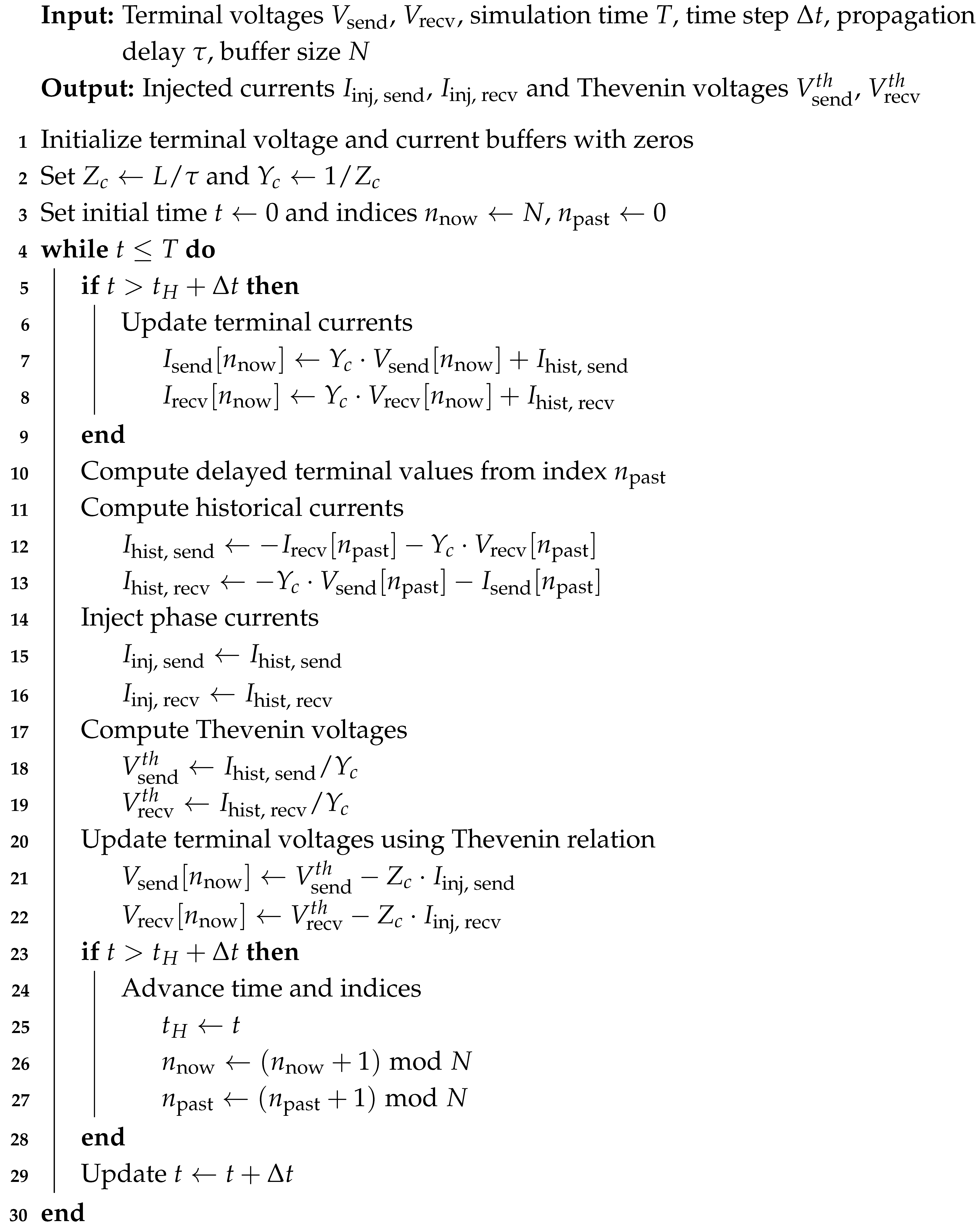
Thus, inductance can be determined using this approach, enabling the precise control of inductive effects without the need for additional physical inductors in the simulation. Additionally, we assume that the wave propagation delay corresponds to the speed of light, as power system networks primarily consist of overhead transmission lines. The algorithm in Algorithm 1 computes the current injection values at both the sending and receiving ends of the ideal Bergeron model by using delayed modal voltage and current history buffers. The model assumes a lossless line characterized by a fixed propagation delay and characteristic impedance, and it updates current injections and Thevenin-equivalent voltages at every simulation step. The implementation procedure of the ideal Bergeron model for single-phase current injection is summarized in Algorithm 1. The algorithm operates on a time-stepped basis and uses a circular buffer to store modal voltages and modal currents for both the sending and receiving ends. At each time step, the modal voltages are updated and used to compute the corresponding modal currents, which include contributions from the previous wave propagation history. The historical current terms are calculated based on a fixed propagation delay and are then used to determine the current injections at both terminals of the emulated transmission line. Additionally, Thevenin-equivalent voltages are computed and supplied to the external simulator interface to ensure correct voltage continuity. By advancing the time index and cyclically updating the buffers, the algorithm maintains a physically consistent traveling-wave response, suitable for use in EMT-based real-time simulation platforms.
Algorithm 1: Single-Phase Current Injection Algorithm Based on Ideal Bergeron Model.
Sustainability 17 06690 i001

2.2.2. Practical Implementation of Converter-Based Power Line Emulation

In power system emulation, travel time delay is a crucial parameter for accurately modeling transmission line behavior. The Bergeron transmission line model incorporates this delay to simulate wave propagation effects, which significantly impact grid strength emulation and transient response analysis. To ensure practical applicability in real-time testing, we define a fixed wave propagation delay that aligns with the system’s computational framework while maintaining the physical characteristics of transmission lines. The fixed delay is determined on the basis of the power line emulation converter (PLEC) sample time (or control period) and buffer size, allowing a streamlined and consistent emulation process. We assume that the PLEC sampling time ( T s ) is 10 μ s and the buffer size (N) is 10. Then, the fixed delay (wave propagation delay) is obtained as a result of Equation (14):
τ = N × T s = 10 × 10 μ s = 0.1 ms
where the following abbreviations are used:
  • τ = Traveling time delay [s];
  • N= Buffer size (number of stored data points);
  • T s = Sampling time per step [s].
Thus, the fixed traveling time delay of our PLEC is set to 0.1 ms.

2.2.3. Determination of Characteristic Impedance Based on Short-Circuit Ratio

In power system emulation, accurately modeling different grid conditions is essential to evaluate the performance of grid-forming converters. The short-circuit ratio (SCR) serves as a key impedance of the grid. A high SCR value indicates a strong grid, where voltage stability remains largely unaffected by power fluctuations. In contrast, a low SCR value characterizes a weak grid, where the stability of the system is dependent on the converter’s ability to regulate voltage and frequency. To represent grid conditions associated with a given SCR, the converter-based power line emulator adjusts its characteristic impedance. This section will present how Z C is derived from the SCR.

2.2.4. Thévenin Equivalent Representation in Grid Emulation

A power system can be approximated using a Thévenin equivalent circuit, where the grid is modeled as an ideal voltage source ( V P C C ) in series with an equivalent impedance ( Z g ). This grid impedance defines short-circuit characteristics at the point of common coupling (PCC) and determines the strength of the network.
The short circuit ratio (SCR) is defined in Equation (15) as follows:
S C R = S s c S r a t e d
where the following abbreviations are used:
  • S s c is the short-circuit capacity at the PCC [VA];
  • S r a t e d is the rated power of the converter [VA].
A high SCR (SCR > 5) represents a strong grid, where voltage fluctuations are minimal. A low SCR (SCR < 2) characterizes a weak grid, where voltage and frequency stability are highly dependent on the converter’s control strategies. Then we can derive the relationship between SCR and characteristic impedance.
The short-circuit capacity of the PCC is related to the system voltage and the impedance of the grid as shown in Equation (16):
S s c = V P C C 2 Z g
By substituting this into Equation (15), we can express the equivalent grid impedance as shown in Equation (17):
Z g = V P C C 2 S C R × S r a t e d
Since the transmission line’s characteristic impedance is a function of the Thévenin equivalent impedance, we can approximate the equivalent inductance of the network Equations (18) and (19) as follows:
Z g = V P C C 2 S C R × S r a t e d = ω L g
L g = V P C C 2 S C R × S r a t e d × ω
where L g is total inductance of the power grid.

2.2.5. Determination of Characteristic Impedance with Fixed Propagation Delay

From Equations (12) and (13), the characteristic impedance is obtained from Equations (20) and (21):
Z C = L × ϖ
Z C = L × d τ = L g τ = V P C C 2 S C R × S r a t e d × ω × τ
By defining a fixed propagation delay, we ensure a uniform alignment of the time steps with the computational framework of the system. To practically implement this approach, the simulation parameters are selected considering the characteristics of a power converter. A fixed propagation delay of 0.1 ms is applied to ensure an accurate representation of wave propagation dynamics. The system’s sampling time is set to 10 μ s, taking into account the specifications of contemporary converters. With advancements in SiC (Silicon Carbide) semiconductor technology, switching frequencies of up to 20 kHz are possible, and the enhanced performance of modern controllers allows for precise operation at these high frequencies. Furthermore, a buffer size of 10 is chosen to align with the fixed propagation delay and sampling time, ensuring efficient data processing while maintaining computational stability.

2.3. Power Converter-Based Line Emulation Model Validation with Simple Test Case

2.3.1. Ideal Model

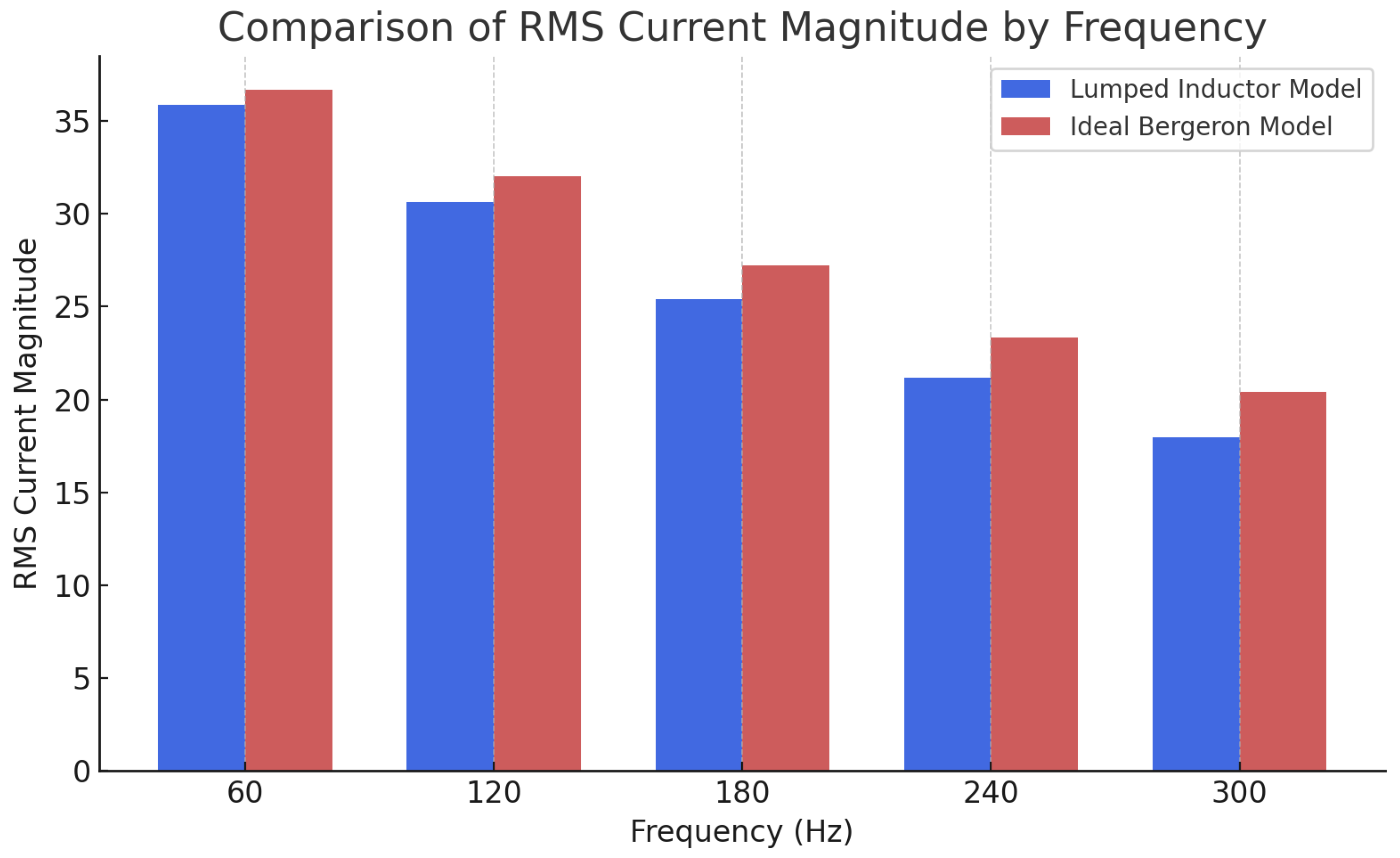
To validate the model while minimizing the influence of the capacitance of the model, a fixed propagation delay of 0.01 ms, a sampling time of 0.1 μ s, and a buffer size of 100 are applied to a simple test system, as illustrated in Figure 2. The test circuit consists of two single-phase 220 V AC voltage sources with a phase difference of 10 degrees between them, each having a resistive impedance of 0.5 Ω , and connected through a 1 mH inductor. The power line simulation model has two separate inductors of 250 μ H, because the converter has an inductance filter. Thus, the power line simulation model will present a 500 μ H inductance of the power line, which corresponds to a characteristic impedance of 50 Ω . The result is shown in Figure 3. The maximum current in the lumped inductor test circuit is measured as 50.75 A at both the sending end and the receiving end. In contrast, in the power line simulation model, the maximum current is observed to be 50.61 A at the sending end and 50.64 at the receiving end. These results demonstrate the ability of the model to emulate the transient behavior of the transmission line effectively while maintaining a realistic impedance profile. Furthermore, the emulator’s accuracy is evaluated in the frequency domain by applying sinusoidal voltages from 60 Hz to 300 Hz and comparing the RMS current magnitudes with those of the lumped inductor model. As presented in Figure 4 and Table 1, the deviation remains small at lower frequencies (2.26% at 60 Hz) and gradually increases with frequency, reaching 13.5% at 300 Hz. This increasing deviation is primarily attributed to the fact that the ideal Bergeron model includes distributed capacitance, which becomes more significant at higher frequencies. Despite this limitation, the emulator maintains an acceptable accuracy within the frequency range relevant to power system applications.

2.3.2. Non-Ideal Model

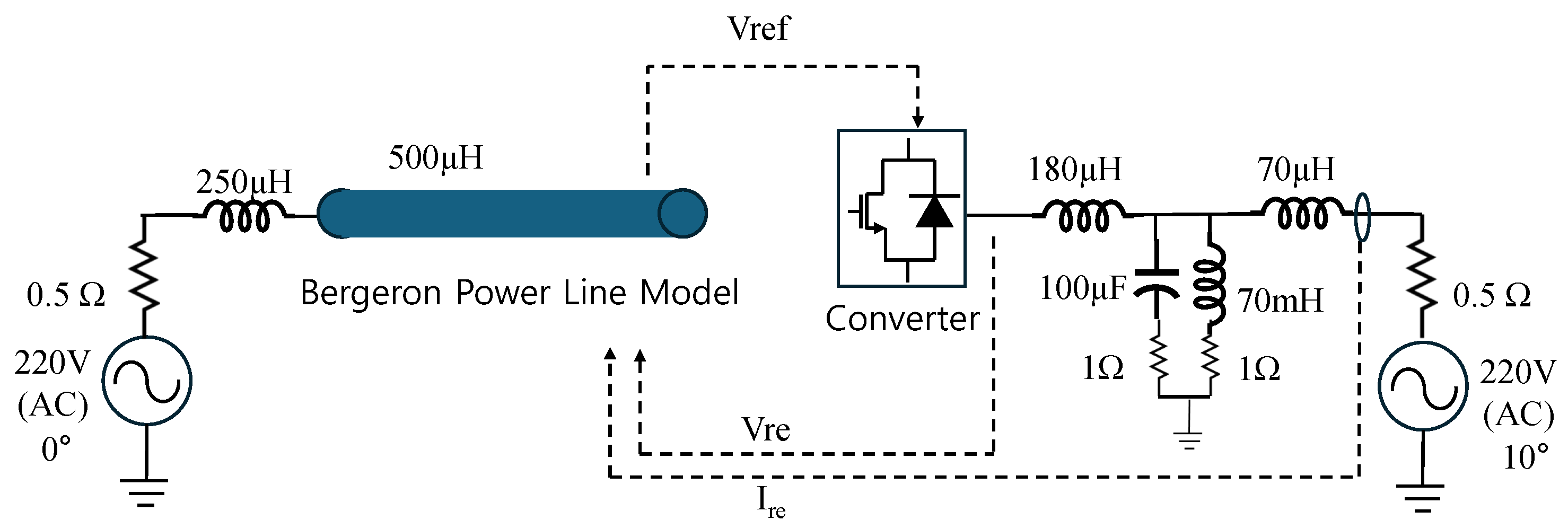
For a non-ideal model, a converter is implemented in the test circuit, as shown in Figure 5. For a simplified test setup, only the receiving end was replaced with a converter. We set a fixed propagation delay of 0.1 ms, a sampling time of 10 μ s, and a buffer size of 10 is applied to the test system. The characteristic impedance is set to 5 Ω corresponding to 500 μ H of the test line. The converter specification is shown in Table 2.
The result is shown in Figure 6. Due to the nature of the converter-based power line emulator, high-frequency switching currents can be observed on the converter side. However, when analyzed using a low-pass filter with a time constant of 1 ms, the magnitude of the AC current is 53.3 A. On the grid side, the maximum current magnitude is 53.3 A.

3. Grid-Forming Converter Test with Proposed Power Converter-Based Line Emulation Model: Phase Jump Test

3.1. Simulation Conditions

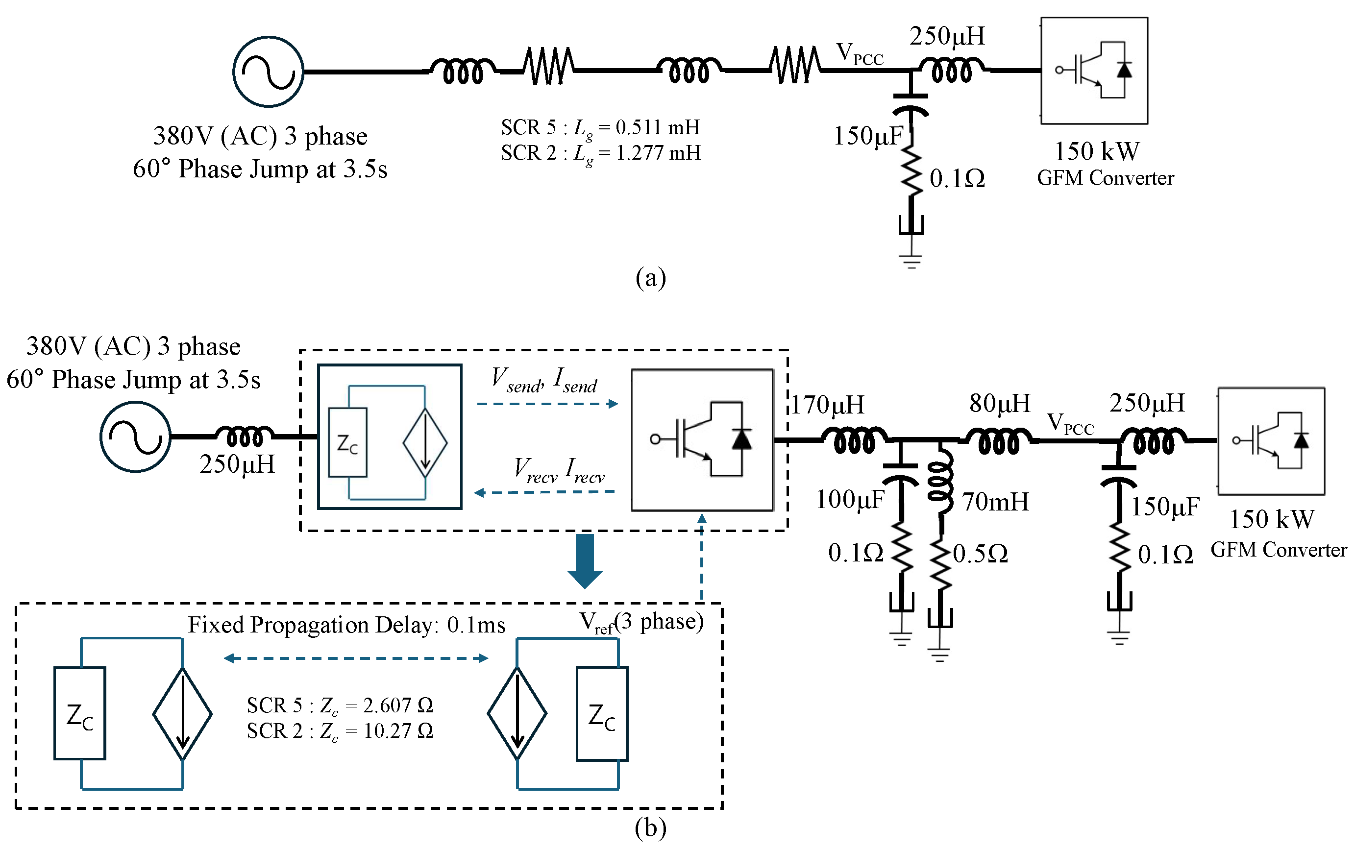
In this study, a phase jump test is performed to assess the transient response of a 150 kW GFM converter under various grid conditions. Unlike the previous single-phase test circuit, this experiment is configured in a three-phase system. The test setup consists of an ideal voltage source at the sending end, while the receiving end incorporates a GFM converter model, operating under different grid strengths simulated by the proposed converter-based power line emulator, as shown in Figure 7. This configuration enables the investigation of the ability of the GFM converter to maintain synchronization and voltage stability in response to abrupt phase changes in grid voltage. The tested GFM converter is a three-phase, two-level voltage source converter with a power output rated at 150 kW and an AC line-to-line voltage of 380 V. The specifications of the converter are summarized in Table 3. The power line emulator is configured to provide an adjustable characteristic impedance and fixed propagation delay, ensuring a controlled and repeatable testing environment, and the converter specifications are summarized in Table 4.
The phase jump test is conducted under two different short-circuit ratio (SCR) conditions: SCR 2 and SCR 5. The SCR values are determined based on a base voltage of 380 V and a rated power of 150 kW, resulting in corresponding grid impedance of 0.48133 Ω and 0.192533 Ω , respectively. The inductance of the converter-side filter is excluded when setting the impedance of the emulator to accurately represent the desired grid conditions. This configuration enables a controlled evaluation of the performance of the GFM converter under strong and weak grid conditions. The characteristic impedance, propagation delay, and sampling time for different SCR conditions are summarized in Table 5. This table provides a clear reference for the test conditions used to evaluate the performance of the GFM converter under various grid strengths.

3.2. Simulation Results

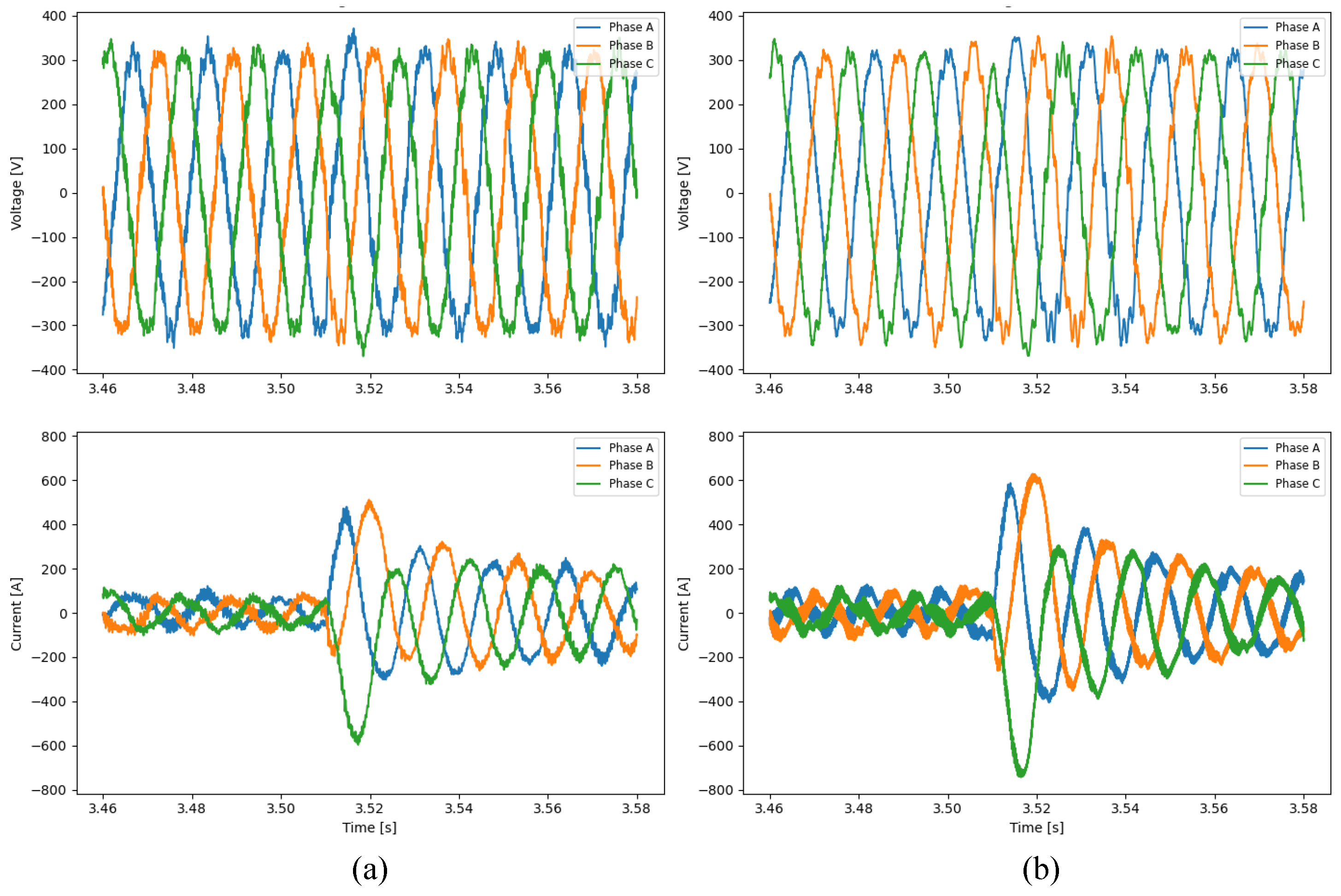
To evaluate the performance of the proposed power line emulation model, a phase jump test was performed using both a lumped impedance model and the proposed power line emulator. The test conditions included a 60-degree phase jump while the GFM converter maintained an initial active power of zero and regulated reactive power based on its droop characteristics.
The voltage and current responses at the point of interconnection (POI) for the lumped impedance model and the power line emulation converter are presented in Figure 8 and Figure 9, respectively.
As observed in Figure 8 and Figure 9, current responses during the phase jump exhibit similarities between the lumped impedance model and the power line emulation model, depending on the short-circuit ratio (SCR). The transient behavior, including the magnitude and settling characteristics of the current waveform, shows only a minimal deviation between the two models. It is worth noting that the power line emulation model produces higher current levels than the lumped inductor line model because of a capacitive filter. The filters in both the power line emulation converter and the GFM converter contribute reactive currents. These results demonstrate that the proposed power line emulator reasonably emulates the dynamic response of a lumped impedance model under various impedance conditions.

4. Conclusions

The increasing penetration of inverter-based resources in power systems has led to a reduction in conventional synchronous inertia and short-circuit strength, posing new challenges for maintaining system stability. Grid-forming (GFM) converters have emerged as a promising solution to address challenges, offering improved voltage and frequency stability, particularly in weak-grid conditions. However, the testing and validation of GFM converters remain a critical issue due to the limitations of traditional power system emulation methods. This paper introduced a converter-based power line emulator as an effective and scalable solution to evaluate GFM converters under varying grid strength conditions. Unlike traditional test facilities, which are often constrained by fixed voltage control, the proposed emulator will provide a programmable test environment. By leveraging power electronics and digital control techniques, this emulator enables the power line emulation of different grid conditions, ranging from strong high-inertia systems to weak grids, while also allowing for controlled fault injections and transient event simulations. Through detailed PSCAD-based simulations to validate the power line emulator algorithm, the proposed solution will bridge the gap between simulations and full-scale field tests. The results indicate that this emulator will provide a cost-effective, flexible, and scalable alternative, allowing researchers and industry professionals to evaluate the performance of the GFM converter more efficiently and under a broader range of conditions. To validate its performance, both steady-state and transient behaviors were examined under representative grid strength scenarios, specifically SCR = 2 (weak grid) and SCR = 5 (strong grid). Time-domain comparisons confirmed that the emulator reproduces the behavior of conventional lumped impedance models. It is worth noting that the proposed approach offers a deterministic framework for representing grid strength through fixed propagation delay and characteristic impedance. Future work will focus on experimental validation of the proposed emulator using real hardware setups, expanding its capabilities to accommodate multiple interconnected GFM converters and exploring advanced control strategies to ensure stable operation in multi-converter environments. In addition, integration with real-time HIL platforms will be investigated to further enhance accuracy and applicability for grid compliance testing and certification. Ultimately, the proposed converter-based power line emulator represents a critical advancement in GFM converter testing methodologies, enabling the more robust, repeatable, and cost-efficient evaluation of next-generation power electronics-based systems. Its deployment will contribute to the reliable and secure integration of GFM converters in future power grids, supporting the transition toward high-renewable, low-inertia, and DER-dominant power systems.

Author Contributions

Conceptualization, C.-S.H., Y.-W.Y., H.-K.C. and T.-J.K.; methodology, C.-S.H., Y.-W.Y., H.-K.C. and T.-J.K.; software, C.-S.H.; validation, Y.-W.Y. and T.-J.K.; formal analysis, C.-S.H.; investigation, C.-S.H., Y.-W.Y., H.-K.C. and T.-J.K.; resources, C.-S.H.; data curation, C.-S.H.; writing—original draft preparation, C.-S.H.; writing—review and editing, C.-S.H., Y.-W.Y., H.-K.C. and T.-J.K.; visualization, C.-S.H.; supervision, Y.-W.Y., H.-K.C. and T.-J.K.; project administration, T.-J.K. All authors have read and agreed to the published version of the manuscript.

Funding

This work was supported by the Power Generation and Electricity Delivery Core Technology Program of the Korea Institute of Energy Technology Evaluation and Planning (KETEP), granted financial resources from the Ministry of Trade, Industry and Energy, Republic of Korea (No. RS-2023-00321745). This research was supported by the Korea Electrotechnology Research Institute (KERI) Primary research program through the National Research Council of Science and Technology (NST), funded by the Ministry of Science and ICT (MSIT) (No. 25A01024).

Institutional Review Board Statement

Not applicable.

Informed Consent Statement

Not applicable.

Data Availability Statement

All data are contained within this article.

Conflicts of Interest

The authors declare no conflicts of interest.

References

  1. Matevosyan, J.; Badrzadeh, B.; Prevost, T.; Quitmann, E.; Ramasubramanian, D.; Urdal, H.; Achilles, S.; MacDowell, J.; Huang, S.H.; Vital, V.; et al. Grid-Forming Inverters: Are They the Key for High Renewable Penetration? IEEE Power Energy Mag. 2019, 17, 89–98. [Google Scholar] [CrossRef]
  2. Al-Shetwi, A.Q.; Hannan, M.; Jern, K.P.; Mansur, M.; Mahlia, T. Grid-connected renewable energy sources: Review of the recent integration requirements and control methods. J. Clean. Prod. 2020, 253, 119831. [Google Scholar] [CrossRef]
  3. California Independent System Operator. What the Duck Curve Tells Us About Managing a Green Grid; California Independent System Operator: Folsom, CA, USA, 2016. [Google Scholar]
  4. ISO New England. Solar Power in New England: Concentration and Impact; ISO New England: Holyoke, MA, USA, 2017. [Google Scholar]
  5. Wilkinson, S.; Maticka, M.J.; Liu, Y.; John, M. The duck curve in a drying pond: The impact of rooftop PV on the Western Australian electricity market transition. Util. Policy 2021, 71, 101232. [Google Scholar] [CrossRef]
  6. Hou, Q.; Zhang, N.; Du, E.; Miao, M.; Peng, F.; Kang, C. Probabilistic duck curve in high PV penetration power system: Concept, modeling, and empirical analysis in China. Appl. Energy 2019, 242, 205–215. [Google Scholar] [CrossRef]
  7. Lew, D.; Asano, M.; Boemer, J.; Ching, C.; Focken, U.; Hydzik, R.; Lange, M.; Motley, A. The power of small: The effects of distributed energy resources on system reliability. IEEE Power Energy Mag. 2017, 15, 50–60. [Google Scholar] [CrossRef]
  8. Huber, M.; Dimkova, D.; Hamacher, T. Integration of wind and solar power in Europe: Assessment of flexibility requirements. Energy 2014, 69, 236–246. [Google Scholar] [CrossRef]
  9. Notton, G.; Nivet, M.-L.; Voyant, C.; Paoli, C.; Darras, C.; Motte, F.; Fouilloy, A. Intermittent and stochastic character of renewable energy sources: Consequences, cost of intermittence and benefit of forecasting. Renew. Sustain. Energy Rev. 2018, 87, 96–105. [Google Scholar] [CrossRef]
  10. Kroposki, B.; Johnson, B.; Zhang, Y.; Gevorgian, V.; Denholm, P.; Hodge, B.M.; Hannegan, B. Achieving a 100% Renewable Grid: Operating Electric Power Systems with Extremely High Levels of Variable Renewable Energy. IEEE Power Energy Mag. 2017, 15, 61–73. [Google Scholar] [CrossRef]
  11. Australian Energy Market Operator (AEMO). Technical Integration of Distributed Energy Resources; Technical Report; AEMO: Melbourne, Australia, 2019. [Google Scholar]
  12. Kim, J.K.; Lee, S.; Kim, J.S.; Choi, H. The Need for Modeling the Impact of Behind-the-Meter Generation Trip on Primary Frequency Response Through Operational Experiences in Korea Power System. IEEE Trans. Power Syst. 2022, 37, 1661–1664. [Google Scholar] [CrossRef]
  13. Kim, S.; Lee, H.; Kim, H.; Jang, D.H.; Kim, H.J.; Hur, J.; Cho, Y.S.; Hur, K. Improvement in policy and proactive interconnection procedure for renewable energy expansion in South Korea. Renew. Sustain. Energy Rev. 2018, 98, 150–162. [Google Scholar] [CrossRef]
  14. Kim, J.K.; Kang, J.; Shim, J.W.; Kim, H.; Shin, J.; Kang, C.; Hur, K. Dynamic performance modeling and analysis of power grids with high levels of stochastic and power electronic interfaced resources. Proc. IEEE 2023, 111, 854–872. [Google Scholar] [CrossRef]
  15. Kim, H.; Kim, S.; Chung, Y.H.; Yoo, D.W.; Kim, C.K.; Hur, K. Operating region of modular multilevel converter for HVDC with controlled second-order harmonic circulating current: Elaborating PQ capability. IEEE Trans. Power Deliv. 2015, 31, 493–502. [Google Scholar] [CrossRef]
  16. Kim, H.; Kang, J.; Shim, J.W.; Beerten, J.; Van Hertem, D.; Jung, H.J.; Kim, C.K.; Hur, K. Exploiting redundant energy of MMC–HVDC to enhance frequency response of low inertia AC grid. IEEE Access 2019, 7, 138485–138494. [Google Scholar] [CrossRef]
  17. Kim, H.; Kim, J.K.; Song, J.; Lee, J.; Han, K.; Shin, J.; Kim, T.; Hur, K. Smart and green substation: Shaping the electric power grid of Korea. IEEE Power Energy Mag. 2019, 17, 24–34. [Google Scholar] [CrossRef]
  18. Shim, J.W.; Verbič, G.; Kim, H.; Hur, K. On droop control of energy-constrained battery energy storage systems for grid frequency regulation. IEEE Access 2019, 7, 166353–166364. [Google Scholar] [CrossRef]
  19. Xu, B.; Gao, C.; Zhang, J.; Yang, J.; Xia, B.; He, Z. A Novel DC Chopper Topology for VSC-Based Offshore Wind Farm Connection. IEEE Trans. Power Electron. 2021, 36, 3017–3027. [Google Scholar] [CrossRef]
  20. Erlich, I.; Shewarega, F.; Engelhardt, S.; Kretschmann, J.; Fortmann, J.; Koch, F. Effect of wind turbine output current during faults on grid voltage and the transient stability of wind parks. In Proceedings of the 2009 IEEE Power and Energy Society General Meeting, Calgary, AB, Canada, 26–30 July 2009; pp. 1–8. [Google Scholar] [CrossRef]
  21. Christensen, P.; Andersen, G.K.; Seidel, M.; Bolik, S.; Engelken, S.; Knueppel, T.; Krontiris, A.; Wuerflinger, K.; Bülo, T.; Jahn, J.; et al. High Penetration of Power Electronic Interfaced Power Sources and the Potential Contribution of Grid Forming Converters; University of Strathclyde: Glasgow, UK, 2020. [Google Scholar]
  22. Lasseter, R.H.; Chen, Z.; Pattabiraman, D. Grid-Forming Inverters: A Critical Asset for the Power Grid. IEEE J. Emerg. Sel. Top. Power Electron. 2020, 8, 925–935. [Google Scholar] [CrossRef]
  23. Denis, G.; Prevost, T.; Debry, M.; Xavier, F.; Guillaud, X.; Menze, A. The Migrate project: The challenges of operating a transmission grid with only inverter-based generation. A grid-forming control improvement with transient current-limiting control. IET Renew. Power Gener. 2018, 12, 523–529. [Google Scholar] [CrossRef]
  24. IEEE 2800-2022; IEEE Standard for Interconnection and Interoperability of Inverter-Based Resources (IBRs) Interconnecting with Associated Transmission Electric Power Systems. IEEE: Piscataway, NJ, USA, 2022.
  25. 50Hertz; Ampiron; TenneT; TransnetBW. 4-TSO Paper on Requirements for Grid-Forming Converters. 2022. Available online: https://www.netztransparenz.de/xspproxy/api/staticfiles/ntp-relaunch/dokumente/zuordnung_unklar/grundlegende-anforderungen-an-netzbildende-umrichter/220504_-_4-tso_paper_on_requirements_for_grid-forming_converters.pdf (accessed on 30 May 2024).
  26. FinGrid. Grid Code Specifications for Grid Energy Storage Systems SJV2019; FinGrid: Helsinki, Finland, 2020. [Google Scholar]
  27. IEC 61400-21-2:2023; Wind Energy Generation Systems—Part 21-4: Wind Turbine Components and Subsystems. International Electrotechnical Commission: Geneva, Switzerland, 2023.
  28. ENTSO-E; Wind Europe; Solar Power Europe; T&D Europe. High Penetration of Power Electronic Interfaced Power Sources (HPoPEIPS). 2017. Available online: https://consultations.entsoe.eu/system-development/entso-e-connection-codes-implementation-guidance-d-3/user_uploads/igd-high-penetration-of-power-electronic-interfaced-power-sources.pdf (accessed on 30 May 2024).
  29. Australian Energy Market Operator. Voluntary Specification for Grid-Forming Inverters. 2023. Available online: https://aemo.com.au/-/media/files/initiatives/primary-frequency-response/2023/gfm-voluntary-spec.pdf (accessed on 30 May 2024).
  30. Australian Energy Market Operator. Voluntary Specification for Grid-Forming Inverters: Core Requirements Test Framework. 2024. Available online: https://aemo.com.au/-/media/files/initiatives/engineering-framework/2023/grid-forming-inverters-jan-2024.pdf?la=en&hash=7778A2249D8C29A95A2FADCD9AAA509D (accessed on 15 October 2024).
  31. National Grid ESO. Stability Pathfinder Oct 2019, Draft Grid CODE Grid Forming and Request for Information Feedback. 2019. Available online: https://www.neso.energy/document/185306/download (accessed on 30 May 2024).
  32. GC0137; Minimum Specification Required for Provision of GB Grid Forming (GBGF) Capability (Formerly Virtual Synchronous Machine/VSM Capability). National Grid ESO: Wokingham, UK, 2021.
  33. National Grid ESO. Great Britain Grid Forming Best Practice Guide. 2023. Available online: https://www.studocu.com/pt-br/document/escola-universitaria-universidade-federal-do-rio-de-janeiro/ciencias/great-britain-grid-forming-best-practices-guide-april-2023/92650440 (accessed on 30 May 2024).
  34. National Grid ESO. System Oscillation Assessment of Inverter Based Resources (IBRs). 2024. Available online: https://www.neso.energy/document/301686/download (accessed on 30 May 2024).
  35. Aljarrah, R.; Fawaz, B.B.; Salem, Q.; Karimi, M.; Marzooghi, H.; Azizipanah-Abarghooee, R. Issues and Challenges of Grid-Following Converters Interfacing Renewable Energy Sources in Low Inertia Systems: A Review. IEEE Access 2024, 12, 5534–5561. [Google Scholar] [CrossRef]
  36. Barthelmie, R.J.; Pryor, S.C. Climate Change Mitigation Potential of Wind Energy. Climate 2021, 9, 136. [Google Scholar] [CrossRef]
  37. Curran, O.; Guerreiro, G.M.G.; Azarian, S.; Martin, F.; Dreyer, T. WTG Manufacturer’s Experience with Subsystem and Component Validation for Wind Turbines. In Proceedings of the 21st Wind & Solar Integration Conference, The Hague, The Netherlands, 12–14 October 2022; pp. 458–465. [Google Scholar]
  38. Expert Group: Advanced Capabilities for Grids with a High Share of Power Park Modules. 2023. Available online: https://eepublicdownloads.blob.core.windows.net/public-cdn-container/clean-documents/Network%20codes%20documents/GC%20ESC/GC%20ESC%20MEETING%20DOCS/2023/ACCPM_Report_Draft_0.9_.pdf (accessed on 30 May 2024).
  39. Energinet. Classification: Public Technical Regulation 3.2.5 for Wind Power Plants Above 11 kW. 2016. Available online: https://en.energinet.dk/media/5pbflmly/technical-regulation-325-for-wind-power-plants-above-11-kw-revision-4.pdf (accessed on 30 May 2024).
  40. Electric Power Research Institute. Grid Forming Inverters: EPRI Tutorial. 2023. Available online: https://www.epri.com/research/products/000000003002028090 (accessed on 30 May 2024).
  41. Energy Systems Integration Group. Grid-Forming Technology in Energy Systems Integration, High Share of Inverter-Based Generation Task Force. 2022. Available online: https://www.esig.energy/wp-content/uploads/2022/03/ESIG-GFM-report-2022.pdf (accessed on 30 May 2024).
  42. FinGrid. Specific Study Requirements for Grid Energy Storage Systems; FinGrid: Helsinki, Finland, 2023. [Google Scholar]
  43. Gevorgian, V.; Koralewicz, P.; Shah, S.; Yan, W.; Wallen, R.; Mendiola, E. Testing GFM and GFL Inverters Operating with Synchronous Condensers. In Proceedings of the 2023 IEEE Power and Energy Society General Meeting, Orlando, FL, USA, 16–20 July 2023; pp. 1–5. [Google Scholar] [CrossRef]
  44. Ghime, S.; Amico, G.; Kkuni, K.V.; Guerreiro, G.M.G.; Jensen, K.H.; Yang, G. Enabling Islanding and Re-Synchronization of Grid-Forming Offshore Wind Turbine Generators. In Proceedings of the 22nd Wind and Solar Integration Workshop, Helsinki, Finland, 8–11 October 2024. [Google Scholar]
  45. Gomes Guerreiro, G.M.; Sharma, R.; Martin, F.; Ghimire, P.; Yang, G. Concerning Short-Circuit Current Contribution Challenges of Large-Scale Full-Converter Based Wind Power Plants. IEEE Access 2023, 11, 64141–64159. [Google Scholar] [CrossRef]
  46. Gomes Guerreiro, G.M.; Martin, F.; Dreyer, T.; Yang, G.; Andresen, B. Advancements on Grid Compliance in Wind Power: Component & Subsystem Testing, Software-/Hardware-in-the-Loop, and Digital Twins. IEEE Access 2024, 12, 25949–25966. [Google Scholar] [CrossRef]
  47. Hans, F.; Curioni, G.; Jersch, T.; Quistorf, G.; Ruben, M.; Müller, A.; Wessels, C.; Fenselau, C.; Prima, I.; Lehmann, J. Towards Full Electrical Certification of Wind Turbines on Test Benches—Experiences Gained from the HiL-GridCoP Project. In Proceedings of the 21st Wind & Solar Integration Workshop, The Hague, The Netherlands, 12–14 October 2022; pp. 122–129. [Google Scholar] [CrossRef]
  48. Hans, F.; Quistorf, G.; Jersch, T.; Chekavskyy, G.; Bujak, G.; Sobanski, P.; Eckerle, J. Mobil-Grid-CoP—A New Approach for Grid Compliance Testing on Multimegawatt Wind Turbines in Field. In Proceedings of the 22nd Wind & Solar Integration Workshop, Copenhagen, Denmark, 26–28 September 2023. [Google Scholar]
  49. InterOPERA Consortium. Grid-Forming Functional Requirements for HVDC Converter Stations and DC-Connected PPMs in Multi-Terminal Multi-Vendor HVDC Systems. 2024. Available online: https://interopera.eu/wp-content/uploads/files/deliverables/InterOPERA-D2.2-GFM-functional-requirements-202401.pdf (accessed on 30 May 2024).
  50. Johansen, K. Grid Codes: Recommendations for Connection of Offshore Wind Power Energinet; Energinet Associated Activities: Fredericia, Denmark, 2020. [Google Scholar]
  51. Li, Z.; Wang, X.; Zhao, F.; Munk-Nielsen, S.; Geske, M.; Grune, R.; Andersen, D.B.R.; Rodriguez, M.G. Power-Hardware Design and Topologies of Converter-Based Grid Emulators for Wind Turbines. IEEE J. Emerg. Sel. Top. Power Electron. 2023, 11, 5001–5017. [Google Scholar] [CrossRef]
  52. Lyu, X.; Groß, D. Grid Forming Fast Frequency Response for PMSG-Based Wind Turbines. IEEE Trans. Sustain. Energy 2024, 15, 23–38. [Google Scholar] [CrossRef]
  53. Milano, F.; Dörfler, F.; Hug, G.; Hill, D.J.; Verbič, G. Foundations and Challenges of Low-Inertia Systems (Invited Paper). In Proceedings of the 2018 Power Systems Computation Conference (PSCC), Dublin, Ireland, 11–15 June 2018; pp. 1–25. [Google Scholar] [CrossRef]
  54. Musca, R.; Vasile, A.; Zizzo, G. Grid-forming converters. A critical review of pilot projects and demonstrators. Renew. Sustain. Energy Rev. 2022, 165, 112551. [Google Scholar] [CrossRef]
  55. National Grid. Onshore vs. Offshore Wind Energy. 2023. Available online: https://www.nationalgrid.com/stories/energy-explained/onshore-vs-offshore-wind-energy (accessed on 30 May 2024).
  56. North American Electric Reliability Corporation. Grid Forming Technology: Bulk Power System Reliability Considerations. 2021. Available online: https://www.nerc.com/comm/RSTC_Reliability_Guidelines/White_Paper_Grid_Forming_Technology.pdf (accessed on 30 May 2024).
  57. North American Electric Reliability Corporation. White Paper: Grid Forming Functional Specifications for BPS-Connected Battery Energy Storage Systems. 2023. Available online: https://www.nerc.com/comm/RSTC_Reliability_Guidelines/White_Paper_GFM_Functional_Specification.pdf (accessed on 30 May 2024).
  58. Neshati, M.; Azarian, S.; Curran, O.; Pillai, R.; Due, J.; Guest, E.; Freire, N.; Dreyer, T.; Martin, F. Grid Connection Testing of Wind Energy Converters with Medium Voltage Generator- and Grid Emulation on a Multi-Megawatt Power-Hardware-in-the-Loop Test Rig. In Proceedings of the 22nd Wind & Solar Integration Workshop, Copenhagen, Denmark, 26–28 September 2023. [Google Scholar] [CrossRef]
  59. OSMOSE. D3.3 Analysis of the Synchronisation Capabilities of BESS Power Converters. 2021. Available online: https://www.osmose-h2020.eu/wp-content/uploads/2022/04/D3.3-Analysis-of-the-synchronisation-capabilities-of-BESS-power-converters.pdf (accessed on 30 May 2024).
  60. Pattabiraman, D.; Lasseter, R.H.; Jahns, T.M. Comparison of Grid Following and Grid Forming Control for a High Inverter Penetration Power System. In Proceedings of the 2018 IEEE Power and Energy Society General Meeting, Portland, OR, USA, 5–10 August 2018; pp. 1–5. [Google Scholar] [CrossRef]
  61. Rokrok, E.; Qoria, T.; Bruyere, A.; Francois, B.; Guillaud, X. Integration of a storage device to the DC bus of a grid-forming controlled HVDC interconnection. Electr. Power Syst. Res. 2022, 212, 108601. [Google Scholar] [CrossRef]
  62. TenneT. Grid Connection Requirements for DC Connected PPMs, System Needs and Functions, Annex C.2.300. 2023. Available online: https://www.tennet.eu/de/strommarkt/kunden-deutschland/netzkunden/netzanschlussregeln (accessed on 30 May 2024).
  63. UNIFI Consortium. UNIFI Specifications for Grid-Forming Inverter-Based Resources—Version 2, UNIFI-2024-2-1. 2022. Available online: https://docs.nrel.gov/docs/fy24osti/89269.pdf (accessed on 30 March 2024).
  64. U.S. Energy Information Administration. Table 1.1. Net Generation by Energy Source: Total (All Sectors). 2023. Available online: https://www.eia.gov/electricity/annual/html/epa_01_01.html (accessed on 18 March 2024).
  65. VDE FNN. FNN Guideline: Grid Forming Behavior of HVDC Systems and DC-Connected PPMs. 2020. Available online: https://www.vde.com/en/fnn/dokumente-en (accessed on 30 May 2024).
  66. Tamura, Y.; Dan, E.; Morie, I.; Nakanishi, Y.; Yokokawa, S. Development of Power System Simulator for Research and Education. IEEE Trans. Power Syst. 1990, 5, 492–499. [Google Scholar] [CrossRef]
  67. Parizad, A.; Mohamadian, S.; Iranian, M.E.; Guerrero, J.M. Power System Real-Time Emulation: A Practical Virtual Instrumentation to Complete Electric Power System Modelling. IEEE Trans. Power Electron. 2023, 15, 889–900. [Google Scholar] [CrossRef]
  68. Zhang, S.; Liu, B.; Zheng, S.; Ma, Y.; Wang, F.; Tolbert, L.M. Development of a Converter-Based Transmission Line Emulator with Three-Phase Short-Circuit Fault Emulation Capability. IEEE Trans. Power Electron. 2018, 33, 10215–10228. [Google Scholar] [CrossRef]
  69. Dommel, H.W. Digital computer solution of electromagnetic transients in single- and multi-phase networks. IEEE Trans. Power Appar. Syst. 1969, 88, 734–741. [Google Scholar] [CrossRef]
  70. Watson, N.; Arrillaga, J. Power Systems Electromagnetic Transients Simulation; Institution of Engineering and Technology (IET): Stevenage, UK, 2003. [Google Scholar]
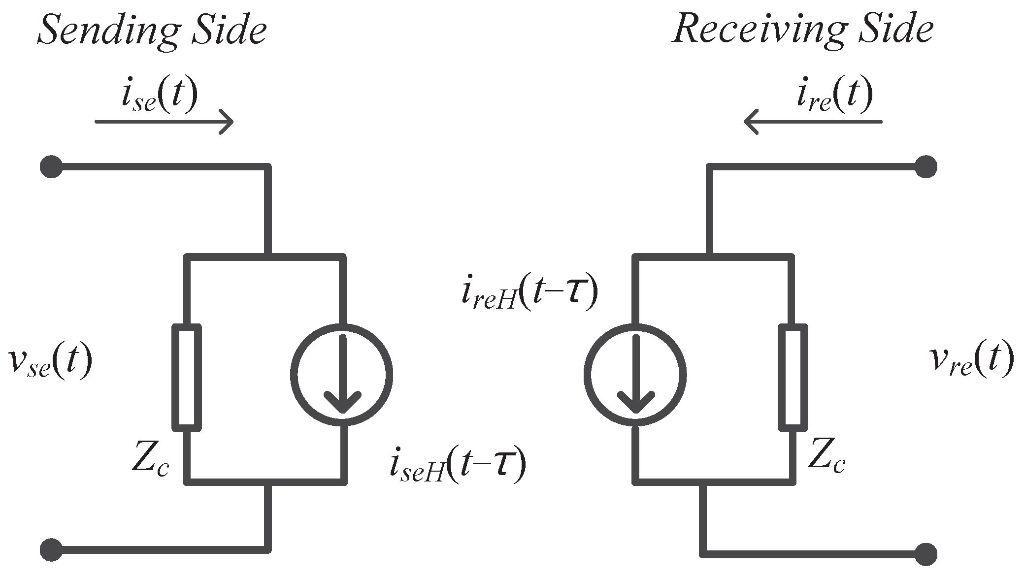
Figure 1. The simple lossless Bergeron transmission line model.
Sustainability 17 06690 g001
Figure 2. Test network for (a) lumped inductor circuit and (b) Bergeron power line model.
Sustainability 17 06690 g002
Figure 3. Current of lumped inductor test circuit and current of ideal line emulator model: (a) sending end currents; (b) receiving end currents.
Sustainability 17 06690 g003
Figure 4. A comparison of the RMS current magnitude between the lumped inductor model and the proposed emulator across various frequencies. The increasing deviation at higher frequencies is attributed to the effect of distributed capacitance in the Bergeron-based model, which limits its accuracy in representing high-frequency electromagnetic behavior.
Sustainability 17 06690 g004
Figure 5. Test network for traveling wave transmission line model with converter model.
Sustainability 17 06690 g005
Figure 6. Current of lumped inductor test circuit and current of non-ideal line emulator model: (a) converter-side current; (b) filtered converter-side current using low pass filter with 1 ms time constant; (c) grid-side current.
Sustainability 17 06690 g006
Figure 7. Test network for traveling wave transmission line model with converter model. (a) Grid Impedance Configured by Lumped Inductor Circuit. (b) Power Line Emulation Converter Represents Grid Impedance.
Sustainability 17 06690 g007
Figure 8. Voltage and current at the point of interconnection with lumped inductor: (a) 60-degree phase jump response with SCR 2; (b) 60-degree phase jump response with SCR 5.
Sustainability 17 06690 g008
Figure 9. Voltage and current at the point of interconnection with power line emulation converter: (a) 60-degree phase jump response with SCR 2; (b) 60-degree phase jump response with SCR 5.
Sustainability 17 06690 g009
Table 1. A comparison of the RMS current magnitude between the lumped inductor model and the Bergeron line model across various frequencies.
FrequencyLumped InductorBergeron Line ModelDeviation
(Hz)RMS Current (A)RMS Current (A)(%)
6035.883336.69342.258
12030.620132.05324.680
18025.401927.24107.240
24021.193923.333010.093
30017.972020.397913.498
Table 2. The parameters of power line emulation converter for simple test circuit.
Converter ParametersValue
Converter-side inductor180 [ μ H]
Grid-side inductor70 [ μ H]
Converter filter capacitor100 [ μ F]
Converter shunt inductor70 [mH]
Characteristic impedance ( Z C )5 [ Ω ]
Traveling time ( τ )0.1 [ms]
Table 3. The parameters of the GFM converter.
Converter ParametersValue
Converter-Side Inductor250 [ μ H]
Converter Filter Capacitor150 [ μ F]
Switching Frequency4 [kHz]
Control Time Period125 [ μ s]
P Droop5%
Q Droop20%
DC Voltage750 [V]
Table 4. The Parameters of the power line emulator converter.
Converter ParametersValue
Converter-Side Inductor180 [ μ H]
Grid-Side Inductor70 [ μ H]
Converter Filter Capacitor100 [ μ F]
Converter Shunt Inductor70 [mH]
Switching Frequency20 [kHz]
Control Time Period10 [ μ s]
DC Voltage1000 [V]
Table 5. System and power line emulator parameters for different SCR conditions.
ParameterSCR = 2SCR = 5
Grid Impedance ( Ω )0.481330.192533
Grid Inductance ( L g )1.277 mH0.511 mH
Power Line Inductance ( L P L )1.027 mH0.261 mH
Characteristic Impedance ( Z C )10.2677 Ω 2.607 Ω
Propagation Delay ( τ )0.1 ms0.1 ms
Sampling Time ( T s )10 μ s10 μ s
Disclaimer/Publisher’s Note: The statements, opinions and data contained in all publications are solely those of the individual author(s) and contributor(s) and not of MDPI and/or the editor(s). MDPI and/or the editor(s) disclaim responsibility for any injury to people or property resulting from any ideas, methods, instructions or products referred to in the content.