Article

Development and Performance Evaluation of Hydrophobically Modified Nano-Anti-Collapsing Agents for Sustainable Deepwater Shallow Drilling

1
State Key Laboratory of Unconventional Oil & Gas Development, China University of Petroleum (East China), Ministry of Education, Qingdao 266580, China
2
School of Petroleum Engineering, China University of Petroleum (East China), Qingdao 266580, China
3
Jiangsu Gas Storage Sub-Company, PipeChina West East Gas Pipeline Company, Zhenjiang 212000, China
4
Qingdao NMEI Group Co., Ltd., Qingdao 266000, China
5
College of Petroleum and Natural Gas Engineering, Chongqing University of Science and Technology, Chongqing 401331, China
*
Author to whom correspondence should be addressed.
Sustainability 2025, 17(15), 6678; https://doi.org/10.3390/su17156678
Submission received: 27 June 2025 / Revised: 17 July 2025 / Accepted: 17 July 2025 / Published: 22 July 2025
(This article belongs to the Special Issue Sustainability and Challenges of Underground Gas Storage Engineering)

Abstract

Sustainable deepwater drilling for oil and gas offers significant potential. In this work, we synthesized a nanoscale collapse-prevention agent by grafting didecyldimethylammonium chloride onto spherical nano-silica and characterized it using Fourier-transform infrared spectroscopy, thermogravimetric analysis, zeta-potential, and particle-size measurements, as well as SEM and TEM. Adding 1 wt% of this agent to a bentonite slurry only marginally alters its rheology and maintains acceptable low-temperature flow properties. Microporous-membrane tests show filtrate passing through 200 nm pores drops to 55 mL, demonstrating excellent plugging. Core-immersion studies reveal that shale cores retain integrity with minimal spalling after prolonged exposure. Rolling recovery assays increase shale-cutting recovery to 68%. Wettability tests indicate the water contact angle rises from 17.1° to 90.1°, and capillary rise height falls by roughly 50%, reversing suction to repulsion. Together, these findings support a synergistic plugging–adsorption–hydrophobization mechanism that significantly enhances wellbore stability without compromising low-temperature rheology. This work may guide the design of high-performance collapse-prevention additives for safe, efficient deepwater drilling.

1. Introduction

Oil and natural gas have long served as the pillars of the global energy system [1,2,3]. However, onshore high-quality conventional reservoirs have undergone extensive exploitation and entered a post-mature phase—characterized by high proven reserves and recovery rates but low remaining volumes—creating significant resource-replacement challenges [4,5,6]. To ensure medium- and long-term energy security, countries are rapidly refocusing exploration and development on deepwater, deep, and ultra-deep formations, as well as on various unconventional reservoirs [7,8,9,10,11].
Statistics indicate that about 44% of the world’s recoverable oil and gas reserves lie in waters deeper than 300 m [12,13,14], positioning deepwater and ultra-deepwater oil and gas as a burgeoning pillar of the global energy supply. With energy demand on the rise, exploration and development of deepwater fields have accelerated [15,16]. A joint assessment by the International Energy Agency and the U.S. Geological Survey estimated that technically recoverable deepwater reserves exceed 1 × 10¹¹ barrels of oil equivalent [17,18,19], representing over 60% of the world’s remaining recoverable resources [20]. Over the past decade, approximately 70% of major new oil and gas discoveries have occurred in deepwater basins, and deepwater projects constitute 75% of the world’s fifty largest oil and gas developments [21,22]. These figures underscore that, owing to their vast resource potential, deepwater oil and gas have become a strategic frontier for current and future exploration and production [23,24]. In-depth research on deepwater drilling technology is urgently needed to improve exploration and development efficiency and ensure operational safety.
Drilling fluid—often called the “circulatory blood” of drilling operations—directly governs the safety and efficiency of deepwater drilling through its formulation and performance [10,11,25,26]. In deepwater shallow-subsurface environments, annular temperatures near the seabed mudline can fall to 0–4 °C or below [27], triggering rapid increases in fluid viscosity and yield stress, elevated equivalent circulating densities, and higher pump pressures that exacerbate the risk of well collapse and lost circulation. Under these conditions, conventional additives often fail to deliver the required performance. Ensuring wellbore stability in such complex, shallow-subsurface deepwater formations remains the primary challenge [28,29]. Seawater substitute for overlying strata produces under-compacted, poorly cemented layers rich in clay minerals, which are prone to hydration-induced swelling and dispersion. Moreover, abundant nanoscale pores permit continuous filtrate invasion under differential pressure, further weakening formation strength and triggering well collapse and lost-circulation events [30,31].
Collapse-prevention agents are routinely added to drilling fluids to mitigate wellbore instability during deepwater operations [32,33,34,35]. Inorganic salts (e.g., KCl, NaCl, CaCl2) inhibit clay hydration but require high concentrations—escalating costs and fluid loss—and provide only moderate shale-hydration control [36,37]. Plugging agents such as nano-silica, asphalt, and calcium carbonate physically occlude formation pores and fractures; however, they necessitate precise particle-to-pore size matching and do not fundamentally prevent clay swelling [38,39,40,41]. Polymeric inhibitors—including polyacrylamide (PAM) and cationic polyamines—adsorb onto rock surfaces or intercalate into clay layers to suppress hydration-induced swelling, but under low-temperature deepwater conditions [42,43,44,45], they markedly increase fluid viscosity, degrade rheology, and still afford limited collapse protection [37]. Overall, current collapse-prevention additives lack sufficient adaptability to deepwater conditions and thus fail to meet the stringent wellbore stability requirements of deepwater drilling.
To mitigate wellbore instability caused by rapid hydration of hydrophilic shale in deepwater drilling, this study integrates nanoparticles with long-chain hydrophobic cationic surfactants. The nanoparticles’ small size exerts minimal influence on drilling fluid viscosity, while surfactant alkyl chains adsorb onto particle surfaces to prevent low-temperature viscosity spikes and form a hydrophobic plugging layer. Together, these actions achieve micro- and nanopore sealing and surface hydrophobization without compromising low-temperature rheological performance.
In this work, nano-silica and didecyl dimethyl ammonium chloride (DDAC) were used to synthesize a novel nanoscale collapse-prevention agent (HFT). We characterized HFT’s chemical structure, surface charge, stability, and microstructure via FT-IR, zeta-potential measurement, particle-size analysis, thermogravimetric analysis, SEM, and TEM. We then systematically evaluated HFT’s impact on bentonite slurry rheology, fluid-loss behavior, nanoscale plugging efficiency, hydration inhibition, and hydrophobicity, and elucidated its multifunctional, synergistic collapse-prevention mechanisms.

2. Materials and Methods

2.1. Materials

Reagents and solvents were obtained from commercial suppliers and used as received without further purification. The materials used in the experiments are summarized in Table 1.

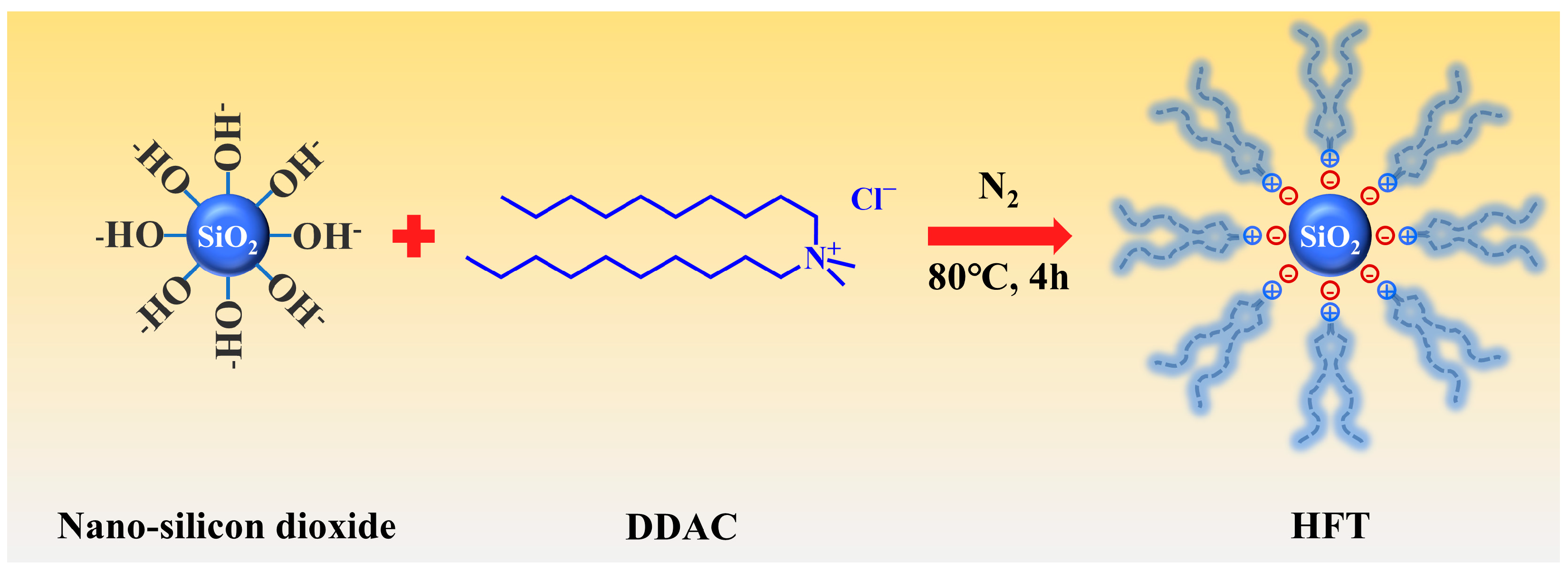
2.2. Preparation Method

The preparation method is shown in Figure 1, a total of 6 g of hydrophilic spherical nano-silica were dispersed in 150 mL deionized water by high-speed stirring for 10 min, followed by ultrasonication for 20 min, to obtain a homogeneous suspension. The dispersion was then transferred to a three-neck flask and heated in a water bath at 80 °C. Under vigorous stirring and a nitrogen atmosphere, 9 g of DDAC was added dropwise at a constant rate, and the reaction was allowed to proceed for 4 h. The resulting product was collected by centrifugation, dried, and milled to afford a white powder [33,40].

2.3. Characterization Method

The chemical structure of HFT was analyzed with a Shimadzu IRTracer-100 FT-IR spectrometer (Shimadzu Corporation, Kyoto, Japan) using KBr pellets (400–4000 cm−1, 4 cm−1 resolution). Thermal stability and composition were evaluated by thermogravimetric analysis on a Mettler Toledo TGA/DSC 3+ (Mettler-Toledo AG, Greifensee, Switzerland) under nitrogen (10 °C min−1, 20–800 °C). Zeta potential and particle-size distribution were measured at 25 °C with a Malvern Zetasizer Nano ZS (Malvern Panalytical Ltd., Worcestershire, UK). Microstructural characteristics were observed with a Guanyi Quantum SEM5000X scanning electron microscope (CIQTEK Co., Ltd., Hefei, China) and a JEOL JEM-F200 transmission electron microscope (JEOL Ltd., Tokyo, Japan).

2.4. Evaluation of the Influence on the Rheological and Filtration Properties of Bentonite Slurry

The rheological behavior and filtrate loss of bentonite slurry are critical for cuttings transport, pumping efficiency, and wellbore stability in deepwater drilling operations. This study evaluates the influence of HFT on the rheological and filtration properties of bentonite slurry in compliance with API standards.
Rheological measurements were performed with a six-speed rotational viscometer. Before testing, samples were equilibrated in a thermostatic water bath and examined at 25 °C (surface) and 4 °C (typical deepwater mudline temperature). Dial readings at 600 and 300 r min−1600 and θ300, respectively) were recorded, and the apparent viscosity (AV, mPa·s), plastic viscosity (PV, mPa·s), and yield point (YP, Pa) were calculated according to Equations (1)–(3):
A V = θ 600 / 2
P V = θ 600 θ 300
Y P = θ 300 P V / 2
Filtration loss (FL) of the drilling fluid was measured with a medium-pressure filter press by API standard procedures and reported in milliliters (mL).

2.5. Evaluation of Blocking Performance

The nanopore-plugging performance of HFT was evaluated with polytetrafluoroethylene (PTFE) microfiltration membranes possessing nominal pore diameters of 100, 200, and 450 nm. Membrane coupons collected before and after the tests were dried and examined for microstructural changes by scanning electron microscopy (Guanyi Quantum SEM5000X, CIQTEK Co., Ltd., No. 1969 Kongquetai Road, High-tech Zone, Hefei, China). Filtration-loss tests were carried out on an SD6A API filter press (Qingdao, China) using a 1 wt% aqueous HFT solution at 0.7 MPa and room temperature for 7.5 min. The filtrate volume obtained for each membrane was recorded to quantify the nanopore-plugging efficiency of HFT.

2.6. Evaluation of Hydration Inhibition Performance

Core immersion tests were conducted at room temperature to visually assess HFT’s inhibition of shale hydration. Artificial cores (2.5 cm diameter, ≈1 cm height) were fabricated by pressing 10 g of bentonite in a hydraulic cylindrical mold at 10 MPa for 5 min. Four test fluids—1 wt% HFT, 5 wt% KCl, 1 wt% UHIB, and deionized water (control)—were prepared. Each core was fully immersed in its designated fluid, and photographs were taken at predetermined intervals to monitor morphological changes and compare stability among the fluids.
Linear expansion tests were performed with a CPZ-2 dual-channel dilatometer (Qingdao Tongchun, Qingdao, China) to quantify HFT’s inhibition of shale hydration swelling. Artificial cores were placed in the test cylinders and exposed to equal volumes of 1 wt% HFT, 5 wt% KCl, 1 wt% UHIB, or deionized water (control). The axial expansion was recorded continuously over 24 h, and the final linear expansion ratio was calculated to compare each fluid’s efficacy in suppressing bentonite swelling.
Rolling recovery tests were conducted to quantify HFT’s efficacy in inhibiting shale hydration dispersion. Twenty grams of 6–10 mesh shale cuttings were tested in four media: 1 wt% HFT, 5 wt% KCl, 1 wt% UHIB, and deionized water (control). A 350 mL aliquot of each dispersion was placed in an aging cell, the cuttings were added, and the mixtures were rolled at 120 °C for 16 h. After aging, the cuttings were collected, sieved through a 40-mesh screen, and oven dried to constant weight. Rolling recovery was calculated by comparing the final dry mass with the initial mass, thus evaluating each medium’s capacity to suppress shale dispersion.

2.7. Evaluation of Hydrophobic Performance

Surface tension was determined with a Dataphysics automated tensiometer (DCAT21) (DataPhysics Instruments GmbH, Filderstadt, Germany) employing the ring method. Deionized water (control) and 1 wt% HFT solutions were prepared and equilibrated at 25 °C for 30 min. The instrument automatically recorded the detachment force of the ring from the liquid surface, from which surface tension values were calculated.
The wetting properties of hydrophilic shale in various solutions were assessed by the sessile drop method using a DataPhysics OCA-25 optical contact-angle goniometer (DataPhysics Instruments GmbH, Filderstadt, Germany). Shale disks (2.5 cm diameter) were placed in a 350 mL aging vessel and aged at 120 °C for 16 h in a rotary oven. After cooling to ambient temperature and drying, the static water contact angle of each disk was recorded with the OCA-25. Scanning electron microscopy (SEM) and atomic force microscopy (AFM) images of the cores before and after treatment were acquired using a ZEISS GeminiSEM 360 (Carl Zeiss Microscopy GmbH, Jena, Germany) and an Oxford Instruments MFP-3D Origin+ system (Abingdon, UK), respectively.
Capillary rise experiments using 1 mm–ID glass tubes were conducted to examine water capillarity in shale after HFT adsorption. Tubes were rinsed with deionized water, purged with high-pressure nitrogen, and oven dried. The dried tubes were then immersed in deionized water or 1 wt% HFT solution and aged at 120 °C for 16 h. After aging, the tubes were purged and dried again to remove residual liquid. Each tube was vertically inserted into a methylene blue-stained water bath, where capillary forces drove the fluid upward along the tube wall to equilibrium. Rise height was recorded upon removal.

3. Result and Discussion

3.1. Characterization of HFT

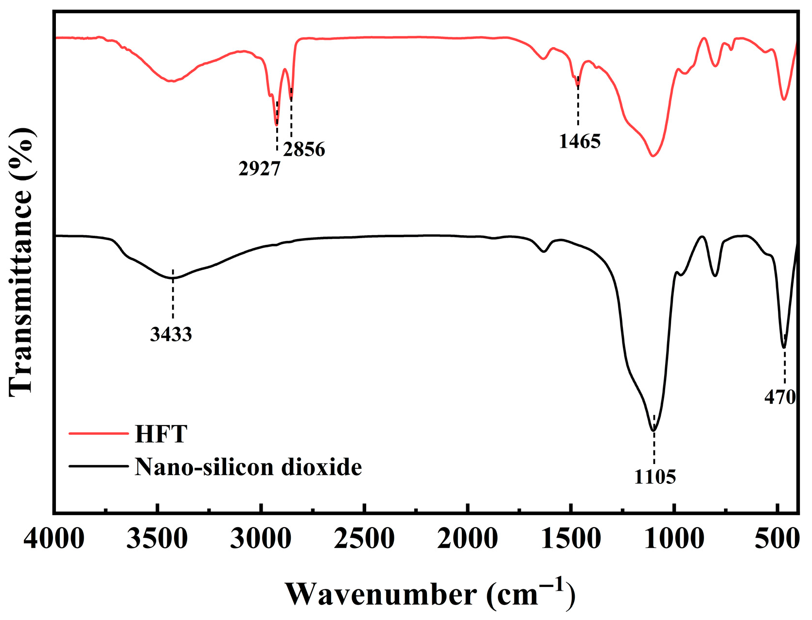
3.1.1. FT-IR Analysis

Figure 2 presents the FT-IR spectra of nano-silica before and after modification. The unmodified nano-silica exhibits a broad hydroxyl (–OH) stretching band at 3433 cm−1 and characteristic Si–O–Si asymmetric stretching and bending bands at 1105 and 470 cm−1, respectively. After modification, the HFT spectrum retains the Si–O–Si peaks at 1105 and 470 cm−1, whereas the –OH band at 3433 cm−1 is significantly attenuated, suggesting partial shielding or replacement of surface silanol groups by the quaternary ammonium salt. New –CH2– asymmetric and symmetric stretching bands emerge at 2927 and 2856 cm−1, respectively, accompanied by a –CH2– bending band at 1465 cm−1, all arising from DDAC’s long alkyl chains. These changes confirm the electrostatic adsorption of didodecyl dimethyl ammonium cations onto the silica’s silanol sites, forming a hydrophobic organic shell and yielding the target product HFT.

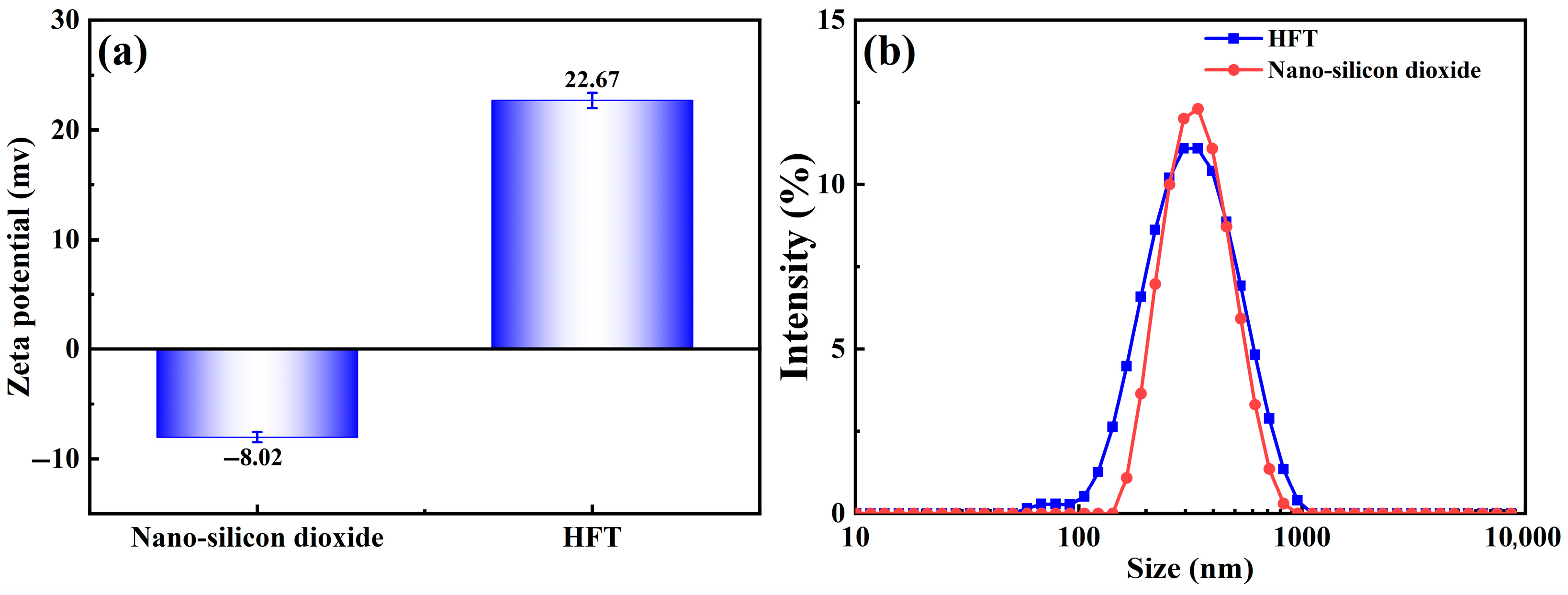
3.1.2. Zeta Potential and Particle Size Analysis
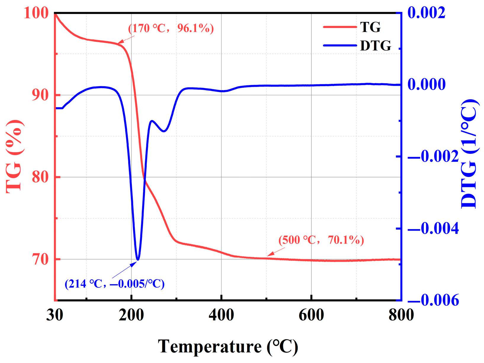
Zeta potential and particle size distribution were measured with a Malvern Zetasizer Nano ZS, and the results are presented in Figure 3. In Figure 3a, unmodified nano-silica dispersed in water exhibits a negative surface charge, with an average zeta potential of −8.02 mV (absolute value less than 15 mV), indicating electrostatic instability. After modification, HFT’s zeta potential shifts to +22.67 mV, confirming that quaternary ammonium cations have coated the SiO2 surface, thereby enhancing electrostatic repulsion and stabilizing particle dispersion [33,40]. The strong positive charge further promotes HFT adsorption onto negatively charged shale and clay surfaces, improving its inhibition performance.
Figure 3b shows the particle size distributions. The unmodified sample displays a volume median diameter of approximately 342 nm in water, with a size range of 142 to 955 nm. Post-modification, the median particle diameter decreased to approximately 295 nm, with the size distribution widening to a range of 58.8–1110 nm. The reduced particle size indicates enhanced dispersibility due to surface modification, while the widened distribution (tens to over a thousand nanometers) facilitates multiscale pore throat plugging and improves nanoscale collapse prevention. These findings confirm successful DDAC modification and demonstrate that HFT possesses excellent dispersion stability and pore-blocking efficacy.

3.1.3. TGA Analysis

Figure 4 displays the TG and DTG curves of HFT. From 30 to 170 °C, the sample loses only 3.9 wt%, corresponding to desorption of physically adsorbed water and light volatiles, and indicating negligible thermal degradation below 160 °C under typical deepwater conditions. As the temperature rises from 170 to 214 °C, the DTG trace shows a pronounced negative peak (−0.005 wt%/°C), and the TG curve undergoes a sharp mass loss, completing near 214 °C, which marks the decomposition of DDAC alkyl chains on the SiO2 surface. Beyond this range, the TG curve levels off, stabilizing at approximately 70.1 wt% by 500 °C, confirming that the remaining mass is the thermally robust silica framework. Overall, HFT exhibits outstanding thermal stability up to 160 °C—satisfying the broad-temperature requirements of deepwater drilling—and the distinct mass-loss event between 170 and 214 °C verifies successful DDAC loading onto nano-SiO2.

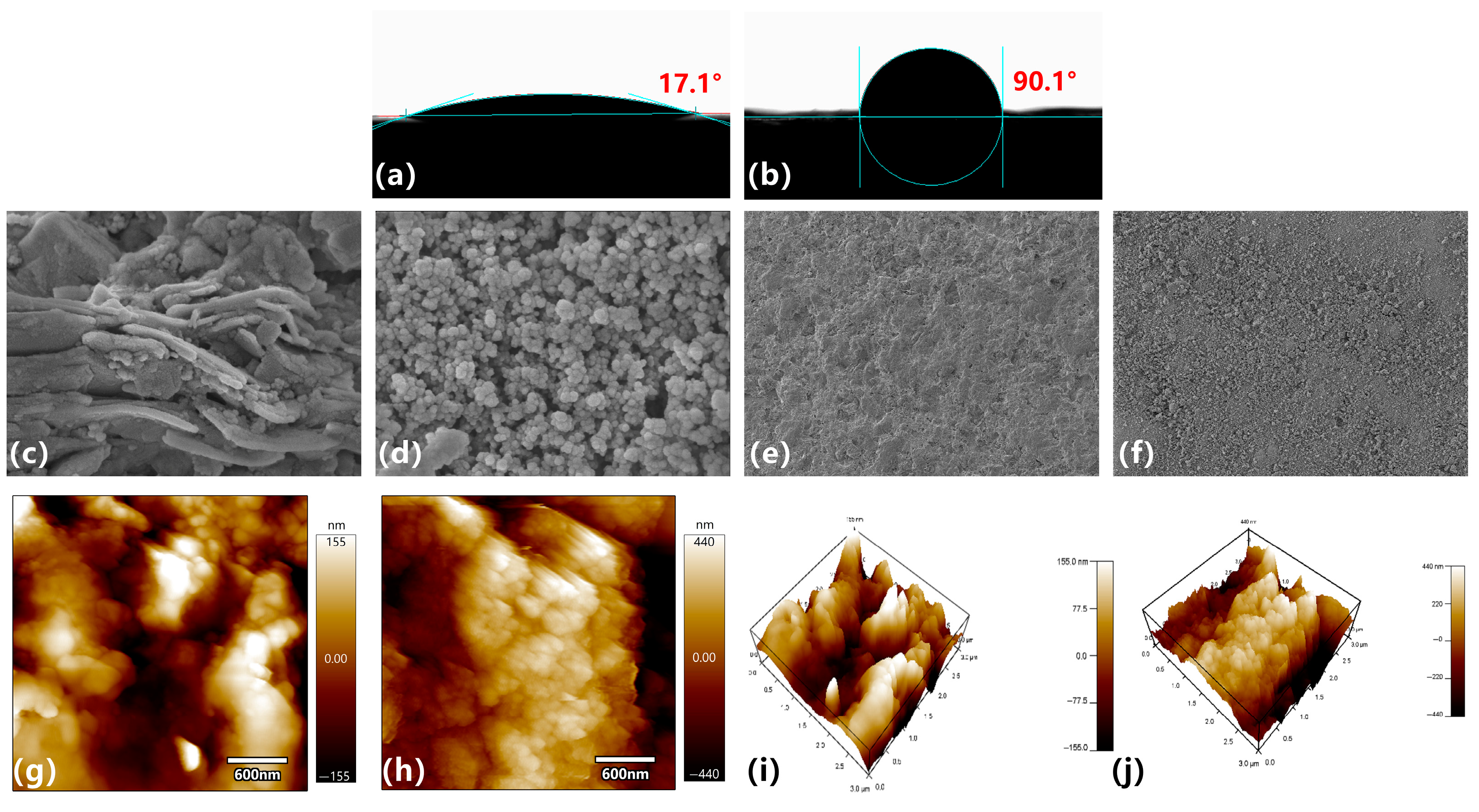
3.1.4. Microscopic Morphology Analysis

Figure 5 depicts the microstructure of HFT. The SEM image (Figure 5a) shows nearly spherical particles forming a loosely clustered network via point contacts, with pronounced interparticle porosity and a uniform spatial distribution. The TEM micrograph (Figure 5b) reveals a thin, lower-contrast organic layer surrounding each nanoparticle, corresponding to the DDAC coating. These observations confirm that the modification preserved the original particle size while generating a uniform organic shell, providing the morphological foundation for subsequent collapse-resistance testing.

3.2. Evaluation of the Effect of HFT on the Rheological Filtration Loss of Bentonite Slurry

Near the seabed mudline, deepwater drilling fluids typically operate at 2–6 °C; accordingly, 4 °C was selected as the representative temperature in this study. Because additive-induced viscosity increases can raise pump pressure, lower hydraulic efficiency, and reduce bit rotation, evaluating the influence of HFT on the low-temperature rheological and filtration properties of bentonite slurries is essential.
As shown in Figure 6, a 4 wt% bentonite slurry exhibits an apparent viscosity (AV) of 7 mPa·s, a plastic viscosity (PV) of 5 mPa·s, and a yield point (YP) of 2 Pa at 25 °C; under low-temperature conditions (4 °C), these values increase to 10 mPa·s, 7 mPa·s, and 3 Pa, respectively. Introducing 1 wt% HFT produces only minor changes: at 25 °C, the AV, PV, and YP shift to 9 mPa·s, 6 mPa·s, and 3 Pa, whereas at 4 °C they reach 12.5 mPa·s, 10 mPa·s, and 2.5 Pa. All parameters remain well below the limits commonly specified for deepwater operations (AV ≤ 20 mPa·s; PV ≤ 15 mPa·s), confirming that HFT preserves acceptable rheology at both ambient and low temperatures without compromising pumpability.
Regarding filtration loss, the API filtration loss volume increases modestly from 16 to 22 mL after HFT addition. It is important to note that HFT is designed to seal formation pores on the order of tens to hundreds of nanometers, whereas API filter paper has a pore size of approximately 10 µm, limiting effective plugging. Furthermore, HFT’s positive charge inhibits bentonite hydration and dispersion, promoting clay flocculation and particle growth, which slightly increases filter-cake permeability and thus filtration loss; however, this increase remains acceptable in field operations.

3.3. Evaluation of the Blocking Performance of HFT

Figure 7 visually demonstrates the nanoscale plugging efficacy of 1 wt% HFT. In the absence of HFT, PTFE membranes with pore diameters of 100, 200, and 450 nm exhibit almost complete filtrate loss within seconds, indicating negligible resistance to flow. Following HFT addition, filtrate volumes decrease significantly, with the 200 nm membrane showing optimal performance (55 mL loss) compared to the 100 nm (74 mL) and 450 nm (72 mL) membranes. This behavior corresponds to the HFT particle-size distribution (58.8–1100 nm), as pore sizes near the median particle diameter (~300 nm) maximize particle bridging and particle–pore-wall interactions. Meanwhile, the surface of the particles is strongly positively charged, which enhances their dispersion stability and is more conducive to sealing the nanopores under different pore sizes.
SEM images further elucidate the plugging mechanism. At a 20 μm field of view (Figure 7b,c), the untreated membrane displays an open fibrous network with exposed pore throats, whereas after treatment, the fibers are uniformly coated with HFT particles, markedly reducing pore connectivity. At a 1 μm field of view (Figure 7d,e), HFT nanoparticles deposit along the pore walls and self-assemble into multilayered, flocculent shells, converting through-pores into semi-closed structures and establishing a graded plugging profile from the membrane surface inward.

3.4. Evaluation of the Hydration Inhibition Performance of HFT

3.4.1. Core Immersion Tests

Figure 8 intuitively illustrates the appearance of artificial cores after immersion in various solutions. In deionized water, cores become turbid within 12 h and ultimately collapse, indicating severe bentonite hydration, swelling, and dispersion. In the 5 wt% KCl system, large fragments spall at 12 h, and by 24 h, the core has expanded further and exhibits extensive cracking, showing that ionic suppression alone cannot preserve structural integrity. In the 1 wt% UHIB system, network-like cracks emerge at 12 h and develop into deep fissures with significant spalling by 24 h. By contrast, cores treated with 1 wt% HFT display only fine shrinkage cracks at 12 h and limited block spalling at 24 h, demonstrating HFT’s superior inhibition of bentonite hydration, swelling, and dispersion.

3.4.2. Linear Expansion Tests

Linear expansion tests quantify each system’s ability to inhibit bentonite hydration swelling (Figure 9). The deionized water control shows the greatest expansion, with a 24 h linear expansion rate of 67.23%. In the 5 wt% KCl system, expansion is slightly lower than water during the first three hours, then surpasses and plateaus at 46.04% after about 7.5 h. The 1 wt% UHIB system exhibits a smoother expansion profile, reaching 40.99% at 24 h. The 1 wt% HFT system maintains the lowest expansion throughout, with a 24 h rate of 36.93%—a 30.3% reduction relative to deionized water, demonstrating superior swelling inhibition.

3.4.3. Rolling Recovery Tests

Rolling recovery tests quantitatively assess an inhibitor’s capacity to inhibit shale-cutting hydration and dispersion. As shown in Figure 10, 16 h recovery rates vary markedly. Deionized water yields only 15.1%, with cuttings nearly fully disintegrated. Using 5 wt% KCl increases recovery to 19.7%. Incorporating 1 wt% UHIB raises recovery to 66.85%, demonstrating strong inhibition of hydration and dispersion. The 1 wt% HFT system achieves the highest recovery at 68.65%, more than triple that of deionized water and marginally superior to UHIB. These results confirm that HFT effectively inhibits shale hydration and dispersion, thereby enhancing wellbore stability.

3.5. Evaluation of the Hydrophobic Properties of HFT

3.5.1. Surface Tension Tests

Figure 11 presents a comparison of surface tension between a 1 wt% HFT solution and deionized water. Pure water has a surface tension of 71.14 mN/m, which decreases to 40.55 mN/m upon the addition of HFT—a reduction of 43%. This substantial decrease stems from the oriented alignment of HFT’s double hydrophobic-chain quaternary ammonium ions at the gas–liquid interface, boosting surface activity. Lower surface tension reduces capillary suction at the wellbore, limits filtrate penetration into shale micropores, and thus helps suppress shale hydration and improve wellbore stability.

3.5.2. Wettability Tests

Figure 12 shows changes in wettability and surface microtopography of shale disks before and after HFT treatment. In Figure 12a, untreated shale has a contact angle of only 17.1°, indicating strong hydrophilicity. After HFT treatment (Figure 12b), the contact angle rises to 90.1°, demonstrating that HFT adsorbs onto the mineral surface to form a hydrophobic coating, thereby significantly reducing water-wetting tendency.
At the nanoscale (200 nm), SEM images (Figure 12c,d) reveal that the original shale surface exhibits layered exfoliation with visible pores. After HFT treatment, a particulate coating fills these regions and partially seals the pores. At the microscale (20 μm), SEM images (Figure 12e,f) show that most microcracks and micropores are similarly covered, resulting in a denser surface. AFM height maps further quantify roughness changes: before treatment (Figure 12g,i), the surface displays pronounced peaks and valleys; after treatment (Figure 12h,j), peak-to-valley variations decrease and overall smoothness improves, owing to HFT adsorption and pore blocking.

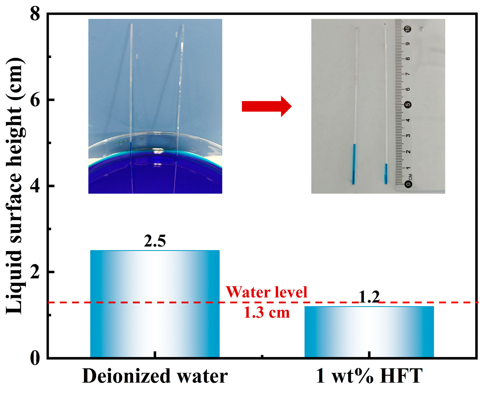
3.5.3. Capillary Rise Height Tests

Capillary rise tests visually replicate water infiltration into shale micropores and microfractures under capillary forces. In deionized water (Figure 13), the liquid column rises to 2.5 cm—well above the 1.3 cm reference waterline (red dashed line)—demonstrating continuous hydrophilic capillary suction into shale pores. By contrast, after treatment with 1 wt% HFT, the column height reaches only 1.2 cm, below the reference, indicating a reversal of capillary action from suction to repulsion and a reduction of approximately 52%. This finding shows that HFT markedly suppresses capillary suction in shale pore throats, thereby mitigating hydration-induced expansion from filtrate invasion and further enhancing wellbore stability.

3.6. Study of the Collapse Prevention Mechanism of HFT

Figure 14 illustrates the multifunctional, synergistic mechanisms by which HFT prevents collapse in deepwater wellbores. Initially, HFT particles bridge and stack within shale micro- and nanopores, interfiling with smaller particles to form a dense nanoscale plugging layer that occludes pore throats. This layer effectively blocks water invasion and reduces shale hydration. Simultaneously, quaternary ammonium ions on the HFT surface electrostatically adsorb to negatively charged pore walls, firmly anchoring the plugging layer and preventing detachment. Exposed alkyl chains form a continuous hydrophobic film on the shale surface, converting it from hydrophilic to hydrophobic. Consequently, capillary forces shift from water attraction to repulsion, further inhibiting fluid entry. By coupling plugging, adsorption, and wettability reversal, HFT blocks pathways for hydration-induced swelling and dispersion, thereby ensuring wellbore stability during deepwater drilling.

4. Conclusions

In summary, we functionalized nano-silica with a long-chain hydrophobic cationic surfactant to develop a hydrophobically modified nanoscale collapse-prevention agent (HFT). Performance tests and mechanistic studies demonstrate that HFT stabilizes wellbores through synergistic nanoscale pore plugging, electrostatic adsorption, and wettability reversal, highlighting its strong potential for deepwater drilling applications. The main conclusions are as follows:
  • HFT was successfully fabricated and characterized by FT-IR, zeta potential, particle-size distribution, TGA, SEM, and TEM. These analyses confirm the presence of a hydrophobic organic shell on the HFT surface, as well as its positive surface charge, good dispersibility, and high thermal stability.
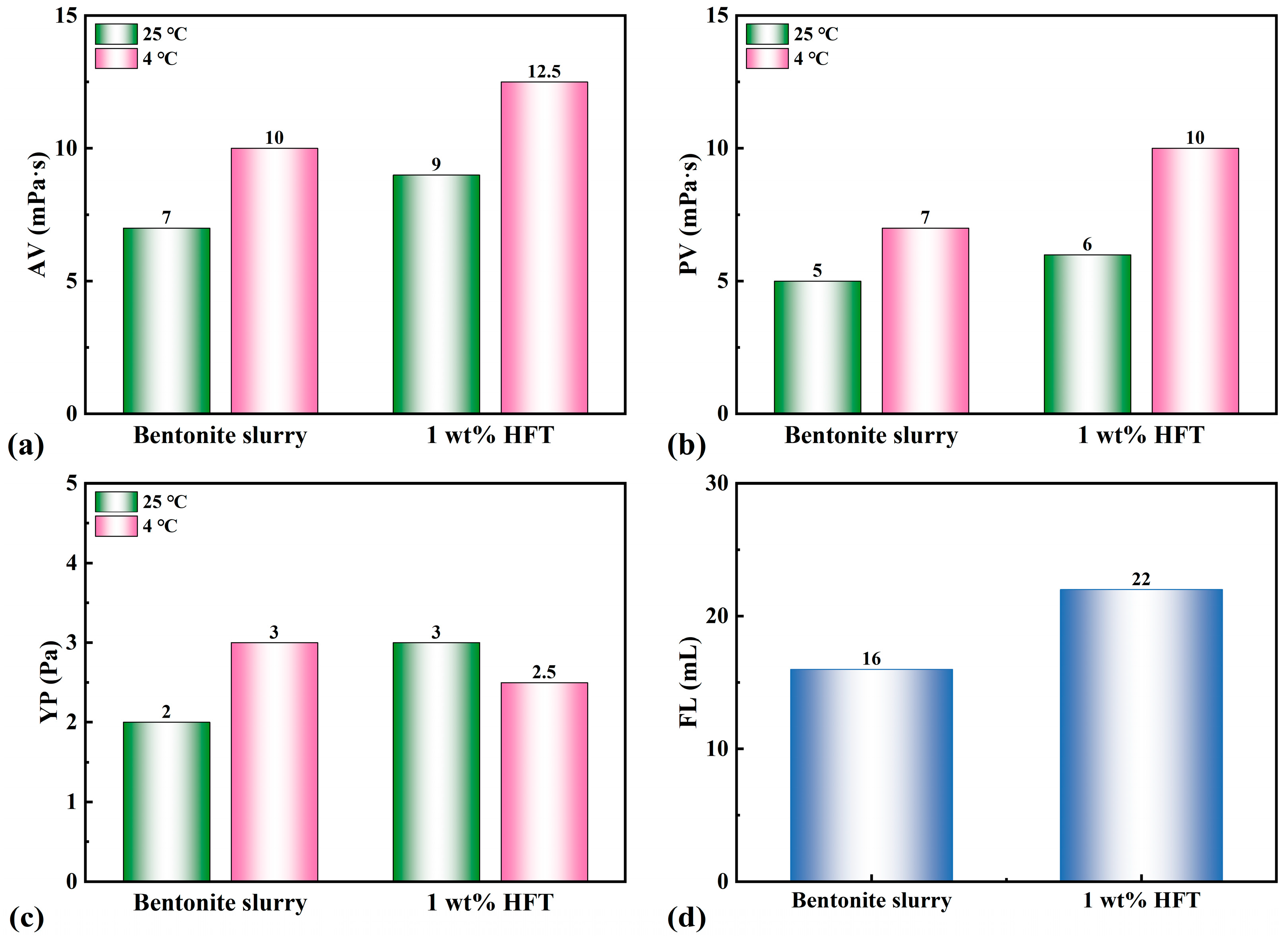
  • The incorporation of 1 wt% HFT produced only minor changes in the properties of the bentonite slurry. At 25 °C, the apparent viscosity rose slightly from 7 to 9 mPa·s, the plastic viscosity from 5 to 6 mPa·s, the yield point remained essentially unchanged at 3 Pa, and the API filtration loss increased modestly from 16 to 22 mL. Even at 4 °C, the slurry retained acceptable rheology (AV = 12.5 mPa·s, PV = 10 mPa·s, YP = 2.5 Pa), well within the limits commonly specified for deepwater operations. Consequently, HFT does not hinder—indeed, it preserves—the pumpability of the bentonite slurry under shallow, low-temperature, deepwater conditions.
  • HFT demonstrates exceptional nanoscale pore-plugging performance. The filtrate volume across membranes with pore sizes of 100 nm, 200 nm, and 450 nm decreased to 74, 55, and 72 mL, respectively, with the greatest reduction observed for the 200 nm membrane. Scanning electron microscopy confirmed that HFT nanoparticles assembled into a continuous sealing layer within the pore network, significantly hindering filtrate penetration.
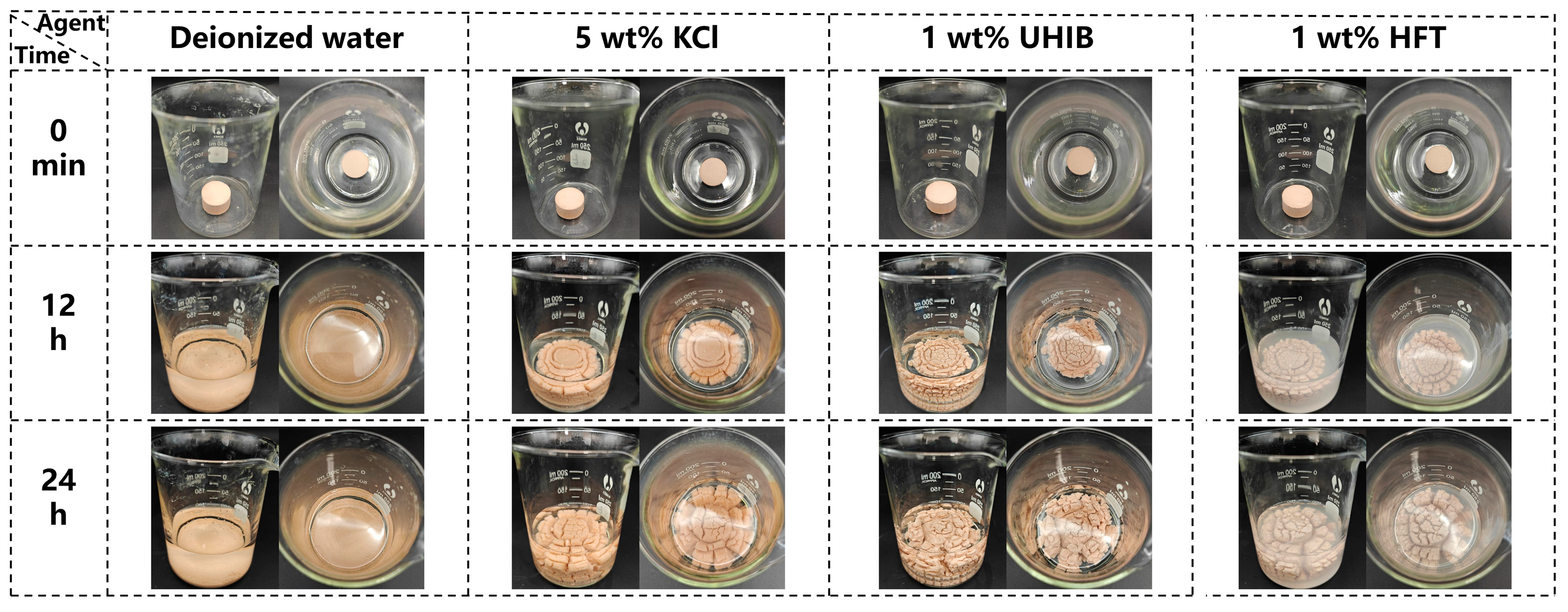
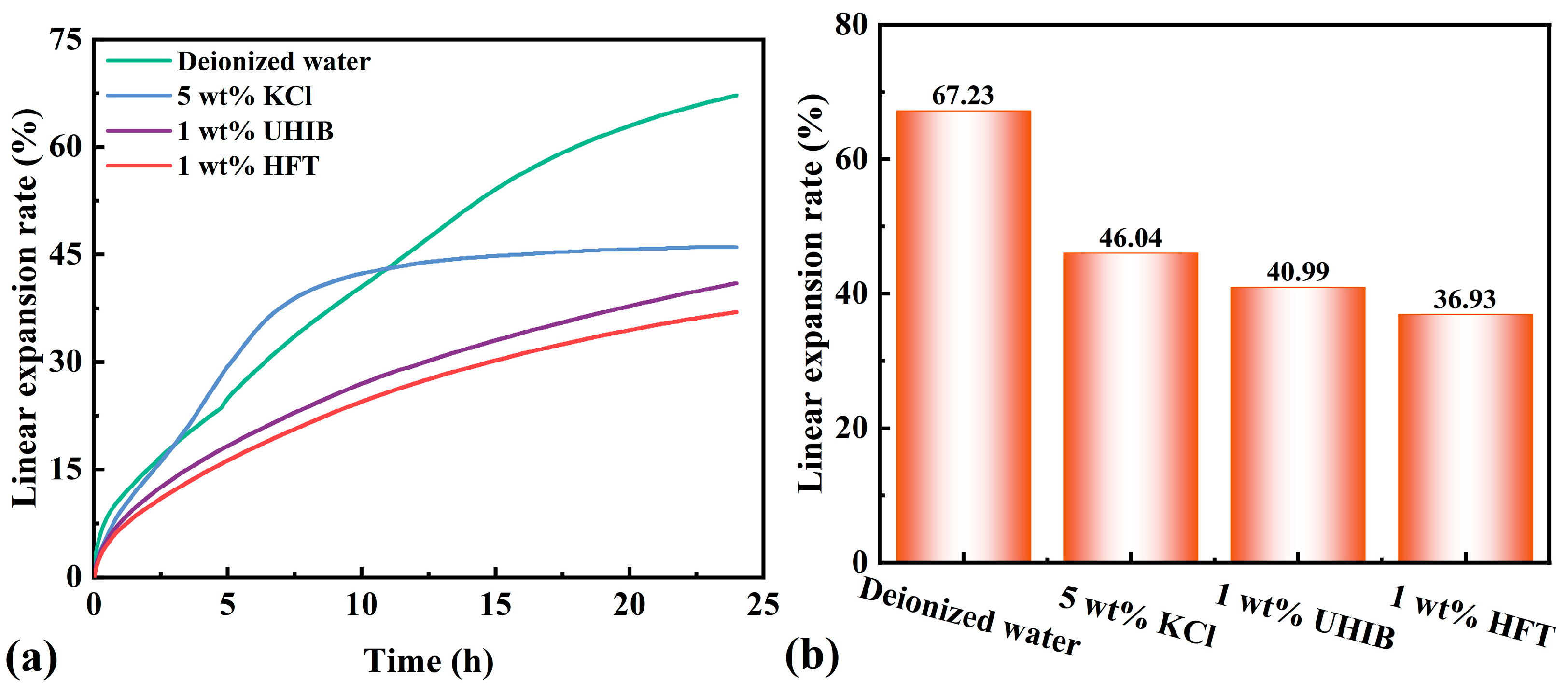
  • Core-immersion tests indicated that shale cores soaked for 24 h in 1 wt% HFT retained overall integrity, displaying only minor shrinkage cracks and limited spalling, whereas cores immersed in de-ionized water or alternative inhibitors suffered severe spalling and collapse. Linear-expansion measurements further showed that HFT lowered the 24 h swelling ratio from 67.23% (deionized water) to 36.93%, a reduction of approximately 45%. Rolling recovery experiments revealed that 1 wt% HFT increased shale-cuttings recovery to 68.65%, outperforming both 5 wt% KCl (19.7%) and a commercial polyamine inhibitor (66.85%). Collectively, these findings demonstrate that HFT efficiently suppresses the hydration, swelling, and dispersion of clay minerals.
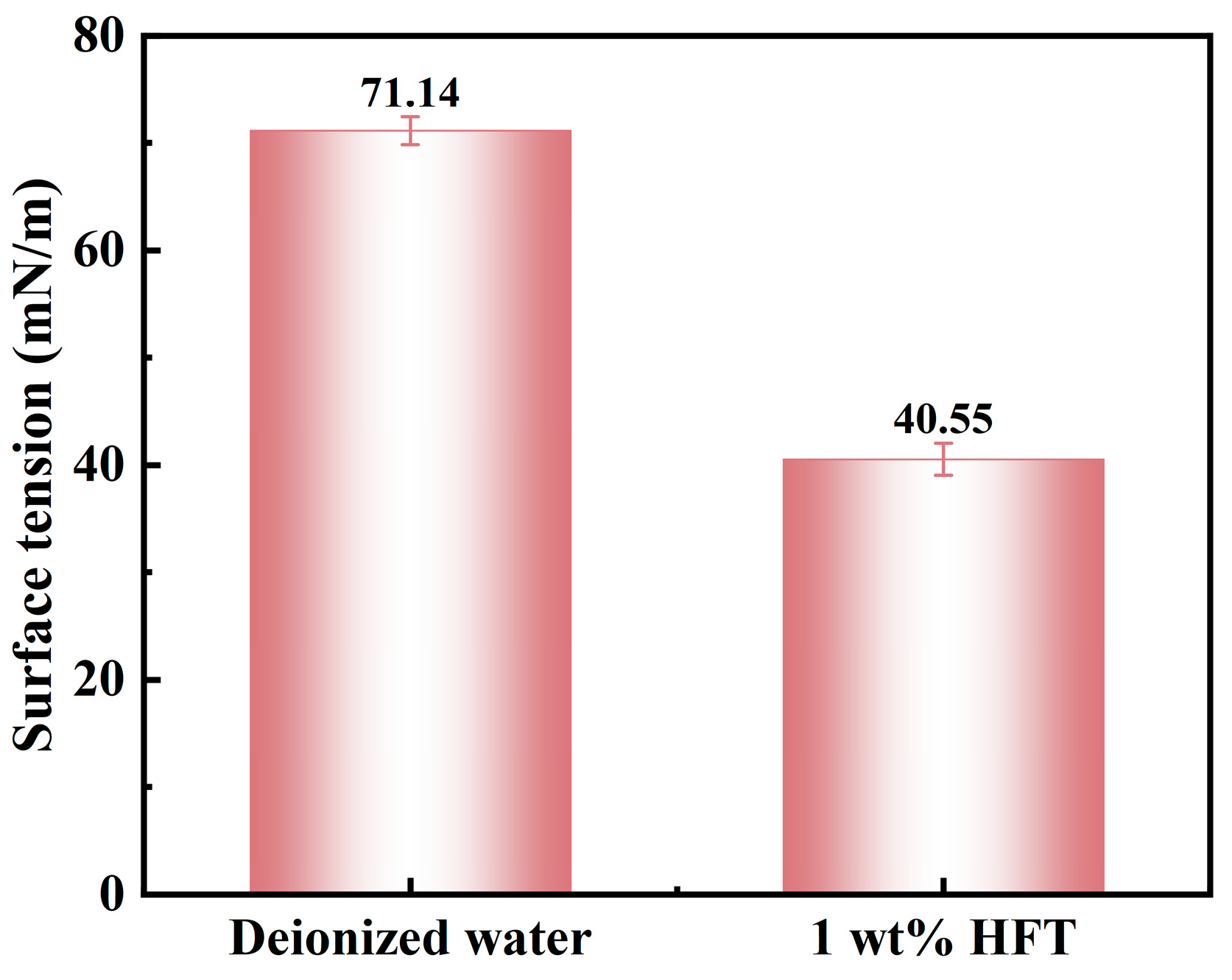
  • Wettability tests indicated that treating shale with HFT increased the static water contact angle from 17.1° to 90.1°, signifying a transition from hydrophilicity to pronounced hydrophobicity. Surface-tension measurements further showed that a 1 wt% HFT solution reduced the surface tension of water from 71.14 mN m−1 to 40.55 mN m−1, a decrease of roughly 43%. In capillary rise experiments, the equilibrium height fell from 2.5 cm in untreated capillaries to 1.2 cm after HFT application—52% reduction—and the capillary pressure reversed from suction to repulsion. Collectively, these observations demonstrate that HFT forms a continuous hydrophobic film on shale surfaces, markedly modifying wettability and capillary forces and thereby inhibiting hydration.

Author Contributions

Conceptualization, writing—review and editing, supervision, project administration, and funding acquisition: J.W.; methodology and investigation: H.L.; software: H.X.; validation: J.G.; formal analysis, data curation, and writing—original draft preparation: Z.H.; resources and visualization: S.S. All authors have read and agreed to the published version of the manuscript.

Funding

This research was supported by the National Key Research and Development Program of China (2021YFC2800803), the National Natural Science Foundation of China (No. 52274025 and U2444216), the Independent Innovation Research Program of China University of Petroleum (East China) (27RA2502006), Funding for Research Initiation and Activities of Academicians in Shandong (ZX20190005), and the Taishan Scholar Plan Project of Shandong Province (TSQN202408090).

Data Availability Statement

Data will be made available upon request.

Conflicts of Interest

Author Haiwei Li was employed by the Jiangsu Gas Storage Sub-Company, PipeChina West East Gas Pipeline Company. Author Jian Guan, Hao Xu was employed by the Qingdao NMEI Group Co., Ltd. The remaining authors declare that the research was conducted in the absence of any commercial or financial relationships that could be construed as a potential conflict of interest.

References

  1. Aklin, M.; Urpelainen, J. Renewables: The Politics of a Global Energy Transition; MIT Press: Cambridge, MA, USA, 2018; ISBN 0-262-53494-0. [Google Scholar]
  2. He, Z.; Wang, J.; Liao, B.; Bai, Y.; Shao, Z.; Huang, X.; Wang, Q.; Li, Y. Molecular Simulation of Interactions between High-Molecular-Polymer Flocculation Gel for Oil-Based Drilling Fluid and Clay Minerals. Gels 2022, 8, 442. [Google Scholar] [CrossRef] [PubMed]
  3. Sun, J.; Li, Y.; Liao, B.; Bai, Y.; Li, W.; Xu, J.; Wang, J. Development and Performance Evaluation of Bioenzyme-Responsive Temporary Plugging Materials. Adv. Geo-Energy Res. 2024, 11, 20–28. [Google Scholar] [CrossRef]
  4. Zou, C.; Zhai, G.; Zhang, G.; Wang, H.; Zhang, G.; Li, J.; Wang, Z.; Wen, Z.; Ma, F.; Liang, Y.; et al. Formation, Distribution, Potential and Prediction of Global Conventional and Unconventional Hydrocarbon Resources. Pet. Explor. Dev. 2015, 42, 14–28. [Google Scholar] [CrossRef]
  5. Guo, X.; Hu, D.; Li, Y.; Duan, J.; Zhang, X.; Fan, X.; Duan, H.; Li, W. Theoretical Progress and Key Technologies of Onshore Ultra-Deep Oil/Gas Exploration. Engineering 2019, 5, 458–470. [Google Scholar] [CrossRef]
  6. Xu, C.; Zou, W.; Yang, Y.; Duan, Y.; Shen, Y.; Luo, B.; Ni, C.; Fu, X.; Zhang, J. Status and Prospects of Deep Oil and Gas Resources Exploration and Development Onshore China. J. Nat. Gas Geosci. 2018, 3, 11–24. [Google Scholar] [CrossRef]
  7. Mu, L.; Ji, Z. Technologcial Progress and Development Directions of PetroChina Overseas Oil and Gas Exploration. Pet. Explor. Dev. 2019, 46, 1088–1099. [Google Scholar] [CrossRef]
  8. Wang, J.; He, Z.; Yichen, Y.; Lei, L.; Jin, Y.; Liao, B.; Zhao, K.; Li, Y.; Chen, L. Development of a Dual-Functional Inhibitor for Natural Gas Hydrates and Construction of Drilling Fluid System. Gas Sci. Eng. 2024, 122, 205218. [Google Scholar] [CrossRef]
  9. Wen, Z.; Wang, J.; Wang, Z.; He, Z.; Song, C.; Liu, X.; Zhang, N.; Ji, T. Analysis of the World Deepwater Oil and Gas Exploration Situation. Pet. Explor. Dev. 2023, 50, 1060–1076. [Google Scholar] [CrossRef]
  10. Wang, J.; Liao, B.; Liu, L.; Chen, L.; Huang, Y.; Zhao, K.; Sun, X.; Lv, K.; Zheng, Y.; Sun, J. The Effect of Multi-Component Inhibitor Systems on Hydrate Formation. Gas Sci. Eng. 2024, 122, 205214. [Google Scholar] [CrossRef]
  11. Wang, J.; Liu, L.; Zhang, S.; Liao, B.; Zhao, K.; Li, Y.; Xu, J.; Chen, L. Review of the Perspectives and Study of Thermo-Responsive Polymer Gels and Applications in Oil-Based Drilling Fluids. Gels 2023, 9, 969. [Google Scholar] [CrossRef] [PubMed]
  12. Zou, C.; Zhang, G.; Tao, S.; Hu, S.; Li, X.; Li, J.; Dong, D.; Zhu, R.; Yuan, X.; Hou, L.; et al. Geological Features, Major Discoveries and Unconventional Petroleum Geology in the Global Petroleum Exploration. Pet. Explor. Dev. 2010, 37, 129–145. [Google Scholar] [CrossRef]
  13. Dou, L.; Wen, Z.; Wang, J.; Wang, Z.; He, Z.; Liu, X.; Zhang, N. Analysis of the World Oil and Gas Exploration Situation in 2021. Pet. Explor. Dev. 2022, 49, 1195–1209. [Google Scholar] [CrossRef]
  14. Rajput, S.; Thakur, N.K.; Thakur, N.K.; Rajput, S. World’s Oil and Natural Gas Scenario. In Exploration of Gas Hydrates: Geophysical Techniques; Springer: Berlin/Heidelberg, Germany, 2011; pp. 29–47. [Google Scholar]
  15. Pettingill, H.S.; Weimer, P. World-Wide Deep Water Exploration and Production: Past, Present and Future; GeoScienceWorld: McLean, VA, USA, 2002. [Google Scholar]
  16. Lei, Q.; Xu, Y.; Yang, Z.; Cai, B.; Wang, X.; Zhou, L.; Liu, H.; Xu, M.; Wang, L.; Li, S. Progress and Development Directions of Stimulation Techniques for Ultra-Deep Oil and Gas Reservoirs. Pet. Explor. Dev. 2021, 48, 221–231. [Google Scholar] [CrossRef]
  17. Ahlbrandt, T.S. Future Petroleum Energy Resources of the World. Int. Geol. Rev. 2002, 44, 1092–1104. [Google Scholar] [CrossRef]
  18. Haider, W.H. Estimates of Total Oil & Gas Reserves in the World, Future of Oil and Gas Companies and Smart Investments by E & P Companies in Renewable Energy Sources for Future Energy Needs. In Proceedings of the International Petroleum Technology Conference IPTC, Dhahran, Saudi Arabia, 13–15 January 2020; p. D011S009R002. [Google Scholar]
  19. Wang, Z.; Sun, J.; Lv, K.; Lu, H.; Geng, Y.; Huang, X. Thermosensitive Core-Shell Polymer Microspheres for Enhanced Wellbore Stability in Deep-Water Water-Based Drilling Fluids. J. Mol. Liq. 2025, 418, 126690. [Google Scholar] [CrossRef]
  20. Kjärstad, J.; Johnsson, F. Resources and Future Supply of Oil. Energy Policy 2009, 37, 441–464. [Google Scholar] [CrossRef]
  21. Chakhmakhchev, A.; Rushworth, P. Global Overview of Recent Exploration Investment in Deepwater-New Discoveries, Plays and Exploration Potential. In Proceedings of the Adapted from oral presentation at AAPG Convention, New Orleans, LA, USA, 11–14 April 2010. [Google Scholar]
  22. Weimer, P.; Pettingill, H.S. Deep-Water Exploration and Production: A Global Overview; AAPG: Tulsa, OK, USA, 2007. [Google Scholar]
  23. Lekamge, S.A.; Mahawaththa, I.; Weerasinghe, S. Offshore Oil and Gas Operations: Environmental Impacts and Mitigation Methods. In Coastal and Marine Pollution: Source to Sink, Mitigation and Management; John Wiley & Sons Ltd.: Hoboken, NJ, USA, 2025; pp. 67–87. [Google Scholar]
  24. Qian, X.; Zhang, Y. Hydrocarbon Geological Conditions in the Persian Gulf Basin and the Recent Trends in Exploration and Development Activities. J. Coast. Res. 2025, 113, 763–767. [Google Scholar] [CrossRef]
  25. Sun, J.; Yang, J.; Bai, Y.; Liu, K.; Liu, F. Research Progress and Development of Deep and Ultra-Deep Drilling Fluid Technology. Pet. Explor. Dev. 2024, 51, 1022–1034. [Google Scholar] [CrossRef]
  26. Yang, S.; Zhan, Q.; Pan, Y.; Wang, X.; Narimane, B. Research Progress on Low-Temperature Rheology of High-Performance Ocean Deepwater Drilling Fluids: An Overview. J. Pet. Sci. Eng. 2022, 218, 110978. [Google Scholar] [CrossRef]
  27. Feng, M. The Temperature Prediction in Deepwater Drilling of Vertical Well. Ph.D. Thesis, Texas A&M University, College Station, TX, USA, 2012. [Google Scholar]
  28. Aregbe, A.G. Wellbore Stability Problems in Deepwater Gas Wells. World J. Eng. Technol. 2017, 5, 626. [Google Scholar] [CrossRef]
  29. Tare, U.A.; Mody, F.K.; Tan, C. Mitigating Wellbore Stability Problems While Drilling with Water-Based Muds in Deepwater Environments. In Proceedings of the Offshore Technology Conference; OTC, Houston, TX, USA, 6–9 May 2002; p. OTC-14267-MS. [Google Scholar]
  30. Ngata, M.R.; Yang, B.; Aminu, M.D.; Iddphonce, R.; Omari, A.; Shaame, M.; Nyakilla, E.E.; Mwakateba, I.A.; Mwakipunda, G.C.; Yanyi-Akofur, D. Review of Developments in Nanotechnology Application for Formation Damage Control. Energy Fuels 2021, 36, 80–97. [Google Scholar] [CrossRef]
  31. Pacheco, J.A. New Nanoparticle Water-Based Drilling Fluid Formulation with Enhanced Thermal Stability and Inhibition Capabilities in the Woodford Shale; Missouri University of Science and Technology: Rolla, MO, USA, 2018; ISBN 0-438-86360-7. [Google Scholar]
  32. Fu, L.; Wei, M.; Liao, K.; Ma, Q.; Shao, M.; Gu, F.; Fan, Y.; Li, L.; He, Y. Application of Environmentally Stimuli-Responsive Materials in the Development of Oil and Gas Field. J. Pet. Sci. Eng. 2022, 219, 111088. [Google Scholar] [CrossRef]
  33. Li, H.; Huang, X.-B.; Sun, J.-S.; Lv, K.-H.; Meng, X.; Zhang, Z. Improving the Anti-Collapse Performance of Water-Based Drilling Fluids of Xinjiang Oilfield Using Hydrophobically Modified Silica Nanoparticles with Cationic Surfactants. Pet. Sci. 2023, 20, 1768–1778. [Google Scholar] [CrossRef]
  34. Pan, Y.; Cui, X.; Wang, H.; Lou, X.; Yang, S.; Oluwabusuyi, F.F. Research Progress of Intelligent Polymer Plugging Materials. Molecules 2023, 28, 2975. [Google Scholar] [CrossRef] [PubMed]
  35. Wang, Q.; Bu, Y.; Lu, C.; Xiang, C.; Liu, H.; Guo, S.; Xu, H. Research on Permeable Self-Restoring Proppant for in-Layer Reinforcement and Sand Control. Geoenergy Sci. Eng. 2024, 243, 213297. [Google Scholar] [CrossRef]
  36. Abdullah, A.H.; Ridha, S.; Mohshim, D.F.; Maoinser, M.A. Physicochemical Mechanisms of Polyethyleneimine-Grafted Graphene Oxide in Shale Swelling Mitigation through Nanocomposite-Clay Interaction Analysis. Discov. Mater. 2025, 5, 1–21. [Google Scholar] [CrossRef]
  37. Gholami, R.; Elochukwu, H.; Fakhari, N.; Sarmadivaleh, M. A Review on Borehole Instability in Active Shale Formations: Interactions, Mechanisms and Inhibitors. Earth-Sci. Rev. 2018, 177, 2–13. [Google Scholar] [CrossRef]
  38. Rivet, S.M. Coreflooding Oil Displacements with Low Salinity Brine. Ph.D. Thesis, University of Texas at Austin, Austin, TX, USA, 2009. [Google Scholar]
  39. Sun, Y.; Sun, J.; Li, L.; Lv, K.; Zhang, X.; Wang, Z.; Dai, Z.; Xu, Z.; Zhang, T.; Liu, J. Development of High-Temperature and High-Mineralization-Resistant Adaptive Plugging Agent and Its Performance Evaluation. Energy Fuels 2023, 37, 8999–9010. [Google Scholar] [CrossRef]
  40. Xu, J.; Wang, L.; Hu, H.; Cao, D.; Li, S. Improving Shale Hydration Inhibition with Hydrophobically Modified Graphene Oxide in Water-Based Drilling Fluids. J. Mol. Liq. 2024, 413, 125908. [Google Scholar] [CrossRef]
  41. Xu, Z.; Sun, J.; Liu, J.; Lv, K.; Zhang, T.; Sun, Y.; Xiu, Z.; Huang, N. Preparation and Evaluation of Nanopolymer Microsphere Plugging Agents for Ultrahigh-Temperature Water-Based Drilling Fluids. Energy Fuels 2023, 37, 13093–13103. [Google Scholar] [CrossRef]
  42. Lu, S.; Ding, K.; Zhang, J.; Jiang, X.; Lu, J.; Gao, Y.; Ning, H.; Guan, Y.; Geng, X. An Underwater Gas Chromatograph for In-Situ Analysis of Organics in Deep-Sea. Anal. Chim. Acta 2025, 1345, 343747. [Google Scholar] [CrossRef] [PubMed]
  43. Wang, L.; Xiao, K.; Xiang, G.; Cai, J.; Yang, T.; Wang, J. Study on Mixed Thermal-Visco-Hyerelastic Hydrodynamic Lubrication Performance of Water-Lubricated Rubber Bearings in Deep-Sea Environment. Tribol. Int. 2025, 209, 110713. [Google Scholar] [CrossRef]
  44. Lixia, L.; Liang, Q.; Yu, Y.; Liu, T.; Yang, S.; Xie, W.; Jiang, G.; Tang, C.; Yang, G.; Shi, H. Microbial Self-Healing Cementing Slurry: A Promising Technology in Deepwater with Gas Hydrate Formations. Gas Sci. Eng. 2025, 139, 205637. [Google Scholar] [CrossRef]
  45. Takahashi, K.; Kawabata, Y.; Kobayashi, M.; Kasaya, T.; Miyamoto, S.; Wong, H.S. Durability of Cementitious Binders with Blast Furnace Slag in Deep Sea Conditions: Analysis of Microstructure and Phase Transformation. Cem. Concr. Res. 2025, 196, 107942. [Google Scholar] [CrossRef]
Figure 1. Schematic synthesis mechanism of HFT.
Sustainability 17 06678 g001
Figure 2. FT-IR of HFT and nano-silicon dioxide.
Sustainability 17 06678 g002
Figure 3. Before and after modification: (a) zeta potential and (b) particle size distribution.
Sustainability 17 06678 g003
Figure 4. TGA of HFT.
Sustainability 17 06678 g004
Figure 5. Microscopic morphology of HFT: (a) SEM, (b) TEM.
Sustainability 17 06678 g005
Figure 6. Effect of HFT on rheological filtration loss of bentonite slurry: (a) AV, (b) PV, (c) YP, (d) FL.
Sustainability 17 06678 g006
Figure 7. Evaluation of the blocking performance of 1wt% HFT: (a) Filtration loss of the microporous filter membrane at different pore sizes, (b) and (c) SEM of the microporous filter membrane (20 μm) before and after blocking, and (d) and (e) SEM of the microporous filter membrane (1 μm) before and after blocking.
Sustainability 17 06678 g007
Figure 8. Morphological changes of artificial rock cores after 12 and 24 h in different solutions.
Sustainability 17 06678 g008
Figure 9. Linear expansion rate: (a) linear expansion process, (b) final linear expansion rate.
Sustainability 17 06678 g009
Figure 10. Rolling recovery test results for shale cuttings.
Sustainability 17 06678 g010
Figure 11. Surface tension of different solutions.
Sustainability 17 06678 g011
Figure 12. Comparison of shale disks before and after HFT treatment: (a,b) Water-contact angles; (c,d) SEM images, 200 nm scale; (e,f) SEM images, 20 µm scale; (g,h) 2D AFM height maps; (i,j) 3D AFM surface reconstructions.
Sustainability 17 06678 g012
Figure 13. Height of capillary rise after different solution treatments.
Sustainability 17 06678 g013
Figure 14. Mechanism analysis of HFT.
Sustainability 17 06678 g014
Table 1. Experimental materials used.
ReagentSpecificationManufacturer
Hydrophilic spherical nano-silica99.99%Shanghai Hangjutsu New Material Technology Co. (Shanghai, China)
DDAC80%Shandong Yusuo Chemical Technology Co.
(Linyi, China)
BentoniteIndustrial gradeHuaian Tengfei Pescetarian Clay Development Co.
(Huai’an, China)
KClAnalytical puritySinopharm Chemical Reagent Co.
(Shanghai, China)
Polyamine
(UHIB)
Industrial gradeChina Oilfield Services Co.
(Beijing, China)
Disclaimer/Publisher’s Note: The statements, opinions and data contained in all publications are solely those of the individual author(s) and contributor(s) and not of MDPI and/or the editor(s). MDPI and/or the editor(s) disclaim responsibility for any injury to people or property resulting from any ideas, methods, instructions or products referred to in the content.

