Article

Dynamic Slope Stability Assessment Under Blast-Induced Ground Vibrations in Open-Pit Mines: A Pseudo-Static Limit Equilibrium Approach

1
School of Resources and Environmental Engineering, Wuhan University of Technology, Wuhan 430070, China
2
Mines and Minerals Development Department, Goverment of Balochistan, Balochistan 87300, Pakistan
3
Key Laboratory of Green Utilization of Critical Non-Metallic Mineral Resources, Ministry of Education, Wuhan University of Technology, Wuhan 430070, China
4
School of Resources and Safety Engineering, Central South University, Changsha 410083, China
*
Authors to whom correspondence should be addressed.
Sustainability 2025, 17(14), 6642; https://doi.org/10.3390/su17146642
Submission received: 23 June 2025 / Revised: 13 July 2025 / Accepted: 17 July 2025 / Published: 21 July 2025

Abstract

Blasting is one of the most widely used and cost-effective techniques for rock excavation and fragmentation in open-pit mining, particularly for large-scale operations. However, repeated or poorly controlled blasting can generate excessive ground vibrations that threaten slope stability by causing structural damage, fracturing of the rock mass, and potential failure. Evaluating the effects of blast-induced vibrations is essential to ensure safe and sustainable mining operations. This study investigates the impact of blasting-induced vibrations on slope stability at the Saindak Copper-Gold Open-Pit Mine in Pakistan. A comprehensive dataset was compiled, including field-monitored ground vibration measurements—specifically peak particle velocity (PPV) and key blast design parameters such as spacing (S), burden (B), stemming length (SL), maximum charge per delay (MCPD), and distance from the blast point (D). Geomechanical properties of slope-forming rock units were validated through laboratory testing. Slope stability was analyzed using pseudo-static limit equilibrium methods (LEMs) based on the Mohr–Coulomb failure criterion, employing four approaches: Fellenius, Janbu, Bishop, and Spencer. Pearson and Spearman correlation analyses quantified the influence of blasting parameters on slope behavior, and sensitivity analysis determined the cumulative distribution of slope failure and dynamic response under increasing seismic loads. FoS values were calculated for both east and west pit slopes under static and dynamic conditions. Among all methods, Spencer consistently yielded the highest FoS values. Under static conditions, FoS was 1.502 for the east slope and 1.254 for the west. Under dynamic loading, FoS declined to 1.308 and 1.102, reductions of 12.9% and 11.3%, respectively, as calculated using the Spencer method. The east slope exhibited greater stability due to its gentler angle. Correlation analysis revealed that burden had a significant negative impact (r = −0.81) on stability. Sensitivity analysis showed that stability deteriorates notably when PPV exceeds 10.9 mm/s. Although daily blasting did not critically compromise stability, the west slope showed greater vulnerability, underscoring the need for stricter control of blasting energy to mitigate vibration-induced instability and promote long-term operational sustainability.

Graphical Abstract

1. Introduction

Blasting is widely recognized as one of the most effective and economical techniques for rock fragmentation and excavation in open-pit mining operations [1,2]. However, only approximately one-third of the explosive energy contributes to rock breakage, while the remaining energy is utilized as undesirable effects such as blast-induced ground vibration, backbreak, fly rock, noise, and airblast [3,4]. Among these, blast-induced ground vibration is particularly hazardous due to its potential to compromise the structural integrity of nearby infrastructure through ground wave-induced vibrations [5]. The most commonly used parameter for quantifying blast-induced vibration is PPV, used to define permissible vibration limits based on the resonance characteristics of nearby structures and materials [6]. To control blast-induced vibration, it is essential to determine the maximum charge per delay, typically by conducting a series of blasts and applying scaled distance equations. PPV is directly influenced by the maximum charge per delay and inversely related to the distance between the blast site and the monitoring point [7]. Ultimately, the goal of blast-induced ground vibration assessment is to evaluate its impact on slope stability and nearby structures, thereby ensuring operational safety. This assessment depends on site-specific conditions, including the proximity of critical infrastructure. Open-pit slope stability is influenced by several factors such as the number of blast holes, hole diameter and depth, burden, spacing, explosive type and quantity, initiation pattern, delay timing, and the mechanical properties of the rock mass. While many studies have drawn parallels between blast vibrations and earthquake-induced seismic waves, it is important to note that blasting events are short lived yet repetitive, making their cumulative impact on slope stability significant [8,9].
The repetitive nature of production blasting exposes slopes to recurring dynamic loads, which must not be overlooked. Seismic or dynamic loading is a major contributor to slope instability and remains one of the most challenging issues in deep open-pit mining. There is ongoing debate among researchers regarding the most reliable methods for assessing slope stability under such dynamic conditions [10]. Ignoring these effects can result in inaccurate evaluations and potential slope failures. Therefore, the proper evaluation and monitoring of blast-induced ground vibrations are crucial to maintaining slope stability and reducing the risk of accidents [11]. Addressing these concerns is essential for the safe and efficient operation of open-pit mines. To assess the impact of blasting vibrations on slope stability, numerous studies have aimed to measure and mitigate the effects of these vibrations on rock slopes [12,13]. Bazzi et al. [14] used a dynamic finite element method to analyze the effect of blasting vibrations on a faulted mine by evaluating acceleration-time waveforms. Similarly, Koo et al. [15] assessed the stability of a soil slope subjected to blast-induced ground vibrations using a pseudo-static approach based on recorded PPV values. In the case of the Yejiagou Boron Iron Mine, Zhang et al. [16] utilized GEOSLOPE (version 2012) and FLAC3D software (version 5.0) to simulate slope failure, while Li et al. [17] analyzed the stability of steeply inclined layered carbonate rock, taking into account the presence of an underground goaf—a mined-out area left after the extraction of minerals, which can significantly affect rock mass stability.
Additionally, slope instability under strong earthquake-induced dynamic loading has been studied by Alimohammadlou et al. [18] and Zhou et al. [19]. Yilmaz and Unlu [20] examined the effect of anisotropic in situ stresses and loading rates on damage zone behavior under seismic loads. The influence of blasting vibration parameters on slope stability was also explored by Wu et al. [21], aiming to control and evaluate vibration effects during blasting. In another case, Jiang et al. [22] investigated the effects of underground mining-induced vibrations at the Gol-E-Gohar Iron Mine using waveform superposition and UDEC software (version 6.0) to analyze single-hole blasting vibrations. Slope stability analysis can be carried out using static or dynamic approaches through either analytical or numerical methods to identify potential failure mechanisms [23]. It is a crucial aspect of geotechnical engineering, particularly in hard rock excavation. Soren et al. [24] emphasized the need for slope stability assessment during mine excavation, as openings can lead to instability. Marquez [25] noted that slope stability has remained one of the most active areas of research in geotechnical engineering.
Over the past two decades, researchers have employed a variety of numerical and computational methods, including the LEM and the finite element method (FEM), to analyze slope behavior under different conditions [26,27]. Among these, LEM is the most widely used method in geotechnical engineering due to its simplicity, speed, and low computational complexity [28,29]. It evaluates the stability of a potential sliding mass by dividing it into slices and applying static or dynamic force/moment equilibrium principles. If the system reaches force closure, the slope is considered stable; otherwise, instability is inferred [30]. LEM typically assumes the rock or soil behaves as a plastic material and computes the safety factor under both static and dynamic conditions [31]. Although LEM treats seismic forces as time-independent inertial loads, in reality, seismic wave propagation is both time and space dependent [30]. Nonetheless, LEM remains popular due to its adaptability, integration with advanced modeling tools, and ability to produce key outputs such as the factor of safety and potential slip surfaces.
Although numerous studies have examined the impact of blasting on slope stability, many rely on assumed seismic inputs or simplified site conditions. There remains a significant gap in field-based research that integrates real-time ground vibration monitoring with numerical slope stability modeling, particularly in operational mine environments. This study addresses that gap by utilizing the actual field-monitored blast-induced ground vibration data to evaluate slope behavior at the dynamically sensitive and operationally complex Saindak Copper-Gold Open-Pit Mine. Both east and west pit slopes were assessed under static and dynamic loading conditions using the LEM, with particular emphasis on calculating the factor of safety (FoS), a key indicator of the balance between resisting and driving forces within a slope system. To investigate the influence of blasting parameters on FoS, both Pearson and Spearman correlation analyses were performed using OriginPro software (version 2022). Key input variables such as S, B, SL, and MCPD were examined to evaluate both linear and non-linear relationships with FoS of slope stability. This dual-approach correlation allowed for a robust statistical interpretation of how different blasting parameters affect the geotechnical response of pit slopes.
In addition, a sensitivity analysis was carried out to assess the effects of dynamic loading, specifically, blast-induced ground vibrations on slope stability by systematically varying the PPV and its corresponding horizontal seismic coefficient (kh). The analysis aimed to determine the cumulative distribution of slope failure and dynamic response frequency associated with increasing seismic load intensities. The primary objective was to identify how varying levels of ground motion influence failure probability and potential instability. Overall, this study contributes to sustainable blasting practices in seismically active mining zones by providing a field-based framework for assessing vibration-induced slope instability. It also highlights critical vibration thresholds that may compromise slope stability, thereby informing safer, more resilient, and sustainable mine operations.

2. Project Site Characterization

2.1. Project Description

The Saindak Copper-Gold Mine is located in the Chagai District of Balochistan, Pakistan, approximately 670 km by road from Quetta, the provincial capital. Positioned near the borders of Iran (18 km to the west) and Afghanistan (40 km to the north), the mine lies within a semi-desert valley in the Chagai region, surrounded by barren hills and low to moderately mountainous terrain. The general elevation ranges from 906.40 m in the southeast to 1117.10 m in the west of the ore body, with a relative height difference of approximately 210.7 m. The area is characterized by wide visibility, gentle slopes, and U-shaped valleys. The mine is accessible by roads connecting to Quetta, Dalbandin Airport (360 km), and Karachi (1540 km), along with regular flights and road links to the border town of Taftan, just 40 km away.
The region experiences a hot and arid subtropical desert climate, marked by extreme seasonal variations. The average annual temperature is approximately 25.5 °C, with summer temperatures (June–August) often exceeding 35 °C and an extreme recorded temperature of 48.5 °C. Winters are cold, with occasional lows reaching −8 °C. Rainfall is sparse, averaging 60.2 mm annually, with occasional peaks during storm events. Vegetation is minimal due to arid conditions, and sandstorms lasting 1–4 days are common. The area is dominated by northwesterly winds, with average speeds ranging from 1.5–7.9 m/s and gusts up to 10 m/s. Average humidity is approximately 21.7%, typically higher during nighttime. The region near the tri-border of Pakistan, Iran, and Afghanistan is sparsely populated, primarily by nomadic communities. Economic activity is limited, with the Saindak mine serving as the main industrial operation and the nearby town of Taftan functioning as a regional trade center [32,33]. The location and geological overview of the mine site are illustrated in Figure 1.

2.2. Geological Overview of the Mining Area

The Saindak mining area hosts a Porphyry copper deposit of the calc-alkaline series, subdivided into south, east, and north zones based on rock mass distribution and mineralization characteristics. The south and east deposits are adjacent, while the north deposit lies approximately 1.5 km to the north. The rock masses in the south and east zones occur as stocks, while those in the north appear as branching intrusions. Exposed geological formations include the Quaternary, the Oligocene Amalaf Formation (E3a), and the Eocene Saindak Formation (E2s), along with intrusions of dolomitic diorite Porphyry, andesite Porphyry, and dioritic dikes. The main intrusive body lies within the E2s unit and trends from northeast to northwest, forming a belt-like structure in plain view and a dome-like structure in cross-section. It covers an area of approximately 0.70 km2. The Porphyry intrusions exhibit intense alteration and contact metamorphism, characterized by Potassium silicate, Quartz- Sericite, and Propylitic alteration zones, which host sulfide minerals such as pyrite and chalcopyrite [34,35].
The ore bodies are primarily concentrated within sericitized zones, weak Potassium alteration zones, and hornfelsed Siltstones located at the contact between intrusions and surrounding host rocks. These bodies are irregular in shape, generally trending north–south, and often display bifurcated or plate-like geometries. The deposit is situated in a dry, subtropical desert with high temperatures and minimal precipitation. Despite the hilly topography, the ore body lies above the regional erosion base, resulting in poor groundwater recharge, the absence of perennial surface water, and only a thin Quaternary cover. Hydrogeological conditions are relatively simple, with minimal groundwater inflow. The terrain consists largely of exposed bedrock, sparse vegetation, and surface features indicating erosion, including short-term runoff, minor landslides, and unstable rock masses. Rocks in both the ore and wall zones are typically of low hardness and are heavily fractured, especially within weathered, altered, and contact metamorphic zones, which pose challenges for mine engineering. The overall geological complexity of the mining area is considered moderate. Some portions of the ore exhibit high sulfur content, which contributes to potential environmental concerns. Key environmental issues include slope instability, particularly along secondary slopes, and surface disturbance due to ongoing open-pit mining. Geologically, the area is classified as a Category II environment in terms of engineering complexity. The regional stratigraphy includes formations from the Upper Cretaceous (Sinjrani and Humai), Paleocene (Juzzak and Rakhshani), Eocene (Saindak), Oligocene (Amalaf and Dalbandin), and Upper Oligocene to Lower Miocene (Reko Diq) formations [32,36]. The detailed stratigraphic column of the region is illustrated in Figure 2.

2.3. Scheme of the Production Blasting

Under production requirements and the geological conditions of the Saindak Copper-Gold Mine, a combination of controlled blasting techniques was implemented. Drilling operations were conducted using YZ-35 rotary drills to create vertical blast holes with an average diameter of 200 mm and a depth of approximately 13.7 m. The blast design parameters included a hole spacing of 8.15 m, a burden of 3.96 m, stemming lengths of approximately 7.05 m, and a maximum charge per delay of 289.3 kg. The layout of the blast holes is illustrated in Figure 3c. Each production bench was 12 m high, with an over-depth allowance ranging from 0.5 to 1 m. Blast hole spacing varied between 1 and 2.5 m, and stemming lengths ranged from 1.5 to 3 m. The line charge density varied between 1 and 1.5 kg/m, with each hole charged with 12 to 18 kg of explosives. Due to the bench height, a multi-row blasting technique was employed. Ammonium Nitrate Fuel Oil (ANFO) was used as the primary low-energy explosive, while emulsion explosives were used for high-energy requirements. Electric detonators served as the initiation system, with each blast hole containing approximately 267 kg of explosives. Blasting operations were conducted on a 30-day production cycle. Pre-splitting was applied along critical slope sections using vertical, deep, single-row holes initiated with a millisecond delay before the main production blast. A non-electric simultaneous priming system was employed to ensure precise timing and controlled energy release. The complete blasting configuration is presented in Figure 3.

3. Materials and Methods

3.1. Blast-Induced Ground Vibration Monitoring Data

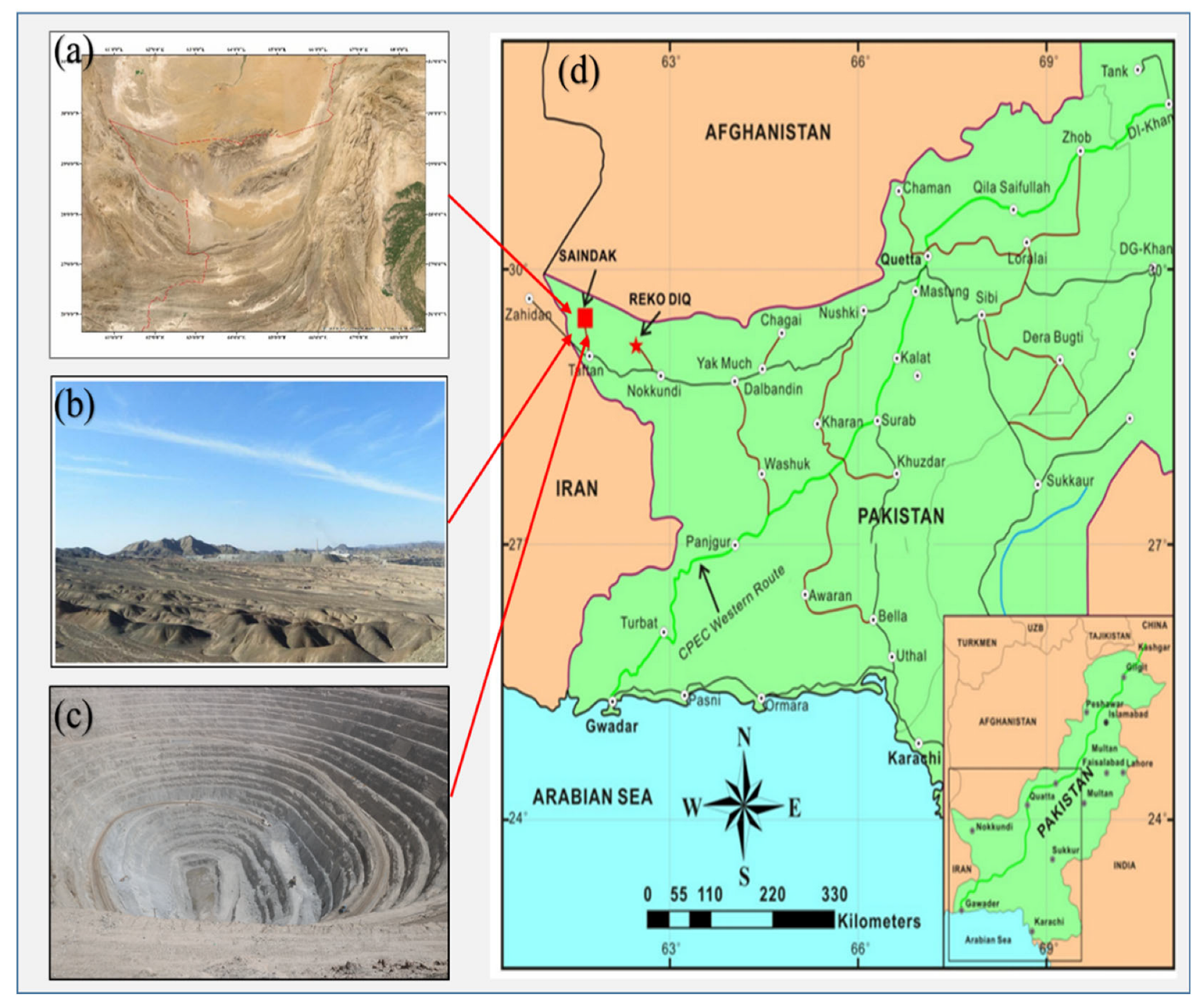
For this study, blasting data were collected from the Saindak Copper-Gold Open-Pit Mine in Pakistan. To assess the impact of blast-induced ground vibrations on slope stability, a total of ten blasting events were analyzed, five from the east slope and five from the west slope. Key blasting geometry parameters, including blast point location, blast hole diameter (mm), blast hole depth (mm), spacing (m), burden (m), stemming length (m), maximum charge per delay (kg), and distance from the blast point (m), were recorded. The average values of these parameters are presented in Table 1. Ground vibration data were measured in terms of PPV, frequency, duration, and vibration velocity. PPV values, initially recorded in mm/sec, were converted to m/sec using standard conversion formulas for simulation. All parameters for each blast event were compiled into a structured dataset for subsequent analysis. Additional slope-specific geotechnical parameters, such as volumetric weight, elastic modulus, Poisson’s ratio, cohesion, and internal friction angle, were obtained from the technical department. However, the laboratory testing was also conducted for cross-validation of these parameters. The equipment used for blast vibration monitoring is shown in Figure 4.
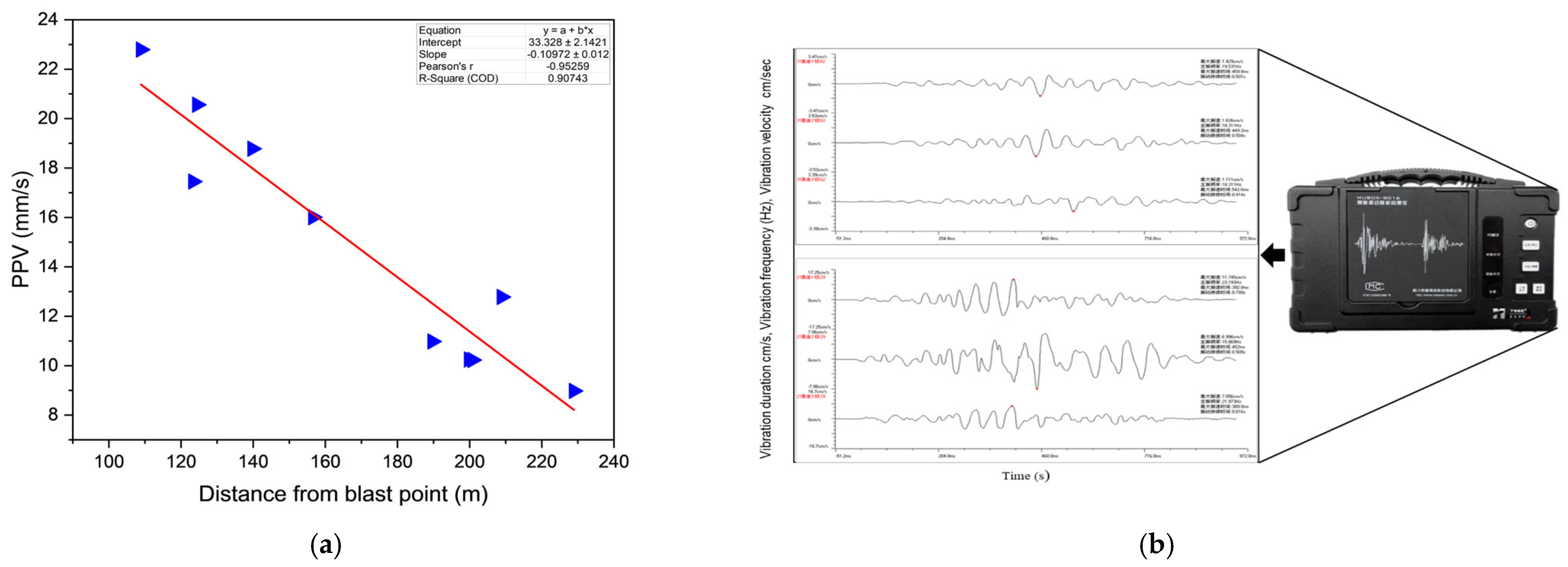
The NUBOX-8016 vibration monitoring system also called intelligent vibration measuring instrument produced by a Chinese company SCTPCKKJ (Chengdu, China) was used to record blast-induced ground vibrations. One unit was installed on the east slope, with two additional sensors positioned near the northern and eastern toes of the pit. These were connected to a TP3V-4.5 three-dimensional velocity-type sensor via a specialized input signal cable. The sensor measured ground vibration magnitudes in three orthogonal directions. Historical monitoring records were provided by the site’s blasting vibration monitoring team. Table 2 summarizes the complete range of vibration parameters recorded during the ten blast events, which served as critical input for evaluating the dynamic effects of blasting on the slope’s FoS. Detailed blasting design data collected for each event were crucial in understanding explosive energy distribution and its correlation with vibration characteristics, particularly PPV, frequency, and the resulting seismic coefficients used in dynamic slope stability assessments. Figure 4a shows the linear regression fit between the actual blast-induced ground vibration PPV and the corresponding distances from the blast site, while Figure 4b displays a photograph of the NUBOX-8016 vibration monitoring equipment used for measuring blast-induced ground vibrations.

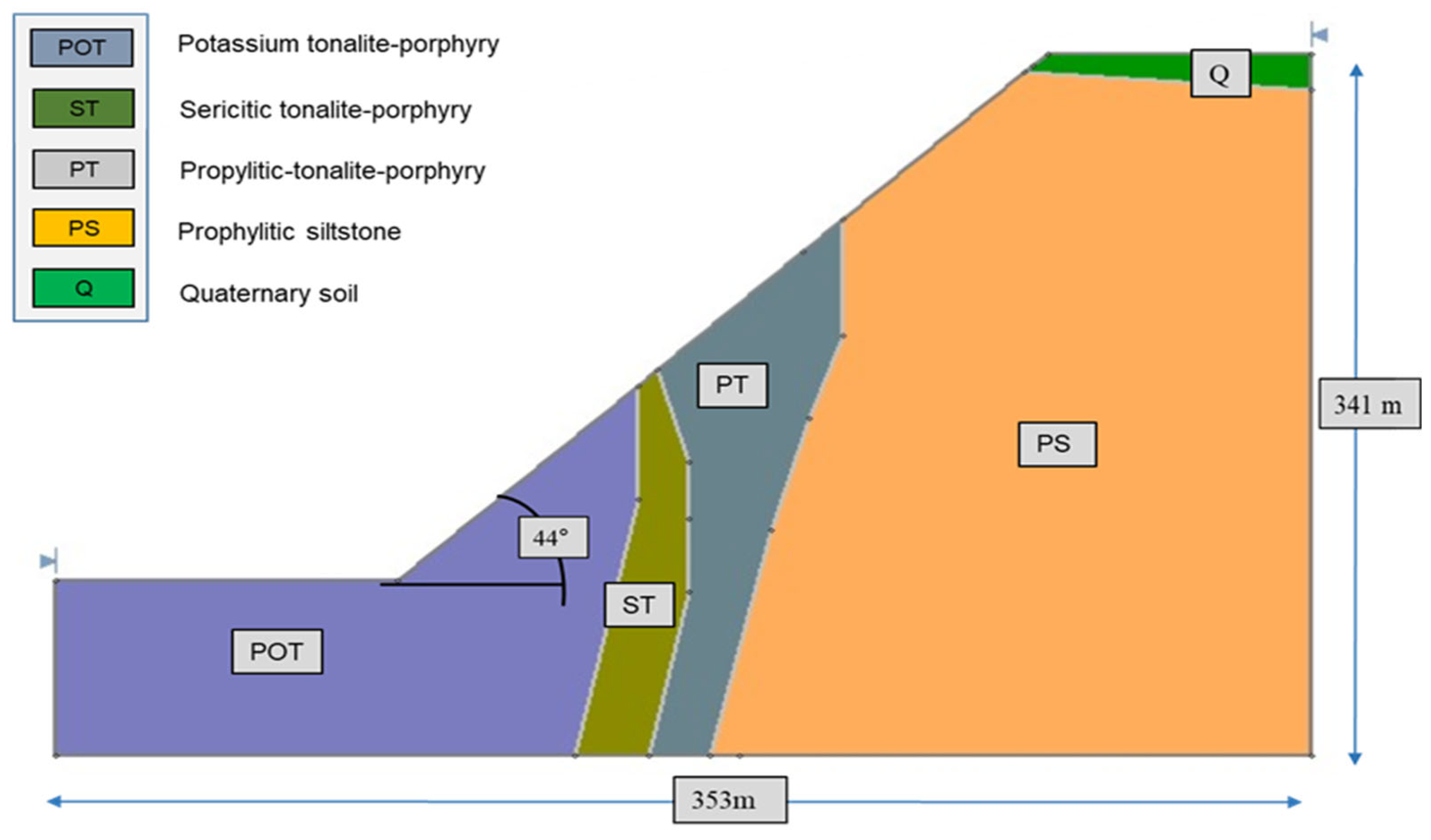
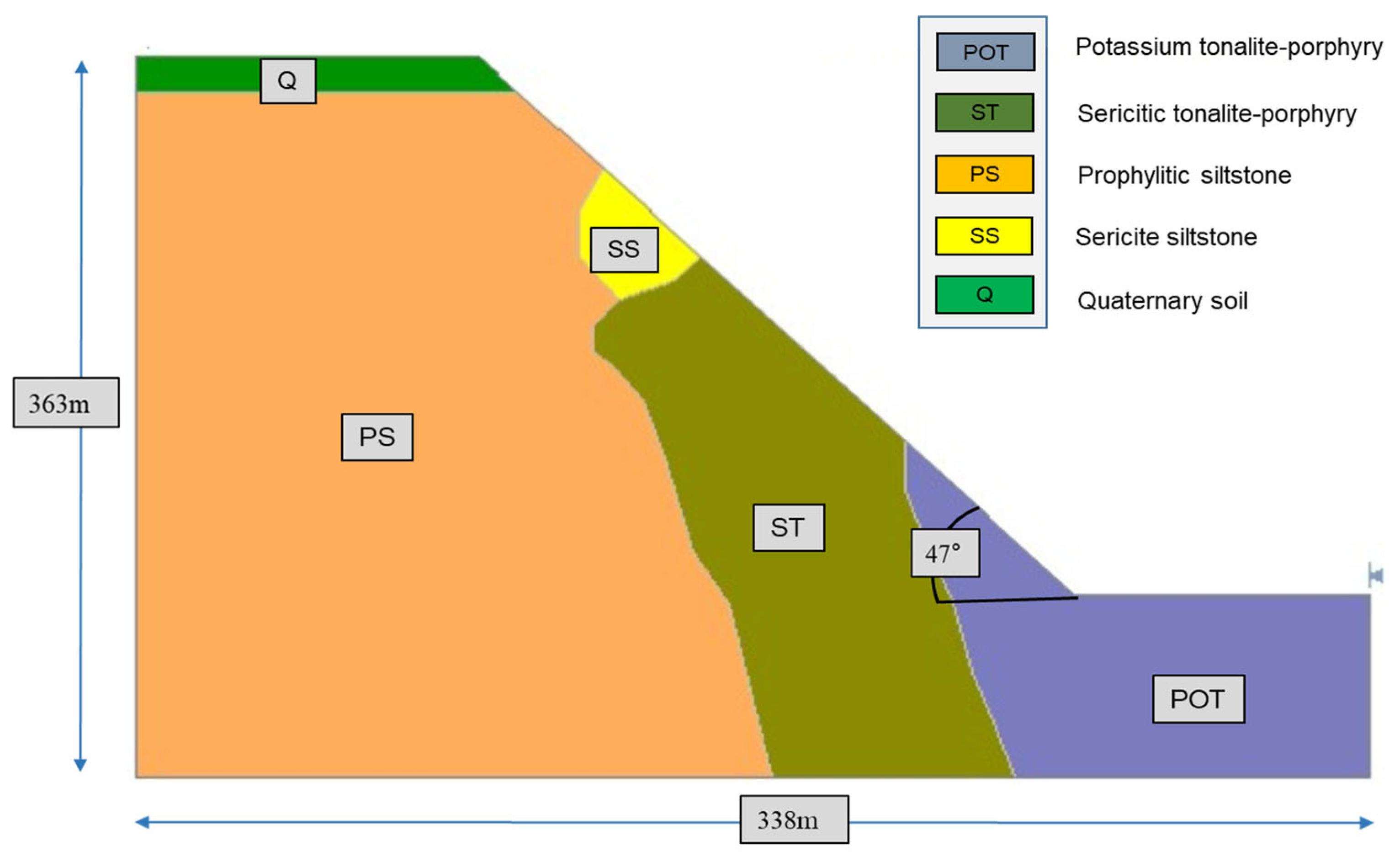
3.2. Slope Geometry and Material Assignment

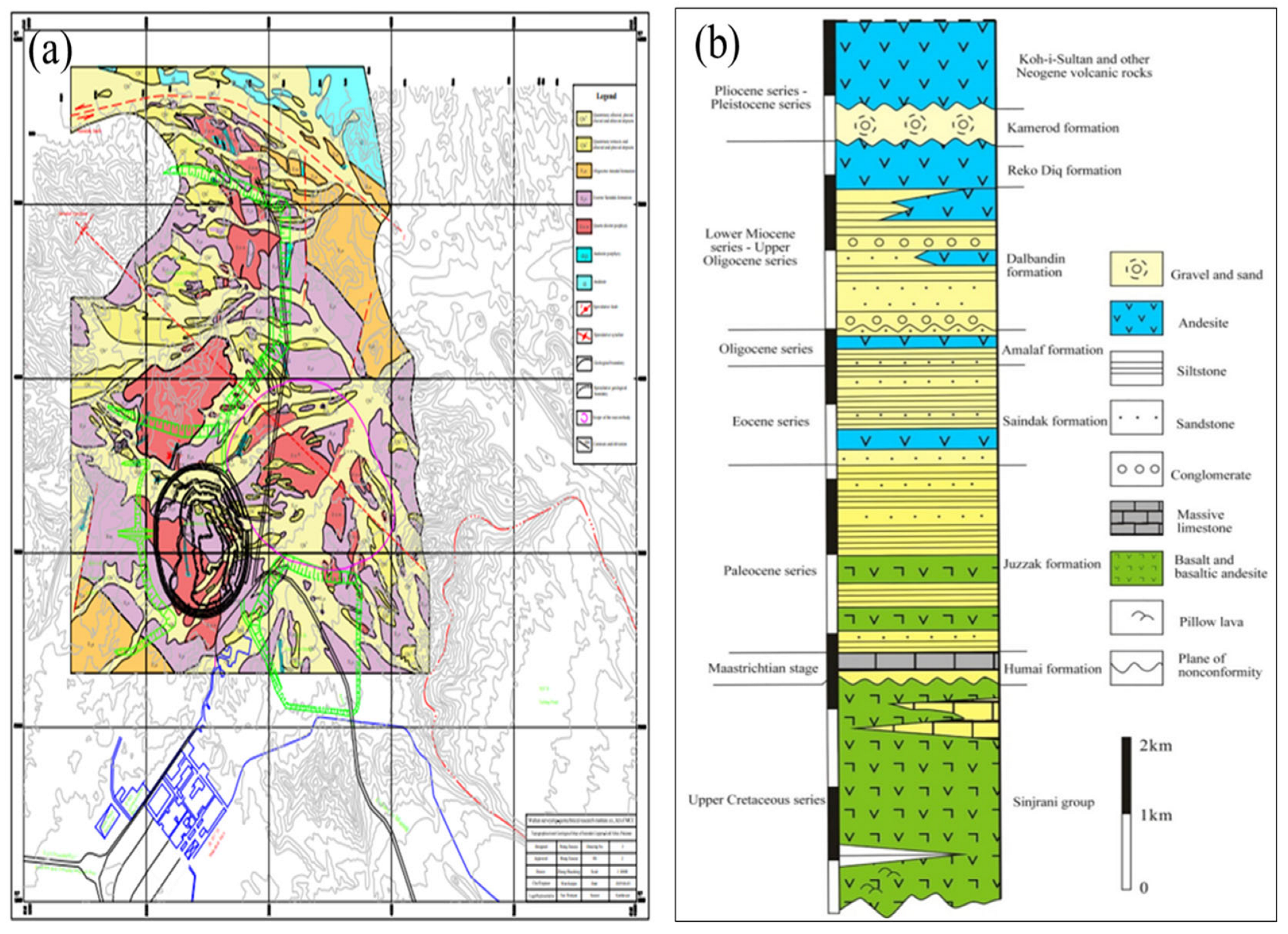
In this case study, two slopes, namely east and west of the south ore body at the Saindak Copper-Gold Mine, were selected for slope stability analysis under both static and dynamic loading conditions. Accurately defining slope geometry is essential for conducting a detailed stability assessment, as geometric parameters directly influence stress distribution, potential failure mechanisms, and overall slope behavior. Accordingly, both slopes were thoroughly surveyed during field investigations. The pit bottom lies at an elevation of approximately 950 m, with the vertical height of the east slope measuring 341 m and the west slope 363 m. The base length of the east slope is 353 m, while that of the west slope is 338 m. The overall slope lengths are 491 m for the east and 496 m for the west. The east slope consists of 28 benches, and the west slope comprises 30 benches. Each bench has an average height of 12 m; however, in the final pit stage, two working benches were merged to create a wider haul road or ramp for accommodating large-diameter mining equipment. The dominant rock types within both slopes include andesite, limestone, and faulted breccia zones. The primary engineering geological formations observed are Quaternary loose soil, Propylitic Siltstone, Sericite Siltstone, Potassium Siltstone, Propylitic-Tonalite-Porphyry, Sericitic-Tonalite-Porphyry, and Potassium-Tonalite-Porphyry. The slopes were divided into discrete material zones based on lithological classification. Each zone was assigned geotechnical properties, including unit weight (kN/m3), cohesion (kPa), internal friction angle (°), elastic modulus (GPa), and Poisson’s ratio. These parameters were obtained from geological records and further validated through laboratory testing.
Slope profiles were developed based on detailed field surveys. While the engineering properties of both slopes are broadly similar, minor differences exist in the lithological composition. These two slopes were selected for detailed analysis due to their increased susceptibility to potential failure. The rock mass in the area is generally strong and massive, exhibiting high internal strength. Overall slope angles range from 44° to 47°, with the east slope averaging 44° and the west slope 47°, depending on bench geometry and rock type. This geometric profile was modeled in SLIDE2 (version 6.0) to evaluate the FoS under different loading conditions and to assess the risk of slope failure induced by blasting operations.

3.3. Slope Stability Analysis Using SLIDE Software

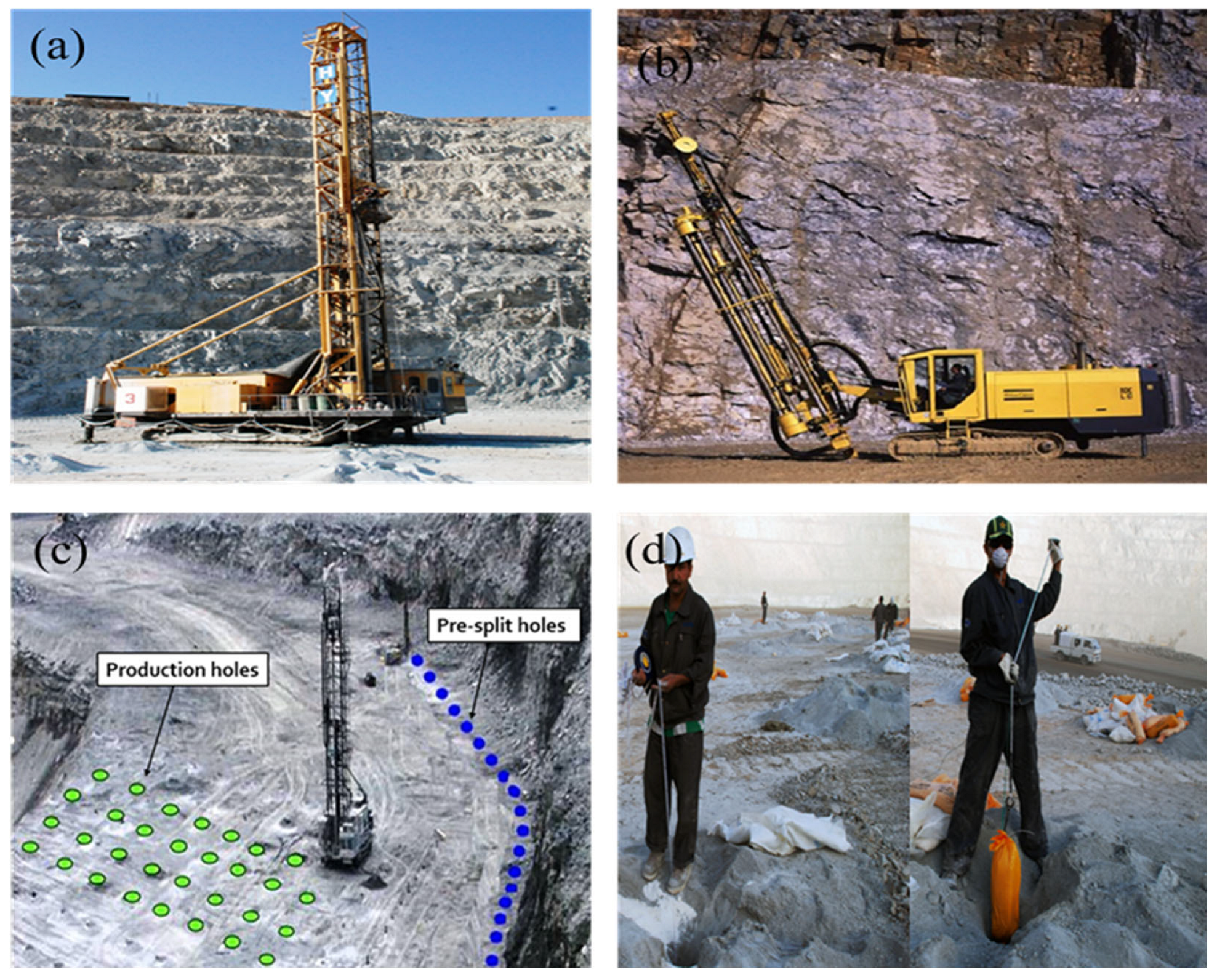
This section outlines the methodology used to evaluate slope stability using SLIDE2 version 6.0, a two-dimensional (2D) limit equilibrium software developed by Rocscience. The software was employed to analyze the FoS under both static and dynamic loading conditions, incorporating actual blast-induced ground vibration data to assess its impact on slope performance. Two slopes from the open-pit mine, designated as the east slope and west slope, were selected for analysis based on recommendations from mine officials. These slopes were identified as the most vulnerable to potential failure due to their geometric configuration and exposure to frequent blasting activities. SLIDE 6.0 supports a wide range of LEMs for analyzing both circular and non-circular slip surfaces and allows for detailed modeling of slope geometry, material zoning, pore water pressure, support systems, and external loading, including seismic forces. The analysis employed four widely recognized LEM techniques available in SLIDE: the Fellenius, Bishop Simplified, Janbu Simplified, and Spencer methods. These were initially applied under static conditions to determine the baseline FoS values for both slopes.
To simulate dynamic conditions, seismic loading was introduced using horizontal and vertical seismic coefficients. In line with standard mine safety practices [37], the vertical component was assumed to be 50% of the horizontal force. The seismic coefficient (K) was calculated using measured ground vibration frequency and gravitational acceleration. The Mohr–Coulomb failure criterion was adopted for all materials, and slope-specific mechanical properties were defined separately for the east and west slopes to account for lithological variability. The modeling process in SLIDE involved several stages, including defining slope geometry, assigning boundary conditions, inputting geotechnical parameters, and incorporating key topographic and geometric features such as slope height, and surface profiles. The geological profile and geometry of the stratified formations along the east and west slopes are illustrated in Figure 5 and Figure 6. The external model boundaries were constructed based on field survey data and coordinate measurements. After completing both static and dynamic simulations, FoS values were computed for each method using average, minimum, and maximum ground vibration inputs. The results were compiled and compared for both slopes to quantify the reduction in stability under dynamic conditions.

3.4. The Limit Equilibrium Method

LEM is one of the most widely used and fundamental approaches for slope stability analysis due to its simplicity, low computational complexity, ease of implementation, and fast processing time [30,38]. It is effectively applied under both static and dynamic conditions, in two-dimensional and three-dimensional slope geometries, using either block or slice-based analysis techniques. LEM estimates the FoS by evaluating the equilibrium conditions of a potential sliding mass along a predefined failure surface. The method assumes equilibrium by balancing either forces or moments and can handle both circular and non-circular slip surfaces [39]. Several LEM techniques have been developed, with the most commonly used methods being Fellenius (Ordinary), Bishop Simplified, Janbu Simplified, and Spencer. These approaches typically yield closely matching FoS results, with differences generally less than 6% [40]. The basic form of the FoS calculation in LEMs is:
F . S =   R e s i s t a n c e   f o r c e s A p p l i e d   f o r c e s  
A key feature of LEM is its reliance on the Mohr–Coulomb failure criterion to estimate shear strength and resistance along potential failure surfaces. This criterion, based on total or effective stress parameters (cohesion and internal friction angle), is widely regarded as applicable for analyzing slope stability in both soil and rock. In this study, slope stability was evaluated under blast-induced dynamic loading using LEM, assuming a circular failure surface passing through the critical sections of the east and west pit slopes. The Bishop, Janbu, Fellenius, and Spencer methods were employed to calculate the FoS and identify likely failure mechanisms under dynamic conditions [35].

3.4.1. The Fellenius Method

The Fellenius method, also known as the Ordinary Method of Slices, was introduced in 1927. It is the simplest form of LEM and involves dividing the potential sliding mass into vertical slices [26]. This method can be used under both static and seismic loading conditions [41]. The equation for calculating FoS in this method is:
F = W cos α tan ( φ ) + c L W sin α + k h W c o s ( α )  
where W′ represents the effective weight of the sliding mass, typically acting normal to the slope surface. α is the angle of the base of the potential sliding surface (i.e., the slope angle), while φ denotes the internal friction angle of the slope material (in degrees). c refers to the cohesion of the material, and L is the base length of the potential slip surface. The term k h stands for the horizontal seismic coefficient, used to represent the dynamic load due to blast-induced ground vibrations. In this equation, the numerator represents the resisting forces contributed by cohesion and friction, whereas the denominator accounts for the driving forces, including gravitational and seismic effects.

3.4.2. The Bishop Simplified Method

The Bishop Simplified method considers interslice normal forces and assumes negligible shear forces between slices. It provides accurate FoS estimates even though it does not fully satisfy all static equilibrium equations [42,43]. The FoS is calculated using:
S F = c A + ( W cos ( ψ p ) μ υ sin ( ψ p ) ) t a n ( φ ) W sin ( ψp ) + k h W c o s ( ψ p )  
where ψₚ represents the inclination angle of the base of the sliding slice or failure surface, μ pore water pressure, and υ denotes the velocity-related dynamic coefficient. Other symbols as previously defined.

3.4.3. The Janbu Simplified Method

The Janbu method is effective for non-circular failure surfaces. It assumes that normal forces act at the center of the slice base and neglects interslice shear [44,45]. The FoS is given by:
N γ = 1.3 γ c ( t a n φ + 0.5 ) ( 1 s i n φ ) 2  
where Nγ describes the bearing capacity factor related to the unit weight of the material (γ), and γ unit weight of the soil or rock. c   a n d   describes the material strength parameters.

3.4.4. The Spencer Method

The Spencer method assumes both force and moment equilibrium and applies a constant ratio between interslice shear and normal forces. It offers high accuracy for both circular and complex non-circular slip surfaces [46,47]. The FoS is calculated as:
N γ = 1.3 γ c   t a n ( 0.5 ) ( 1 s i n ϕ ) 2 1 + 0.2 B D  
where γ ,   c ,   represent the rock strength properties, and B and D denote the width and length of the slip surface.

3.5. Seismic Coefficient Calculation

PPV data were collected in the field using vibration monitoring equipment for each blast event, recorded in millimeters per second (mm/s). To compute the corresponding horizontal seismic coefficients k h for use in pseudo-static slope stability analysis, the peak particle acceleration (PPA) was first calculated using the formula:
P P A = 2 π f · P P V  
where f is the dominant vibration frequency (Hz) and PPV is converted to meters per second. The pseudo-static horizontal seismic coefficient k h was then obtained as:
k h = π r 2 = P P A g  
where g = 9.81 m/s2 is gravitational acceleration. A conservative vertical seismic coefficient k v = 0.5 × k h was adopted for the dynamic analysis, assuming it to be half the horizontal seismic coefficient. This approach follows the recommendation by Morales et al. [48], who demonstrated that such an assumption has minimal impact on stability results under typical seismic conditions. The final calculated dynamic load values for each blast event are presented in Table 3.

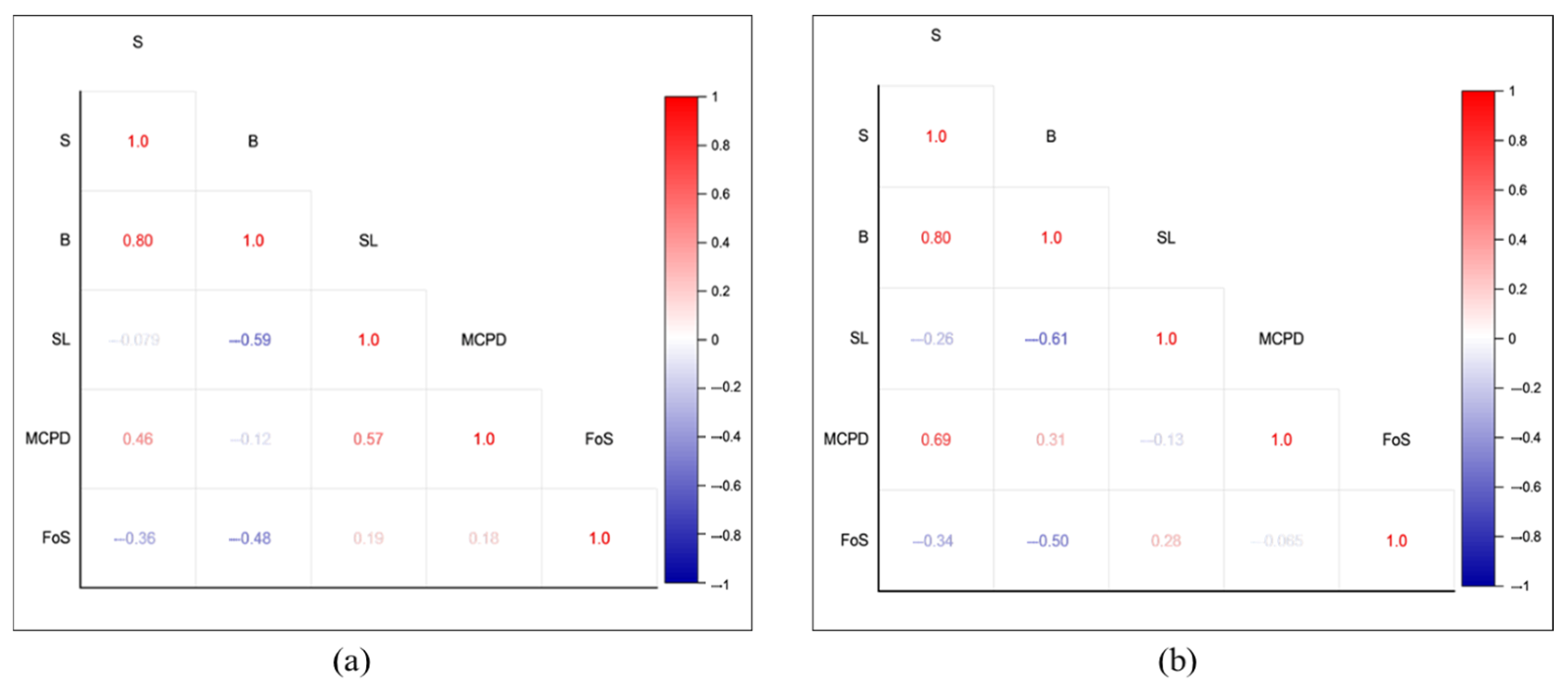
3.6. Correlation Analysis

In this study, two statistical correlation techniques, namely Pearson correlation coefficient (PCC) and Spearman rank correlation coefficient (SCC) were employed to assess the relationship between blasting parameters and slope stability, measured by the FoS. The Pearson correlation coefficient measures the strength and direction of a linear relationship between two continuous variables and is suitable for normally distributed data [49,50]. It is defined by the following formula:
r p = x i x ¯ ( y i y ¯ ) 2 ( x i x ¯ ) ( ( y i y ¯ ) 2 )
where x i and y i are the individual sample points, and x ¯ and y ¯ are the mean of variables x and y, respectively.
The Spearman rank correlation coefficient is a non-parametric measure that evaluates the monotonic relationship between two variables, without assuming normal distribution or linearity [51,52]. It is computed using:
r s = 1 6   d i 2 n n 2 1  
where d i is the difference between the ranks of each pair, and n is the number of observations.
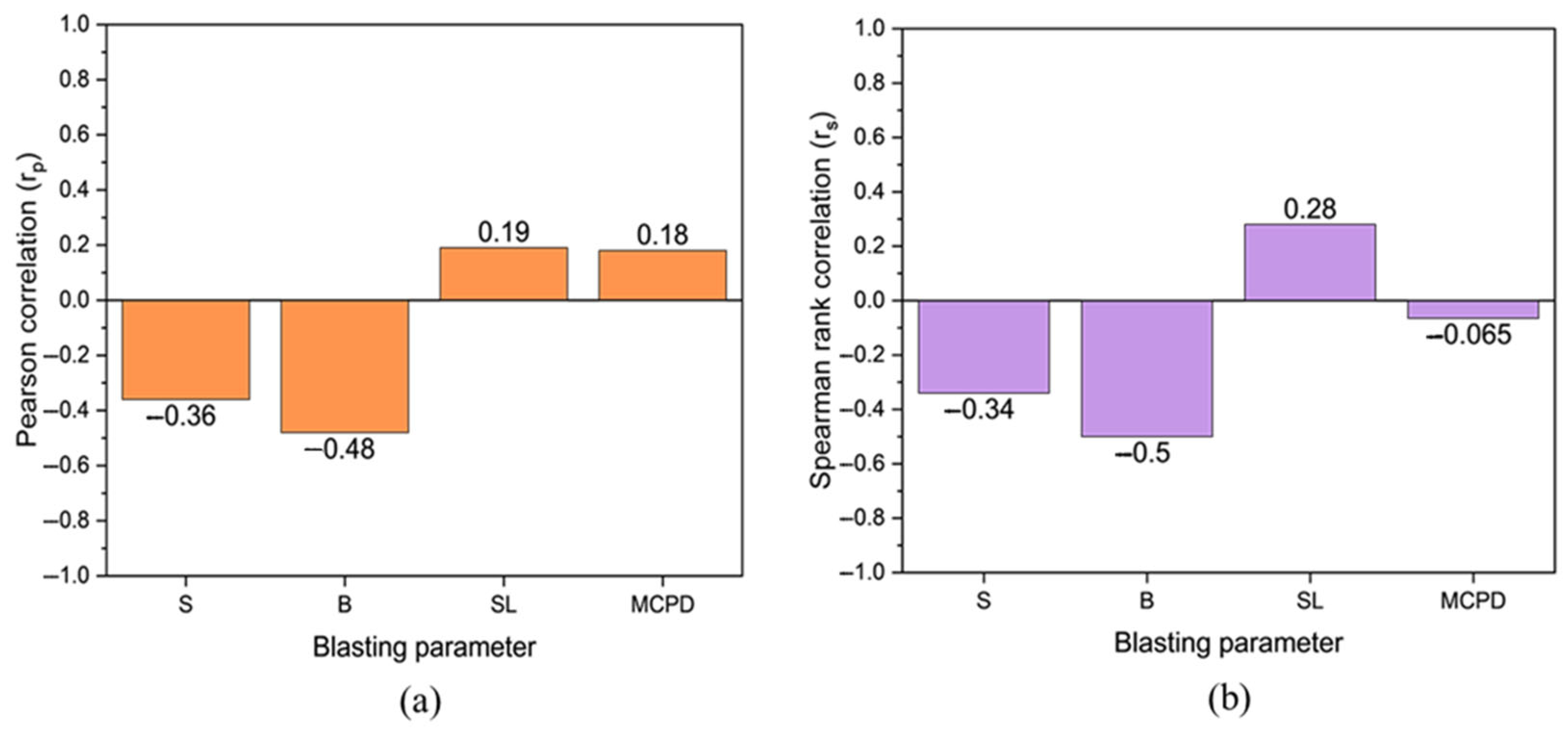
These correlation methods were applied to identify both linear and non-linear associations between blasting variables including spacing (S), burden (B), stemming length (SL), maximum charge per delay (MCPD) and the corresponding FoS values. The correlation coefficients range from −1 to +1, where +1 indicates a perfect positive correlation, −1 indicates a perfect negative correlation, 0 implies no correlation. Higher absolute values of the correlation coefficients suggest stronger relationships between the variables. The results help determines whether variations in blasting parameters significantly influence slope stability. Figure 7 presents the correlation matrix plots for both Pearson and Spearman analyses across all input variables and FoS.

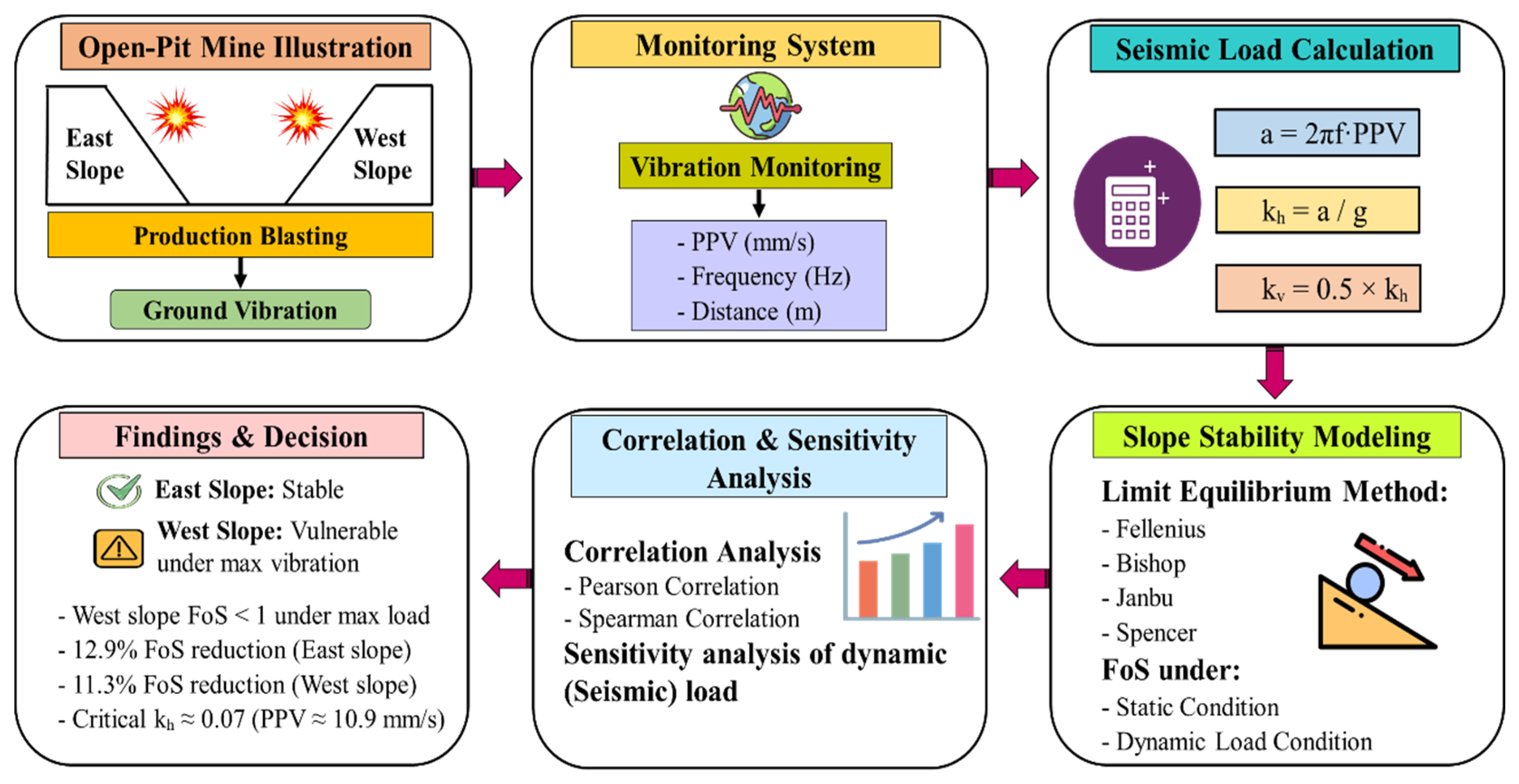
3.7. The Study Workflow and the Methodological Framework

This section outlines the systematic approach adopted in this study to evaluate the effects of blasting-induced ground vibrations on slope stability. The workflow integrates field data collection, laboratory testing (validation), numerical modeling, correlation, and statistical analysis to assess the FoS under both static and dynamic conditions. A step-by-step methodology was developed, as illustrated in Figure 8, to ensure consistency and reliability in the analysis. This framework serves as the basis for all subsequent modeling, correlation, and sensitivity evaluations discussed in later sections.

4. Results and Discussion

4.1. Geotechnical and Mechanical Properties of the Rock Mass

The geotechnical parameters used in this study were primarily obtained from geological and geotechnical records provided by the Saindak Copper-Gold Mine management. Although these properties were not derived from an extensive on-site testing campaign, laboratory validation was conducted to ensure their reliability. Three representative rock samples from each lithological unit were collected from both the east and west pit slopes. These samples were tested under controlled laboratory conditions to determine key mechanical properties, including volumetric weight, elastic modulus, Poisson’s ratio, cohesion, and internal friction angle. The rock types analyzed include Propylitic Siltstone, Sericite Siltstone, Potassium Siltstone, Propylitic-Tonalite-Porphyry, Sericitic-Tonalite-Porphyry, Potassium-Tonalite-Porphyry, and Quaternary deposits. The average values for each geotechnical parameter are presented in Table 4. Results indicate that the mechanical properties are generally consistent across both slopes, with only minor variations attributed to lithological heterogeneity. Among the investigated rock types, Propylitic Siltstone exhibited the most favorable geotechnical properties, including a volumetric weight of 27.37 kN/m3, elastic modulus of 5.86 GPa, Poisson’s ratio of 0.168, cohesion of 370 kPa, and an internal friction angle of 35°. These values suggest moderate strength and stiffness, making Propylitic Siltstone one of the most mechanically stable formations present within the pit.
In contrast, the Quaternary deposits are mostly unconsolidated surface materials, demonstrating the weakest mechanical behavior. These deposits exhibited a volumetric weight of 18.00 kN/m3, a low elastic modulus of 0.15 GPa, a relatively high Poisson’s ratio of 0.350, cohesion of 45 kPa, and an internal friction angle of 19°. Such values are typical of loose, weathered materials and indicate limited strength and stability, particularly under dynamic loading conditions. It is noteworthy that more than 70% of the slope composition comprises Propylitic Siltstone, which plays a critical role in maintaining slope stability, even under repeated blast-induced vibrations. The mechanical strength of PS substantially contributes to resisting both static and dynamic forces. The consistency of these favorable properties across both slopes supports the observed overall pit stability. However, the presence of weak Quaternary materials near the slope crest requires special attention during blasting and slope design to prevent localized instability. In summary, the geotechnical assessment emphasizes the dominance and mechanical reliability of Propylitic Siltstone in the pit’s geological framework, which is a key factor in ensuring long-term slope stability. Conversely, the weak mechanical characteristics of the Quaternary layer of the slope necessitate design caution, especially in surface blasting operations.

4.2. Slope Stability Under Static Conditions

A static slope stability analysis was performed to assess the inherent stability of the east and west pit slopes in the absence of external dynamic loading. Four classical LEM methods including Fellenius, Bishop Simplified, Janbu Simplified, and Spencer were employed to evaluate both slope profiles. The analysis utilized the average values of mechanical properties corresponding to the respective rock masses as input parameters. For the east slope, the lowest FoS was obtained using the Janbu method, which yielded a value of 1.401. The highest FoS was recorded using the Spencer method, with a value of 1.502 as illustrated in Figure 9. The Fellenius and Bishop methods produced closely aligned FoS values of 1.419 and 1.500, respectively, indicating minimal variation across methods. In the case of the west slope, the Janbu method again yielded the lowest FoS, with a value of 1.158 (Figure 10). The highest value was recorded using the Bishop method, at 1.248. The Fellenius and Spencer methods produced FoS values of 1.173 and 1.240, respectively.
The greater stability observed in the east slope is attributed to its more homogeneous material distribution and the presence of the Propylitic-Tonalite-Porphyry (PT) formation. As illustrated in the slope geometry model, the PT unit is characterized by high-strength geotechnical properties specifically, a volumetric weight of 26.98 kN/m3, cohesion of 390 kPa, and an internal friction angle of 35°, all of which positively influence slope performance. Additionally, the east slope has a gentler average slope angle of 44°, compared to the steeper 47° observed in the west slope, further contributing to its higher stability. It is well established in geotechnical literature that steeper slope angles generally reduce stability [53]. Overall, the results indicate that both slopes remain stable under static loading conditions, with all calculated FoS values exceeding the minimum threshold recommended by blasting and slope safety guidelines [54]. Therefore, in the absence of seismic or blast-induced forces, both the east and west slopes can be considered structurally sound.

4.3. Slope Stability Under Dynamic (Seismic) Load Condition

To evaluate the impact of blast-induced ground vibrations on slope stability, a pseudo-static slope stability analysis was performed using the LEM based on the Mohr–Coulomb failure criterion. In this approach, horizontal seismic coefficients ( k h ) were calculated from field-monitored ground vibration data, specifically PPV and vibration frequency. These coefficients represent the equivalent horizontal acceleration acting on the slope during blasting events. The seismic coefficient ( k h ) was derived using the relation ( k h = a / g , where a is the acceleration computed from PPV and frequency, and g = 9.8   m / s 2 is the gravitational constant. The corresponding vertical seismic coefficient ( k v ) was assumed as half the horizontal component, following standard pseudo-static design practices: ( k v = 0.5 k h ) [48,55]. A summary of the average dynamic input parameters for the east and west slopes, along with the corresponding seismic coefficients, is presented in Table 5.
k h k v The highest seismic load observed was k h = 0.14 recorded during the E1 blast, while the lowest was k h = 0.02 observed during the W5 blast. Based on these seismic coefficients, FoS values were calculated using four LEM techniques such as Fellenius, Bishop, Janbu, and Spencer under three loading scenarios: without dynamic load, and with minimum, average, and maximum seismic loads. The computed FoS values under both static and dynamic conditions for the east and west slopes are summarized in Table 6.
Under average seismic loading, the lowest FoS was recorded on the west slope using the Janbu method, yielding a value of 1.216 (Figure 11). In contrast, the highest FoS was observed on the east slope using the Spencer method, with a value of 1.308. Among the LEM applied, the Spencer method consistently produced the highest FoS values. This observation is supported by previous studies [56,57], which identify the Spencer method as one of the most accurate due to its ability to satisfy all the conditions of static equilibrium: horizontal force, and moment balance. Figure 12 presents the comparison of FoS values obtained by using all four selected limit equilibrium methods, in which the Spencer methods shows the highest FoS values among all. This full-equilibrium compliance allows for more realistic modeling of complex slip surfaces and inter-slice forces, making it more suitable for dynamic slope assessments compared to simpler methods such as Fellenius or Janbu. However, under maximum seismic loading, FoS values on the west slope fell below the critical stability threshold of 1.0, indicating a potential failure state. Specifically, the Fellenius and Janbu methods yielded FoS values of 0.979 and 0.961, respectively. These findings suggest that while both slopes remain stable (yielded FoS > 1) under average dynamic conditions, the west slope is significantly more vulnerable to high-energy ground vibrations. This increased susceptibility is primarily due to its steeper slope geometry. The observed reduction in FoS after applying dynamic loads was approximately 12.9% for the east slope and 11.3% for the west slope. This demonstrates the measurable and adverse impact of blasting-induced vibrations on slope stability. The reduction values are summarized in Table 7. In conclusion, while the current blasting practices at the mine generally maintain slope stability, the west slope requires closer monitoring and control, especially during high-energy blasting events. Further detailed analysis is recommended to isolate the influence of individual factors such as slope geometry, bench configuration, and blast design on vibration intensity and slope response. This will help optimize future slope designs and blasting strategies to ensure continued safety in open-pit operations.

4.4. Correlation Analysis Results

The results of the Pearson correlation coefficient, presented in Figure 13a, highlight the direction and strength of relationships between blasting design parameters and the FoS. Specifically, stemming length (SL) and maximum charge per delay (MCPD) exhibit a positive correlation with FoS, with values of 0.19 and 0.18, respectively, suggesting a slight stabilizing effect. Conversely, spacing (S) and burden (B) show a negative correlation with FoS, at −0.36 and −0.48, indicating a potential reduction in slope stability as these parameters increase. In Figure 13b, the Spearman rank correlation coefficient reveals a similar trend but with variations in strength and ranking. Stemming length (SL) maintains a positive correlation with FoS (0.28), whereas spacing (S), burden (B), and MCPD exhibit negative correlations at −0.34, −0.50, and −0.065, respectively. Among the blast design parameters, burden (B) exhibits the most significant negative influence on slope stability under dynamic loading, highlighting its critical role in vibration control. As the distance between the blasthole and the free face, burden directly affects energy distribution—excessive burden may cause underbreak and high PPV due to poor energy release, while too small a burden can lead to flyrock and slope damage. Therefore, optimizing the burden distance is essential for reducing peak particle velocity, enhancing blasting efficiency, and minimizing the risk of vibration-induced slope instability in open-pit mines.

4.5. Sensitivity Analysis of Dynamic (Seismic) Load

A sensitivity analysis was conducted to evaluate the effect of dynamic loading, specifically blast-induced ground vibrations, on slope stability by varying the peak particle acceleration (PPA)/horizontal seismic coefficient k h . The primary objective was to assess how different intensities of ground motion influence the probability of slope failure and the likelihood of instability. This analysis was performed using SLIDE software, wherein k h values were systematically varied while keeping material properties constant. The results are presented through cumulative and relative frequency distributions to illustrate the progression of failure probability under increasing dynamic loads.
In the first stage, a cumulative probability distribution was generated across a range of k h values. The results clearly show that the probability of failure increases with rising seismic loads. For example, at k h = 0.50, the failure probability was 0%, which increased to 9.3% at k h = 0.0619, and exceeded 36% at k h = 0.0847. The highest observed failure probability was over 76% at k h = 0.1124. Figure 14 illustrates the cumulative distribution of slope failure under blast-induced dynamic loading. These findings underscore the strong correlation between increasing vibration intensity and declining slope stability.
In the second stage, a relative frequency distribution was analyzed to identify the critical k h range where slope failure is most likely to occur. The peak relative frequency was observed between k h = 0.07 and k h = 0.095, with a frequency range of approximately 7.4% to 7.6%. This range represents a transitional zone where the slope shifts from a marginal stability to potential failure, making it a critical threshold for vibration control. These sensitivity results reinforce the findings from the dynamic loading analysis. Although both the east and west slopes remain stable under the current blast design parameters, the trend in FoS values clearly shows a downward trajectory with increasing seismic load. This effect is particularly pronounced on the west slope, which already exhibits a lower baseline FoS. These results indicate that extra caution is necessary when planning blasting operations on the west slope. Figure 15 presents the dynamic response frequency to blast-induced dynamic loads.
The analysis also emphasizes the importance of controlling critical blasting parameters, especially charge per delay and blast pattern, as these directly influence the intensity of ground vibrations. Optimizing these parameters by rock mass properties and slope geometry (such as slope angle) can significantly mitigate excessive vibrations and help maintain slope stability. In conclusion, the sensitivity analysis reveals that the slope system becomes highly responsive and vulnerable to failure beyond a seismic coefficient of approximately k h ≈ 0.07. This threshold corresponds to a PPV of approximately 10.9 mm/s, based on a vibration frequency range of 8.76 to 9.31 Hz. These thresholds serve as critical design limits for ensuring safe blasting operations and guiding future vibration control strategies.

5. Conclusions

Blasting is a widely adopted and cost-effective technique for rock fragmentation and excavation in open-pit mining. However, uncontrolled or poorly executed blasting operations can produce excessive ground vibrations, which may compromise slope stability and pose risks to nearby infrastructure, equipment, and personnel. Therefore, evaluating the impact of blast-induced ground vibrations on slope stability is essential for ensuring safe and sustainable mining operations. This study presents a comprehensive field investigation conducted at the Saindak Copper-Gold Open-Pit Mine in Pakistan, focusing on slope performance under both static and dynamic (pseudo-static) loading conditions. The investigation incorporated detailed field data, including pit geometry, lithological characteristics, blast design parameters, and ground vibration records. Laboratory testing was conducted on rock samples to validate the geomechanical properties used in the analysis. Slope stability was assessed using SLIDE2 6.0 software, and the influence of key blasting parameters on slope behavior was quantified using both Pearson and Spearman correlation analyses. Four standard limit equilibrium methods (LEMs)—Fellenius, Bishop, Janbu, and Spencer, based on the Mohr–Coulomb failure criterion, were employed to evaluate the FoS under varying load scenarios. Additionally, a sensitivity analysis was performed to determine the cumulative distribution of slope failure and dynamic response frequency under increasing seismic loads. The key findings and recommendations derived from this analysis are summarized below:
  • All the blasting geometry parameters, including spacing, burden, stemming length, charge per delay, and distance from the blast point, were incorporated into the analysis. The average recorded ground vibration values were: PPV = 14.88 mm/s, frequency = 9.43 Hz, duration = 1.51 s, and vibration velocity = 14.29 mm/s.
  • Field investigations revealed that the pit slopes are primarily composed of moderate to strong rock types, such as Propylitic Siltstone, Sericite Siltstone, Potassium Siltstone, and various Tonalite-Porphyry formations, with a thin Quaternary layer at the surface. These materials exhibit moderate to high strength, contributing to overall slope stability.
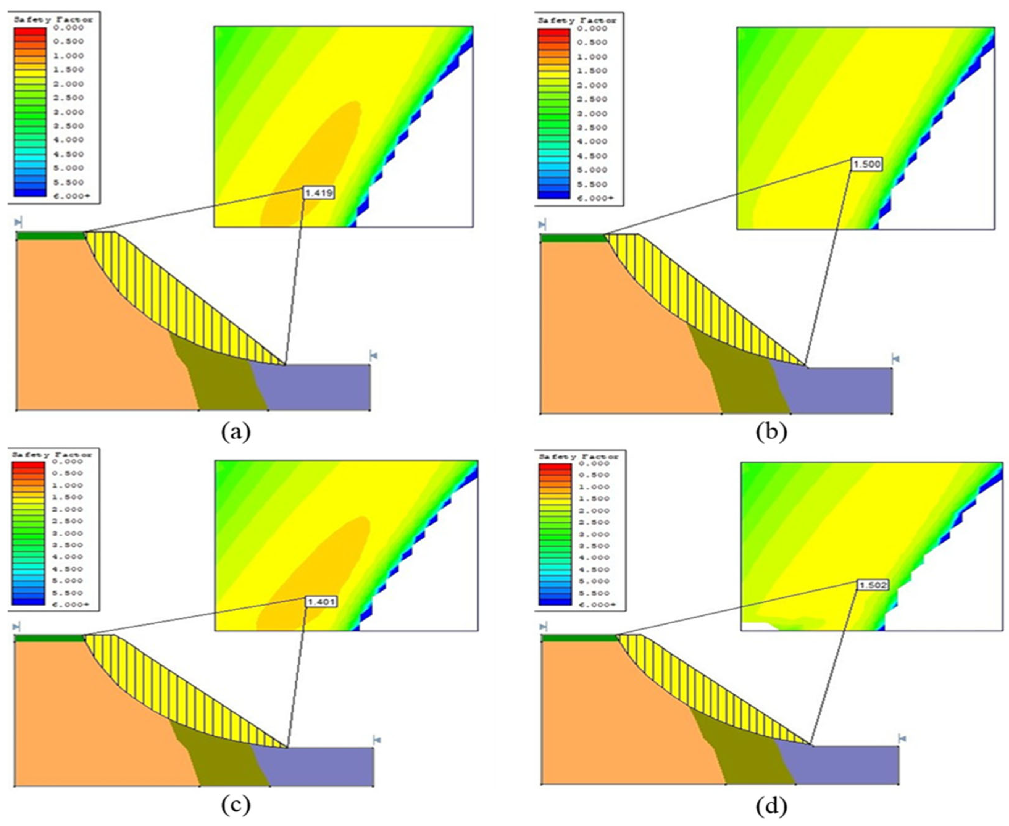
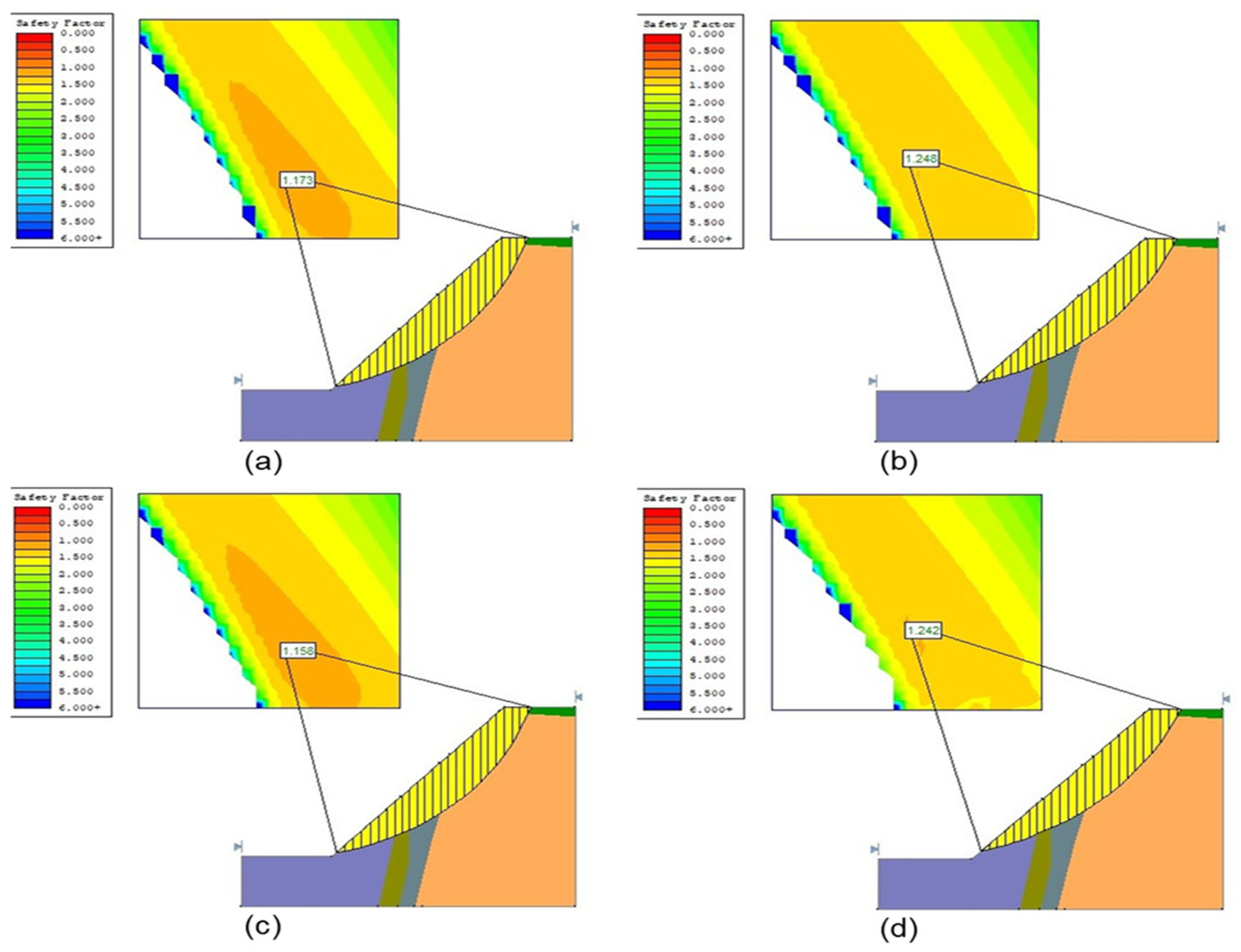
  • Under static conditions, both the east and west slopes exhibited stable behavior, with all FoS values exceeding 1.0. The east slope showed slightly higher stability, with FoS ranging from 1.401 to 1.502, compared to 1.158 to 1.242 for the west slope primarily due to a lower average slope angle (44° vs. 47°).
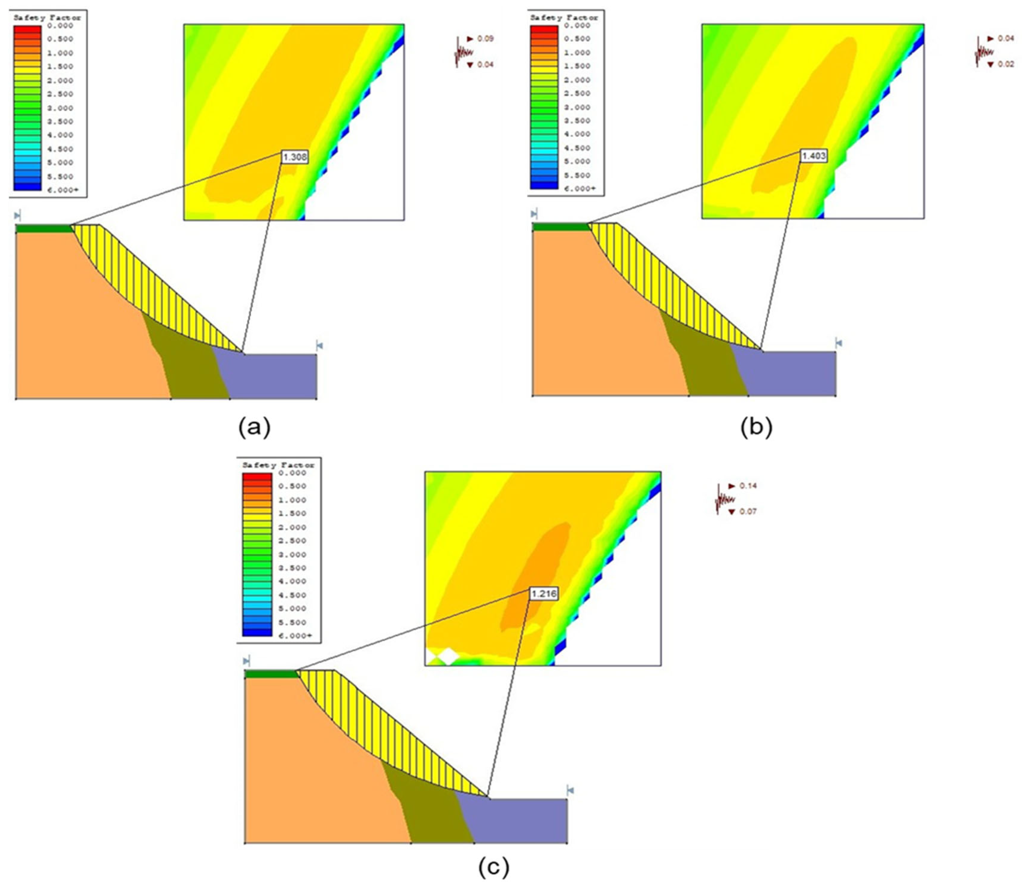
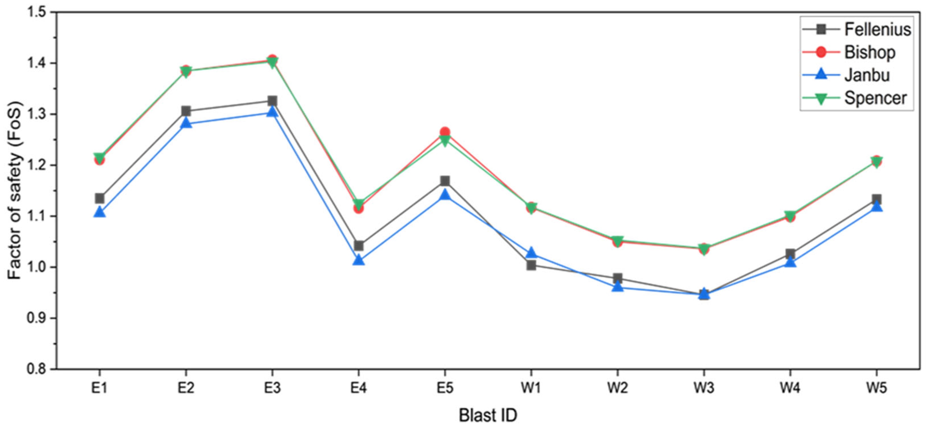
  • Under average blast-induced dynamic loading, both slopes remained stable (FoS > 1). However, under maximum seismic loading, the west slope became potentially unstable, with FoS values falling below 1.0 in the Janbu and Fellenius methods only with values of 0.961 and 0.979, respectively. The Spencer method consistently produced the highest FoS under dynamic conditions (1.308 for east, 1.102 for west), confirming its robustness in seismic analysis. Slope angle was found to be a significant factor in stability performance. Dynamic loading resulted in a reduction in FoS by approximately 12.9% for the east slope and 11.3% for the west slope, emphasizing the need for slope angle optimization in design phases.
  • Correlation analysis revealed that stemming length (SL) positively influences slope stability, while burden (B) and spacing (S) are negatively correlated with the FoS. Among all parameters, burden showed the strongest negative impact on FoS, identifying it as a critical factor in blast-induced slope vulnerability. Among all parameters, burden showed the strongest negative effect on FoS, identifying it as a critical factor in blast-induced slope vulnerability.
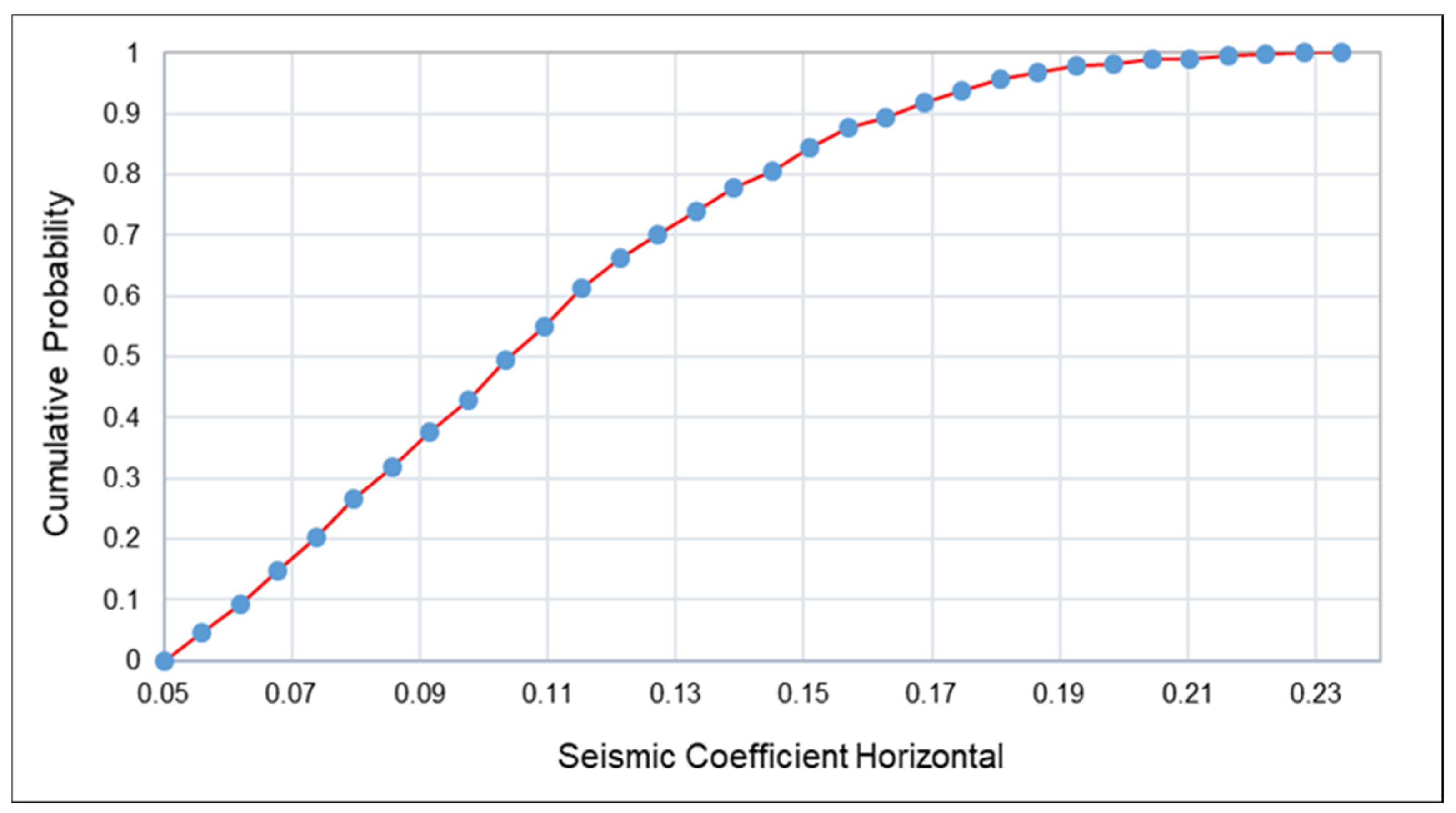
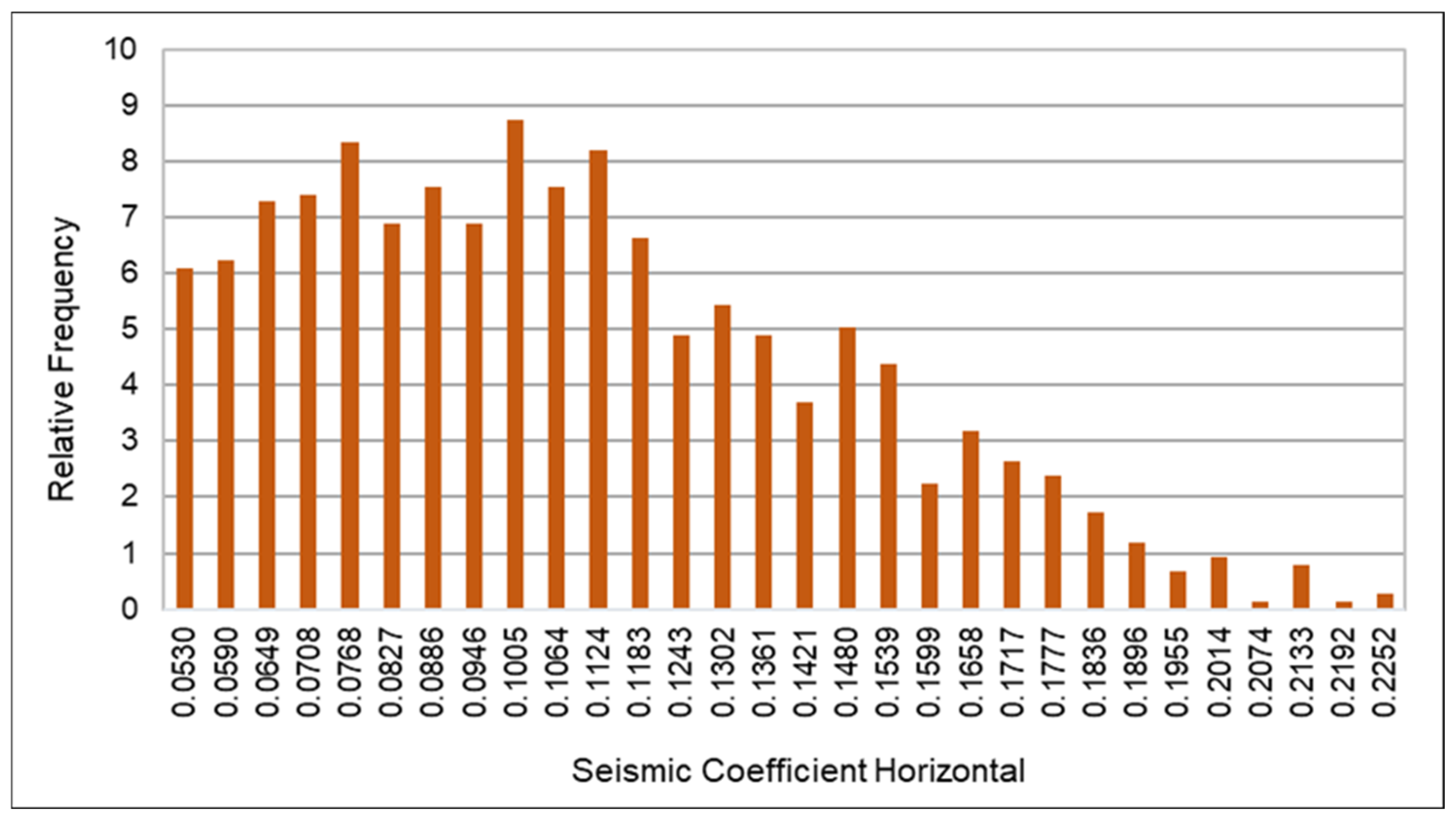
  • Sensitivity analysis further revealed that slope stability deteriorates rapidly when the horizontal seismic coefficient (kₕ) exceeds 0.07, corresponding to a PPV of approximately 10.9 mm/s within a vibration frequency range of 8.76 to 9.31 Hz. These thresholds represent critical design limits for ensuring safe blasting operations and informing future vibration control strategies. This underscores the importance of precisely managing blasting parameters, particularly the maximum charge per delay, to prevent exceeding critical vibration levels, especially on the more sensitive west slope.
While this study provides valuable insights into slope behavior under blast-induced dynamic loads using field-monitored data and multiple LEM techniques, it employs a pseudo-static approach that simplifies the transient nature of blasting. The use of two-dimensional models and a limited dataset may not fully capture the three-dimensional complexity and in situ variability of rock mass behavior.
Future research should focus on integrating three-dimensional and time-history dynamic modeling to more accurately simulate real blast conditions. Expanding vibration monitoring networks and datasets will enhance predictive capability. Moreover, optimizing blast design in relation to slope geometry and rock mass properties will be essential for minimizing vibration impacts and ensuring long-term slope stability, and promoting sustainability in dynamic environments.

Author Contributions

Conceptualization, S.U.; methodology, S.U.; software, S.U. and M.B.M.; validation, S.U.; formal analysis, S.U.; investigation, S.U.; data curation, S.U.; writing—original draft preparation, S.U.; writing—review and editing, S.U., G.R., M.B.M. and Y.G.; visualization, S.U., M.B.M., E.M.K. and T.N.; supervision, G.R. All authors have read and agreed to the published version of the manuscript.

Funding

This research was supported by the National Natural Science Foundation of China (Grant Nos. 52174087 and 52409143), and the Open Funds of the Key Laboratory of Green Utilization of Critical Non-metallic Mineral Resources, Ministry of Education (Grant No. KFJJ202303).

Institutional Review Board Statement

Not applicable.

Informed Consent Statement

Not applicable.

Data Availability Statement

Data from this study can be provided by the first author upon request.

Acknowledgments

The authors extend their sincere thanks to the officials of the Saindak Copper-Gold Project, Pakistan, for their valuable support and permission during on-site data collection. The authors also gratefully acknowledge the anonymous reviewers and the editorial board of Sustainability for their constructive comments, which significantly contributed to the improvement of this manuscript.

Conflicts of Interest

The authors declare no conflicts of interest.

References

  1. Nguyen, H.; Bui, X.N.; Tran, Q.H.; Nguyen, Q.L.; Vu, D.H.; Pham, V.H.; Le, Q.T.; Nguyen, P.V. Developing an advanced soft computational model for estimating blast-induced ground vibration in nui beo open-pit coal mine (Vietnam) using artificial neural network. Inżynieria Miner. 2019, 21, 58–73. [Google Scholar] [CrossRef]
  2. Yang, J.; Lu, W.; Jiang, Q.; Yao, C.; Jiang, S.; Tian, L. A study on the vibration frequency of blasting excavation in highly stressed rock masses. Rock Mech. Rock Eng. 2016, 49, 2825–2843. [Google Scholar] [CrossRef]
  3. Guo, J.; Zhao, P.; Li, P. Prediction and optimization of blasting-induced ground vibration in open-pit mines using intelligent algorithms. Appl. Sci. 2023, 13, 7166. [Google Scholar] [CrossRef]
  4. Tran, Q.H. Exploring the Relation between Seismic Coefficient and Rock Properties Through Field Measurements and Empirical Model for Evaluating the Effect of Blast-Induced Ground Vibration in OpenPit Mines: A Case Study at the Thuong Tan III Quarry (Vietnam). Inżynieria Miner. 2021, 1, 567–577. [Google Scholar] [CrossRef]
  5. Monjezi, M.; Ahmadi, M.; Sheikhan, M.; Bahrami, A.; Salimi, A. Predicting blast-induced ground vibration using various types of neural networks. Soil Dyn. Earthq. Eng. 2010, 30, 1233–1236. [Google Scholar] [CrossRef]
  6. Roy, M.; Singh, P.; Sarim, M.; Shekhawat, L. Blast design and vibration control at an underground metal mine for the safety of surface structures. Int. J. Rock Mech. Min. Sci. 2016, 83, 107–115. [Google Scholar] [CrossRef]
  7. Khandelwal, M.; Singh, T. Evaluation of blast-induced ground vibration predictors. Soil Dyn. Earthq. Eng. 2007, 27, 116–125. [Google Scholar] [CrossRef]
  8. Siskind, D.E.; Strachura, V.; Stagg, M.S.; Kopp, J.W. Structure Response and Damage Produced by Airblast from Surface Mining; US Department of the Interior, Bureau of Mines: Washington, DC, USA, 1980; Volume 8485. [Google Scholar]
  9. Shafiei Ganjeh, R.; Memarian, H.; Khosravi, M.; Mojarab, M. A comparison between effects of earthquake and blasting on stability of mine slopes: A case study of Chadormalu open-pit mine. J. Min. Environ. 2019, 10, 223–240. [Google Scholar]
  10. Iravanian, A.; Shlash, A. A comparative study of critical failure surface determination in slope stability assessment. IOP Conf. Ser. Mater. Sci. Eng. 2020, 800, 012026. [Google Scholar] [CrossRef]
  11. Zerradi, Y.; Souissi, M.; Larabi, A. Application of the deterministic block theory to the slope stability design of an open-pit mine in Morocco. Min. Miner. Depos. 2023, 17, 53–60. [Google Scholar] [CrossRef]
  12. Liu, C.; Wang, F.; Ren, Q.; Chen, B.; Jin, H.; Cui, S.; Zhu, Z. Field test of blasting vibration and adjacent slope stability under the influence of blasting vibration in mining. J. Vibroeng. 2023, 25, 713–728. [Google Scholar] [CrossRef]
  13. Ghadafi, M.A.; Toha, M.T.; Setiabudidaya, D. Effect of Ground Vibration to Slope Stability, Case Study Landslide on The Mouth of Railway Tunnel, Gunung Gajah Village, Lahat District. Sriwij. J. Environ. 2017, 2, 67–71. [Google Scholar]
  14. Bazzi, H.; Noferesti, H.; Farhadian, H. Modelling the effect of blast-induced vibrations on the stability of a faulted mine slope. J. S. Afr. Inst. Min. Metall. 2020, 120, 591–597. [Google Scholar] [CrossRef]
  15. Koo, R.C.; Kwan, J.S.; Sze, E.H. Stability assessment of soil slopes subject to blasting vibrations based on time history analyses. HKIE Trans. 2016, 23, 130–137. [Google Scholar] [CrossRef]
  16. Zhang, Y.; Zhang, J.; Ma, J. Stability Analysis of a Steep Rock Slope in a Large Open-Pit Mine in a High-Intensity Area: A Case Study of the Yejiagou Boron Iron Mine. Geofluids 2022, 2022, 9113173. [Google Scholar] [CrossRef]
  17. Li, B.; Feng, Z.; Wang, G.; Wang, W. Processes and behaviors of block topple avalanches resulting from carbonate slope failures due to underground mining. Environ. Earth Sci. 2016, 75, 694. [Google Scholar] [CrossRef]
  18. Alimohammadlou, Y.; Najafi, A.; Gokceoglu, C. Estimation of rainfall-induced landslides using ANN and fuzzy clustering methods: A case study in Saeen Slope, Azerbaijan province, Iran. Catena 2014, 120, 149–162. [Google Scholar] [CrossRef]
  19. Zhou, J.-W.; Cui, P.; Hao, M.-H. Comprehensive analyses of the initiation and entrainment processes of the 2000 Yigong catastrophic landslide in Tibet, China. Landslides 2016, 13, 39–54. [Google Scholar] [CrossRef]
  20. Yilmaz, O.; Unlu, T. Three dimensional numerical rock damage analysis under blasting load. Tunn. Undergr. Space Technol. 2013, 38, 266–278. [Google Scholar] [CrossRef]
  21. Wu, T.; Zhou, C.; Jiang, N.; Xia, Y.; Zhang, Y. Stability analysis for high-steep slope subjected to repeated blasting vibration. Arab. J. Geosci. 2020, 13, 828. [Google Scholar] [CrossRef]
  22. Jiang, N.; Zhou, C.; Lu, S.; Zhang, Z. Propagation and prediction of blasting vibration on slope in an open pit during underground mining. Tunn. Undergr. Space Technol. 2017, 70, 409–421. [Google Scholar] [CrossRef]
  23. Nata, R.A.; Ren, G.; Ge, Y.; Tanjung, A.A.; Muzer, F.; Syahmer, V. Finite Element Modeling for Stability Assessment of Sedimentary Rock Slopes. Safety 2024, 10, 70. [Google Scholar] [CrossRef]
  24. Soren, K.; Budi, G.; Sen, P. Stability analysis of open pit slope by finite difference method. Int. J. Res. Eng. Technol. 2014, 3, 326–334. [Google Scholar] [CrossRef]
  25. Griffiths, D.; Marquez, R. Three-dimensional slope stability analysis by elasto-plastic finite elements. Geotechnique 2007, 57, 537–546. [Google Scholar] [CrossRef]
  26. Alfat, S.; Zulmasri, L.; Asfar, S.; Rianse, M.; Eso, R. Slope stability analysis through variational slope geometry using Fellenius Method. J. Phys. Conf. Ser. 2019, 1242, 012020. [Google Scholar] [CrossRef]
  27. Sdvyzhkova, O.; Moldabayev, S.; Başçetin, A.; Babets, D.; Kuldeyev, E.; Sultanbekova, Z.; Amankulov, M.; Issakov, B. Probabilistic assessment of slope stability at ore mining with steep layers in deep open pits. Min. Miner. Depos. 2022, 16, 11–18. [Google Scholar] [CrossRef]
  28. Leshchinsky, D.; Yu, H.; Salgado, R.; Sloan, S.; Kim, J. Limit analysis versus limit equilibrium for slope stability. J. Geotech. Geoenviron. Eng. 1999, 125, 914–918. [Google Scholar] [CrossRef]
  29. Kourdey, A.; AIheib, M.; Piguet, J.; Korini, T. Evaluation of slope stability by numerical methods. In Proceedings of the 17th International Mining Congress and Exhibition of Turkey-IMCET2001, Ankara, Turkey, 19–22 June 2001. [Google Scholar]
  30. Azarafza, M.; Akgün, H.; Ghazifard, A.; Asghari-Kaljahi, E.; Rahnamarad, J.; Derakhshani, R. Discontinuous rock slope stability analysis by limit equilibrium approaches–a review. Int. J. Digit. Earth 2021, 14, 1918–1941. [Google Scholar] [CrossRef]
  31. Zhang, Z.-L.; Yang, X.-L. Seismic stability analysis of slopes with cracks in unsaturated soils using pseudo-dynamic approach. Transp. Geotech. 2021, 29, 100583. [Google Scholar] [CrossRef]
  32. Wang, L.; Zheng, Y.; Hou, Z.; Xue, C.; Yang, Z.; Shen, Y.; Li, X.; Ghaffar, A. The subduction-related Saindak porphyry Cu-Au deposit formed by remelting of a thickened juvenile lower crust underneath the Chagai belt, Pakistan. Ore Geol. Rev. 2022, 149, 105062. [Google Scholar] [CrossRef]
  33. Mengal, B.K.; Khan, N.; Ullah, S. A Cost-Benefit Analysis of Foreign Direct Investment in Balochistan: A Study on Saindak Project. Int. J. Soc. Sci. Entrepren. 2023, 3, 327–340. [Google Scholar]
  34. Murad, F.; Ghaffar, A.; Ullah, I.; Mastoi, A.S.; Zaman, M.T. The Alteration and Mineralization Characteristics of Miocene Porphyry Cu-Au Deposits of Chagai Magmatic Belt, District Chagai, Balochistan, Pakistan: The Alteration and Mineralization Characteristics of Miocene Porphyry Cu-Au Deposits of Chagai Magmatic Belt, District Chagai, Balochistan, Pakistan. Int. J. Econ. Environ. Geol. 2021, 12, 1–8. [Google Scholar]
  35. Akhter, Q.J.; Xue, C.; Ghafar, A.; Xiang, K. The Saindak porphyry Cu (-Ag) deposits in Chagai, Western Pakistan: Alteration, mineralization characteristics and genesis. Acta Geol. Sin. 2014, 88, 593–594. [Google Scholar] [CrossRef]
  36. Jian, R.; Xu, D.; Ling, H.; Wang, Y.; Yu, B.; Chai, W. Geology, Alteration and Mineralization of Saindak Porphyry Copper Gold Deposit, Chagai Hills Pakistan. Acta Geol. Sin. 2014, 88, 538–540. [Google Scholar] [CrossRef]
  37. Shukha, R.; Baker, R. Design implications of the vertical pseudo-static coefficient in slope analysis. Comput. Geotech. 2008, 35, 86–96. [Google Scholar] [CrossRef]
  38. Chen, Z.; Mi, H.; Zhang, F.; Wang, X. A simplified method for 3D slope stability analysis. Can. Geotech. J. 2003, 40, 675–683. [Google Scholar] [CrossRef]
  39. Fu, B.; Ji, H.; Pei, J.; Wei, J. Numerical Computation-Based Analysis of Blasting Vibration Effects and Slope Stability in an Open-Pit Quarry. Fire 2024, 7, 420. [Google Scholar] [CrossRef]
  40. Correia, R. A limit equilibrium method for slope stability analysis. Int. Symp. Landslides 1988, 5, 595–598. [Google Scholar]
  41. Zhu, D.; Lee, C.; Jiang, H. Generalised framework of limit equilibrium methods for slope stability analysis. Geotechnique 2003, 53, 377–395. [Google Scholar] [CrossRef]
  42. Singh, P.; Bardhan, A.; Han, F.; Samui, P.; Zhang, W. A critical review of conventional and soft computing methods for slope stability analysis. Model. Earth Syst. Environ. 2023, 9, 1–17. [Google Scholar] [CrossRef]
  43. Nata, R.A.; Ren, G.; Ge, Y.; Fadhly, A.; Muzer, F.; Ramadhan, M.F.; Syahmer, V. The Role of LEM in Mine Slope Safety: A Pre-and Post-Blast Perspective. Safety 2024, 10, 101. [Google Scholar] [CrossRef]
  44. Wubalem, A. Comparison of general limit equilibrium methods for slope stability analysis. Ethiop. J. Nat. Comput. Sci. 2022, 2, 271–290. [Google Scholar]
  45. Verma, D.; Kainthola, A.; Thareja, R.; Singh, T. Stability analysis of an open cut slope in Wardha valley coal field. J. Geol. Soc. India 2013, 81, 804–812. [Google Scholar] [CrossRef]
  46. Leshchinsky, B.; Ambauen, S. Limit equilibrium and limit analysis: Comparison of benchmark slope stability problems. J. Geotech. Geoenviron. Eng. 2015, 141, 04015043. [Google Scholar] [CrossRef]
  47. Agam, M.; Hashim, M.; Murad, M.; Zabidi, H. Slope sensitivity analysis using spencer’s method in comparison with general limit equilibrium method. Procedia Chem. 2016, 19, 651–658. [Google Scholar] [CrossRef]
  48. Morales, C.; Bard, A.; Palma, C. The impact of considering the vertical seismic coefficient kv on the pseudostatic slope stability analysis of downstream tailings sand dams. Obras Y Proy. 2022, 32, 25–33. [Google Scholar] [CrossRef]
  49. Kinyua, E.M.; Jianhua, Z.; Huang, G.; Dinaniaina, R.M.; Kasomo, R.M.; Ullah, S. Application of Gaussian Process Regression for Bench Blasting Rock Fragmentation Prediction and Optimization at Wolongan Open-Pit Mine. Min. Metall. Explor. 2024, 41, 2341–2356. [Google Scholar] [CrossRef]
  50. Ullah, S.; Ren, G.; Ge, Y.; Fissha, Y.; Kinyua, E.M.; Zhang, L. Machine Learning-Based Prediction of Blast-Induced Ground Vibration in Open-Pit Mining. J. Vib. Eng. Technol. 2025, 13, 293. [Google Scholar] [CrossRef]
  51. Ullah, S.; Ren, G.; Ge, Y.; Kinyua, E.M. Evaluation and Prediction of Blast-Induced Ground Vibration Using Gaussian Process Regression at Saindak Copper–Gold Open Pit Mine, Pakistan. Min. Metall. Explor. 2025, 42, 155–170. [Google Scholar] [CrossRef]
  52. El-Ramly, H.; Morgenstern, N.; Cruden, D. Probabilistic slope stability analysis for practice. Can. Geotech. J. 2002, 39, 665–683. [Google Scholar] [CrossRef]
  53. Chowdhury, R.; Bhattacharya, G.; Metya, S. Geotechnical Slope Analysis; CRC Press: Boca Raton, FL, USA, 2023. [Google Scholar]
  54. Timchenko, A. Open pit mining slopes: Special stability considerations. 2021. Available online: https://hdl.handle.net/1969.1/196301 (accessed on 22 June 2025).
  55. Yang, J. Seismic stability analysis of quay walls: Effect of vertical motion. Soil-Struct. Interact. 1978, 1, 34. [Google Scholar]
  56. Pereira, T.D.S.; Robaina, A.D.; Peiter, M.X.; Braga, F.D.V.; Rosso, R.B. Performance of analysis methods of slope stability for different geotechnical classes soil on earth dams. Eng. Agrícola 2016, 36, 1027–1036. [Google Scholar] [CrossRef]
  57. Zein, A.K.M.; Karim, W.A. Stability of slopes on clays of variable strength by limit equilibrium and finite element analysis methods. GEOMATE J. 2017, 13, 157–164. [Google Scholar]
Figure 1. Location and geological overview of the Saindak Copper-Gold Open-Pit Mine (Figure (ad) provided by Project Official, 2024).
Sustainability 17 06642 g001
Figure 2. Topographic and geological map (a) of the Saindak Copper-Gold Mine, Pakistan, along with the stratigraphic column (b) (Figure provided by Project Official, 2024).
Sustainability 17 06642 g002
Figure 3. Blasting scheme of the Saindak Copper-Gold Mine: (a) blast hole drilling, (b) pre-split hole drilling, (c) pre-splitting and production drill pattern, and (d) blast hole charging.
Sustainability 17 06642 g003
Figure 4. (a) Linear fit of PPV vs. distance from the blast site. (b) NUBOX-8016 vibration monitoring device with waveforms.
Sustainability 17 06642 g004
Figure 5. Geological profile of the layered formations along the east slope.
Sustainability 17 06642 g005
Figure 6. Geological profile of the layered formations along the west slope.
Sustainability 17 06642 g006
Figure 7. Correlation matrix plots showing relationships between blasting parameters and FoS: (a) Pearson correlation and (b) Spearman correlation.
Sustainability 17 06642 g007
Figure 8. Schematic flowchart outlining the methodology adopted for assessing slope stability under blast-induced dynamic loading conditions.
Sustainability 17 06642 g008
Figure 9. FoS for the east slope under static conditions: (a) the Fellenius method, (b) the Bishop method, (c) the Janbu method, and (d) the Spencer method.
Sustainability 17 06642 g009
Figure 10. FoS for the west slope under static conditions: (a) the Fellenius method, (b) the Bishop method, (c) the Janbu method, and (d) the Spencer method.
Sustainability 17 06642 g010
Figure 11. FoS for east slope (Spencer method): (a) average load, (b) minimum load, and (c) maximum load.
Sustainability 17 06642 g011
Figure 12. Comparison of FoS values obtained using different LEMs under dynamic loading conditions.
Sustainability 17 06642 g012
Figure 13. Pearson (a) and Spearman (b) correlation coefficients showing the influence of blasting design parameters on FoS.
Sustainability 17 06642 g013
Figure 14. Cumulative distribution of slope failure under dynamic loading.
Sustainability 17 06642 g014
Figure 15. Dynamic response frequency to blasting-induced seismic loads.
Sustainability 17 06642 g015
Table 1. Blasting geometry parameters used in this study.
ParameterValue
Blast Hole Diameter (mm)200
Blast Hole Depth (m)12–13
Spacing (m)8–8.5
Burden (m)3.96
Stemming (m)6–7.5
Max. Charge per Delay (kg)252–301
Distance from Blasting Point (m)109–229
Table 2. Raw blasting data collected from vibration monitoring at east and west slopes.
Blast IDPPV (mm/s)Frequency (Hz)Duration (s)Vibration Velocity (mm/s)
E117.4512.681.3419.55
E210.986.721.9910.27
E38.987.231.257.82
E422.7914.011.4522.75
E520.569.150.9918.69
W110.2310.221.739.45
W218.789.151.5916.02
W312.7814.561.759.02
W416.017.581.7819.77
W510.253.051.269.52
Table 3. Dynamic load calculation table (pseudo-static coefficient).
Blast IDPPV (m/s)Frequency (Hz)Acceleration (m/s2) k h k v ( 0.5 k h )
E10.01712.681.390.140.07
E20.0106.720.460.040.02
E30.0087.230.410.040.02
E40.0228.011.140.110.05
E50.0209.151.180.120.06
W10.01010.220.660.060.03
W20.0189.151.070.110.05
W30.01214.561.160.110.05
W40.0169.580.960.090.04
W50.0103.050.190.020.01
Table 4. Geomechanical properties of slope-forming rock types used in stability modeling.
Rock TypeVolumetric Weight (kN/m3)Elastic Modulus (GPa)Poisson’s RatioCohesion (kPa)Friction Angle (°)
Prophylitic Siltstone (PS)27.375.860.16837035
Sericite Siltstone (SS)27.094.140.20733133
Potassium Siltstone (POS)27.004.530.29035034
Propylitic Tonalite-Porphyry (PT)26.988.130.28939035
Sericitic Tonalite-Porphyry (ST)26.266.360.32334435
Potassium Tonalite-Porphyry (POT)26.2010.870.24640037
Quaternary (Q)18.000.150.3504519
Table 5. Summary statistics for east and west slope blasts.
ParameterEast MinEast MaxEast AvgEast SDWest MinWest MaxWest AvgWest SD
PPV (m/s)0.010.020.020.010.010.020.010.0
Frequency (Hz)6.7212.688.762.383.0514.569.314.24
Acceleration (m/s2)0.411.390.920.530.191.160.810.44
k h 0.040.140.090.050.020.110.080.05
k v 0.020.070.040.030.010.050.040.02
Table 6. Comparison of FoS values under static and dynamic loading conditions for east and west slopes using four LEM approaches.
MethodEast FoS (Static)East FoS (Dynamic)West FoS (Static)West FoS (Dynamic)
Fellenius1.4191.2251.1731.026
Bishop1.5001.3021.2481.099
Janbu1.4011.1981.1581.008
Spencer1.5021.3081.2421.102
Table 7. Reduction in FoS due to blast-induced dynamic loading.
SlopeFoS (Static)FoS (Dynamic)Reduction (%)
East1.5021.30812.9
West1.2421.10211.3
Disclaimer/Publisher’s Note: The statements, opinions and data contained in all publications are solely those of the individual author(s) and contributor(s) and not of MDPI and/or the editor(s). MDPI and/or the editor(s) disclaim responsibility for any injury to people or property resulting from any ideas, methods, instructions or products referred to in the content.

