Article

Sustainable Trajectory Tracking Control for Underactuated Ships Using Non-Singular Fast Terminal Sliding Mode Control

School of Navigation College, Jimei University, Xiamen 361021, China
*
Author to whom correspondence should be addressed.
Sustainability 2025, 17(13), 5866; https://doi.org/10.3390/su17135866
Submission received: 21 April 2025 / Revised: 10 June 2025 / Accepted: 13 June 2025 / Published: 26 June 2025

Abstract

Accurate and robust trajectory tracking is essential for ensuring the safety and efficiency of underactuated ships operating in complex marine environments. However, conventional sliding mode control (SMC) methods often suffer from issues such as chattering and slow convergence, limiting their practical application. To address these challenges, this paper proposes a novel non-singular fast terminal sliding mode control (NFTSMC) strategy for sustainable trajectory tracking of underactuated ships. The proposed approach first designs a virtual control law based on surge and sway position errors, and then develops a non-singular fast terminal sliding mode control law using an exponential reaching strategy, guaranteeing finite-time convergence and eliminating singularities. The Lyapunov-based stability analysis proves the boundedness and convergence of tracking errors under external disturbances. The simulation results demonstrate that the proposed non-singular fast terminal sliding mode control outperforms traditional sliding mode control in terms of convergence speed, tracking accuracy, and control smoothness, especially under wind, wave, and current disturbances.

1. Introduction

1.1. Background

In recent years, there has been growing interest in the control of underactuated ship motion, both domestically and internationally. This field of research is of significant importance due to the many advantages offered by underactuated control systems, such as their simple design, cost-effectiveness, and high operability [1]. Underactuated systems are defined as those in which the number of independent control inputs is fewer than the degrees of freedom of the system. Ship trajectory tracking in underactuated systems has emerged as a critical area of study within the field of marine control. However, precise trajectory tracking in dynamic maritime environments is often affected by wind, waves, and currents, and thus remains challenging. This has motivated the exploration of advanced control algorithms capable of maintaining robust performance under uncertainties and disturbances.

1.2. Related Works

The Proportional–Integral–Derivative (PID) control algorithm was initially introduced for ship heading control in the 1930s. However, with increasing engineering complexity and the evolving demands of modern maritime operations, conventional PID controllers have become inadequate for meeting current performance requirements. In response to these limitations, researchers have developed a range of advanced control algorithms aimed at improving ship trajectory tracking and better addressing the practical challenges of contemporary ship maneuvering. For example, Hernandez et al. [2] introduced a neural network-based PID parameter update algorithm, enabling online adjustment of controller gains to minimize position tracking errors. Khooban et al. [3] proposed a control strategy that integrates the standard Takagi–Sugeno (T-S) fuzzy model with linear matrix inequalities (LMIs), aiming to enhance system robustness and stability. This approach optimizes the control design while effectively mitigating the impact of uncertainties and external disturbances. Additionally, Haseltalab et al. [4] developed a model predictive control (MPC) approach that addresses trajectory tracking by solving reasoning allocation problems. This method utilizes mathematical models to predict and optimize system performance, ultimately determining the optimal control strategy.
Sliding mode control has been widely applied in ship trajectory tracking due to its insensitivity to parameter variations and external disturbances, as well as its strong robustness in handling nonlinear systems. In order to address the issue of chattering in sliding mode control, Xie et al. [5] introduced the power function into the exponential reaching law and proposed the power index reaching law, which can suppress chattering and improve the convergence speed and stability of the system. Yi et al. [6] enhanced the conventional exponential reaching law by introducing an S-shaped growth curve function. This improved terminal sliding mode controller was applied to address the slow convergence issue in ship heading tracking. The effectiveness and practicality of the controller were further validated through shipboard experiments. Nevertheless, in traditional sliding mode control, the state error cannot converge to zero in finite time. To overcome the limitation of slow convergence, terminal sliding mode control (TSMC) has been proposed by researchers as an effective solution. Zhang and Yang [7] used the terminal sliding mode control method to design the control law, and it was experimentally proven that the control law effectively improves the convergence speed of trajectory tracking errors. Guan and Ai [8] proposed a global fast terminal sliding mode control approach to address the stabilization problem of unmanned surface vessels. This method enhances convergence speed while effectively mitigating the chattering typically induced by controller output. Although terminal sliding mode control guarantees finite-time convergence, it often suffers from singularity issues, which can compromise system stability and control performance. Wang and Li [9] designed a decentralized controller based on terminal sliding mode control, which effectively avoids the singularity problem of traditional terminal sliding mode controllers where the control law becomes infinite when the system state is zero. Xu et al. [10] proposed a non-singular terminal sliding mode controller in which the standard sliding surface is modified to include a non-hyperplane boundary term, thereby eliminating the singularity that arises when the system state approaches zero. This enhancement not only preserves the rapid, finite-time convergence properties of terminal sliding mode control but also significantly broadens its applicability and improves performance relative to conventional designs.
Currently, non-singular fast terminal sliding mode control (NFTSMC) [11] is a hot research topic in the field of control, and it has been widely used in other industrial fields [12,13]. Gao et al. [14] designed a combined control method of ADRC (Active Disturbance Rejection Control) and NFTSMC for use in electromechanical optical tracking systems. Under the influence of environmental disturbance and model uncertainty, the control law designed by this method can quickly converge. Chen et al. [15] proposed a continuous non-singular fast terminal sliding mode control (NFTSMC) algorithm. By incorporating a saturation compensation mechanism to mitigate input saturation effects and employing a second-order disturbance and model uncertainty estimator, the method achieves high-precision finite-time trajectory tracking control of robotic manipulators under both disturbances and input constraints. Sha et al. [16] integrated a finite-time extended state observer with an NFTSMC framework to design a position-loop controller, enabling the motor position to track reference signals within a finite time. The observer effectively estimates position-related disturbances, and simulation results under time-varying external disturbances and abrupt step inputs demonstrate enhanced disturbance rejection capability and superior tracking performance. In summary, NFTSMC is an advanced control method, which is insensitive to external disturbances and offers a good, robust performance. In addition, NFTSMC can effectively solve the singularity problem when the controller output reaches the sliding surface, and the convergence time is faster than that of the non-singular terminal sliding mode control (NTSMC) [17].
In addition to traditional and sliding mode control strategies, recent studies have explored intelligent model-free methods such as reinforcement learning and adaptive estimation techniques for trajectory tracking. For instance, Shi et al. [18] developed a two-dimensional model-free Q-learning-based output feedback fault-tolerant control method for batch processes. This method demonstrated strong learning adaptability and fault resilience in unknown dynamic environments. Similarly, Liang et al. [19] proposed an adaptive human–robot interaction torque estimation approach with high accuracy and strong tracking ability in lower limb rehabilitation robots, addressing the challenge of dynamic human interaction forces. Wang et al. [20] proposed a fixed-time adaptive control scheme with improved convergence for unmanned surface vehicles. Yang et al. [21] developed a disturbance observer-based fast terminal SMC for ship heading control under extreme marine environments. A non-singular prescribed performance control strategy was applied to underactuated vessels with excellent tracking performance [22]. These methods benefit from their ability to adapt to unknown system dynamics and external disturbances without requiring accurate system modeling. However, their application to marine control remains limited due to high computational costs, lack of analytical stability guarantees, and the need for extensive training data.

1.3. Research Gap and Contributions

Although NFTSMC has shown promising results in industrial control systems, its adoption in maritime trajectory tracking is rare. Existing works either ignore the unique dynamics of underactuated marine systems or do not provide formal finite-time stability proofs under realistic external disturbances. Furthermore, many controllers lack systematic integration of virtual control law design and finite-time convergence analysis under Lyapunov theory.
Compared with existing terminal sliding mode control methods, the innovation of our proposed NFTSMC controller lies in the combination of a non-singular fast terminal sliding surface with a Lyapunov-based stability design that ensures finite-time convergence without introducing control singularities, unlike conventional SMC that suffers from chattering and slow convergence, or neural network-based adaptive controllers that lack explicit stability guarantees. Furthermore, this work is among the few that applies NFTSMC specifically to underactuated ship trajectory tracking problems, where lateral force constraints and dynamic disturbances significantly complicate control. The uniqueness of our approach is also reflected in the virtual control structure that decouples surge and sway dynamics, leading to enhanced tractability and control smoothness.
The main contributions of this paper are as follows:
(1)
A non-singular fast terminal sliding mode controller is proposed for underactuated ships to improve convergence speed and suppress chattering, which overcomes the singularity problem in conventional terminal sliding mode control [9].
(2)
A virtual control law is constructed to coordinate surge and sway control channels, enhancing system tractability and allowing for decoupled error dynamics in underactuated marine systems [23].
(3)
This paper applies NFTSMC to the field of ship trajectory tracking control. Compared with traditional SMC strategies, the sliding surface designed in this paper effectively improves the convergence speed and the accuracy of ship trajectory tracking [17].
The remainder of this paper is organized as follows. Section 2 describes the dynamic model of the underactuated ship and formulates the trajectory tracking control problem. Section 3 presents the design of the NFTSMC controller, including the development of the virtual control law and the Lyapunov-based stability analysis. Section 4 validates the effectiveness of the proposed controller through simulation studies under various disturbance conditions. Finally, Section 5 concludes the paper and discusses directions for future research.

2. Problem Formulation and Modeling

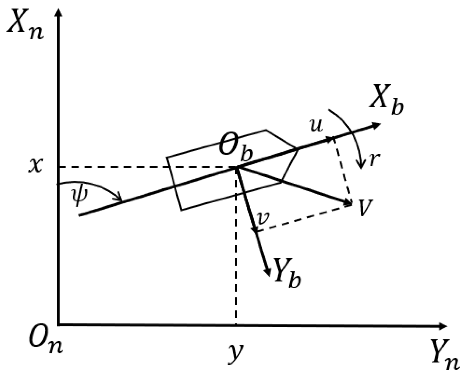
Ship has six degrees of freedom when sailing at sea. When studying the trajectory tracking problem of an underactuated ship, the motion is generally simplified to three degrees of freedom, namely surge, sway, and yaw, as shown in Figure 1. Here, X n and Y n denote the surge and sway displacements of the vessel measured in the earth-fixed (inertial) frame whose origin O n is defined at the ship’s initial deployment point. In practical applications, the triplet x , y , φ is obtained in real time from onboard navigation sensors. A GPS/GNSS receiver provides global position which is projected to local tangential coordinates, while an Inertial Navigation System or high-precision compass measures the yaw angle φ relative to true north. The origin O n is fixed by recording the GPS coordinates (latitude, longitude) at the start of the mission and converting them to the chosen local coordinate system.
The mathematical model of a three-degree-of-freedom ship is considered:
η ˙ = R ψ υ M υ ˙ + C υ υ + D υ = τ + τ w
And the mathematical model of kinematics and dynamics can be written as follows:
x ˙ = u c o s ψ v s i n ψ y ˙ = u s i n ψ + v c o s ψ ψ ˙ = r u ˙ = m 22 v r d 11 u + τ u + τ w u / m 11 v ˙ = m 11 u r d 22 v + τ w v / m 22 r ˙ = m 11 m 22 u v d 33 r + τ r + τ w r / m 33
where η = x y ψ T is the surge displacement, sway displacement, and yaw angle of the ship in the Earth-fixed coordinate frame, that is, the position vector; υ = u   v   r represents the surge velocity, sway velocity, and yaw angular velocity of the vessel in the body-fixed coordinate frame, which is the velocity vector; R ( ψ ) is the conversion matrix between the Earth-fixed coordinate frame and the body-fixed coordinate frame, satisfying R T ψ = R 1 ψ . The expression of R ( ψ ) is as follows:
R ψ = c o s ( ψ ) s i n ( ψ ) 0 s i n ( ψ ) c o s ( ψ ) 0 0 0 1
M is the ship inertia matrix:
M = m 11 0 0 0 m 22 0 0 0 m 33
C ( υ ) is the Coriolis force matrix:
C υ = 0 0 c 13 0 0 c 23 c 13 c 23 0
where c 13 = m 22 v , c 23 = m 11 u .
D is the hydrodynamic damping parameter matrix:
D = d 11 0 0 0 d 22 0 0 0 d 33
Because the underactuated ship has no lateral control forces, that is, τ v = 0 , so τ = τ u 0 τ r T , τ u is the surge force of the ship, τ r is the yawing moment of the ship; τ w = τ w u τ w v τ w r T is the external environment interference. And m 11 = m X u ˙ , m 22 = m Y v ˙ , m 33 = I Z N r ˙ , d 11 = X u , d 22 = Y v , d 33 = N r . Among them, m is the mass of the ship; I Z is the moment of inertia; hydrodynamic force derivatives X u ˙ = X / u ˙ , Y v ˙ = Y / v ˙ , N r ˙ = N / r ˙ .
Assumption 1.
The reference trajectory of the underactuated ship is smooth and has first- and second-order derivatives.
Assumption 2.
The interference of the external environment is represented by time-varying disturbances  τ w u , τ w v , τ w r  , and the upper bounds of the disturbances  τ w u * , τ w v * , τ w r *  are known.
Lemma 1
[24]. For nonlinear systems, if there is a positive definite Lyapunov function  V ( x ) : Ω 0 R and any scalar  α > 0 ,   0 < β < 1 , so that the inequality  V ˙ x α V β ( h ) holds, the system is finite-time stable, and its stabilization time  t is
t V 1 β ( 0 ) α ( 1 β )
Control objectives: Aiming at the underactuated ship mathematical model (2), under the condition that the assumption is established, the controller is designed so that the underactuated ship can track the desired trajectory within a limited time and maintain stability.

3. Control Design

The study primarily focuses on controlling the surge and steering motion of the vessel using only the propeller and rudder, without incorporating lateral control forces. Therefore, in the design of the controller, emphasis is placed on determining the appropriate surge force τ u and yawing moment τ r to indirectly regulate the lateral control force of the ship. 
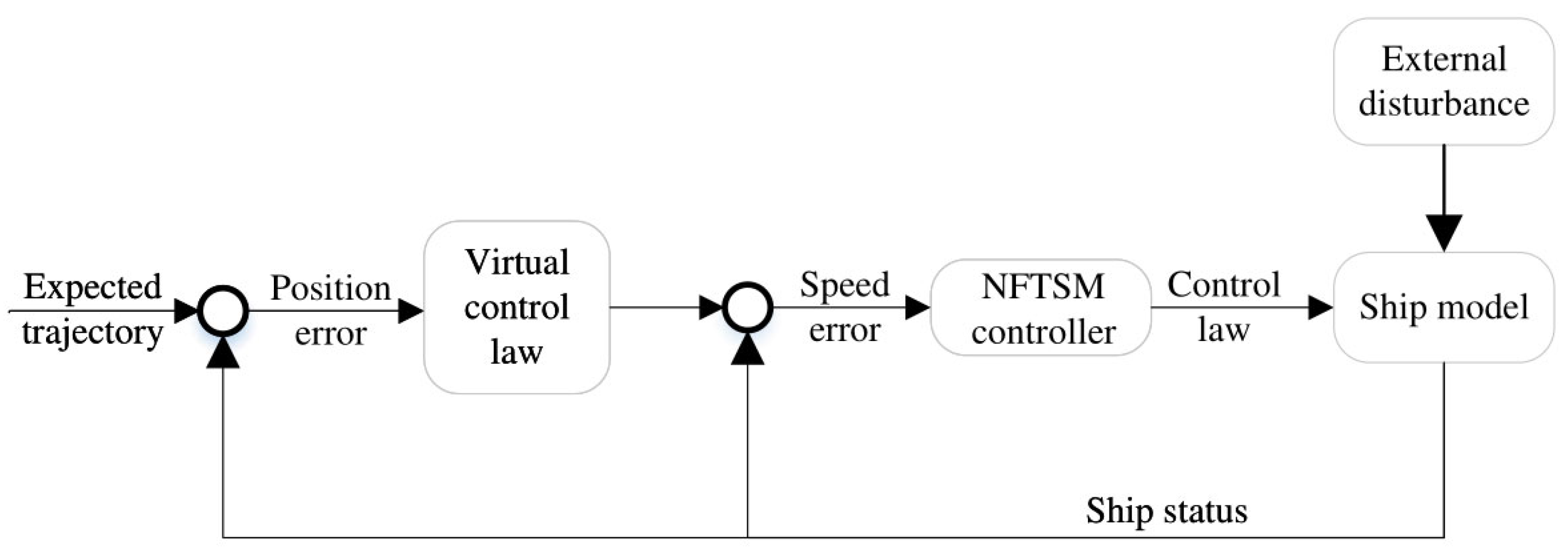
Figure 2 depicts the ship trajectory tracking and control process.
First, a virtual control law is formulated based on the position error of the ship, serving as the reference velocity that the vessel should follow. Subsequently, the error between the desired speed and the actual speed is calculated, and an NFTSMC is designed to solve for the ship’s surge force τ u and yawing moment τ r . This controller is specifically designed to eliminate singularity issues and ensure precise control performance. Ultimately, the computed control laws are applied to the underactuated ship, enabling it to accurately follow the desired trajectory even in the presence of external disturbances.

3.1. Design of Virtual Control Law

The definition of surge and sway position tracking error is as follows:
x e = x x d y e = y y d
where x d ,   y d are the surge and sway coordinates of the desired trajectory, respectively, x ,   y are the actual surge and sway coordinates of the ship, and x e ,   y e are the surge and sway position tracking errors, respectively.
The derivative of Formula (3) with respect to time t can be obtained as follows:
u v = cos ψ sin ψ sin ψ cos ψ x ˙ e + x ˙ d y ˙ e + y ˙ d
To ensure stability in trajectory tracking for the ship, the virtual control laws for surge and sway, u and v , are designed separately. Specifically, the surge virtual control law, denoted as α u , and the sway virtual control law, denoted as α v [21], are formulated.
α u α v = cos ψ sin ψ sin ψ cos ψ x ˙ d k W 1 x e y ˙ d k W 1 y e
where W = x e 2 + y e 2 + C , k > 0 ,   C > 0 . Therefore,
x ˙ e y ˙ e = cos ψ sin ψ sin ψ cos ψ u α u v α v + k W 1 x e k W 1 y e
When u = α u ,   v = α v , the formula is arranged as follows:
x ˙ e y ˙ e = k W 1 x e k W 1 y e
In order to verify the stability of the designed virtual control law, the following Lyapunov function is constructed:
V = 1 2 x e 2 + 1 2 y e 2
The derivation of Formula (8) is as follows:
V ˙ = x e x ˙ e + y e y ˙ e = k W 1 x e 2 + y e 2
From Formula (9), it can be determined that lim t V ˙ 0 . Combined with Formula (7) and applying the stability criterion, it can be concluded that the position error is asymptotically stable.
The derivation of Formula (5) is as follows:
α ˙ u α ˙ v = r α v r α u + cos ψ sin ψ sin ψ cos ψ F
where
F = x ¨ d k W 1 W 3 x e 2 x ˙ e + k W 3 x e y e y ˙ e y ¨ d k W 1 W 3 y e 2 y ˙ e + k W 3 x e y e x ˙ e
f = f 1 f 2 = cos ψ sin ψ sin ψ cos ψ F

3.2. NFTSM Controller Design

Define surge velocity error u e and sway velocity error v e as follows:
u e = u α u
v e = v α v
The following NFTSM surfaces are designed separately for u e and v e :
S 1 = u ˙ e + a u e + b u e q p , s ¯ 1 = 0   o r   s ¯ 1 0 ,   u e ε u ˙ e + k 1 u e + k 2 u e 2 s g n u e , s ¯ 1 0 ,   u e < ε
S 2 = v ˙ e + a v e + b v e q p , s ¯ 2 = 0   o r   s ¯ 2 0 ,   v e ε v ˙ e + k 1 v e + k 2 v e 2 s g n v e , s ¯ 2 0 ,   v e < ε
where s ¯ 1 = u ˙ e + a u e + b u e q / p ,   s ¯ 2 = v ˙ e + a v e + b v e q / p ,   a > 0 ,   b > 0 ,   0 < q / p < 1 ,   ε > 0 ,   k 1 > 0 ,   k 2 > 0 .
According to the NFTSM surface, the surge force τ u and the yawing moment τ r are designed as follows:
τ u = ( B ζ 1 s g n S 1 μ 1 S 1 ) / A , s ¯ 1 = 0   o r   s ¯ 1 0 ,   u ˙ e ε ( E ζ 2 s g n S 1 μ 2 S 1 ) / D , s ¯ 1 0 ,   u ˙ e < ε
τ r = ( G ζ 3 s g n S 2 μ 3 S 2 ) / F , s ¯ 2 = 0   o r   s ¯ 2 0 ,   v e ε ; ( I ζ 4 s g n S 2 μ 4 S 2 ) / H , s ¯ 2 0 ,   v e < ε .
where ζ 1 = η 1 + A ¯ τ w u * ,   ζ 2 = η 2 + D ¯ τ w u * ,   ζ 3 = η 3 + F ¯ τ w r * ,   ζ 4 = η 4 + H ¯ τ w r * ; η 1 > 0 ,   η 2 > 0 ,   η 3 > 0 , η 4 > 0 , A ¯ is the upper bound of A , that is, A A ¯ ; D ¯ is the upper bound of D , that is, D D ¯ ; F ¯ is the upper bound of F , that is, F F ¯ ; H ¯ is the upper bound of H , that is, H H ¯ . In the formula
A = m 11 a + m 11 b q p u e q p 1 d 11
B = m 11 m 22 v ˙ r + v r ˙ + m 11 a + m 11 b q p u e q p 1 d 11 m 22 v r d 11 u + m 11 τ ˙ u + τ ˙ w u + m 11 2 r ˙ α v r α ˙ v f 1 ˙ α ˙ u a + b q p u e q p 1
D = m 11 k 1 + m 11 k 2 u e s g n u e d 11
E = m 11 m 22 v ˙ r + v r ˙ + ( m 11 k 3 + m 11 k 4 u e s g n u e d 11 ) ( m 22 v r d 11 u ) + m 11 τ ˙ u + τ ˙ w u + m 11 2 r ˙ α v r α ˙ v f 1 ˙ α ˙ u k 1 + k 2 u e s g n u e
F = H = m 22 α u m 11 u
G = m 11 m 33 u ˙ r m 11 m 11 m 22 u 2 v + m 11 d 33 u r d 22 m 33 v ˙ + m 33 τ ˙ w v + m 22 α u m 11 m 22 u v d 33 r + m 22 m 33 ( r α ˙ u f 2 ˙ + ( a + b q p v e q p 1 ) v ˙ α ˙ v )
I = m 11 m 33 u ˙ r m 11 m 11 m 22 u 2 v + m 22 α u m 11 m 22 u v d 33 r + m 11 d 33 u r + m 33 τ ˙ w v + m 22 m 33 r α ˙ u f 2 ˙ + k 1 + k 2 v e s g n v e v α ˙ v
Theorem 1.
Consider the underactuated ship dynamics given in Equation (2), subject to Assumptions 1 and 2. If the virtual control laws (5)–(7) apply, NFTSM surfaces (15) and (16) are used, and the surge force   τ u   and yaw moment   τ r   is chosen, as in (17) and (18), then both the surge velocity error   u e   and yaw-rate error   v e   converge to zero in finite time. Consequently, the ship’s position   x , y  and heading  φ  track the desired trajectory within a guaranteed finite time.
Proof of Theorem
(1)
Surge force
  • when s ¯ 1 = 0   o r   s ¯ 1 0 , u e ε
The Lyapunov function is constructed as follows:
V 1 = 1 2 m 11 2 S 1 2
Deriving it and substituting (15) and (17) into (26), then
V 1 ˙ = S 1 S ˙ 1 = S 1 ( ζ 1 sgn S 1 μ 1 S 1 + A τ w u ) A τ w u S 1 ζ 1 S 1 = ( A τ w u η 1 A ¯ τ w u * ) V 1 1 / 2
According to Lemma 1, the surge velocity error can converge within a finite time under the effect of the surge force. The convergence time is defined by the following expression:
t u V 1 1 / 2 ( 0 ) A ¯ τ w u * + η 1 A τ w u
  • b.
    When s ¯ 1 0 ,   u e < ε
Construct the Lyapunov function as follows:
V 1 = 1 2 m 11 2 S 1 2
Deriving it and substituting (15) and (17) into (28), then
V 1 ˙ = S 1 S 1 ˙ = S 1 ( ζ 2 s g n S 1 μ 2 S 1 + D τ w u ) D τ w u S 1 ζ 2 S 1 = ( D τ w u η 2 D ¯ τ w u * ) V 1 1 / 2
According to Lemma 1, the surge velocity error can converge within a finite time under the effect of the surge force. The convergence time is defined by the following expression.
t u V 1 1 / 2 ( 0 ) D τ w u * + η 2 D τ w u
(2)
Yawing moment
  • When s ¯ 1 = 0   o r   s ¯ 1 0 , u e ε
construct the Lyapunov function as follows:
V 1 = 1 2 m 22 m 33 S 2 2
Deriving it and substituting (16) and (18) into (30), then
V 2 ˙ = S 2 S ˙ 2 = S 2 ( ζ 3 s g n S 2 μ 3 S 2 + F τ w r ) D τ w r S 2 ζ 3 S 2 = ( D τ w r η 3 D ¯ τ w r * ) V 2 1 / 2
According to Lemma 1, the sway velocity error can converge within a finite time under the effect of the yawing moment. The convergence time is defined by the following expression.
t r V 2 1 / 2 ( 0 ) D ¯ τ w r * + η 3 D τ w r
b. When s ¯ 1 0 , u e < ε
Construct the Lyapunov function as follows:
V 1 = 1 2 m 22 m 33 S 2 2
Deriving it and substituting (16) and (18) into (32), then
V 2 ˙ = S 2 S ˙ 2 = S 2 ( ζ 4 sgn S 2 μ 4 S 2 + H τ w r ) H τ w r S 2 ζ 4 S 2 = ( H τ w r η 4 H ¯ τ w r * ) V 2 1 / 2
According to Lemma 1, the sway velocity error can converge within a finite time under the effect of the yawing moment. The convergence time is defined by the following expression.
t r V 2 1 / 2 ( 0 ) H ¯ τ w r * + η 4 H τ w r
From the above, it can be seen that this method is more suitable for tracking the desired trajectory of the ship in a limited time. □
Theorem 2.
Consider the underactuated ship dynamics described in Equation (2), under the conditions specified by Assumptions 1 and 2. If the virtual control laws defined in Equations (5)–(7) and NFTSM surfaces (15) and (16) are employed, and the surge force  τ u  and yaw moment  τ r  are chosen as in (17) and (18), then both the surge velocity error  u e  and yaw-rate error  v e  converge to zero in finite time. The closed-loop error signals  u e ,   v e ,   s 1 ,   s 2  are all error signals of the underactuated ship tracking control closed-loop system, and are consistent and eventually bounded.
Proof of Theorem
(1)
Surge force
  • When s ¯ 1 = 0   o r   s ¯ 1 0 ,   u e ε
Construct the Lyapunov function as follows:
V 1 = 1 2 m 11 2 S 1 2
Deriving it and substituting (15) and (17) into (34), then
V 1 ˙ = S 1 S 1 ˙ = S 1 ( ζ 1 s g n S 1 μ 1 S 1 + A τ w u ) A τ w u S 1 ζ 1 S 1 η 1 S 1
  • b.
    When s ¯ 1 0 ,   u e < ε
Construct the Lyapunov function as follows:
V 1 = 1 2 m 11 2 S 1 2
Deriving it and substituting (15) and (17) into (36), then
V 1 ˙ = S 1 S 1 ˙ = S 1 ( ζ 2 s g n S 1 μ 2 S 1 + D τ w u ) D τ w u S 1 ζ 2 S 1 η 2 S 1
(2)
Yawing moment
  • When s ¯ 1 = 0 o r s ¯ 1 0 , u e ε
Construct the Lyapunov function as follows:
V 2 = 1 2 m 22 m 33 S 2 2
Deriving it and substituting (16) and (18) into (38), then
V 2 ˙ = S 2 S 2 ˙ = S 2 ( ζ 3 s g n S 2 μ 3 S 2 + F τ w r ) D τ w r S 2 ζ 3 S 2 η 3 S 2
  • b.
    When s ¯ 1 0 , u e < ε
Construct the Lyapunov function as follows:
V 2 = 1 2 m 22 m 33 S 2 2
Deriving it and substituting (16) and (18) into (40), then
V 2 ˙ = S 2 S 2 ˙ = S 2 ( ζ 4 s g n S 2 μ 4 S 2 + H τ w r ) H τ w r S 2 ζ 4 S 2 η 4 S 2
From Equations (35), (37), (39) and (41), it can be seen that V ˙ = V 1 ˙ + V 2 ˙ 0 . This indicates that all error signals in the underactuated ship trajectory tracking system are consistent and ultimately bounded. □

3.3. Yaw Angle Stability Analysis

Construct the Lyapunov function as follows:
V 3 = 1 2 m 33 r 2
Deriving Formula (42) and substituting Formula (2):
V ˙ 3 = r ( m 11 m 22 u v d 33 r + τ r + τ w r )
If d 33 r > r ( m 11 m 22 u v + τ r + τ w r ) . Then V ˙ 3 < 0 . So r is a decreasing function under the condition of d 33 r > r ( m 11 m 22 u v + τ r + τ w r ) . Therefore, τ w u , τ w r , u , v are bounded, and the yaw angular velocity r is also bounded. The certificate is completed.
The initial values of the controller parameters were determined based on a combination of theoretical guidelines and empirical tuning. Specifically, the parameters λ i were initially chosen to be sufficiently large to ensure rapid disturbance estimation while avoiding excessive noise and the gains k r 1 , k r 2 and nonlinear terms c 3 , c 4 were iteratively adjusted through simulation to achieve an optimal balance between response speed, chatter suppression, and stability. Detailed processes for selecting initial values are illustrated in the parameter sensitivity analysis provided in the simulation section.

4. Simulation

In order to verify the performance of the NFTSMC designed in this paper, this section compares the traditional SMC with the controller designed in this paper. To ensure a fair and meaningful comparison, the baseline sliding mode controller (SMC) implemented in this study adopts the same virtual control laws defined in Equations (13) and (14) as the proposed NFTSMC. The SMC controller uses a conventional linear sliding surface defined as s = e + λ e d t , and its control law is based on the sign-type exponential reaching law:
s ˙ = k s i g n   ( s )
where k > 0 is a constant gain and λ is a design parameter to ensure sliding mode convergence. This control structure is commonly used in traditional SMC implementations for trajectory tracking of underactuated ships. The only difference between SMC and NFTSMC in this study lies in the sliding surface and reaching law design NFTSMC replaces the discontinuous sign-based reaching law with a continuous, non-singular fast terminal surface, allowing finite-time convergence and improved control smoothness.
The ship model in literature [22] is selected for the comparison simulation experiment, and the ship model parameters are listed as follows:
m 11 = 1.2 × 10 5 k g , m 22 = 1.779 × 10 5 k g , m 33 = 6.36 × 10 7 k g d 11 = 2.15 × 10 4 k g / s , d 22 = 1.47 × 10 5 k g / s ,   d 33 = 8.02 × 10 6 k g / s
The interference force generated by the external environment is τ w u = 10 4 sin 0.2 t + cos 0.5 t ,   τ w v = 10 2 sin 0.1 t + cos 0.4 t , τ w r = 10 3 sin 0.5 t + cos 0.3 t . Regarding the tracking research of reference trajectories for straight lines and curves, first set the desired trajectory for the straight line as x d = 10 t , y d = t . The initial state of the ship is x ( 0 ) , y ( 0 ) , ψ ( 0 ) , u ( 0 ) , v ( 0 ) , r ( 0 ) = 40 , 20 , 0 , 0 , 0 , 0 ; parameters a = 1 , b = 1 , q = 21 , p = 27 ,   ε = 0.9 ,   k = 1 , k 1 = 1 ,   k 2 = 1 ,   C = 5 ,   η 1 = η 2 = η 3 = η 4 = 1 × 10 3 , μ = 1000 ,   τ w u * = 1 × 10 5 ,   τ w v * = 1 × 10 3 , τ w r * = 1 × 10 3 .
In the above values, the initial choice of the fractional power q / p as 21/27 was guided by general recommendations from existing literature and extensive simulation experiments. This ratio not only satisfies the finite-time convergence conditions specified in Lemma 1 but also demonstrated optimal convergence speed and robustness in practical control performance through multiple simulations. Other numerical combinations were tested, but the 21/27 ratio provided the best overall performance. The simulation results are shown in Figure 3, Figure 4, Figure 5, Figure 6 and Figure 7.
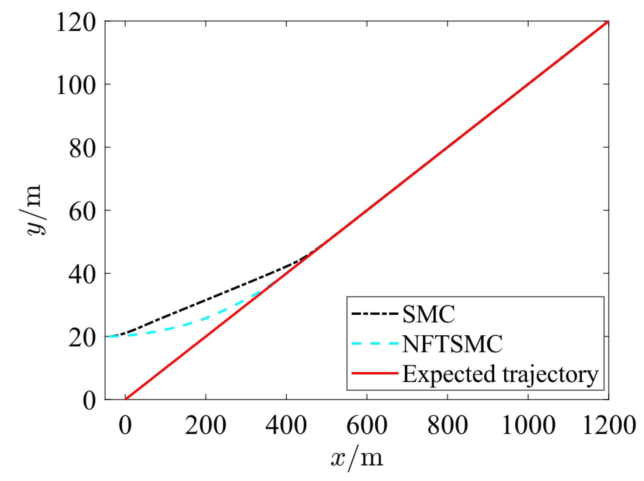
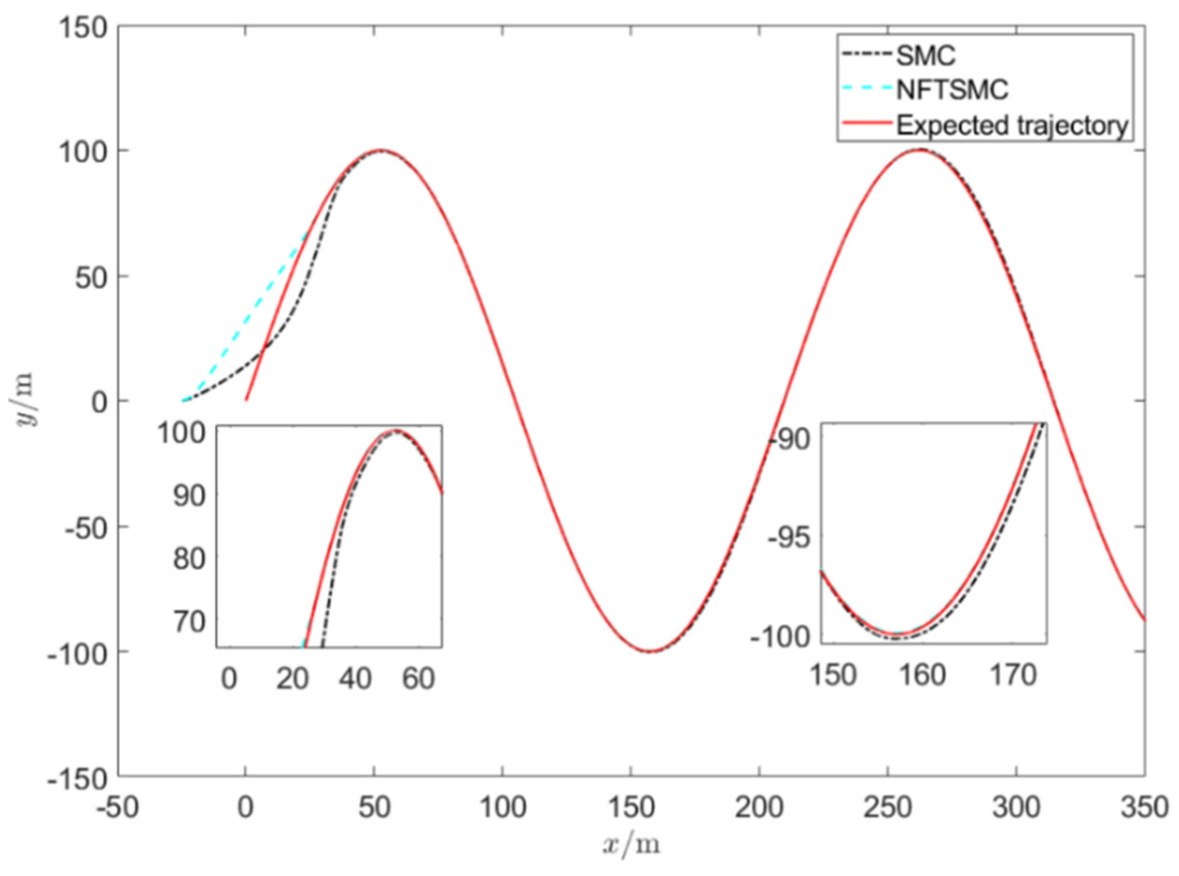
Figure 3 shows the results of traditional SMC and NFTSM controller designed in this paper for ship trajectory tracking. As shown in Figure 3, the proposed NFTSM controller enables the underactuated ship to track the desired trajectory more rapidly and maintain stable tracking even in the presence of disturbances, which means that the NFTSM controller is effective and superior.
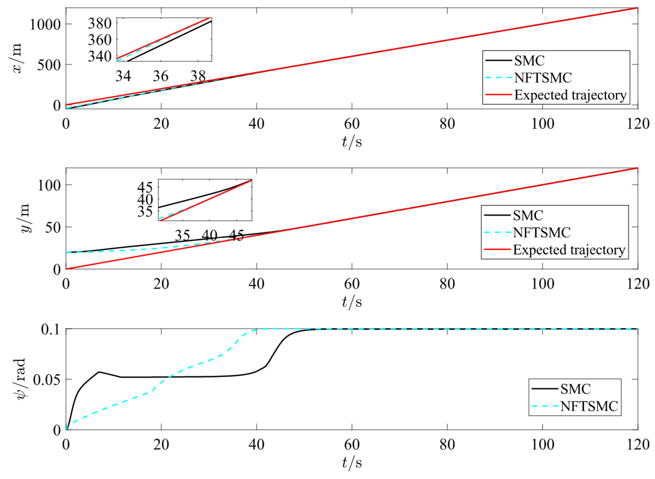
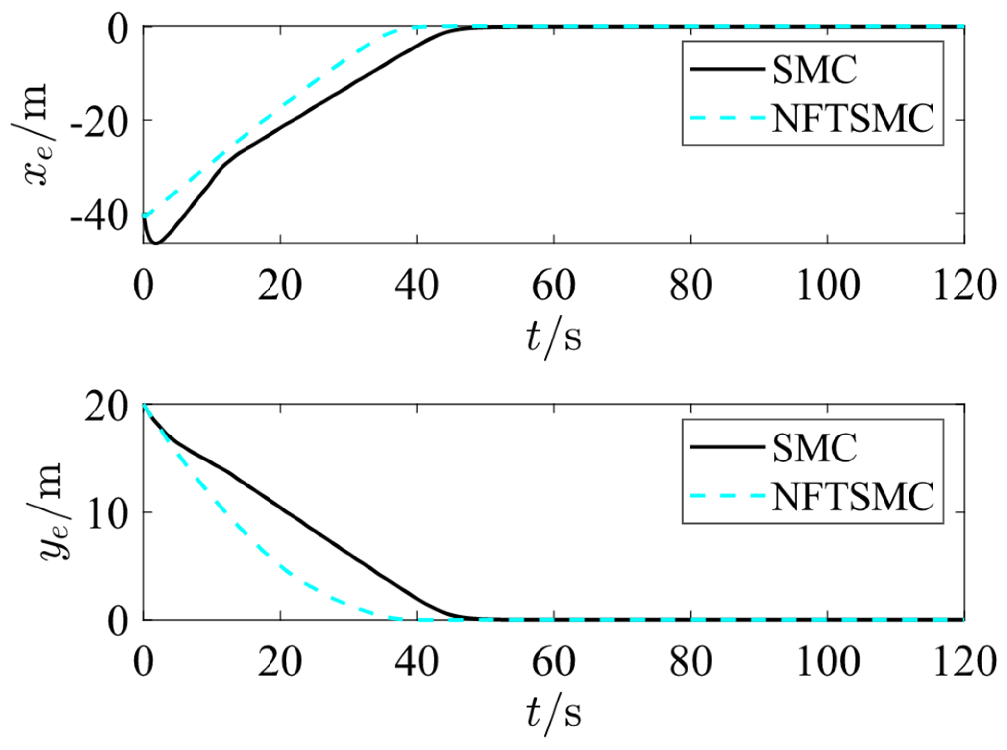
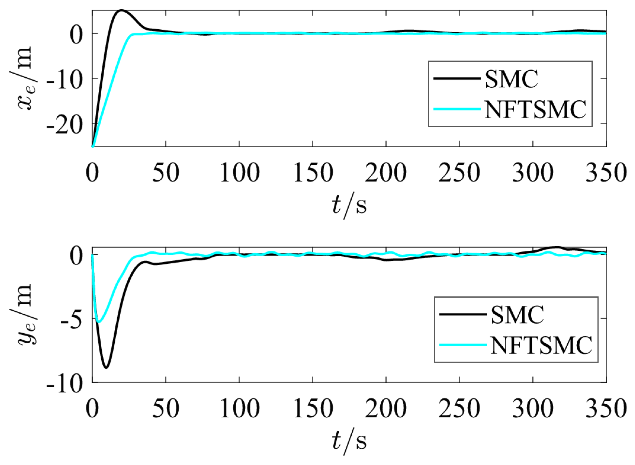
 Figure 4 and Figure 5 show that the ship trajectory error under NFTSM control tends to zero within 40 s, making it faster and smoother than the traditional SMC. 
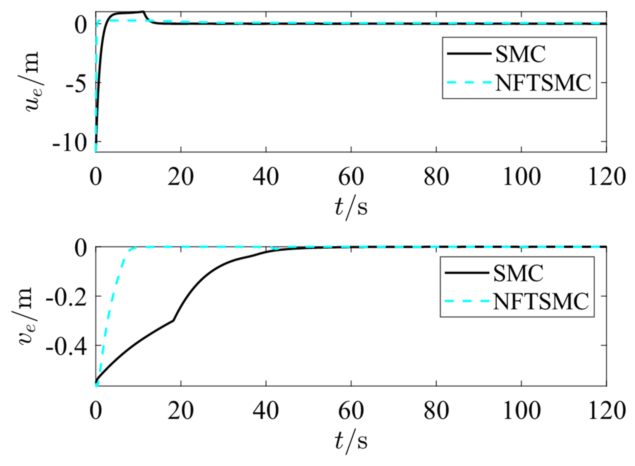
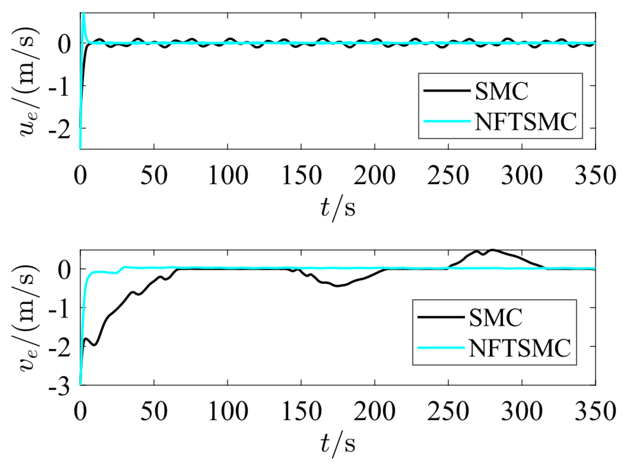
Figure 6 shows the variation curves of surge speed error u e and sway speed error v e of the underactuated ship during the control process by two controllers. It can be seen that using NFTSM controller can make the ship converge the error faster. 
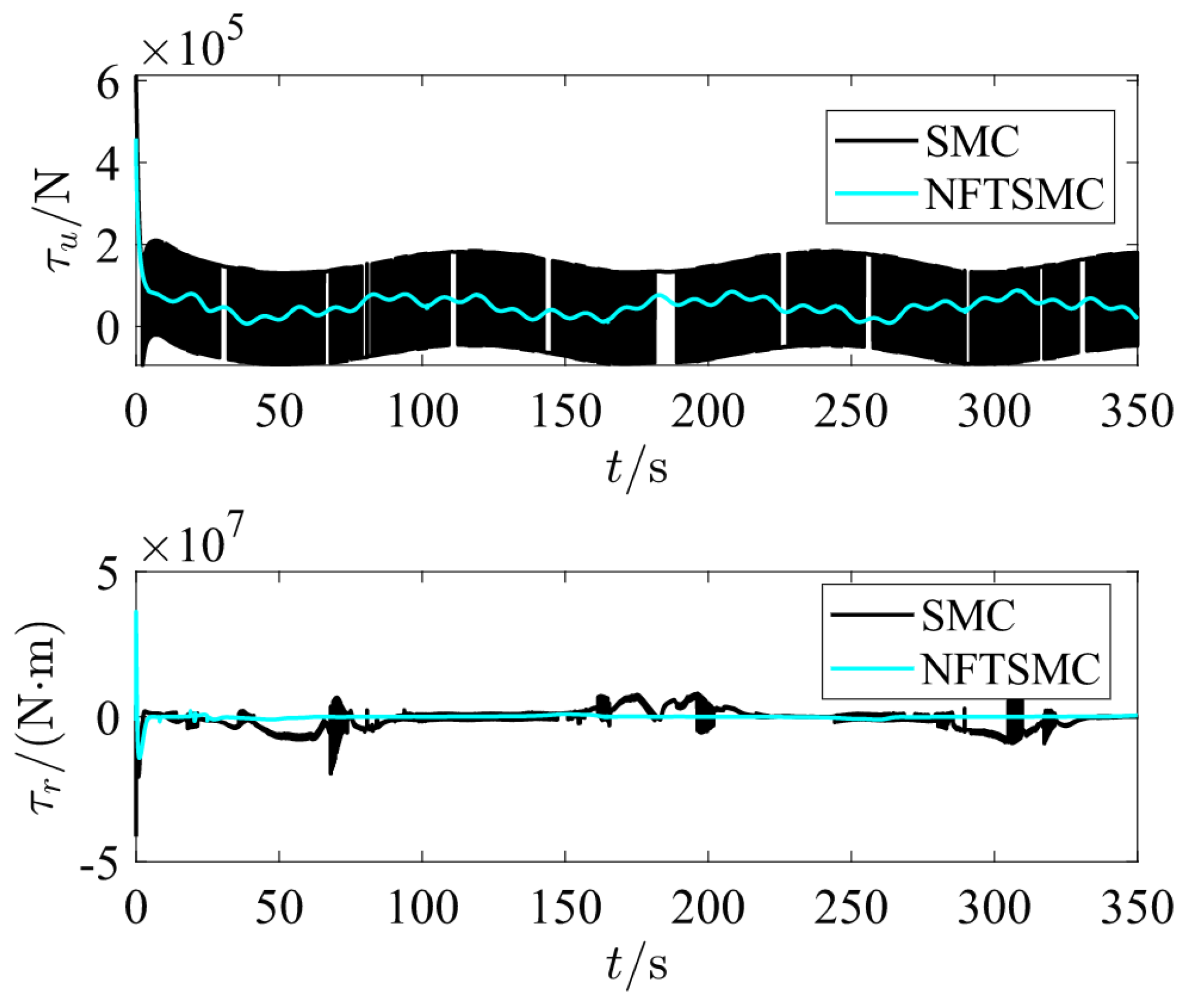
Figure 7 shows the curves of surge force τ u and yawing moment τ r of the underactuated ship. It can be observed that the NFTSM controller effectively suppresses oscillations, thereby enhancing navigational safety and efficiency while also reducing actuator wear and tear.
The set curve reference trajectory is x d = t , y d = 100 s i n ( 0.03 t ) . The initial state of the ship is set to [ x 0 , y 0 , ψ 0 , u 0 , v ( 0 ) , r ( 0 ) ] = 25 , 0 , 0 , 0 , 0 , 0.5 . The control parameters remain unchanged. The simulation results are shown in Figure 8, Figure 9, Figure 10, Figure 11 and Figure 12. As shown in
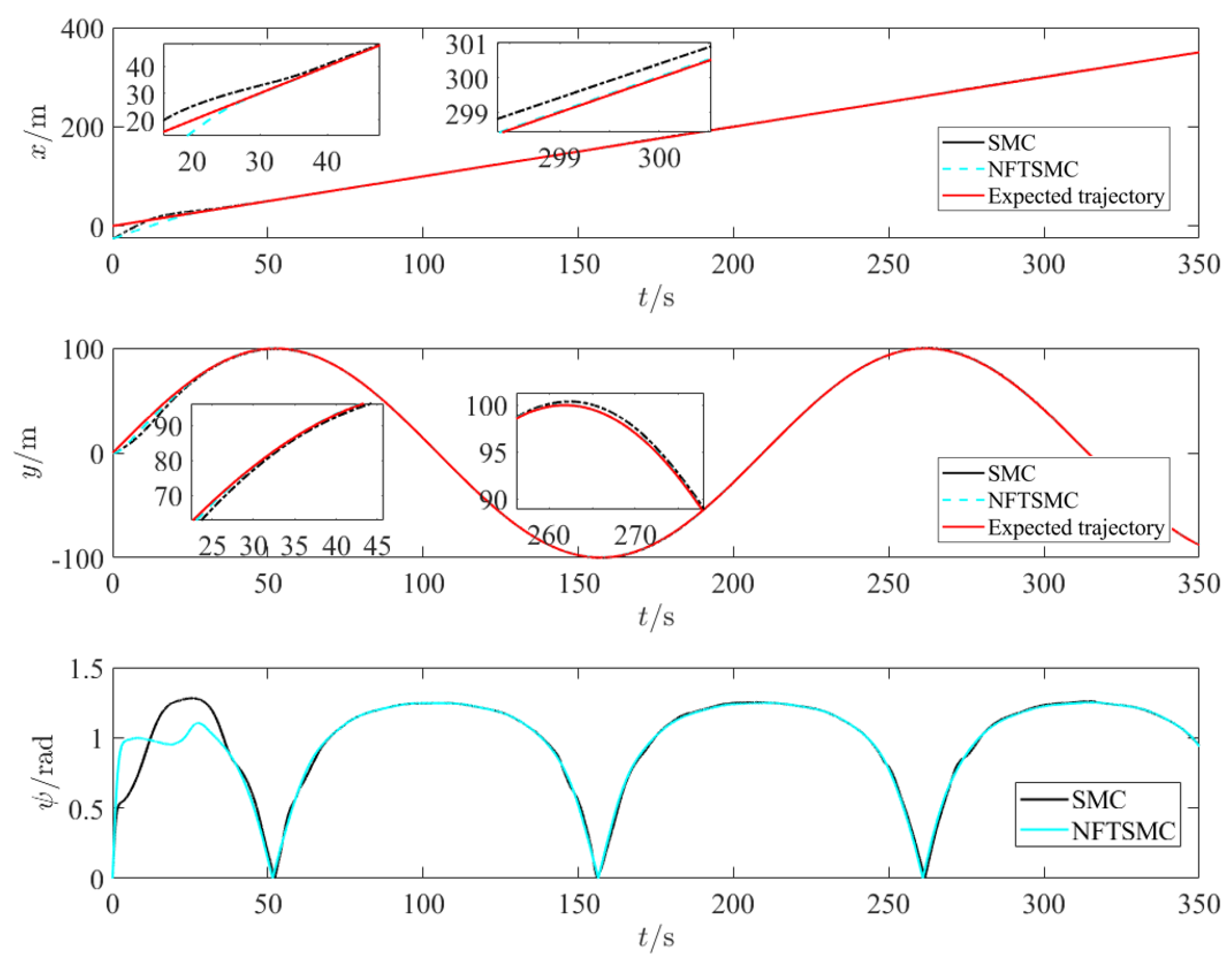
 Figure 8, Figure 9 and Figure 10, in the presence of known disturbances, the ship demonstrates excellent tracking performance for the curved reference trajectory and outperforms the traditional sliding mode controller (SMC). In particular, the traditional SMC exhibits inferior turning performance compared to the NFTSM controller. Figure 11 shows the variations in the surge speed error u e and sway speed error v e of the underactuated ship during the control process using both algorithms. It can be observed that using the NFTSM controller can make the ship converge faster and the error changes smoothly, which is more in line with the actual navigation of the ship. Figure 12 shows the curves of the surge force τ u and yawing moment τ r of the underactuated ship. It can be seen that the NFTSM controller effectively reduces the generation of oscillations, improves the safety and navigation efficiency of the ship, and reduces the wear and tear of the actuators.
In summary, the proposed NFTSM controller for underactuated ships enables rapid and stable trajectory tracking, even in the presence of environmental disturbances, within a finite time. Furthermore, it effectively suppresses oscillations, which is of critical importance for enhancing the safety, navigational efficiency, reliability, and operational comfort of marine vessels.

5. Conclusions

This paper proposes an NFTSMC method to address the issues of non-singularity and slow convergence in traditional terminal sliding mode control, specifically applied to the trajectory tracking of underactuated ships. A virtual control law is first designed based on the position error of the vessel, which determines the desired speed during the tracking process. The speed error is then computed, and the ship’s surge force and yawing moment are derived using the NFTSMC controller. Leveraging Lyapunov’s stability principle and finite-time stability theory, it is demonstrated that the system converges within a finite time, ensuring both stability and robustness. Simulation results confirm the proposed controller’s strong resilience against environmental disturbances, such as wind, waves, and currents. The proposed controller exhibits outstanding trajectory tracking performance, enabling the vessel to swiftly and accurately follow reference paths. These findings underscore the controller’s potential to enhance sustainable maritime operations by delivering precise navigation control while simultaneously reducing energy consumption and minimizing environmental impact.
While the study assumes known external disturbances, future research will incorporate the effects of unknown disturbances to further enhance the controller’s robustness and adaptability. This approach holds significant promise for sustainable maritime navigation, contributing to the advancement of more efficient and environmentally friendly ship control systems.

Author Contributions

Conceptualization, M.Z. and Q.C.; methodology, Y.S.; software, Y.S. and G.C.; validation, M.Z., Q.C., Y.S. and G.C.; formal analysis, Q.C. and G.C.; investigation, G.C.; resources, M.Z. and G.C.; data curation, Q.C.; writing—original draft preparation, Q.C. and Y.S.; writing—review and editing, M.Z. and G.C.; visualization, M.Z.; supervision, G.C.; project administration, M.Z.; funding acquisition, G.C. All authors have read and agreed to the published version of the manuscript.

Funding

This study was supported by the National Natural Science Foundation of China (Shenhua Yang, No. 52371369), Xiamen Municipal Natural Science Foundation Upper-level Project (Weijun Wang, No. 3502Z202373038), National Key Research and Development Program of China (Weijun Wang, No. 2021YFB390150), Fujian Provincial Natural Science Program (Hongbo Sun, No. 2022J01323, 2023J01325, 2023I0019), Fujian Provincial Science and Technology Program (Weijun Wang, No. 3502ZCQXT2021007), Fujian Provincial Funds for Promoting High-quality Development of Marine and Fishery Industry (Jinhai Chen, No. FJHYF-ZH-2023-10), and Natural Science Foundation of Jimei University (Weijun Wang, No. ZQ2023015).

Institutional Review Board Statement

Not applicable.

Informed Consent Statement

Not applicable.

Data Availability Statement

The data presented in this study are available on request from the corresponding author.

Conflicts of Interest

The authors declare no conflicts of interest.

References

  1. Wang, S.S. Research on Robust Control for Trajectory Tracking and Area-Keeping of Underactuated Surface Vessel. Ph.D. Thesis, Harbin Engineering University, Harbin, China, 2020. [Google Scholar]
  2. Hernandez-Alvarado, R.; Garcia-Valdovinos, L.G.; Salgado-Jimenez, T.; Gomez-Espinosa, A.; Navarro, F.F. Self-tuned PID Control based on Backpropagation Neural Networks for Underwater Vehicles. In Proceedings of the MTS/IEEE Oceans Conference, Monterey, CA, USA, 19–23 September 2016. [Google Scholar]
  3. Khooban, M.H.; Vafamand, N.; Dragicevic, T.; Blaabjerg, F. Polynomial fuzzy model-based approach for underactuated surface vessels. IET Control Theory Appl. 2018, 12, 914–921. [Google Scholar] [CrossRef]
  4. Haseltalab, A.; Garofano, V.; van Pampus, M.; Negenborn, R.R. Model Predictive Trajectory Tracking Control and Thrust Allocation for Autonomous Vessels. In Proceedings of the 21st IFAC World Congress on Automatic Control—Meeting Societal Challenges, Berlin, Germany, 11–17 July 2020. [Google Scholar]
  5. Xie, J.L.; Shi, W.F.; Lan, Y.; Zhuo, J.B. Research on Sliding Mode Control of Ship Electric Propulsion Based on Power Exponent Reaching Law. Comput. Simul. 2022, 39, 279–283. [Google Scholar]
  6. Yi, G.; Liu, Z.; Zhang, J.Q.; Dong, J. A USV Heading Tracking Control Method Based on Improved Terminal Sliding Mode Control. Electron. Opt. Control. 2020, 27, 12–16. [Google Scholar]
  7. Zhang, G.G.; Yang, C. The research of AUV tracking control based on prescribed performance control combined with terminal sliding mode. Ship Sci. Technol. 2020, 42, 92–96. [Google Scholar]
  8. Guan, H.B.; Ai, J.Y. Application of global fast terminal sliding mode control in underactuated unmanned ship stabilization. J. Guangxi Univ. Nat. Sci. Ed. 2018, 43, 2172–2183. [Google Scholar]
  9. Wang, Y.Q.; Li, T.S. Finite-time trajectory tracking control of under-actuated surface vessel. J. Harbin Eng. Univ. 2017, 38, 684–689. (In Chinese) [Google Scholar]
  10. Xu, D.; Liu, Z.; Zhou, X.; Yang, L.; Huang, L. Trajectory Tracking of Underactuated Unmanned Surface Vessels: Non-Singular Terminal Sliding Control with Nonlinear Disturbance Observer. Appl. Sci. 2022, 12, 3004. [Google Scholar] [CrossRef]
  11. Lu, K.; Xia, Y. Adaptive attitude tracking control for rigid spacecraft with finite-time convergence. Automatica 2013, 49, 3591–3599. [Google Scholar] [CrossRef]
  12. Zhao, Z.H.; Xiao, L.; Jiang, B.; Cao, D. Fast nonsingular terminal sliding mode trajectory tracking control of a quadrotor UAV based on extended state observers. Control Decis. 2022, 37, 2201–2210. [Google Scholar]
  13. Wang, J.X.; Yan, X.D.; Xv, J.M. Nonsingular fast terminal-sliding-mode control for flexible manipulator system based on disturbance and friction compensation. Control Theory Appl. 2023, 40, 1199–1207. [Google Scholar]
  14. Gao, Y.X.; Hou, Y.L.; Gao, Q.; Hou, R. Compound Control Method of ADRC and FNTSM for Airborne Object Tracking System. Acta Armamentarii 2023, 44, 1071. [Google Scholar]
  15. Chen, Z.S.; Wang, X.S.; Cheng, Y.H. Continuous non-singular fast terminal sliding mode control of robotic manipulators considering disturbance and input saturation. Control Decis. 2020, 37, 903–912. [Google Scholar]
  16. Sha, L.; Wang, S.B.; Liu, Y.J. Nonsingular fast terminal sliding mode control based on extended state observer for two mass systems. Control Decis. 2023, 38, 850–856. [Google Scholar]
  17. Zhu, Q.X.; Huang, X.; Zhu, Y.H. Non-singular terminal sliding mode control of permanent magent synchronous motor based on new reaching law. Mach. Tool Hydraul. 2022, 50, 148–152. [Google Scholar]
  18. Shi, H.; Gao, W.; Jiang, X.; Su, C.; Li, P. Two-dimensional model-free Q-leaming-based output feedback fault-tolerant control for batch processes. Comput. Chem. Eng. 2024, 182, 108583. [Google Scholar] [CrossRef]
  19. Liang, X.; Yan, Y.; Wang, W.; Su, T.; He, G.; Li, G.; Hou, Z.G. Adaptive Human-Robot Interaction Torque Estimation With High Accuracy and Strong Tracking Ability for a Lower Limb Rehabilitation Robot. IEEE/ASME Trans. Mechatron. 2024, 29, 4814–4825. [Google Scholar] [CrossRef]
  20. Wang, X.; Liu, C.; Zhang, Y. Fixed-time adaptive trajectory tracking control for underactuated USVs under input saturation. IEEE Trans. Ind. Electron. 2023, 70, 5580–5590. [Google Scholar]
  21. Yang, S.; He, Z.; Duan, Y. Fast terminal sliding mode control of underactuated marine vessels with adaptive disturbance observer. Ocean. Eng. 2022, 257, 111548. [Google Scholar]
  22. Zhou, Q.; Ren, W.; Wu, Y. Prescribed performance-based nonsingular control for ship maneuvering with external disturbances. ISA Trans. 2023, 134, 57–67. [Google Scholar]
  23. Zhu, Q.D.; Yu, R.D.; Xia, G.H.; Liu, Z.L. Sliding-mode robust tracking control for underactuated surface vessels with parameter uncertainties and external disturbances. Control Theory Appl. 2012, 29, 959–964. [Google Scholar]
  24. Do, K.D.; Jiang, Z.P.; Pan, J. Robust adaptive path following of underactuated ships. In Proceedings of the 41st IEEE Conference on Decision and Control, Las Vegas, NV, USA, 10–13 December 2002. [Google Scholar]
Figure 1. The earth-fixed and body-fixed coordinate frame of vessel surface motion.
Sustainability 17 05866 g001
Figure 2. Trajectory tracking control flowchart.
Sustainability 17 05866 g002
Figure 3. Straight-line trajectory tracking curve.
Sustainability 17 05866 g003
Figure 4. The position tracking of straight-line trajectory and yaw angle.
Sustainability 17 05866 g004
Figure 5. Surge and sway position error curves of the straight-line trajectory.
Sustainability 17 05866 g005
Figure 6. Surge and sway speed error curves of the straight-line trajectory.
Sustainability 17 05866 g006
Figure 7. The controller output of the straight-line trajectory.
Sustainability 17 05866 g007
Figure 8. Curved trajectory tracking curve.
Sustainability 17 05866 g008
Figure 9. The position tracking of curved trajectory and yaw angle.
Sustainability 17 05866 g009
Figure 10. Surge and sway position error curves of the curved trajectory.
Sustainability 17 05866 g010
Figure 11. Surge and sway speed error curves of the curved trajectory.
Sustainability 17 05866 g011
Figure 12. The controller output of curved trajectory.
Sustainability 17 05866 g012
Disclaimer/Publisher’s Note: The statements, opinions and data contained in all publications are solely those of the individual author(s) and contributor(s) and not of MDPI and/or the editor(s). MDPI and/or the editor(s) disclaim responsibility for any injury to people or property resulting from any ideas, methods, instructions or products referred to in the content.

