
Simulation of a Hybrid Propulsion System on Tugboats Operating in the Strait of Istanbul


Abstract
1. Introduction
2. Literature Review
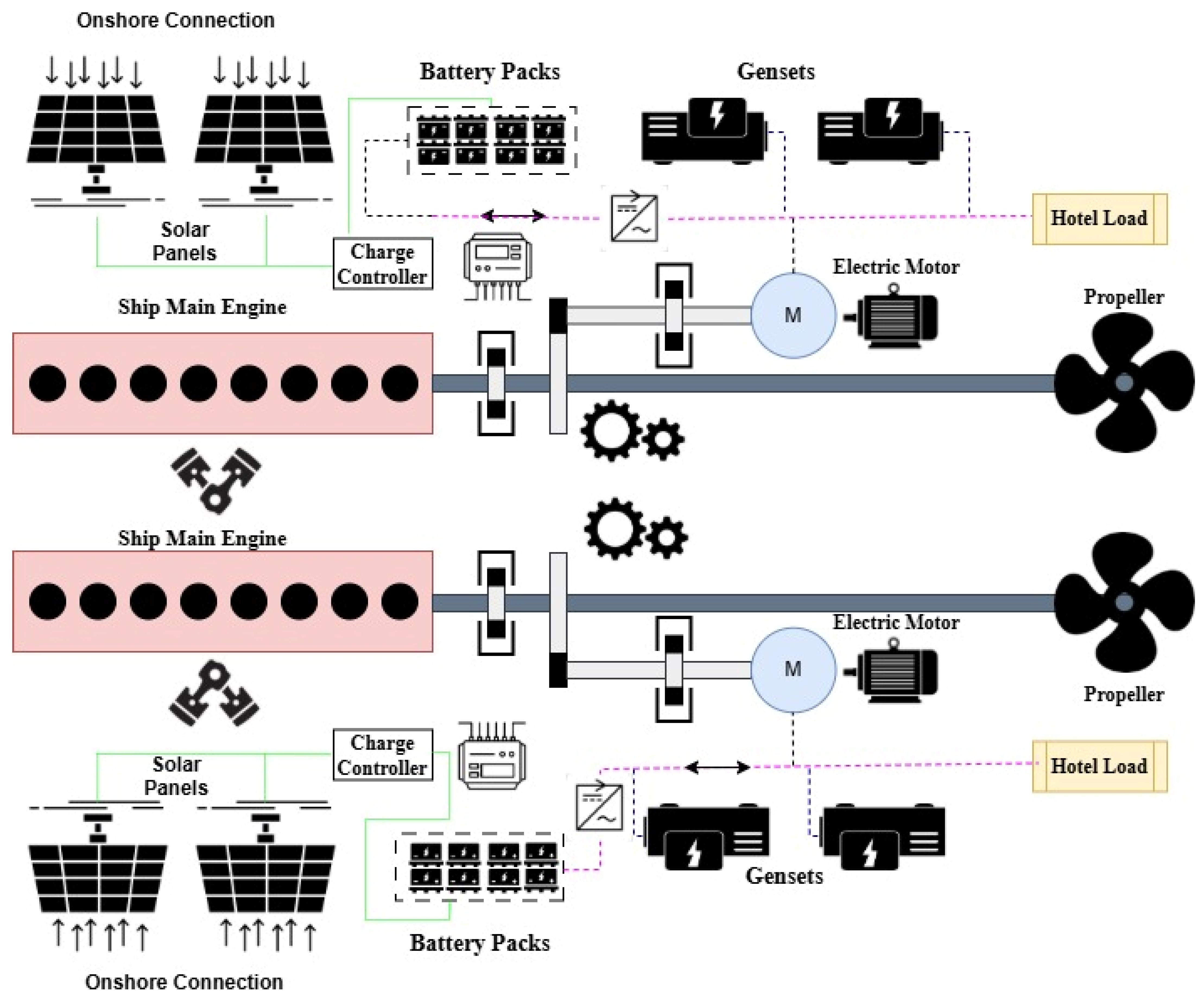
3. Materials and Methods
- ○
- The low load was defined as the utilisation of less than 20% of the power output of the main engine [53].
- ○
- Of the battery’s energy, 80% was used in the analysis for safety.
- ○
- Batteries were only charged on land, and they were not charged during operation.
- ○
- The second main engine load profile of Tugboat I was assumed to be the same as the first one.
- ○
- Transmission efficiencies of auxiliary equipment were taken as 95% unless stated otherwise.
- ○
- The onshore facility is assumed to harness solar energy for 8 h each day [54].
- ○
- Weight and volume increases of 1% were allowed in the calculation of limited fuel efficiency. However, there was no limitation for the total fuel efficiency in terms of weight and volume.
- ○
- The propeller types, sizes, and efficiencies of the tugboats remained unchanged following the installation of the HPS.
- ○
- The weather and sea conditions during data collection remained consistent throughout the installation and analysis of the HPS.
4. Results and Discussion
5. Conclusions
- HPS is well-suited for tugboats engaged in towing and pushing operations, as their main engines often operate at low loads for extended periods prior to vessel engagement, allowing for significant fuel consumption savings.
- Fuel consumption savings are comparatively lower for tugboats performing strait-crossing operations, since their main engines typically operate at optimal load levels, reducing the potential benefit of HPS integration.
- Installing long-range HPS using current technologies significantly increases weight and volume, making LiFePO4 batteries a more suitable choice than Pb–Ac types due to their higher energy density.
- Fuel consumption savings decrease when volume and weight limitations are applied, particularly in long-range and low-load operations. However, increasing the 1% allowance for added weight and volume could enhance fuel consumption savings.
- Larger electric motors can yield higher fuel consumption savings, but their selection must balance cost and operational functionality to ensure practical implementation.
- Land-based solar panel charging systems are currently more viable than onboard installations, given the limited space on tugboats. Onboard solar integration requires careful planning to maintain operational efficiency.
- The broader adoption of HPS is currently limited by technological maturity and insufficient incentives. However, regulatory developments such as carbon taxation and the expansion of emission control areas are expected to drive wider implementation across the maritime sector.
Author Contributions
Funding
Institutional Review Board Statement
Informed Consent Statement
Data Availability Statement
Acknowledgments
Conflicts of Interest
References
- United Nations For a Livable Climate: Net-Zero Commitments Must Be Backed by Credible Action. Available online: https://www.un.org/en/climatechange/net-zero-coalition (accessed on 10 June 2025).
- UNCTAD Review of Maritime Transport—Navigating Maritime Checkpoints. Available online: https://unctad.org/system/files/official-document/rmt2024_en.pdf (accessed on 20 May 2025).
- IMO. IMO’s Work to Cut GHG Emissions from Ships. Available online: https://www.imo.org/en/MediaCentre/HotTopics/Pages/Cutting-GHG-emissions.aspx (accessed on 10 June 2025).
- Ammar, N.R.; Almas, M.; Nahas, Q. Economic Analysis and the EEXI Reduction Potential of Parallel Hybrid Dual-Fuel Engine Fuel Cell Propulsion Systems for LNG Carriers. Pol. Marit. Res. 2023, 30, 59–70. [Google Scholar] [CrossRef]
- Tadros, M.; Ventura, M.; Guedes Soares, C. Review of the Decision Support Methods Used in Optimizing Ship Hulls towards Improving Energy Efficiency. J. Mar. Sci. Eng. 2023, 11, 835. [Google Scholar] [CrossRef]
- Inal, O.B.; Charpentier, J.-F.; Deniz, C. Hybrid Power and Propulsion Systems for Ships: Current Status and Future Challenges. Renew. Sustain. Energy Rev. 2022, 156, 111965. [Google Scholar] [CrossRef]
- Chin, C.S.; Tan, Y.-J.; Kumar, M.V. Study of Hybrid Propulsion Systems for Lower Emissions and Fuel Saving on Merchant Ship during Voyage. J. Mar. Sci. Eng. 2022, 10, 393. [Google Scholar] [CrossRef]
- MAN. MAN HyProp ECO—Fuel-Efficient Hybrid Propulsion System. Available online: https://man-es.com/docs/default-source/document-sync/man-hyprop-eco-eng.pdf?sfvrsn=9790dc3e (accessed on 10 June 2025).
- Zhao, T.; Xiang, D.; Zheng, Y. Control Strategy to Start a Shaft Generator System Employing DFIM under Power Take Me Home Mode. CPSS Trans. Power Electron. Appl. 2019, 4, 119–127. [Google Scholar] [CrossRef]
- ZF Hybrid Propulsion Technology. Available online: https://www.zf.com/public/org/Brochure_Hybrid-propulsion-technology_72413.pdf (accessed on 10 June 2025).
- He, Y.; Fan, A.; Wang, Z.; Liu, Y.; Mao, W. Two-Phase Energy Efficiency Optimisation for Ships Using Parallel Hybrid Electric Propulsion System. Ocean Eng. 2021, 238, 109733. [Google Scholar] [CrossRef]
- Kolodziejski, M.; Michalska-Pozoga, I. Battery Energy Storage Systems in Ships’ Hybrid/Electric Propulsion Systems. Energies 2023, 16, 1122. [Google Scholar] [CrossRef]
- Acomi, N.; Stanca, C.; Raicu, G.; Surugiu, G.; Popa, E.M. Advantages and Disadvantages of Using Electric Tugboats: A Systematic Review. J. Marit. Sci. 2025, 13, 59–70. [Google Scholar] [CrossRef]
- Bui, T.M.N.; Dinh, T.Q.; Marco, J.; Watts, C. An Energy Management Strategy for DC Hybrid Electric Propulsion System of Marine Vessels. In Proceedings of the 2018 5th International Conference on Control, Decision and Information Technologies (CoDIT), Thessaloniki, Greece, 10–13 April 2018; pp. 80–85. [Google Scholar]
- Pham, V.V.; Hoang, A.T. Analyzing and Selecting the Typical Propulsion Systems for Ocean Supply Vessels. In Proceedings of the 2020 6th International Conference on Advanced Computing and Communication Systems (ICACCS), Coimbatore, India, 6–7 March 2020; pp. 1349–1357. [Google Scholar]
- Chai, M.; Bonthapalle, D.R.; Sobrayen, L.; Panda, S.K.; Wu, D.; Chen, X. Alternating Current and Direct Current-Based Electrical Systems for Marine Vessels with Electric Propulsion Drives. Appl. Energy 2018, 231, 747–756. [Google Scholar] [CrossRef]
- Jeong, B.; Oguz, E.; Wang, H.; Zhou, P. Multi-Criteria Decision-Making for Marine Propulsion: Hybrid, Diesel Electric and Diesel Mechanical Systems from Cost-Environment-Risk Perspectives. Appl. Energy 2018, 230, 1065–1081. [Google Scholar] [CrossRef]
- Altosole, M.; Campora, U.; Vigna, V. Energy Efficiency Analysis of a Flexible Marine Hybrid Propulsion System. In Proceedings of the 2020 International Symposium on Power Electronics, Electrical Drives, Automation and Motion (SPEEDAM), Sorrento, Italy, 24–26 June 2020; pp. 436–441. [Google Scholar]
- Yuksel, O.; Pamik, M.; Bayraktar, M. The Assessment of Alternative Fuel and Engine Power Limitation Utilisation in Hybrid Marine Propulsion Systems Regarding Energy Efficiency Metrics. J. Mar. Eng. Technol. 2025, 1–15. [Google Scholar] [CrossRef]
- Oo, T.Z.; Ren, Y.; Kong, A.W.-K.; Wang, Y.; Liu, X. Power System Design Optimization for a Ferry Using Hybrid-Shaft Generators. IEEE Trans. Power Syst. 2022, 37, 2869–2880. [Google Scholar] [CrossRef]
- Ruggiero, V.; Morace, F. Innovative Use of Hybrid Propulsion System in Fast Passenger Ferries over 300 Passengers and 20 Knots. In HSMV 2020; IOS Press: Amsterdam, The Netherlands, 2020; pp. 207–215. [Google Scholar]
- Jeong, B.; Wang, H.; Oguz, E.; Zhou, P. An Effective Framework for Life Cycle and Cost Assessment for Marine Vessels Aiming to Select Optimal Propulsion Systems. J. Clean. Prod. 2018, 187, 111–130. [Google Scholar] [CrossRef]
- Alami, A.H.; Jansson, K.; Alashkar, A.; Mahmoud, M.; Yasin, A.; Khuri, S. A Techno-Economic-Environmental Investigation of Replacing Diesel Engines with Pneumatic Motors for Ferry Boats. Energy Convers. Manag. 2025, 327, 119613. [Google Scholar] [CrossRef]
- Maloberti, L.; Zaccone, R. An Environmentally Sustainable Energy Management Strategy for Marine Hybrid Propulsion. Energy 2025, 316, 134517. [Google Scholar] [CrossRef]
- Kim, S.; Jeon, H.; Park, C.; Kim, J. Lifecycle Environmental Benefits with a Hybrid Electric Propulsion System Using a Control Algorithm for Fishing Boats in Korea. J. Mar. Sci. Eng. 2022, 10, 1202. [Google Scholar] [CrossRef]
- Vasilikis, N.I.; Geertsma, R.D.; Visser, K. Operational Data-Driven Energy Performance Assessment of Ships: The Case Study of a Naval Vessel with Hybrid Propulsion. J. Mar. Eng. Technol. 2023, 22, 84–100. [Google Scholar] [CrossRef]
- Maydison; Zhang, H.; Han, N.; Oh, D.; Jang, J. Optimized Diesel–Battery Hybrid Electric Propulsion System for Fast Patrol Boats with Global Warming Potential Reduction. J. Mar. Sci. Eng. 2025, 13, 1071. [Google Scholar] [CrossRef]
- Barelli, L.; Bidini, G.; Gallorini, F.; Iantorno, F.; Pane, N.; Ottaviano, P.A.; Trombetti, L. Dynamic Modeling of a Hybrid Propulsion System for Tourist Boat. Energies 2018, 11, 2592. [Google Scholar] [CrossRef]
- Li, L.; Yi, P.; Wu, S.; Huang, S.; Li, T. Analysis of Impact of Control Strategies on Integrated Electric Propulsion System Performance During Icebreaking Process. J. Mar. Sci. Eng. 2024, 12, 1888. [Google Scholar] [CrossRef]
- Di Bernardo, R.; Di Cecca, B.; Coppola, T.; Spazzafumo, G.; Speranza, D. Preliminary Design of a 75 m Mega Yacht with Diesel—Electric Hybrid Propulsion Powered with Hydrogen FCs. Int. J. Hydrogen Energy 2025, 137, 917–924. [Google Scholar] [CrossRef]
- Capasso, C.; Veneri, O.; Notti, E.; Sala, A.; Figari, M.; Martelli, M. Preliminary Design of the Hybrid Propulsion Architecture for the Research Vessel “G. Dallaporta”. In Proceedings of the 2016 International Conference on Electrical Systems for Aircraft, Railway, Ship Propulsion and Road Vehicles & International Transportation Electrification Conference (ESARS-ITEC), Toulouse, France, 2–4 November 2016; pp. 1–6. [Google Scholar]
- Martinić-Cezar, S.; Jurić, Z.; Assani, N.; Račić, N. Controlling Engine Load Distribution in LNG Ship Propulsion Systems to Optimize Gas Emissions and Fuel Consumption. Energies 2025, 18, 485. [Google Scholar] [CrossRef]
- Sun, X.; Yao, C.; Song, E.; Yang, Q.; Yang, X. Optimal Control of Transient Processes in Marine Hybrid Propulsion Systems: Modeling, Optimization and Performance Enhancement. Appl. Energy 2022, 321, 119404. [Google Scholar] [CrossRef]
- Damian, S.E.; Wong, L.A.; Shareef, H.; Ramachandaramurthy, V.K.; Chan, C.K.; Moh, T.S.Y.; Tiong, M.C. Review on the Challenges of Hybrid Propulsion System in Marine Transport System. J. Energy Storage 2022, 56, 105983. [Google Scholar] [CrossRef]
- Bayraktar, M.; Cerit, G.A. An Assessment on the Efficient Use of Hybrid Propulsion System in Marine Vessels. World J. Environ. Res. 2020, 10, 61–74. [Google Scholar] [CrossRef]
- DGCS. Directorate General of Coastal Safety Marine Vessels. Available online: https://kiyiemniyeti.gov.tr/Data/1/Files/Document/Documents/fW/pB/CH/c7/DEN%C4%B0Z%20VASITALARIMIZ%202022-1.pdf (accessed on 10 September 2024).
- Kalajdžić, M.; Vasilev, M.; Momčilović, N. Power Reduction Considerations for Bulk Carriers with Respect to Novel Energy Efficiency Regulations. Brodogr. Teor. I Praksa Brodogr. I Pomor. Teh. 2022, 73, 79–92. [Google Scholar] [CrossRef]
- Bayraktar, M.; Nuran, M. Multi-Criteria Decision Making Using TOPSIS Method for Battery Type Selection in Hybrid Propulsion System. Trans. Marit. Sci. 2022, 11, 45–53. [Google Scholar] [CrossRef]
- Brasil, C.F.; Melo, C.L.S. A Comparative Study of Lead-Acid Batteries and Lithium Iron Phosphate Batteries Used in Microgrid Systems. In Proceedings of the 2017 Brazilian Power Electronics Conference (COBEP), Juiz de Fora, Brazil, 19–22 November 2017; pp. 1–7. [Google Scholar]
- Lee, S.; Cherry, J.; Safoutin, M.; McDonald, J. Modeling and Validation of 12V Lead-Acid Battery for Stop-Start Technology; SAE International: Warrendale, PA, USA, 2017. [Google Scholar]
- Dong, G.; Wei, J.; Zhang, C.; Chen, Z. Online State of Charge Estimation and Open Circuit Voltage Hysteresis Modeling of LiFePO4 Battery Using Invariant Imbedding Method. Appl. Energy 2016, 162, 163–171. [Google Scholar] [CrossRef]
- ODYSSEY Batteries for Marine Applications|ODYSSEY® Battery. ODYSSEY Battery 2025. Available online: https://www.odysseybattery.com/applications/marine-rv-batteries/ (accessed on 17 June 2025).
- Outdo DS-LiFePO4 Energy-OUTDO BATTERY. Available online: https://www.huawei-battery.com/lxtl_xq/2.html (accessed on 17 June 2025).
- Yuksel, O.; Koseoglu, B. Numerical Simulation of the Hybrid Ship Power Distribution System and an Analysis of Its Emission Reduction Potential. Ships Offshore Struct. 2023, 18, 78–94. [Google Scholar] [CrossRef]
- Sciberras, E.A.; Norman, R.A. Multi-Objective Design of a Hybrid Propulsion System for Marine Vessels. IET Electr. Syst. Transp. 2012, 2, 148–157. [Google Scholar] [CrossRef]
- Lexron 190 Watt Monokristal Güneş Paneli|Yakens Depo. Available online: https://www.yakensdepo.com/index.php?route=product/product&product_id=208&srsltid=AfmBOopGTbhzj5GF_iG2tufBdafZDZrY0FFstX5Ak137qdMRzWgK4NCt (accessed on 12 June 2025).
- Gesper 80 W Watt Polikristal Güneş Paneli 85 W A Grade Solar Panel 12V Fiyatları ve Özellikleri. Available online: https://www.n11.com/urun/80-w-watt-polikristal-gunes-paneli-85-w-a-grade-solar-panel-12v-13227795 (accessed on 12 June 2025).
- Baliga, J. Advanced Power Rectifier Concepts; Springer: Berlin, Germany, 2009; ISBN 978-0-387-75589-2. [Google Scholar]
- Hamzi, I.; Bakkali, M.E.; Aghoutane, M.; Touhami, N.A. Conversion Efficiency Study of the Bridge Rectifier at 2.4GHz. Procedia Manuf. 2020, 46, 771–776. [Google Scholar] [CrossRef]
- Enel Redresör 24-48-110-220V 10-100A 1 Faz|Enel Enerji. 2019. Available online: https://enel.com.tr/urun/redresor-24-48-110-220v-10-100a-1-faz/ (accessed on 17 June 2025).
- Bayraktar, M. Efficiency Analysis of Hybrid Propulsion System for Marine Vessels. Ph.D. Thesis, Dokuz Eylul University, İzmir, Turkey, 2021. [Google Scholar]
- Bayraktar, M.; Nuran, M. Load Test on Electric Motor and Diesel Engine to Energy Saving of Alternative Marine Propulsion Systems. World J. Environ. Res. 2022, 12, 43–49. [Google Scholar] [CrossRef]
- MAN Service Letter SL09-511/MTS. Available online: https://www.man-es.com/docs/default-source/service-letters/sl2009-511.pdf?sfvrsn=fe02e64c_4 (accessed on 12 June 2025).
- Yagi, K.; Sioshansi, R.; Denholm, P. Evaluating a Concentrating Solar Power Plant as an Extended-Duration Peaking Resource. Sol. Energy 2019, 191, 686–696. [Google Scholar] [CrossRef]
- Pu, Y.-H.; Debue, F.; Vandermeeren, P.; Christianen, K.; De Wilde, E.; Sorrentino, A.; Devalapalli, R.; Schröder, D.; Pedgrift, A.; Lee, Y.-S.; et al. The FASTWATER Demonstrator: Retrofitting a Harbor Tug Boat to Methanol/Marine Gas Oil Dual-Fuel Operation. Transp. Res. Procedia 2023, 72, 3664–3671. [Google Scholar] [CrossRef]
- Karaçay, Ö.E.; Özsoysal, O.A. Techno-Economic Investigation of Alternative Propulsion Systems for Tugboats. Energy Convers. Manag. X 2021, 12, 100140. [Google Scholar] [CrossRef]
- Bayraktar, M.; Yuksel, O.; Pamik, M. An Evaluation of Methanol Engine Utilization Regarding Economic and Upcoming Regulatory Requirements for a Container Ship. Sustain. Prod. Consum. 2023, 39, 345–356. [Google Scholar] [CrossRef]
- Bayraktar, M.; Pamik, M.; Sokukcu, M.; Yuksel, O. A SWOT-AHP Analysis on Biodiesel as an Alternative Future Marine Fuel. Clean Technol. Environ. Policy 2023, 25, 2233–2248. [Google Scholar] [CrossRef]
- Laryea, H.; Schiffauerova, A. A Novel Standalone Hybrid Renewable Energy Systems Onboard Conventional and Autonomous Tugboats. Energy 2024, 303, 131948. [Google Scholar] [CrossRef]
- Gao, J.; Lan, H.; Cheng, P.; Hong, Y.-Y.; Yin, H. Optimal Scheduling of an Electric Propulsion Tugboat Considering Various Operating Conditions and Navigation Uncertainties. J. Mar. Sci. Eng. 2022, 10, 1973. [Google Scholar] [CrossRef]
- Chen, Z.S.; Lam, J.S.L. Life Cycle Assessment of Diesel and Hydrogen Power Systems in Tugboats. Transp. Res. Part D Transp. Environ. 2022, 103, 103192. [Google Scholar] [CrossRef]
- Elis, E. Advantages and Disadvantages of Using Electric Tugboats. J. Mar. Technol. Environ. 2025, 1, 44–51. [Google Scholar]
- Liu, T.-K.; Chen, Y.-S. Assessing Sustainable Decarbonization Strategies for Green Shipping Using Tugboat Owner Investment in Hybrid Power Systems in Ports in Taiwan. Sustain. Dev. 2024, 32, 4440–4454. [Google Scholar] [CrossRef]
- Karimi, S.; Zadeh, M.; Suul, J.A. Shore Charging for Plug-In Battery-Powered Ships: Power System Architecture, Infrastructure, and Control. IEEE Electrif. Mag. 2020, 8, 47–61. [Google Scholar] [CrossRef]
- Yüksel, O.; Göksu, B.; Bayraktar, M. Propulsion and Photovoltaic Charging System Parameter Computation for an All-Electric Boat. Ships Offshore Struct. 2024, 19, 580–593. [Google Scholar] [CrossRef]
- Nazir, C.P. Offshore Electric Ship Charging Station: A Techno-Economic Analysis. Int. J. Mar. Eng. Innov. Res. 2021, 6, 210–225. [Google Scholar] [CrossRef]

| Vessels | Tugboat I | Tugboat II |
|---|---|---|
| Length Overall | 32 m | 26 m |
| Breadth Moulded | 11.8 m | 9.5 m |
| Depth Moulded | 5.55 m | 4.65 m |
| Vessel Draft | 4.25 m | ~4 m |
| Gross/Net Tonnage | 546/164 | 272/- |
| Speed | 13 knots | 12 knots |
| Daily Diesel Consumption | 25.84 m3 | 9.57 m3 |
| Total capacity (m3) | 127 m3 | 32.269 m3 |
| Fire Pomp | FIFI-1 3000 m3/h | - |
| Range | - | 500 mil |
| Bollard Pull | 75.4 ton | 30 ton |
| Main Engine | 2 * 2100 kW–1000 rpm | 2 * 1140 kW |
| Generators | 2 * 269 kW | 2 * 120 kW |
| Propellers | 2 * WST-CP 2800 mm | 2 * SRP 1012 |
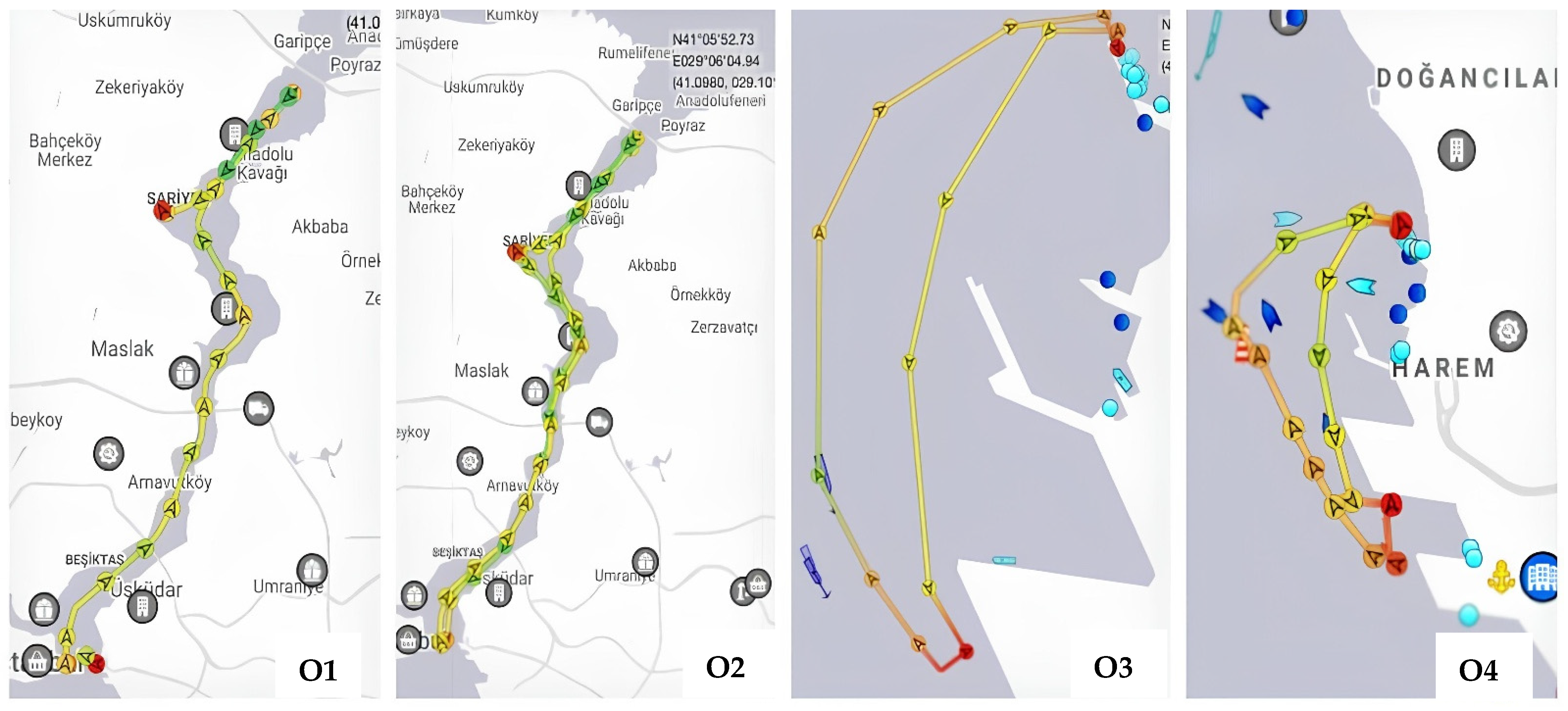
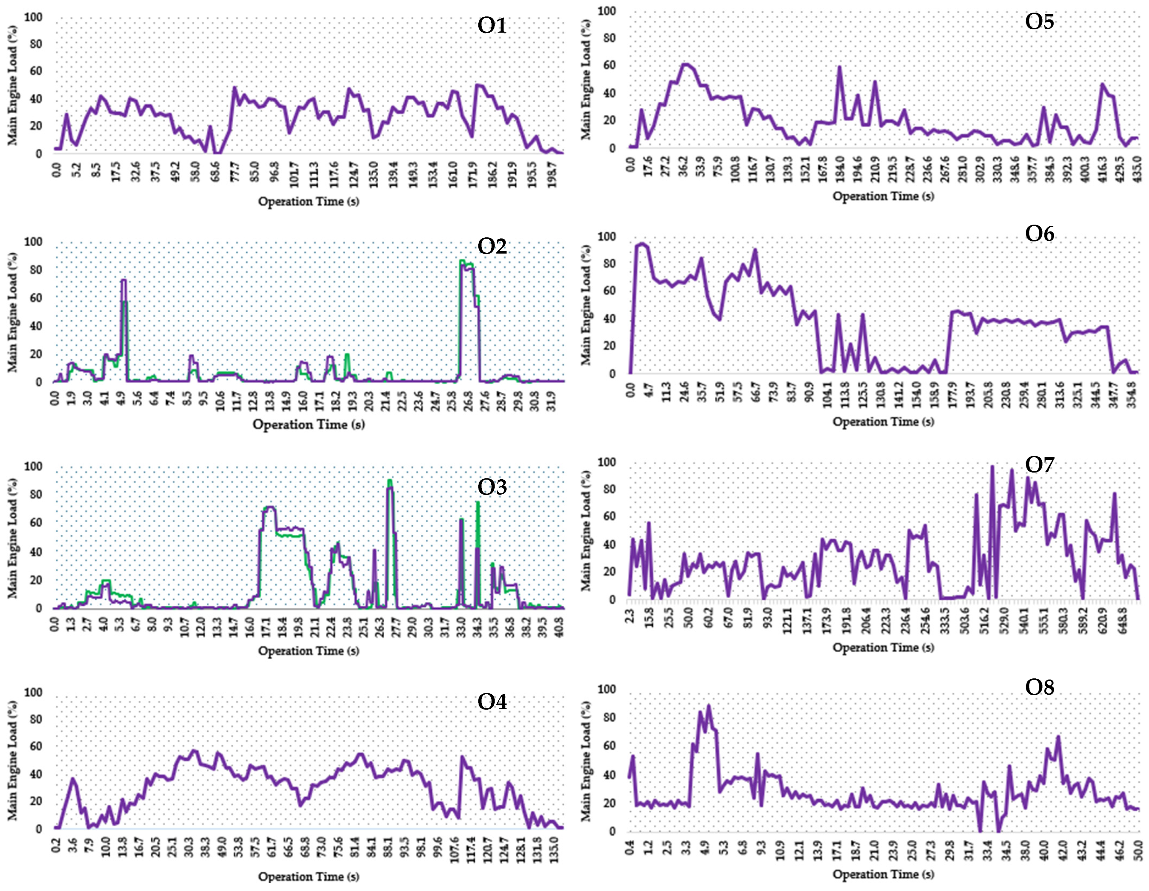
| Operation No. | Data Type | Vessel Code | Operation Time (min) | Installed Power of Main Engines and Generator Sets | The Type of Tugboat Service |
|---|---|---|---|---|---|
| O1 | Primary data | Tugboat I | 204.5 | 4200 kW/538 kW | Strait Crossing |
| O2 | Primary data | Tugboat II | 32.75 | 2280 kW/240 kW | Towing/Pushing operation |
| O3 | Primary data | Tugboat II | 41.25 | 2280 kW/240 kW | Towing/Pushing operation |
| O4 | Secondary Data | Tugboat I | 140 | 4200 kW/538 kW | Strait Crossing |
| O5 | Secondary Data | Tugboat I | 435 | 4200 kW/538 kW | Towing/Pushing operation |
| O6 | Secondary Data | Tugboat I | 387 | 4200 kW/538 kW | Strait Crossing and Towing/Pushing operation |
| O7 | Secondary Data | Tugboat I | 657.1 | 4200 kW/538 kW | Strait Crossing and Towing/Pushing operation |
| O8 | Secondary Data | Tugboat I | 50 | 4200 kW/538 kW | Towing/Pushing operation |
| Motor No | M1 | M2 |
|---|---|---|
| Output power (kW) | 500 | 250 |
| Rated speed (rpm) | 1490 | 1490 |
| Rated Current (A) | 890 | 430 |
| Rated Torque (Nm) | 3204.7 | 1602.3 |
| Power Factor (Cos φ) | 0.88 | 0.87 |
| * Efficiency | 0.951 | 0.96 |
| Weight (kg) | 1850 | 1400 |
| Volume (L) | 867.6 | 802.3 |
| No | B1 | B2 | B3 | B4 |
|---|---|---|---|---|
| Battery Type | LifePO4 | LifePO4 | Pb-Ac | Pb-Ac |
| Capacity (Ah) | 200 | 50 | 50 | 71.5 |
| Dimension (l * b * h) (mm) | 460 * 173 * 240 | 199 * 188 * 147 | 229 * 138 * 210 | 330 * 173 * 239 |
| Volume (L) | 19.1 | 5.6 | 6.6 | 13.6 |
| Weight (kg) | 23 | 7 | 18.2 | 35.3 |
| Operating Temperature | −20 °C to 60 °C | −40 °C to 55 °C | ||
| Open Circuit Voltage (change as state-of-charge) | ~3–3.4 | ~11.8–12.8 | ||
| Energy (Wh) | 2560 | 640 | 642 | 918.1 |
| Wh/L | 134 | 116.4 | 96.8 | 67.4 |
| Specific energy (Wh/kg) | 111.3 | 91.4 | 35.3 | 26 |
| Cost (USD/kWh) | 272.1 | 1273.4 | 208.7 | 435.7 |
| Life Cycle (80% DOD) | 2000 | 2500 | 360 | 400 |
| Solar Panel Code | P1 | P2 |
|---|---|---|
| Output power (W) | 80 | 190 |
| Open-circuit voltage Voc (V) | 21.76 | 22.80 |
| Short-circuit current Isc (A) | 5.12 | 10.30 |
| Peak voltage Vmp (V) | 17.80 | 18.6 |
| Peak Current Imp (A) | 4.48 | 9.95 |
| Dimension (mm) | 780 * 675 * 28 | 1480 * 670 * 30 |
| Weight (kg) | 8 | 11.9 |
| Operating and storage temperature | –40 to +85 °C | |
| Normal Operating Cell Temperature | 45 °C (±2 °C) | |
| Efficiency | ~ 20% | |
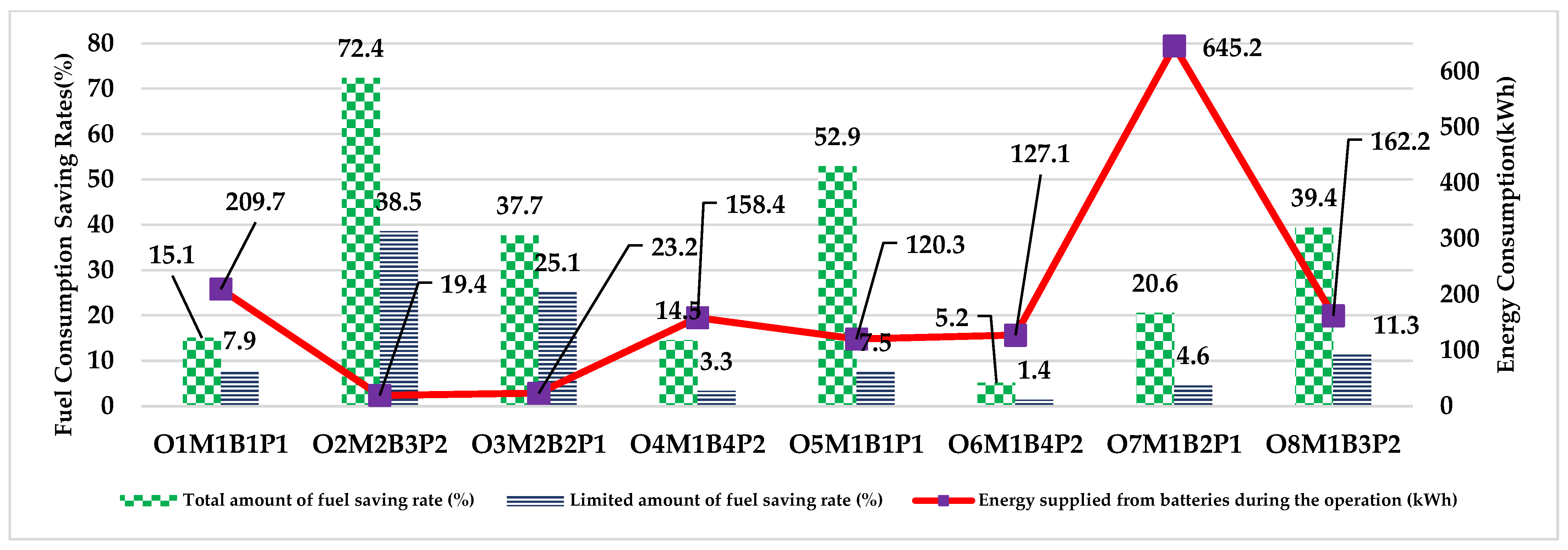
| Scenario No | I | II | III | IV | V | VI | VII | VIII |
|---|---|---|---|---|---|---|---|---|
| Op. Code | O1M1B1P1 | O2M2B3P2 | O3M2B2P1 | O4M1B4P2 | O5M1B1P1 | O6M1B4P2 | O7M1B2P1 | O8M1B3P2 |
| Operation time (s) | 12,267 | 1965 | 2475 | 8400 | 26,100 | 23,220.2 | 39,425.6 | 3001.93 |
| Low load operation time (s) | 3575.3 | 1895 | 1987 | 2528 | 18,892.4 | 6304.2 | 22,567.2 | 1492.2 |
| Total amount of fuel consumption (L) | 1007.7 | 29.2 | 64.6 | 778.3 | 1704.5 | 2145.2 | 2552.4 | 257.1 |
| Amount of low load fuel consumption (L) | 151.7 | 21.1 | 24.3 | 113.1 | 901 | 110.7 | 525.5 | 101.3 |
| Amount of low load energy consumption (Wh) | 209,707 | 19,403.2 | 23,165.5 | 158,411 | 120,268 | 127,101 | 645,169 | 162,173 |
| Number of batteries | 216 | 80 | 30 | 456 | 1238 | 366 | 830 | 666 |
| Volume of batteries (L) | 4125.4 | 530.9 | 346.9 | 6214.9 | 23,644.8 | 4988.3 | 9597.9 | 4419.4 |
| Weight of batteries (t) | 5 | 1.5 | 0.6 | 16.1 | 28.5 | 12.9 | 16.6 | 12.1 |
| Area of solar panel (m2) | 173 | 13 | 19 | 103 | 99 | 83 | 531 | 106 |
| Total amount of fuel saving rate (%) | 15.1 | 72.4 | 37.7 | 14.5 | 52.9 | 5.2 | 20.6 | 39.4 |
| Limited amount of fuel saving rate (%) | 7.9 | 38.5 | 25.1 | 3.3 | 7.5 | 1.4 | 4.6 | 11.3 |
Disclaimer/Publisher’s Note: The statements, opinions and data contained in all publications are solely those of the individual author(s) and contributor(s) and not of MDPI and/or the editor(s). MDPI and/or the editor(s) disclaim responsibility for any injury to people or property resulting from any ideas, methods, instructions or products referred to in the content. |
© 2025 by the authors. Licensee MDPI, Basel, Switzerland. This article is an open access article distributed under the terms and conditions of the Creative Commons Attribution (CC BY) license (https://creativecommons.org/licenses/by/4.0/).
Share and Cite
Nuran, M.; Bayraktar, M.; Yuksel, O. Simulation of a Hybrid Propulsion System on Tugboats Operating in the Strait of Istanbul. Sustainability 2025, 17, 5834. https://doi.org/10.3390/su17135834
Nuran M, Bayraktar M, Yuksel O. Simulation of a Hybrid Propulsion System on Tugboats Operating in the Strait of Istanbul. Sustainability. 2025; 17(13):5834. https://doi.org/10.3390/su17135834
Chicago/Turabian StyleNuran, Mustafa, Murat Bayraktar, and Onur Yuksel. 2025. "Simulation of a Hybrid Propulsion System on Tugboats Operating in the Strait of Istanbul" Sustainability 17, no. 13: 5834. https://doi.org/10.3390/su17135834
APA StyleNuran, M., Bayraktar, M., & Yuksel, O. (2025). Simulation of a Hybrid Propulsion System on Tugboats Operating in the Strait of Istanbul. Sustainability, 17(13), 5834. https://doi.org/10.3390/su17135834