Article

Valorisation of Inorganic Fractions of Waste Generated by Hydrothermal Treatment of Sewage Sludge in Alkaline Cement

1
Instituto Eduardo Torroja (IETcc), CSIC, 28001 Madrid, Spain
2
Department of Chemistry, University of Pavia, 27100 Pavia, Italy
3
Department of Earth and Environmental Sciences, University of Pavia, 27100 Pavia, Italy
4
Department of Earth and Geoenvironmental Sciences, University of Bari, 70100 Bari, Italy
*
Author to whom correspondence should be addressed.
Sustainability 2025, 17(12), 5413; https://doi.org/10.3390/su17125413
Submission received: 2 May 2025 / Revised: 3 June 2025 / Accepted: 10 June 2025 / Published: 12 June 2025
(This article belongs to the Special Issue Sustainable Materials: Recycled Materials Toward Smart Future)

Abstract

Hydrothermal processing technology provides an innovative and promising solution to achieve significant reductions in the volume of sewage sludge and the recovery of raw materials. In this work, we evaluated the possibility of using inorganic mineral residue (IMR) from hydrothermal sewage treatment in a geopolymer binder. Initially, the waste was characterised, and thermal treatment was carried out at 800 °C to eliminate the organic matter. Calcined clay (3 h at 800 °C) was used to manufacture the geopolymer. Calcined clay/residue mixtures at ratios of 100/0, 90/10, and 80/20 were prepared and activated using a 6 M NaOH solution. The pastes were cured for 20 h at 85 °C, their compressive strengths were evaluated, and the reaction products were characterised using XRD and microscopy. The results show low reactivity in the residue. However, it was observed that some of the phosphorus present in the residue could be incorporated into the products of alkaline activation. A leaching study was also carried out, in which all the toxic metals remained confined except for chromium.

1. Introduction

The global sewage sludge production has increased significantly in recent years, mainly due to the growth of urban populations and the development of wastewater treatment systems. The disposal and management of this sludge pose environmental challenges [1]. According to the United Nations, more than 60 million tonnes of sewage sludge was generated worldwide in 2022, with this quantity projected to increase by 20–30% by 2030 [2]. Together, Europe and North America account for about 45% of the total global sludge production, while Asia contributes to another 30%, with the high production in these regions driven by rapid urbanisation and industrial growth [3]. According to the European Environment Agency (EEA) [4], sewage sludge production was estimated at 12 million tonnes in Europe and about 8 million tonnes in North America in 2021, while the combined production of China and India was thought to exceed 15 million tonnes per year.
The management and use of these sludges vary between regions, but in general, about 50% of these sludges are used directly in agriculture, while only 5 to 10% are used for biofuel production; the rest are disposed of in landfills or incinerated [5].
The EU LIFE project (https://life-freedom-project.eu/ (accessed on 5 May 2025)) has proposed a plant utilising a hydrothermal liquefaction (HTL) process, in which a thermal depolymerisation process is used to convert wet biomass and other macromolecules into crude-like oil under a moderate temperature and high pressure. This is an innovative and promising solution that could significantly reduce the volume of sewage sludge and enable the recovery of raw materials from this waste. Figure 1 shows a picture of the plant, which is designed to treat up to 4000 tonnes of sewage sludge. This prototype is part of the municipal plant in Cassano d’Adda, Italy, and is managed by the CAP Holding Group of Milan.
This project proposal involves the mass production of devices with dimensions similar to those in Figure 1. Systems with dimensions significantly different from those of the demonstration system would require a new thermodynamic design and could affect the competitive and commercial advantages associated with the possible mass production of these devices. Therefore, the FREEDOM technology’s success depends on the possibility of creating this type of system. SYNGEN has already filed a patent for this technology and the HTL sludge treatment method.
As part of the LIFE project, an HTL demonstration plant has been designed that recovers solid waste using material flows in a closed circuit to achieve maximum sustainability, resulting in different products. The project’s objectives are as follows: (i) the recovery of water in a form that allows for its immediate reuse; (ii) the production of synthetic crude oil, a mixture of hydrocarbons suitable for processing at a conventional oil refinery (biofuels) or use in the asphalt industry (bituminous material); (iii) phosphorus recovery for agricultural applications (phosphate fertiliser production); (iv) and the production of binding materials using inorganic mineral residues (IMRs), which can be recovered in combination with other precursors (cement, fly ash, slag, and clays). This work focused on the latter: the incorporation of IMRs into alkaline cement or geopolymers.
At this point, it should be noted that no data are available on the process used, as they are industrially protected by the company that manages the plant. The only information available is that the sludge was treated in the LIFE FREEDOM demonstration plant at a temperature of 220 °C for a residence time of 30 min. These conditions fall within the P-T range of the hydrothermal process known as HTC, or hydrothermal carbonisation [6,7]. The duration of the hydrothermal process was 30 min, which, although insufficient to carbonise the organic mass, would allow the sludge to be dehydrated and filtered, thereby reducing the water content and thus the volume of the resulting solid product. This work focused only on characterising the final solid inorganic residue left after the completion of the whole process and the feasibility of using it in cementitious matrices. The IMR obtained at the end of the process underwent an additional heat treatment to improve its reactivity and was used as an additive (at 0, 5, 10, and 20%) to an alkaline cement.
Alkaline cements or geopolymers are types of binders formed by dissolving aluminosilicates with amorphous or glassy structures in an alkaline medium [8,9,10]. When mixed with alkaline activators, these materials set and harden, resulting in a material with good binding properties [11,12,13]. A wide range of natural raw materials and industrial by-products can be used as precursors for alkaline cements. The most commonly used materials are blast furnace slag [14,15,16], fly ash [16,17,18], and metakaolin [19,20,21]. However, several other silicoaluminous materials can be used as precursors [22,23].
Geopolymers are also considered sustainable binders due to their low CO2 emissions compared to traditional Portland cement-based concrete [24,25,26,27] and the potential for reduced energy consumption. Furthermore, geopolymers offer increased durability, especially against acid attacks, and fire resistance, which provides structures with long-term sustainability [28,29,30].
The objective of this study was to determine the technical feasibility of valorising the IMR obtained from hydrothermal sewage sludge treatment in geopolymer binders. As the geopolymer precursor, we selected a common, low-quality clay, heat-treated to increase its reactivity, due to its availability in the environment where the THL plant was installed and the lack of significant applications in other fields. Different percentages of IMR (0, 5, 10, and 20%) were incorporated into this geopolymer. Finally, leaching tests (in accordance with the UNI-EN 12457-2 standard) were performed to verify that the potential presence of heavy metals in the IMR-containing binder would not cause leaching problems.

2. Materials and Methods

In the present work, low-grade calcined clay was used as the precursor of the geopolymeric matrix, and the IMR was obtained from sludge treated in the LIFE FREEDOM demonstration plant. Both materials were characterised using different techniques (TG/DTG, XRF, and XRD) and then subjected to heat treatment at 800 °C for 3 h to improve their reactivity.
Pastes were prepared by adding a 6 M NaOH solution to these heat-treated materials as an activator. The pastes’ composition, alkaline solution/binder ratio, and initial curing conditions during the pastes’ preparation are given in Table 1. The solution/binder ratio was increased by increasing the IMR content in the binders (see Table 1). Prismatic specimens were prepared using these pastes (one mould containing 6 (1 × 1 × 6 cm3) specimens per material and test age). The cements were first cured for 20 h at 85 °C and a relative humidity > 90%. They were then demoulded and stored in a curing chamber until reaching the test ages (2 and 28 days).
The cement’s compressive strength was tested using an IBERTEST AUTOTEST-200/10 SW testing machine (IETcc, Madrid, Spain). Six prismatic specimens were tested for each binder composition and age. After the compression tests, the specimens were ground in a porcelain mortar, and the hydration process was stopped with isopropyl alcohol [20]. The samples were then filtered through a 1.6 µm porous filter and stored under vacuum in a desiccator until completely dry, at which point they were analysed using XRD. Half of the specimens were not subjected to compression tests and were placed in isopropanol and stored under vacuum for seven days.
A TA SDT Q 600 (IETcc, Madrid, Spain) was used to analyse the raw materials through TG/DTG. The recording conditions involved heating the materials from room temperature to 1000 °C at 10 °C/min in a platinum crucible under a nitrogen atmosphere. The sensitivity of the measurement was 0.001 °C for DTG and 0.1 µg for TG.
An XRD analysis was carried out using a BRUKER D8 ADVANCE diffractometer (IETcc, Madrid, Spain) with a 3 KW high-voltage generator, a copper anode X-ray tube (Cu Kα1,2, radiation of 1.540 Å) operating at 40 kV and 50 mA, a Lynxeye detector with a 3 mm anti-scatter slit, and a Ni K-beta filter (0.5 %), without a monochromator for Kα2 removal.
A HITACHI S-4800 field emission gun (FEG) microscope (IETcc, Madrid, Spain) with a resolution of 1.4 nm was used for the microscopy studies. This instrument has a backscattered electron detector (BSEM), Bruker X-ray detector, microanalysis software (QUANTAX 400), and five controlled axes. For SEM analyses, the samples were vacuum-dried and carbon-metallised. For BSEM analyses, they were embedded in epoxy resin.
Leaching tests were carried out on sample Ar80 (at 28 days) in accordance with the UNI-EN 12457-2 standard “Leaching-Compliance test for leaching of granular waste material and sludge.” This procedure was selected to ensure the most rigorous conditions possible, thereby quantifying the maximum number of leachable elements, in accordance with the precautionary principle. The procedure included the following preparatory steps: (1) Each cement sample was ground and sieved. For each sample, 3 g of material measuring less than 4 mm was used, along with 3 mL of triple-distilled water. The mixtures were then agitated on a shaker (at approximately 10 rpm) for 24 h. (2) The samples were then left to settle for 15 min before being centrifuged at 2000 g for 30 min to facilitate solid–liquid separation. Approximately 20 mL of the eluate was then filtered through a 0.45 µm filter and acidified by adding 1% of the total volume of ultra-pure HNO3 (analytical grade). (3) A triple-distilled water benchmark sample was prepared, and the concentrations of As, Pb, Ni, Cu, Cr, Zn, and Cd were determined using ICP-OES.

3. Results and Discussion

3.1. Material Characterisation

Figure 2 shows the physical appearance of the IMR at the end of the hydrothermal process after being filter-pressed (original IMR), dried at 100 °C, and heat-treated at 800 °C, as well as an image of the clay after heat treatment.
Both materials were characterised using TG/DTG, and the results are shown in Figure 3. The IMR showed high weight losses at temperatures ranging between 100 and 1000 °C (≈52.53%). During the calcination process, an odour characteristic of the decomposition of organic compounds was released [6]. Therefore, these weight losses were mostly related to the presence of organic matter in the residue. The temperature reached during the hydrothermal process (30 min residence time at 220 °C) was not sufficient to remove all the organic residues and moisture. It should be noted that no data are available on the nature of the gases released. Tests to determine the organic phases that the IMR may have contained were beyond the scope of this work and will be addressed in another study. This work focused only on the inorganic characterisation of the final solid residue remaining at the end of the process and its suitability for use in cementitious matrices.
Based on the DTG results, the chemical and mineralogical compositions of the IMR were determined after treatment at 100 °C for 24 h, 800 °C for 3 h, and 1000 °C for 3 h. Table 2 shows the chemical composition values (percentage of oxides by weight, determined using X-ray fluorescence, XRF). The main oxides were Fe2O3 and P2O5 (Fe2O3 + P2O5 ≈ 25.6%). However, for the valorisation of this waste as a binder, the sum of the CaO + SiO2 + Al2O3 oxide content in IMR-100 was low, ~17.28%. After the heat treatment, the oxides were enriched: at 800 °C, the Fe2O3 + P2O5 content increased to 47.3%, and the CaO + SiO2 + Al2O3 content increased to 38.85%. However, these values were still low. In IMR-1000, the values increased slightly more but were very similar to those of IMR-800.
The diffractograms of the IMR after the heat treatments are shown in Figure 4. At 100 °C, the material lost a significant amount of its moisture: 3.8%. The IMR-100 diffractogram only showed amorphous phase signals with quartz peaks. This material cannot be used in this state because, despite being mostly amorphous, it still contains many organic phases, which give off odours. After calcination at 800 °C and 1000 °C, there was a significant loss of weight, as shown in Figure 3, mainly due to the loss of moisture and organic phases, but the material also recrystallised. Figure 4 shows that, at both 800 °C and 1000 °C, in addition to quartz and cristobalite, crystalline phases rich in phosphorus or iron could be detected, such as haematite, aluminium phosphate (AlPO4), and aluminium calcium phosphate (Ca9Al(PO4)7). The mineralogical composition is important for the valorisation of mineral waste because, as we will see later, some of these crystalline phases are not very reactive. However, when finely ground, these phases can act as fillers [31,32].
Based on these results, calcination for 3 h at 800 °C was considered sufficient to eliminate the remains of any organic phases IMR may contain. After calcination at 800 °C, the IMR did not give off any odour, so there was no need to calcine it at a higher temperature. The characterisation results show that the chemical and mineralogical composition of this waste made it unsuitable for use as the sole precursor for an alkaline cement. It was therefore considered more suitable for use as a minor component of alkaline cement.
A low-grade clay that had been heat-treated for 3 h at 800 °C was used as a precursor for the alkaline cement. Figure 3 shows the DTG and TG curves of the clay. Table 2 shows the chemical composition of the clay before and after calcination, and Figure 5 shows the diffractograms of the original and heat-treated clay.
The clay was characterised by a high calcium content (21.22%), mainly due to the presence of carbonates: calcite and dolomite. It also contained other crystalline phases such as quartz and aluminosilicates such as kaolinite and muscovite [33,34].
In the TG/DTG curve for the clay, the signals present below 300 °C (an intense signal at 53 °C, shoulder at 112 °C and low-intensity signals at 173 °C and 236 °C) were mainly associated with the loss of water from the clay structure. The signal at 480 °C was associated with weight loss due to dehydroxylation reactions involving kaolinite. The peak at 730 °C was mainly related to carbonate decomposition, leading to the release of CO2 [34,35]. The diffractogram of the clay at 800 °C (Figure 4) confirmed the TG/DTG results. The peaks associated with kaolinite disappeared due to the dehydroxylation of the clay mineral structure and kaolinite’s transformation into metakaolin [12]. According to Danner et al. [34,35], muscovite peaks are visible up to 1000 °C. The calcite signal was no longer evident because the carbonates had decomposed [35,36,37,38], while a lime signal appeared. The quartz signal did not change. In addition to lime, gehlenite (Ca2Al2SiO7) was detected as a new phase.
Based on these results, it was considered possible that the same calcination process could be carried out for both materials for 3 h at 800 °C.
The selected materials, Ar-800 and IMR-800, were ground. Figure 6 shows the particle size distribution of both materials, determined through laser granulometry using a COULTER LS 130 granulometric analyser with a measurement range of 0.1–900.0 µm. In total, 95% of the particles in the Ar-800 °C sample were smaller than 45 µm; in the IMR 800 °C sample, 85% of the particles were smaller than 45 µm. Using these calcined materials, the mixtures shown in Table 1 were prepared. The results of the alkaline activation of these mixtures are shown below.

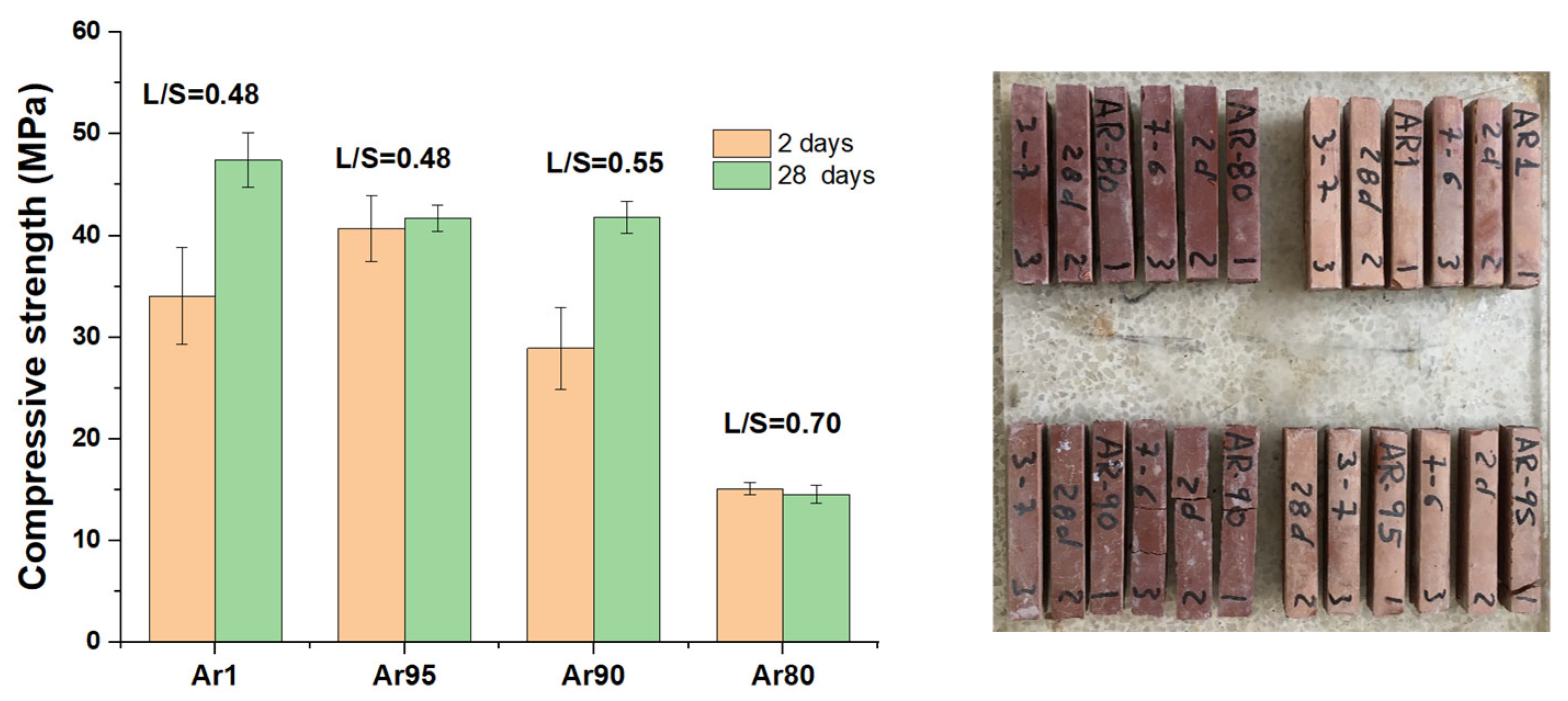
3.2. Alkaline Activation

Table 3 shows that the CaO + SiO2 + Al2O3 content of the selected blends (Ar95, Ar90, and Ar80) exceeded 75%, a value considered adequate for producing alkaline cements. The table also shows the CaO/SiO2 and Al2O3/SiO2 ratios of the binders studied. The calcium content in Ar-800 was higher than that when fly ash or metakaolin were used as precursors [17,18,19,20,21] but lower than when blast furnace slag was used. In previous work [35], it was shown that, for calcic clays, the most suitable concentration of NaOH was around 6 or 8M. Based on the results obtained in these previous studies [35] and a series of preliminary tests carried out in our laboratory, a NaOH concentration of 6 M was selected for the activator in this study, and initial curing took place for 20 h at 85 °C and 95 % RH. The liquid/solid ratio (L/S = 6 M NaOH/binder) was increased with the IMR content in order to obtain a similar workability.
Figure 7 shows the compressive strength values obtained using the three binders. As the residue content (IMR) in the binders increased, the mechanical strength decreased. This decrease may have partly been due to the need to significantly increase the L/S ratio. In any case, from a mechanical development point of view, an IMR content of 10% (Ar90) may be adequate. A content of 20% (Ar80) resulted in significantly lower compressive strength values. However, these values may be considered adequate for some non-structural applications.
The largest differences in the compressive strength values were observed at a residue content of 20%; therefore, the Ar80 binder pastes were selected for characterisation.

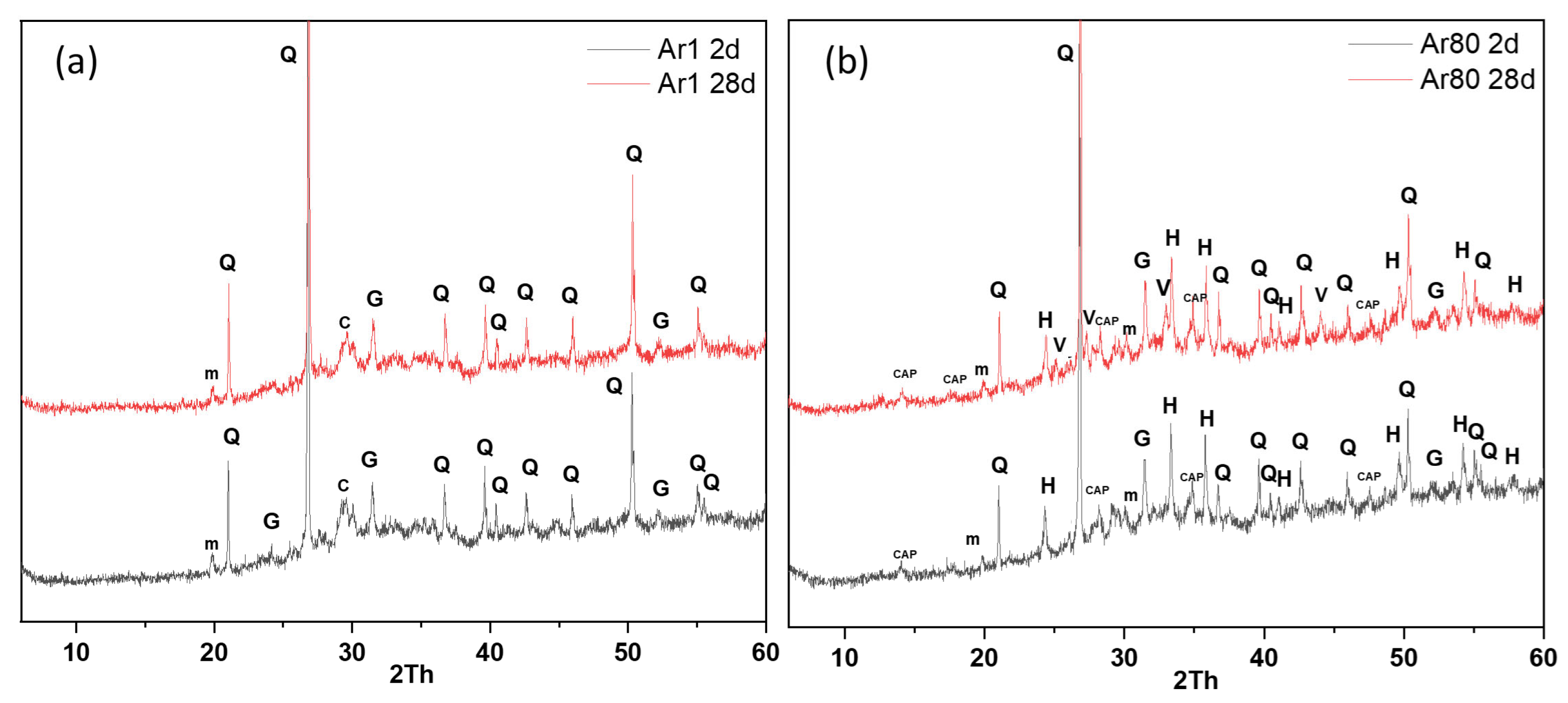
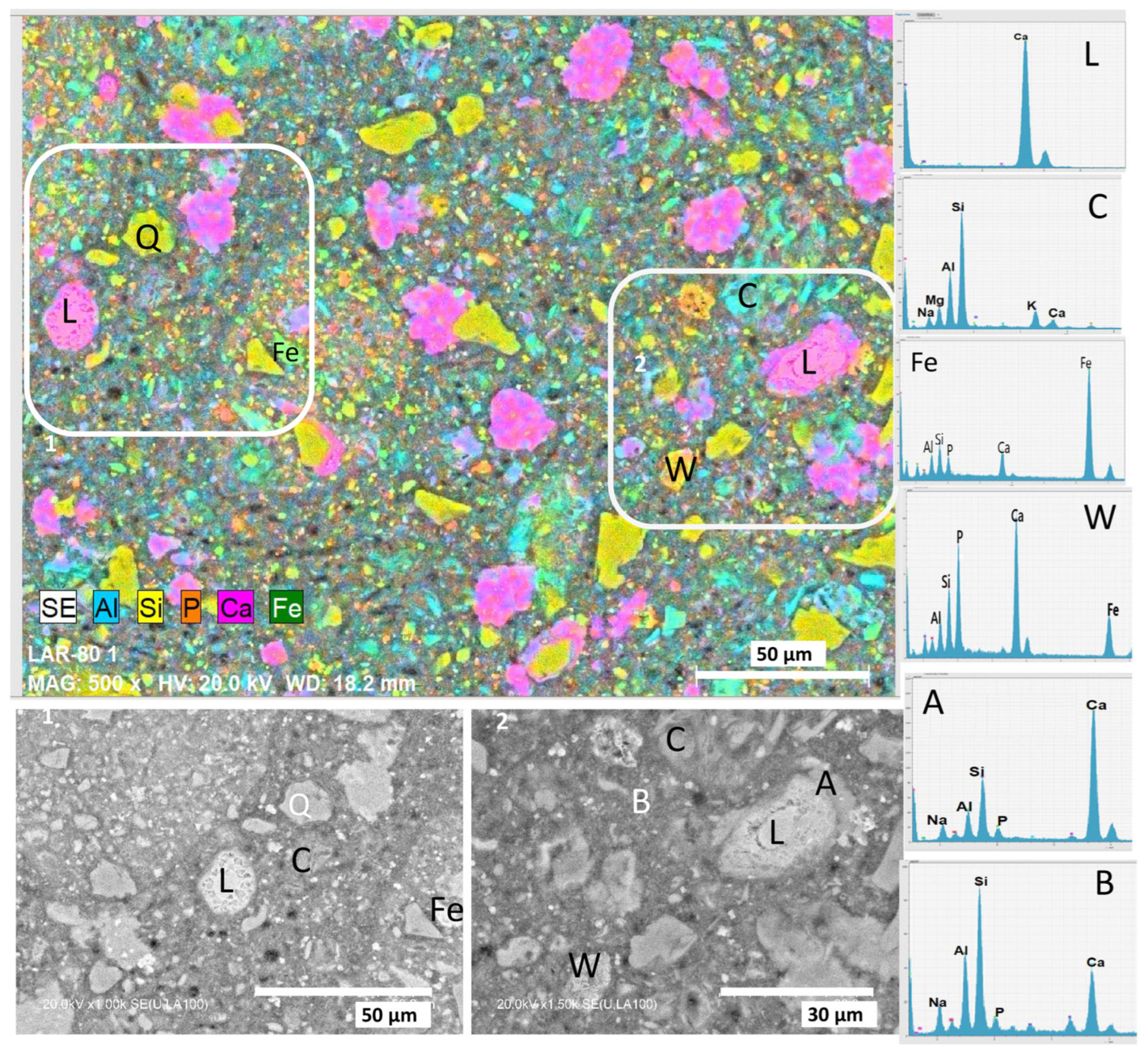
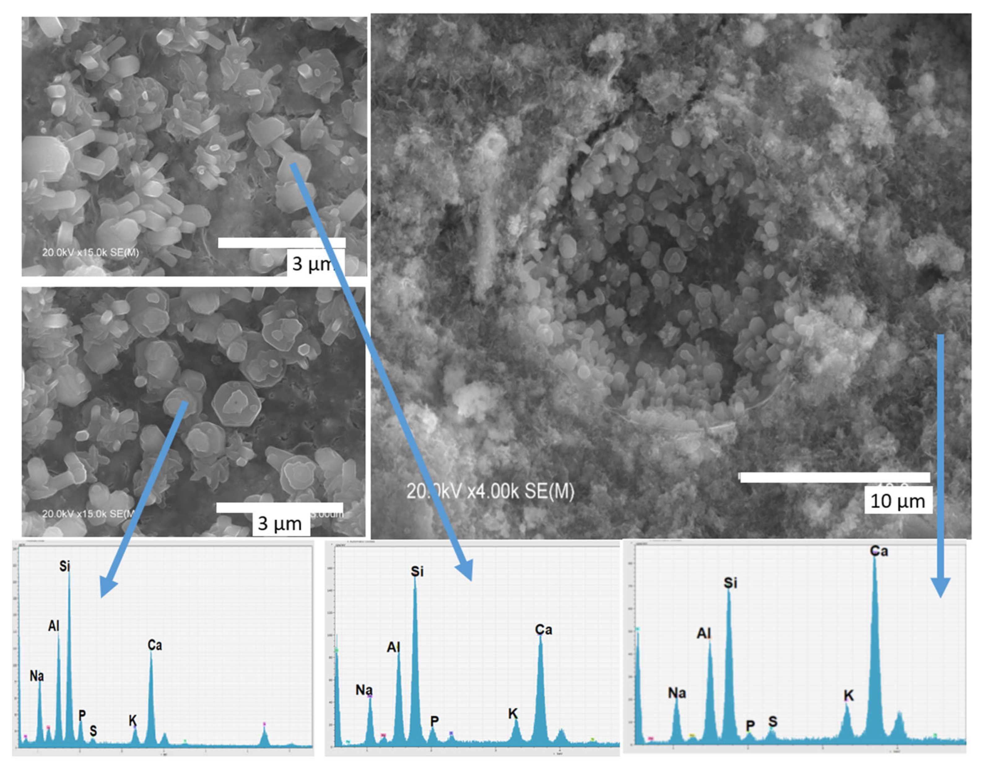
3.2.1. Characterisation of the Reaction Products

Figure 8 shows the diffractograms of the Ar1 (reference) and Ar80 pastes at 2 and 28 days. Regarding the Ar1 sample, it was observed that the crystalline phases in the calcined clay were retained, except for that of lime (this signal disappeared). No new crystalline phases were observed. The amorphous halo was slightly displaced at 2θ values between 25 and 35°; this displacement, according to the literature, is associated with the formation of an amorphous N-A-S-H (Na2O-Al2O3-SiO2-H2O) cementitious gel.
Regarding the Ar80 binder (20% residue), in addition to the peaks associated with the crystalline phases of Ar-800, peaks associated with the crystalline phases of the residue (haematite and aluminium calcium phosphate) were detected. No lime was observed, while the presence of calcium carbonate in the form of vaterite was detected. The main reaction product formed was an amorphous gel or mixture of gels, which was characterised through an electron microscopic study.
Figure 9 shows the appearance of the Ar80 binder matrix after 28 days, with different zones enlarged. Present in the matrix were CaO-rich particles (L, pink), possibly lime from the decarbonation of the clay (Ar) that had not yet reacted. The points marked C (calcium-poor) were associated with unreacted calcined clay particles consisting mainly of Si and Al (possibly metakaolin). The yellow particles (Q) were very rich in SiO2, mainly associated with quartz from both the clay and IMR, as quartz is virtually inert. The iron-rich green (Fe) particles were associated with the presence of haematite, as detected using XRD. Shown in orange, the phosphorus-rich particles were mainly associated with unreacted IMR (at point W), although phosphorus was also observed to be somewhat generally distributed throughout the matrix.
The matrix consisted mainly of a CaO-SiO2-Al2O3 mixture (points A and B), with some sodium and phosphorus. A variation in the phase intensity was observed, associated with the formation of different types of (N,C)-A-S-H gels with low and high calcium contents [37,38,39,40,41].
Figure 10a shows the chemical composition at 100 points, ordered from the lowest to the highest calcium content. It can be seen that as the calcium content increased, the silica and aluminium content decreased. Also noteworthy is the association between particles with high Fe and P contents and the IMR particles embedded in the matrix, as indicated above. The EDX results indicate the presence of phosphorus (P2O5 ≈ 6%) in the gel, suggesting that some of the phosphorus in the sludge is incorporated into the cementitious gels.
In order to better analyse the composition of the cementitious gel formed, we determined the molar percentages of SiO2, CaO, and Al2O3, normalised to 100% and shown in Figure 10b. This representation clearly shows the formation of different types of gels in the matrix. The dots within the red circle were associated with the formation of a hydrated sodium calcium sodium aluminosilicate gel ((N,C)-A-S-H) [37]. In this region, two zones can also be distinguished. The first includes gels poorer in calcium and therefore more similar to the N-A-S-H gels formed in the activation of fly ash or metakaolin [17,18,19,20], whereas the second includes gels with more calcium, belonging to the N-(C)-A-S-H type. This gel was associated with the reactions of aluminosilicates in the clay, the Ca content of which may have been enriched close to where these lime particles were found. This gel was enriched in calcium and could be considered (N)-C-A-S-H. On the other hand, the dots in the green circle were associated with the formation of a C-(A)-S-H-type gel and the areas surrounding the lime particles, which resulted from the decarbonation of limestone. This lime reacted to form a C-S-H-type gel with a low Al content. The formation of these phases has also been observed by other authors in the activation of clays with calcite [36], the alkaline activation of fly ash and slag mixtures [41,42], and hybrid alkaline cements [43].
The same sample was also analysed using SEM, and several micrographs are shown in Figure 11. The morphology of the gel was very similar to that obtained through the alkaline activation of calcined clays [44]. In the voids, we observed particles with a hexagonal or rod morphology and a composition rich in Si, Al, and Na, associated with the presence of zeolites. These particles also contained a small amount of phosphorus.

3.2.2. Leaching Tests

Table 4 shows the results of the leaching tests carried out on Ar80 material aged 28 days. The procedure was described in the Section 2 and was in accordance with UNI-EN 12457-2. Table 4 also shows the permissible limits for heavy metals in landfill leachate and drinking water. These limits may vary according to the regulations of each country or region; here, we used the average values recommended by the World Health Organisation (WHO) [36] and the United States Environmental Protection Agency (EPA) [45,46].
Almost all the elements measured were within the legal limits, with the exception of Cr. The ability of alkaline cements and geopolymers to immobilise heavy metals has been extensively reported in the literature [47,48,49]. The unique properties of alkaline cements make them highly effective in stabilising and solidifying hazardous waste containing heavy metals (e.g., Pb, Ni, Cu, Zn, and Cd). Studies have shown that geopolymers immobilise these substances through physical encapsulation and chemical bonding, resulting in the production of materials that resist leaching under various environmental conditions [47,48,49]. However, these processes are not as effective at binding chromium, which significantly alters the mechanism of the alkaline activation of fly ash or metakaolin [48]. Palomo and Palacios [47] observed that the addition of 2.6% Cr6+ by weight as CrO3 inhibited setting in fly ash samples activated with sodium hydroxide. This process was attributed to the formation of Na2CrO4 4H2O. Although the formation of this compound could not be detected using XRD, it is very possible that its formation and leaching were partly responsible for the decreased mechanical strength of AR80.
It is important to remember that, unlike organic pollutants, heavy metals are not biodegradable and can persist in the environment, forming stable and irreversible compounds. These metals can exist in different chemical forms, which makes their environmental impact more complex. The results obtained in this work show that IMR could be incorporated as an additive in alkaline cements, although the matrix needs to be improved to avoid the possible leaching of Cr. In this respect, numerous studies in the literature mention the possibility of using inorganic stabilisers such as sodium sulphide (Na2S) [50,51,52], iron-based reductants (FeCl2 and FeSO4) [53,54], and organic chelating agents such as DTC and TMT [55,56]. These agents promote chemical reactions that convert toxic metal ions, such as Cr (VI), into less mobile and toxic forms, thereby significantly improving the effectiveness of the matrix in immobilising them. Further research will therefore be required on this type of application to determine whether these stabilisers will aid in fixing chromium in these matrices.

4. Conclusions

The results obtained in this study indicate that after performing calcination to remove all organic matter, the residue obtained from the hydrothermal treatment of sewage sludge can be used as a component in alkaline cements to produce alkaline-activated binders. The reactivity of the residue was low, with iron present in the residue in the form of haematite acting mainly as an inert agent. The phosphorus compounds also act partly as inert agents, although a small proportion of phosphorus appeared to be incorporated into cementitious gel and zeolite reaction products.
The incorporation of up to 20% IMR in geopolymers based on calcined low-grade clay matrices resulted in the production of materials with mechanical strengths of around 15 MPa; these values were much higher when only 10% IMR (≈40 MPa) was used. Depending on the application, the recommended level of substitution will be higher or lower. Under these conditions, a mixture of cemented (C,N)-A-S-H and C-(A)-S-H gels containing a small amount of phosphorus is the main reaction product.
Several factors were taken into account when selecting the calcined clay to mix with the residue to produce alkali-activated binders. The addition of reactive materials rich in SiO2, Al2O3, and CaO, such as calcined clays, can help to compensate for the deficiency of these oxides in the mineral residue, significantly improving the properties of the final products. Furthermore, clays can be found almost anywhere, helping to reduce the logistical costs of transporting materials and contributing to the production of an economically and environmentally sustainable binder.
Finally, it should be noted that this matrix containing 20% IMR can retain the heavy metals present in IMRs, with the exception of chromium. Further research in this area is recommended, focusing on the improvement of the inclusion matrix or the use of chemical stabilisers.

Author Contributions

Conceptualisation, A.P., A.F.-J. and S.C.T.; methodology, A.F.-J., O.M., M.S., S.C.T. and M.Z.; validation, A.F.-J., O.M., N.M.M., M.S. and S.C.T.; formal analysis, A.F.-J. and O.M.; investigation, A.P., A.F.-J., N.M.M., M.S. and S.C.T.; resources, A.P., A.F.-J., M.P.R., M.S. and S.C.T.; writing—original draft preparation, A.F.-J.; writing—review and editing, A.F.-J., S.C.T. and M.Z.; visualisation, A.P. and N.M.M.; supervision, A.P., M.S., S.C.T. and M.Z.; project administration, A.F.-J.; funding acquisition, A.F.-J. and S.C.T. All authors have read and agreed to the published version of the manuscript.

Funding

The authors wish to thank the European Union for conducting the project LIFE19 ENV IT 000165—LIFE FREEDOM.

Institutional Review Board Statement

Not applicable.

Informed Consent Statement

Not applicable.

Data Availability Statement

The data are contained within the article.

Conflicts of Interest

The authors declare no conflicts of interest.

Abbreviations

The following abbreviations are used in this manuscript:
HTLHydrothermal liquefaction process
IMRInorganic mineral residue
XRDX-ray diffraction
PDFPower Diffraction File
TG/DTGThermogravimetric analysis/derivative thermogravimetric Analyses
EDXEnergy-dispersive X-ray spectroscopy

References

  1. Christopher Selvam, D.; Yuvarajan Devarajan Raja, T. Sewage sludge as a sustainable feedstock for biodiesel: Advances in conversion technologies and catalytic applications. Results Eng. 2025, 25, 104000. [Google Scholar] [CrossRef]
  2. Zhang, O.; Gao, L.; Li, W.; Xiao, L. Predicting sludge generation patterns carbon reduction potential under shared socioeconomic pathways. J. Environ. Manag. 2022, 322, 116088. [Google Scholar] [CrossRef]
  3. Aryanfar, Y.; Keçebas, A.; Nourbakhsh, A.S.; García, J.L.A.; Fernández, B.; Wu, W. Production of biodiesel from industrial sludge: Recent progress, challenges, perspective. Processes 2024, 12, 2517. [Google Scholar] [CrossRef]
  4. Agencia Europea de Medio Ambiente (AEMA). Urban Waste Water Treatment for 21st Century Challenges. Available online: https://www.eea.europa.eu/en/analysis/publications/urban-waste-water-treatment-for (accessed on 5 May 2025).
  5. Krause, M.J.; Bronstein, K. Estimating national sludge generation disposal from US drinking water wastewater treatment plants. J. Clean. Prod. 2024, 453, 142121. [Google Scholar] [CrossRef]
  6. Fan, Y.; Hornung, U.; Dahmen, N. Hydrothermal liquefaction of sewage sludge for biofuel application: A review on fundamentals, current challenges and strategies. Biomass Bioenergy 2022, 165, 106570. [Google Scholar] [CrossRef]
  7. Zhang, X.; Li, X.; Li, R.; Wu, Y. Hydrothermal Carbonization and Liquefaction of Sludge for Harmless and Resource Purposes: A Review. Energy Fuels 2020, 34, 13268–13290. [Google Scholar] [CrossRef]
  8. Guo, S.; Wu, Y.; Jia, Z.; Qi, X.; Wang, W. Sodium-based activators in alkali-activated materials: Classification and comparison. J. Build. Eng. 2023, 70, 106397. [Google Scholar] [CrossRef]
  9. Matsimbe, J.; Dinka, M.; Olukanni, D.; Musonda, I. Geopolypmer: A Systematic Review of Methodologies. Mater 2022, 15, 6852. [Google Scholar] [CrossRef]
  10. Ahmad, M.R.; Fernández-Jiménez, A.; Chen, B.; Bing, L.; Leng, Z.; Dai, J.G. Low-carbon cementitious materials: Scale-up potential, environmental impact and barriers. Constr. Build. Mater. 2024, 455, 139087. [Google Scholar] [CrossRef]
  11. Khalifa, A.Z.; Cizer, O.; Pontikes, Y.; Heath, A.; Patureau, P.; Bernal, S.A.; Marsh, A.T.M. Advances in alkali-activation of clay minerals. Cem. Concr. Res. 2020, 132, 106050. [Google Scholar] [CrossRef]
  12. Provis, J.L. Alkali-activated materials. Cem. Concr. Res. 2018, 114, 40–48. [Google Scholar] [CrossRef]
  13. Kryvenko, P.; Rudenko, I.; Sikora, P.; Sanytsky, M.; Konstantynovskyi, O.; Kropyvnytska, T. Alkali-activated cements as sustainable materials for repairing building construction: A review. J. Build. Engin. 2024, 90, 109399. [Google Scholar] [CrossRef]
  14. Rodríguez, E.; Bernal, S.; Mejía de Gutiérrez, R.; Puertas, F. Alternative concrete based on alkali-activated slag. Mater. Construcción 2008, 58, 53–67. [Google Scholar] [CrossRef]
  15. Haha, M.B.; Lothenbach, B.; Le Saout, G.; Winnefeld, F. Influence of activator type on hydration kinetics, hydrate assemblage and microstructural development of alkali activated blast furnace slags. Cem. Concr. Res. 2012, 42, 74–83. [Google Scholar] [CrossRef]
  16. Fu, Q.; Bu, M.; Zhang, Z.; Xu, W.; Yuan, Q.; Niu, D. Hydration Characteristics and Microstructure of Alkali-Activated Slag Concrete: A Review. Res. Civ. Eng. Mater.―Rev. Eng. 2023, 20, 162–179. [Google Scholar] [CrossRef]
  17. Boakye, K.; Khorami, M. Impact of Low-Reactivity Calcined Clay on the Performance of Fly Ash-Based Geopolymer Mortar. Sustainability 2023, 15, 13556. [Google Scholar] [CrossRef]
  18. Hoyos-Montilla, A.; Tobón, J.I.; Puertas, F. Role of calcium hydroxide in the alkaline activation of coal fly ash. Cem. Concr. Compos. 2023, 137, 104925. [Google Scholar] [CrossRef]
  19. Ma, Y.; Gong, J.; Ye, G.; Fu, J. Effect of Activator and Mineral Admixtures on the Autogenous Shrinkage of Alkali-Activated Slag/Fly Ash. Sustainability 2023, 15, 16101. [Google Scholar] [CrossRef]
  20. Khalifa, A.Z.; Pontikes, Y.; Elsen, J.; Cizer, Ö. Comparing the reactivity of different natural clays under thermal and alkali activation. RILEM Tech. Lett. 2019, 4, 74–80. [Google Scholar] [CrossRef]
  21. Cao, Y.; Wang, Y.; Zhang, Z.; Ma, Y.; Wang, H. Recent progress of utilization of activated kaolinitic clay in cementitious construction materials. Compos. Part B Eng. 2021, 211, 108636. [Google Scholar] [CrossRef]
  22. Rivera, J.; Castro, F.; Fernández-Jiménez, A.; Cristelo, N. Alkali-activated cements from urban, mining and agro-industrial waste: State-of-the- art and opportunities. Waste Biomass Valorization 2021, 12, 2665–2683. [Google Scholar] [CrossRef]
  23. Occhipinti, R.; Fernández-Jiménez, A.; Palomo, A.; Tarantino, S.C.; Zema, M. Sulfate-bearing clay and Pietra Serena sludge: Raw materials for the development of alkali activated binders. Constr. Build. Mater. 2021, 301, 124030. [Google Scholar] [CrossRef]
  24. Turner, L.K.; Collins, F.G. Carbon dioxide equivalent (CO2-e) emissions: A comparison between geopolymer and OPC cement concrete. Constr. Build. Mater. 2013, 43, 125–130. [Google Scholar] [CrossRef]
  25. Neupane, K. Evaluation of environmental sustainability of one-part geopolymer binder concrete. Clean. Mater. 2022, 6, 100138. [Google Scholar] [CrossRef]
  26. Liu, M.; Dai, W.; Jin, W.; Li, M.; Yang, X.; Han, Y.; Huang, M. Mix proportion design and carbon emission assessment of high strength geopolymer concrete based on ternary solid waste. Sci. Rep. 2024, 14, 24989. [Google Scholar] [CrossRef] [PubMed]
  27. Cong, P.; Du, R.; Gao, H.; Chen, Z. Comparison and assessment of carbon dioxide emissions between alkali-activated materials and OPC cement concrete. J. Traffic Transp. Eng. 2024, 11, 918–938. [Google Scholar] [CrossRef]
  28. Amran, M.; Al-Fakih, A.; Chu, S.H.; Fediuk, R.; Haruna, S.; Azevedo, A.; Vatin, N. Long-term durability properties of geopolymer concrete: An in-depth review. Case Stud. Constr. Mater. 2021, 15, e00661. [Google Scholar] [CrossRef]
  29. Wong, L.S. Durability Performance of Geopolymer Concrete: A Review. Polymers 2022, 14, 868. [Google Scholar] [CrossRef]
  30. Paruthi, S.; Rahman, I.; Khan, A.H.; Sharma, N.; Alyaseen, A. Strength, durability, and economic analysis of GGBS-based geopolymer concrete with silica fume under harsh conditions. Sci. Rep. 2024, 14, 31572. [Google Scholar] [CrossRef]
  31. Berodier, E.; Scrivener, K. Understanding the Filler Effect on the Nucleation and Growth of C-S-H. J. Am. Ceram. Soc. 2014, 97, 3764–3773. [Google Scholar] [CrossRef]
  32. Poppe, A.M.; De Schutter, G. Cement hydration in the presence of high filler contents. Cem. Concr. Res. 2005, 35, 2290–2299. [Google Scholar] [CrossRef]
  33. Fernandez, R.; Martirena, F.; Scrivener, K.L. The origin of the pozzolanic activity of calcined clay minerals: A comparison between kaolinite, illite and montmorillonite. Cem. Concr. Res. 2011, 41, 113–122. [Google Scholar] [CrossRef]
  34. Danner, T.; Justnes, H. The Influence of Production Parameters on Pozzolanic Reactivity of Calcined Clays. Nord. Concr. Res. 2018, 59, 1–12. [Google Scholar] [CrossRef]
  35. Dannera, T.; Nordenb, G.; Justnes, H. Characterisation of calcined raw clays suitable as supplementary cementitious materials. Appl. Clay Sci. 2018, 162, 391–402. [Google Scholar] [CrossRef]
  36. D’Elia, A.; Pinto, D.; Eramo, G.; Laviano, R.; Palomo, A.; Fernández-Jiménez, A. Effect of Alkali Concentration on the Activation of Carbonate-High Illite Clay. Appl. Sci. 2020, 10, 2203. [Google Scholar] [CrossRef]
  37. Garcia-Lodeiro, I.; Palomo, A.; Fernández-Jiménez, A.; Macphee, D.E. Compatibility studies between N-A-S-H and C-A-S-H gels. Study in the ternary diagram Na2O–CaO–Al2O3–SiO2–H2O. Cem. Concr. Res. 2011, 41, 923–931. [Google Scholar] [CrossRef]
  38. Puertas, F.; Palacios, M.; Manzano, H.; Dolado, J.S.; Rico, A.; Rodríguez, J. A model for the C–A–S–H gel formed in alkali-activated slag cements. J. Eur. Ceram. Soc. 2011, 31, 2043–2056. [Google Scholar] [CrossRef]
  39. Liu, C.; Tao, Y.; Nie, S.; Chen, Y.; Li, Z.; Poon, C.S.; Ye, G. Dissolution of cations in C-(N,K-)A-S-H gels at the nanoscale. Compos. Part B Eng. 2025, 297, 112337. [Google Scholar] [CrossRef]
  40. Martín-Rodríguez, P.; García-Lodeiro, I.; Fernández-Carrasco, L.; Blanco-Varela, M.T.; Palomo, A.; Fernández-Jiménez, A. Artificial precursor for Alkaline Cements. Compos. Part B Eng. 2025, 296, 112216. [Google Scholar] [CrossRef]
  41. Su, Y.; Luo, B.; Luo, Z.; Xu, F.; Huang, H.; Long, Z.; Shen, C. Mechanical characteristics and solidification mechanism of slag/ fly ash-based geopolymer and cement solidified organic clay: A comparative study. J. Build. Eng. 2023, 71, 106459. [Google Scholar] [CrossRef]
  42. Burciaga-Díaz, O.; Escalante-García, J.I. Structural transition to well-ordered phases of NaOH-activated slag-metakaolin cements aged by 6 years. Cem. Concr. Res. 2022, 156, 106791. [Google Scholar] [CrossRef]
  43. Garcia-Lodeiro, I.; Donatello, S.; Fernández-Jiménez, A.; Palomo, Á. Hydration of hybrid alkaline cement containing a very large proportion of fly ash: A descriptive model. Materials 2016, 9, 605. [Google Scholar] [CrossRef] [PubMed]
  44. Wan, Q.; Rao, F.; Song, S.; García, R.E.; Estrella, R.M.; Patiño, C.L.; Zhang, Y. Geopolymerization reaction, microstructure and simulation of metakaolin-based geopolymers at extended Si/Al ratios. Cem. Concr. Compos. 2017, 79, 45–52. [Google Scholar] [CrossRef]
  45. World Health Organization (WHO). Available online: https://www.who.int/teams/environment-climate-change-and-health/water-sanitation-and-health/chemical-hazards-in-drinking-water (accessed on 12 May 2025).
  46. United States Environmental Protection Agency. Available online: https://www.epa.gov/ground-water-and-drinking-water/national-primary-drinking-water-regulations (accessed on 12 May 2025).
  47. Palomo, A.; Palacios, M. Alkali-activated cementitious materials: Alternative matrices for the immobilisation of hazardous wastes—Part, I.I. Stabilisation of chromium and lead. Cem. Concr. Res. 2003, 33, 289–295. [Google Scholar] [CrossRef]
  48. Zhang, J.; Provis, J.L.; Feng, D.; van Deventer, J.S.J. Geopolymers for immobilization of Cr6+, Cd2+, and Pb2+. J. Hazard. Mater. 2008, 157, 587–598. [Google Scholar] [CrossRef]
  49. Genua, F.; Lancellotti, I.; Leonelli, C. Geopolymer-Based Stabilization of Heavy Metals, the Role of Chemical Agents in Encapsulation and Adsorption: Review. Polymers 2025, 17, 670. [Google Scholar] [CrossRef]
  50. Sun, Z.; Li, X.; Gan, M.; Ji, Z.; Fan, X.; Xing, J. Converting Municipal Solid Waste Incineration Fly Ash and Municipal Sludge into Environmentally Compatible Alkali-Activated Material. Sustainability 2024, 16, 7912. [Google Scholar] [CrossRef]
  51. Sun, T.; Chen, J.; Lei, X.; Zhou, C. Detoxification and Immobilization of Chromite Ore Processing Residue with Metakaolin-Based Geopolymer. J. Environ. Chem. Eng. 2014, 2, 304–309. [Google Scholar] [CrossRef]
  52. Zhang, J.; Provis, J.L.; Feng, D.; Van Deventer, J.S.J. The Role of Sulfide in the Immobilization of Cr(VI) in Fly Ash Geopolymers. Cem. Concr. Res. 2008, 38, 681–688. [Google Scholar] [CrossRef]
  53. Chen, J.; Wang, Y.; Zhou, S.; Lei, X. Reduction/Immobilization Processes of Hexavalent Chromium Using Metakaolin-Based Geopolymer. J. Environ. Chem. Eng. 2017, 5, 373–380. [Google Scholar] [CrossRef]
  54. Chen, J.; Wang, Y.; Wang, H.; Zhou, S.; Wu, H.; Lei, X. Detoxification/Immobilization of Hexavalent Chromium Using Metakaolin-Based Geopolymer Coupled with Ferrous Chloride. J. Environ. Chem. Eng. 2016, 4, 2084–2089. [Google Scholar] [CrossRef]
  55. Guo, X.; Zhang, L.; Huang, J.; Shi, H. Detoxification and Solidification of Heavy Metal of Chromium Using Fly Ash-Based Geopolymer with Chemical Agents. Constr. Build. Mater. 2017, 151, 394–404. [Google Scholar] [CrossRef]
  56. Ding, X.H.; Luo, B.; Zhou, H.T.; Chen, Y.H. Generalized solutions for advection–dispersion transport equations subject to time- and space-dependent internal and boundary sources. Comput. Geotech. 2025, 178, 106944. [Google Scholar] [CrossRef]
Figure 1. Authors’ photo of the LIFE FREEDOM hydrothermal liquefaction (HTL) process demonstration plant [more information in https://life-freedom-project.eu/ (accessed on 5 May 2025)].
Sustainability 17 05413 g001
Figure 2. Physical appearance of the IMR material before and after heat treatment.
Sustainability 17 05413 g002
Figure 3. TG and DTG curves for (a) IMR and (b) clay (Ar).
Sustainability 17 05413 g003
Figure 4. XRD patterns of IMR samples heat-treated at different temperatures (24 h at 100 °C; 3 h at 800 °C; 3 h at 1000 °C). Legend: Q = quartz, SiO2 (PDF 05-0490); Cr = cristobalite, SiO2 (PDF 010424); H = haematite, Fe2O3 (PDF 33-0664); AP = aluminium phosphate, AlPO4 (PDF 11-0500); CAP = calcium aluminium phosphate, Ca9Al(PO4)7 (PDF 48-1192).
Sustainability 17 05413 g004
Figure 5. X-ray diffraction patterns of original clay and clay heat-treated at 800 °C. Legend: Q = quartz, SiO2 (PDF 05-0490); C = calcite, CaCO3 (PDF 85-1108); L = lime, CaO (PDF 04-07777); G = gehlenite, Ca2Al2SiO7 (PDF 35-0755); Do = dolomite ferroan, Ca(Mg,Fe)(CO3)2 (PDF 34-0517); K = kaolinite-1Md, Al2Si2O5(OH)4 (PDF 29-1488); m = muscovite 2M#1, KAl2 (AlSi3O10)(OH)2(PDF 82-0576).
Sustainability 17 05413 g005
Figure 6. (a) Cumulative volume and (b) volume as a function of particle size.
Sustainability 17 05413 g006
Figure 7. Compressive strength of pastes. Photograph of prismatic specimens (1 × 1 × 6 cm) tested.
Sustainability 17 05413 g007
Figure 8. X-ray powder diffraction patterns of (a) Ar1 paste and (b) Ar80 paste. Legend: Q = quartz, SiO2 (PDF 05-0490); G = gehlenite, Ca2Al2SiO7 (PDF 35-0755); m = muscovite (PDF 82-0576); H = haematite, Fe2O3 (PDF 33-0664); V = vaterite (PDF 02-0261); C = calcite (PDF 85-1108); CAP = calcium aluminium phosphate, Ca9Al(PO4)7 (PDF 48-1192).
Sustainability 17 05413 g008
Figure 9. BSEM micrographs of the Ar80 binder after 28 days of curing.
Sustainability 17 05413 g009
Figure 10. (a) Chemical composition in weight percent of 100 points, sorted by calcium content. (b) Molar composition in percent of the gel points in the SiO2-CaO-Al2O3 ternary diagram.
Sustainability 17 05413 g010
Figure 11. SEM micrographs of the Ar80 binder after 28 days of curing.
Sustainability 17 05413 g011
Table 1. Binder compositions.
NameBinder (B)Liquid ActivatorL/B RatioCuring Conditions
IMR
(2 h, 800 °C)
% ArC
(2 h, 800 °C)
Ar10%100%NaOH, 6 M0.4820 h, 85 °C
Ar955%95%NaOH, 6 M0.4820 h, 85 °C
Ar9010%90%NaOH, 6 M0.5520 h, 85 °C
Ar8020%80%NaOH, 6 M0.7020 h, 85 °C
Table 2. Chemical composition as determined using XRF.
% OxidesIMR-100IMR-800IMR-1000Ar-OriginalAr-800
SiO25.3014.7715.7837.8348.99
Al2O33.999.6910.7212.0314.56
CaO7.9914.4216.4921.2221.83
MgO0.471.531.752.162.97
Na2O0.060.440.560.330.55
K2O0.380.720.822.643.03
P2O510.6522.2424.030.070.09
Fe2O314.9925.0828.045.795.87
TiO20.310.540.590.860.77
SO31.580.650.040.581.01
Cl1.130.010.160.12
MnO0.030.060.070.040.04
ZnO0.280.410.460.010.011
Others0.310.260.650.040.16
* LoI52.539.180.0018.190.00
* Loss on Ignition at 100–1000 °C.
Table 3. Chemical composition of the main oxides of the starting and binder materials.
% OxidesIMR-800AR1-800Ar95Ar90Ar80
SiO2 + CaO + Al2O338.8785.3883.0680.7376.08
CaO/SiO20.970.440.450.460.48
Al2O3/SiO20.660.290.300.310.32
Table 4. Concentrations (mg/L) of heavy metals measured using ICP-OES and compared with limits in some directives.
Heavy MetalAr801 Acceptance Limits for Inert Materials
28 DaysLimit for Disposal in Landfill According to WHOLimit for Drinking Water According to WHO
As(mg/L) < 0.0050.05–0.25 mg/L0.01 mg/L (10 µg/L)
Pb(mg/L) < 0.0200.5–5.0 mg/L0.01 mg/L (10 µg/L)
Ni0.051 (mg/L)0.1–0.5 mg/L0.02 mg/L (20 µg/L)
Cu0.020 (mg/L)2 mg/L–5 mg/L2.00 mg/L
Cr0.485 (mg/L)0.1–1.0 mg/L0.05 mg/L (50 µg/L)
Zn0.067 (mg/L)3 mg/L–10 mg/L3.00 mg/L
Cd(mg/L) < 0.0100.01–0.2 mg/L0.003 mg/L (3 µg/L)
1 The permissible limits for heavy metals in landfill leachate or drinking water may vary according to the legislation and regulations of each country or region. In this table, the margins proposed by the World Health Organisation, or WHO, have been selected. For their concrete application, it is recommended to consult the specific regulations of the desired country or region.
Disclaimer/Publisher’s Note: The statements, opinions and data contained in all publications are solely those of the individual author(s) and contributor(s) and not of MDPI and/or the editor(s). MDPI and/or the editor(s) disclaim responsibility for any injury to people or property resulting from any ideas, methods, instructions or products referred to in the content.

