Article

Predictive Control for Grid-Forming Single-Stage PV System Without Energy Storage

1
School of Information and Electrical Engineering, Hangzhou City University, Hangzhou 310015, China
2
College of Electrical Engineering, Zhejiang University, Hangzhou 310027, China
*
Author to whom correspondence should be addressed.
Sustainability 2025, 17(11), 5227; https://doi.org/10.3390/su17115227
Submission received: 25 April 2025 / Revised: 2 June 2025 / Accepted: 3 June 2025 / Published: 5 June 2025

Abstract

:
Unlike diesel generators or energy storage systems, photovoltaic (PV) arrays lack inherent rotational inertia and have output limitations due to their operational environmental dependencies. These characteristics restrict their suitability as primary power system backbone components. This study proposes a grid-forming (GF) control strategy for PV inverters in low voltage grid (LVG) using a model predictive control (MPC) approach. The proposed method introduces a novel predictive model accounting for capacitor dynamics to precisely regulate both AC-side output voltage and DC-side voltage. Furthermore, in this paper, P-V droop control replaces the traditional frequency regulation, achieving the real-time balance of DC/AC power and seamless sharing of multiple photovoltaic power sources. By integrating a modified cost function, the controller can flexibly switch between maximum power point tracking (MPPT) mode and power reserve mode according to varying output demands. The proposed strategy can provide advanced frequency stability, MPPT accuracy, and fast dynamic response under rapidly changing solar irradiance and load conditions. Simulation and experimental tests are carried out to validate the effectiveness of the proposed strategy.

1. Introduction

As the penetration of renewable energy sources (RESs) into modern power grids continues to increase, the need for RESs to actively participate in grid stability regulation has become more pressing [1,2,3]. Traditionally, most RES generation, including photovoltaic (PV) systems, has operated in grid-following (GFL) mode, where the power converters act essentially as current sources, relying on external grid signals for frequency and voltage references [4,5]. While this mode has been effective in many traditional grid configurations, it presents less effectiveness when it comes to ensuring grid stability and reliability. In GFL mode, the dynamic response of inverter-based resources (IBRs) is relatively slow, constrained by the inherent delays in the grid [6]. This can lead to inefficiency in responding to sudden disturbances or fluctuations in generation and demand. Moreover, GFL IBRs struggle to maintain stability in weak grids, where the system impedance is high and the synchronization machine provides little or no support. This limits their ability to effectively contribute to grid resilience and frequency regulation [7,8].
In contrast, employing a grid-forming (GF) strategy for RESs can provide a more effective solution [9]. The GF IBRs are able to regulate frequency and voltage independently. This capability makes GF control an essential method for improving the resilience and reliability of grids with high RES penetration. In addition, GF IBRs can establish and maintain microgrids in islanded operations [10]. This is essential in applications where grid reliability is a concern, such as in remote areas or during grid outages. They can seamlessly transition from grid-connected mode to islanded mode, providing continuous power and stability [8]. Thus, the transition to GF control in RESs provides a significant advantage for enhancing grid performance and stability. In power grids, GF control is typically applied to energy storage (ES) systems or diesel generators, assuming that the DC side is stable and the output power is sufficient to meet the load demand. However, the output of most RESs, such as PV systems, is affected by environmental factors. Especially in the low voltage grid (LVG), PV systems are primarily paired with ES systems to ensure reliable GF performance [4].
In order to deploy PV plants to provide reliable GF services that alleviate the demand for ES, it is preferred to regulate the PV operation point into the downhill region as power reserve mode. In this mode, the variation of the PV output voltage with respect to the output power is extremely small, exhibiting voltage source characteristics and maintaining an adjustable power reserve headroom. However, with the absence of any regulation, once the maximum power still fails to meet the load demand, the PV operation point mostly moves into the uphill region. The output voltage and power of PV further reduce in this region and are eventually prone to voltage collapse, jeopardizing the power system stability. Therefore, a multi-object optimal control strategy is required to achieve acceptable output performance on the AC side and regulate the PV operation point into the MPPT mode. A key approach, proposed by [11], involves dynamic control reallocation between the DC-DC converter and the inverter in a two-stage PV system. Specifically, when the PV generation exceeds the load demand, the controller operates in power reserve mode, and the DC-DC converter regulates the PV voltage into the downhill region to provide an adjustable and stable power reserve. On the other hand, when load demand increases and exceeds the maximum PV power, the inverter takes over the PV voltage regulation, and the DC-DC converter switches to MPPT mode [12,13]. However, the higher performance of the two-stage system incurs higher installation and component costs, resulting in reduced efficiency due to multiple conversion stages [14,15,16].
In contrast, single-stage PV systems offer a simpler and more efficient alternative. Work such as [17] has proposed a GF strategy for single-stage PV systems that does not rely on ES. However, a key challenge in such systems is that the control algorithm has to manage both the DC and AC sides, requiring smooth transitions between different controller states. These transitions can lead to limitations such as reduced control bandwidth, slower dynamic response, and potential stability issues in cascaded configurations [18,19,20]. Moreover, to achieve mode transition from power reserve to MPPT mode, one of the big challenges is that the effective MPP estimation algorithms are needed [21,22]. However, such estimation methods often rely on model-based approaches and are prone to performance degradation under parameter uncertainties. During sudden irradiance changes, such as those caused by moving clouds, these errors can slow down the system dynamics [23]. Furthermore, in the conventional GF case, frequency regulation is often used to regulate the power balance of GF sources. However, the LVG has limited power supplies and low voltage levels (typically under 400 V). The line impedance is primarily resistive, and changes in injected power are relatively insensitive to frequency changes. Conversely, adjusting the GF voltage offers a more practical alternative to impacting the PV source power injection in the LVG.
Recently, model predictive control (MPC) has emerged as a promising solution due to its centralized nature [24,25], allowing it to handle multi-objective optimization with fast dynamics and enhanced control bandwidth. Various MPC approaches, including predictive current control, deadbeat predictive control, continuous control set MPC, and finite control set MPC (FCS-MPC), have been developed to advance inverter control [26,27,28]. However, there is still limited research on applying MPC in PV power generation systems with integrated DC-side regulation.
This paper proposes an MPC strategy for GF single-stage PV inverters in AC LVG, with the following three key contributions:
(1).
Integrated predictive modeling: A modified finite control set MPC (FCS-MPC) prediction model is developed by incorporating PV capacitor dynamics, enabling simultaneous AC/DC-side voltage prediction.
(2).
GF control reference design: According to the operation region analysis of the PV, a GF P-V droop curve is designed. Considering the low-voltage characteristics of the LVG, the proposed strategy manipulates the output voltage to provide a stable power balance, rather than changing the frequency.
(3).
Voltage stability enhancement: A penalty function is incorporated with the predicted DC voltage to eliminate switching states that induce PV voltage collapse. This adjustment ensures enhanced MPPT performance, maintaining output frequency stability under overload conditions.
The remainder of this paper is organized as follows. Section 2 details the analytical modeling of the PV inverter system. Section 3 presents the proposed control strategy and controller design. Section 4 implements a PV inverter system for simulation and hardware experimental validation. Finally, the paper is concluded in Section 5.

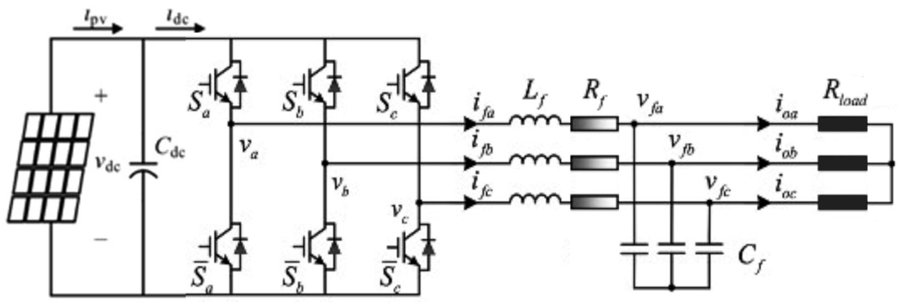
2. Predictive Model of the Single-Stage PV Inverter

The single-stage PV inverter system, as shown in Figure 1, is connected to the LVG or power load after the three-phase LC-filter and the GF voltage are established. The dynamic model on the AC side can be written as follows:
L f d i f d t = u n v f R f i f C f d v f d t = i f i o
The filter current if = [ia ib ic]T, the filter voltage vf = [va vb vc]T, and the output current io = [ioa iob ioc]T. The Lf, Cf, and Rf denote the inductance, capacitance, and resistance of the filter, respectively. The universal bridge output voltage of the inverter can be expressed as follows:
u n = N · s n · u p v
where
N = 1 3 2 1 1 1 2 1 1 1 2
and
s n = s a s b s c T
Sa, Sb, and Sc represent the switching states of the three-phase bridge arms, for example, 1 when the upper bridge arm is on and the lower bridge arm is off, and vice versa. Thus, there are eight possible switch combinations. In the traditional FCS-MPC for the PV sources inverter, only the inverter is modeled, and the characteristic of PV is rarely considered. In this study, a more precise predictive model of the PV inverter system is obtained. The PV array is connected to the inverter in parallel with the DC filter capacitor CPV. The dynamic model on the DC side can be expressed as follows:
C p v d u p v d t = i p v i d c
where idc = ifsn. By combining Equations (1)–(5) and applying Clarke transformation to the stationary αβ frame, the dynamic system model that contains the PV DC side can be written as follows:
X = A · X + B · U
where
X = i α i β v α     v β u p v T A = R f L f I 2 1 L f I 2 M · N · s n 1 C f I 2 0 2 x 2 0 2 x 1 9 4 C p v s n T · M T 0 1 x 2 0 B = 0 0 1 C f 1 C f 1 C p v T U = 0 0 i o α     i o β i p v T
where, iα, iβ, vα, vβ, i, and i are the components of if, vf, and io on the αβ axis; I2 is the identity matrix of order 2; 02x2, 02x1, and 01x2 are the zero matrix of the corresponding dimensions; and M is the coordinate transformation matrix, shown as follows:
M = 2 3 1 1 2 1 2 0       3 2 3 2
Based on the Euler approximation formula, the prediction model for the PV inverter with both DC-side and AC-side prediction functions can be constructed as follows:
X ( k + 1 ) = A d · X ( k ) + B d · U ( k )
where
A d = e A · T s , B d = 0 T s e A · τ · B d τ
where Ts denotes the sampling period. The eight switch states correspond to eight different sets of Ad and Bd, respectively. Each matrix can be precomputed offline and stored in memory. During real-time operation, the corresponding matrix is selected based on the chosen switch state to calculate the predicted values, ensuring minimal impact on the embedded controller’s real-time performance.

3. Proposed Grid-Forming Control Strategy

3.1. Proposed Modified Reference Desgin Under Different Operation

When the output power fails to meet the demand at MPP, the PV voltage is easily dropped into the uphill region and is finally prone to grid voltage collapse. This variability poses challenges for GF applications, especially without the integration of the ES. Thus, it is important to maintain the power balance between the DC side and AC side with proper regulation. In the conventional GF case, frequency regulation is often used to regulate the power balance.
However, the LVG has limited power supplies and low-voltage levels (typically under 400 V). The line impedance is primarily resistive, and changes in injected power are relatively insensitive to frequency changes. Conversely, adjusting the grid voltage offers a more practical alternative to impacting the source power injection into the LVG. Therefore, the regulation of the voltage amplitude is adopted as the control strategy to achieve power balance in this paper. For the PV inverter shown in Figure 1, the active power on the source side inject to the LVG can be expressed as follows:
P = ( V f V b u s · c o s δ ) · V f R
where Vf is denoted as inverter output voltage, Vbus is denoted as the voltage of the LVG, and δ is denoted as the difference of phase angle between Vf and Vbus.
In the downhill region, the variation of the PV voltage is extremely small, allowing for adjustable power margins and for operation in power reserve mode. Thus, the downhill region provides optimal DC voltage regulation conditions for GF control. For the multi-PV system, the droop control is commonly adapted to regulate the grid voltage and share the load among the multiple sources. In the predictive model, the grid voltage reference at the next sampling period can be obtained from the droop curve as follows:
V f * k + 1 = V * a I o ( k )
where V* is the nominal AC voltage, and a is the droop coefficient. The grid voltage reference in αβ frame can be designed as follows:
v α r e f ( k + 1 ) = ( V * a I o ( k ) ) cos 2 π f * T v β r e f ( k + 1 ) = ( V * a I o ( k ) ) sin 2 π f * T
For the single PV system, the grid voltage reference in the αβ frame can be designed as follows:
v α r e f ( k + 1 ) = V f * ( k + 1 ) cos 2 π f * T v β r e f ( k + 1 ) = V f * ( k + 1 ) sin 2 π f * T
where Vf*(k + 1) is denoted as a grid voltage reference of the LVG system in the next sampling period, and f* is denoted as the grid voltage frequency reference.
When the PV is operating in the MPP region, the PV inverter is operated in MPPT mode. The grid voltage reference at the next time can be designed as follows:
v α r e f ( k + 1 ) = V M P P * ( k + 1 ) cos 2 π f * T v β r e f ( k + 1 ) = V M P P * ( k + 1 ) sin 2 π f * T
where V*MPP is the reference grid voltage amplitude, which is obtained according to the AC and DC power balance of the inverter, shown as follows:
u p v · i p v = v a · i o a + v b · i o b
Thus, V*MPP can be designed as follows:
V M P P * = u P V M P P · i p v ( k ) i o a · cos 2 π f * T + i o b · s i n 2 π f * T
where u P V M P P is the reference voltage of the PV side in MPPT mode, which is obtained by the MPPT algorithm.
On the DC side, the designed grid voltage reference can indirectly achieve PV voltage stabilization and MPPT by balancing the power between the PV and grid load. By actively adjusting the voltage amplitude on the AC side, while keeping grid voltage frequency stable, the system ensures real-time power balance in the LVG. This adjustment maximizes power utilization during varying levels of low PV output.

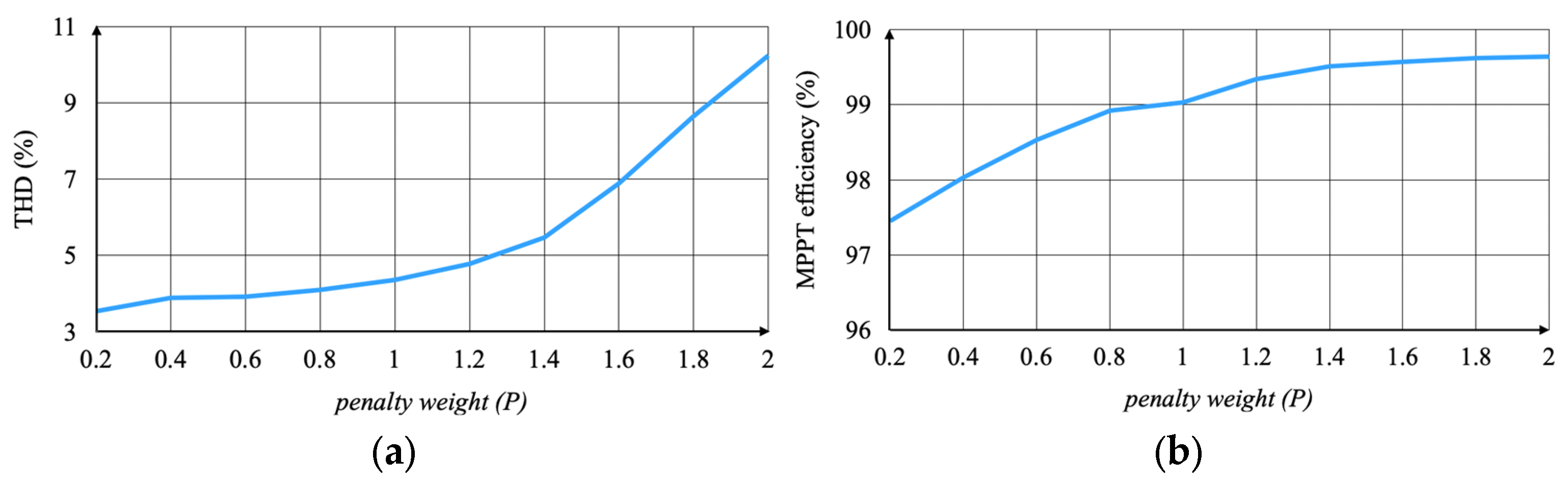
3.2. Proposed Modified Cost Function Under Different Operation

Traditionally, MPC strategies employ a cost function to quantify voltage tracking errors between predicted and reference values. When the PV operates in the downhill region, it is assumed that there is sufficient output power margin, ensuring that the reference voltage can be maintained. The cost function in the next control period G(k + 1) in the MPC of an inverter is generally designed as follows:
G k + 1 = v f α r e f k + 1 v f α k + 1 2 + [ v f β r e f k + 1 v f β ( k + 1 ) ] 2
where v f α , β r e f k + 1 represents the grid voltage reference in αβ frame, while v f α , β ( k + 1 ) is denoted as the inverter output voltage. The controller evaluates all possible switching states and selects the one that minimizes voltage tracking error, thereby ensuring optimal switching decisions.
When the PV operates in the uphill region, where u P V < u P V M P P , the system exhibits low damping, leading to reduced power output and compromised control efficiency. However, while certain switching states may obtain optimal AC-side control performance, they could simultaneously worsen the DC-side voltage performance. To address this, a modified cost function is introduced to balance the control demands of both the AC and DC sides. While a switching state deviates the PV operation point from the MPP region to the uphill region, the modified cost function G′(k + 1) is activated as follows:
G k + 1 = G k + 1 + P · [ u P V M P P u P V k + 1 ] ;     w h i l e   u P V < u P V M P P
Thereby, the PV voltage is guided towards to the MPP region. The penalty weight is controlled by the parameter P. Applying a higher A can provide an enhanced MPPT performance but sacrifice the AC-side voltage reference tracking precision.

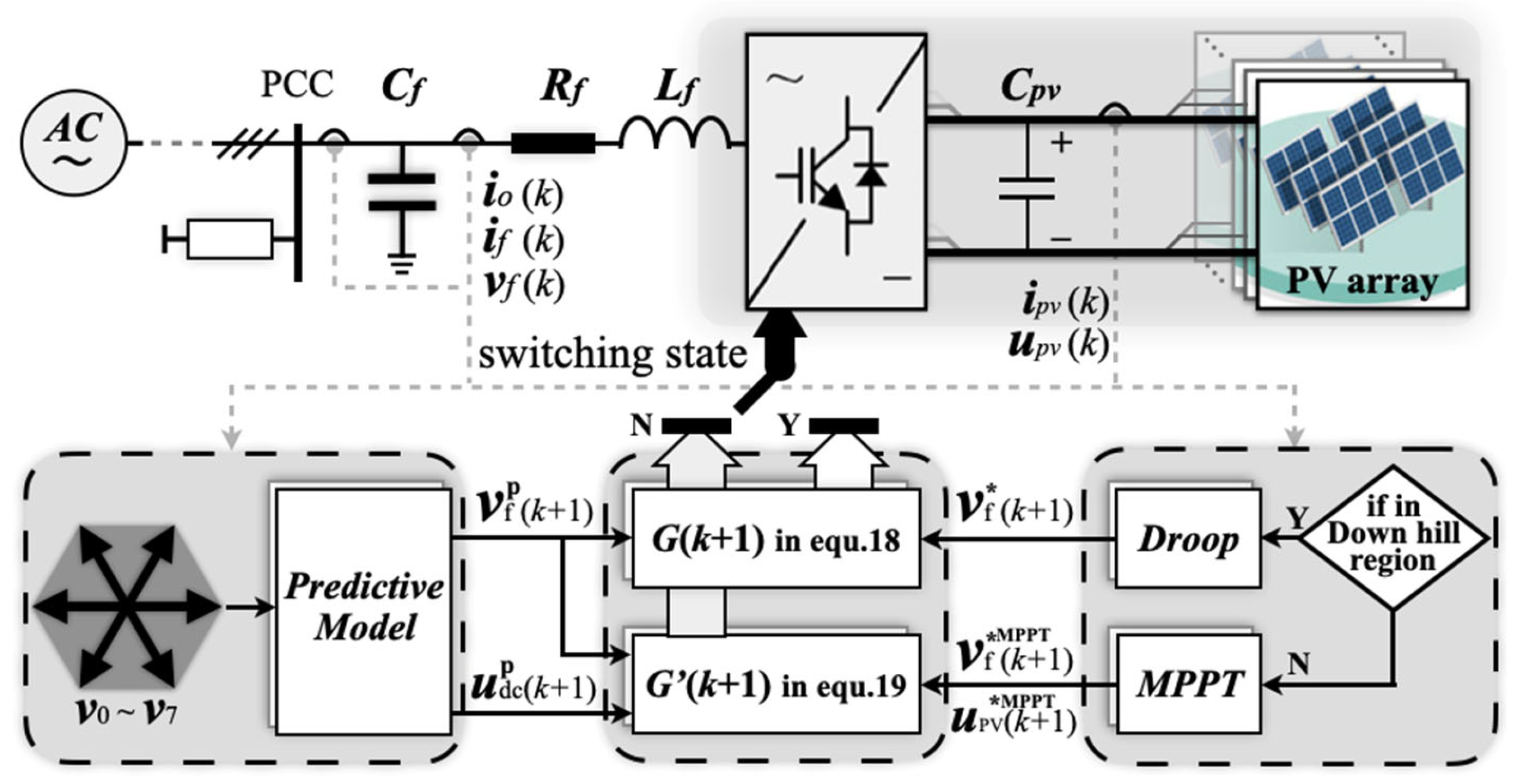
3.3. Proposed Controller

The overall control structure of the proposed GF scheme is illustrated in Figure 2. According to the conventional MPC framework, the filter voltage for the next control interval vfP(k + 1) can be predicted, while the predicted value of the DC-side voltage udcP(k + 1) is obtained via the modified predictive model. Depending on the incremental relationship between PV power and voltage, the droop controller is activated when the measured PV operating point enters the downhill region. Subsequently, an appropriate GF voltage reference vf*(k + 1) is provided to the cost function defined in Equation (18). Otherwise, a conventional perturb-and-observe method based on [29] is adopted and activated. In this case, the voltage reference is provided by MPPT block, and the DC-side MPP voltage is also provided for the proposed penalty term defined in Equation (19). The designed penalty term adjusts the DC-side voltage to the MPPT operating mode.
The single-stage PV system with the proposed GF control is capable of autonomously regulating the grid voltage. Specifically, when excess PV generation is available, the system operates in power reserve mode. Otherwise, when the PV output is insufficient to satisfy the load demand, the system will seamlessly transition to the MPPT mode to maximize power extraction.

4. Experimental Test Results

In this section, a test system comprising a single-stage PV inverter was developed to verify the effectiveness of the proposed method. In the simulation setup, PV sources and power loads were interconnected at the PCC. Various realistic operating scenarios, such as irradiation step changes due to passing clouds and the sudden fluctuation of the load, were taken into account to fully emulate practical operating conditions. Firstly, the control performance was evaluated using a simulation test on a single-PV inverter system. Subsequently, a GF regulation test considering multi-PV system operation was performed. Finally, a 2L-VSI controlled by TMS320F28377 was constructed and connected to the photovoltaic array simulator, and the proposed strategy was verified in hardware platform.
Before the test, the PV inverter was operated in the MPPT mode to investigate the optimal penalty weight. Figure 3 illustrates the variations of output voltage THD and MPPT efficiency under different penalty weights. As observed from Figure 3, the MPPT efficiency initially increases considerably with increasing penalty weight P and ultimately stabilizes at approximately 99.7% as P further rises. However, when the penalty weight exceeds 1.2, the output voltage THD begins to increase significantly, resulting in undesirable oscillations and high voltage ripple. Thus, considering an optimal trade-off between MPPT efficiency and voltage control precision, the penalty weight P is selected as 1 in the subsequent test analysis and discussion. The detailed parameters of the tested system model are summarized in Table 1.

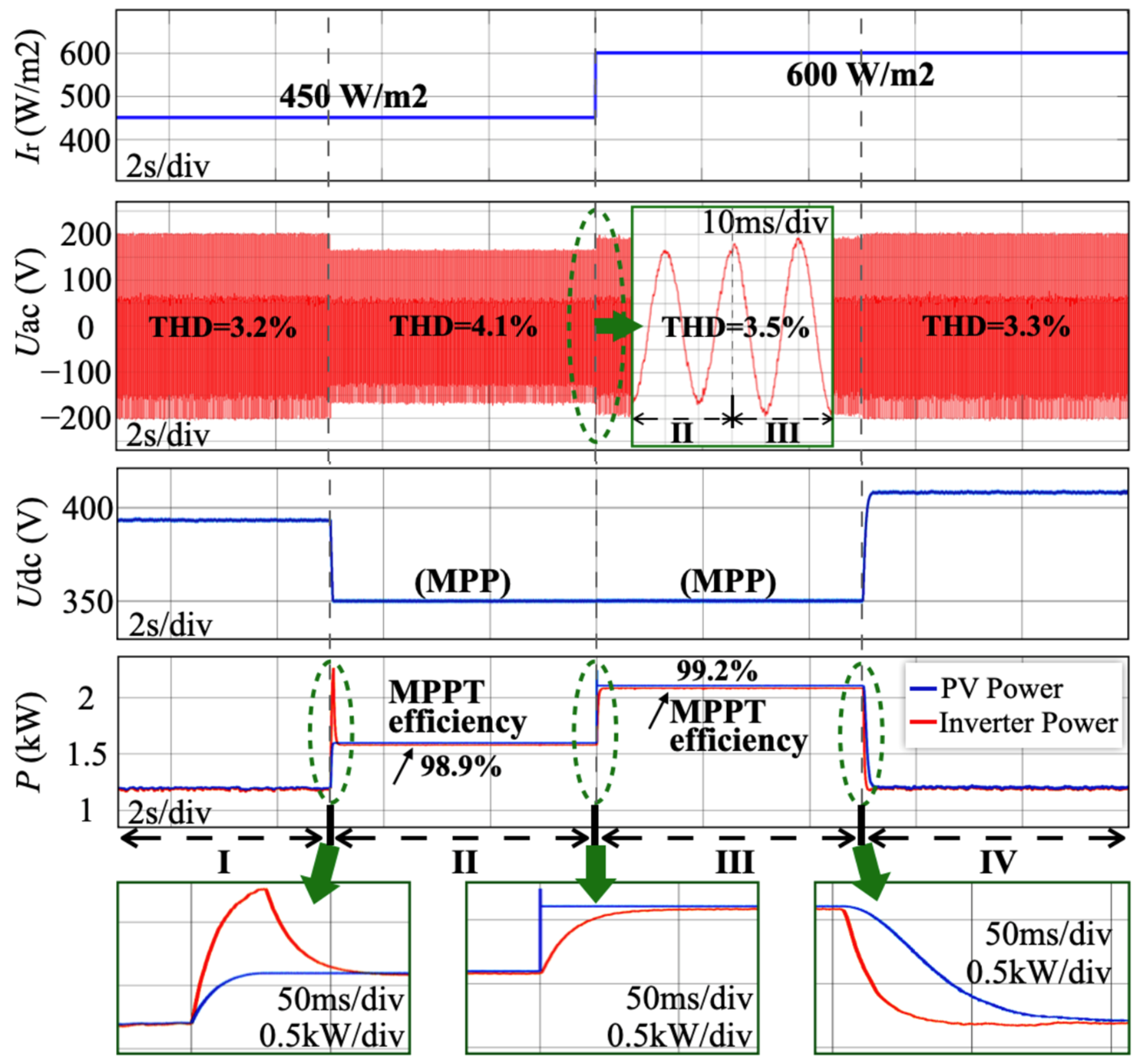
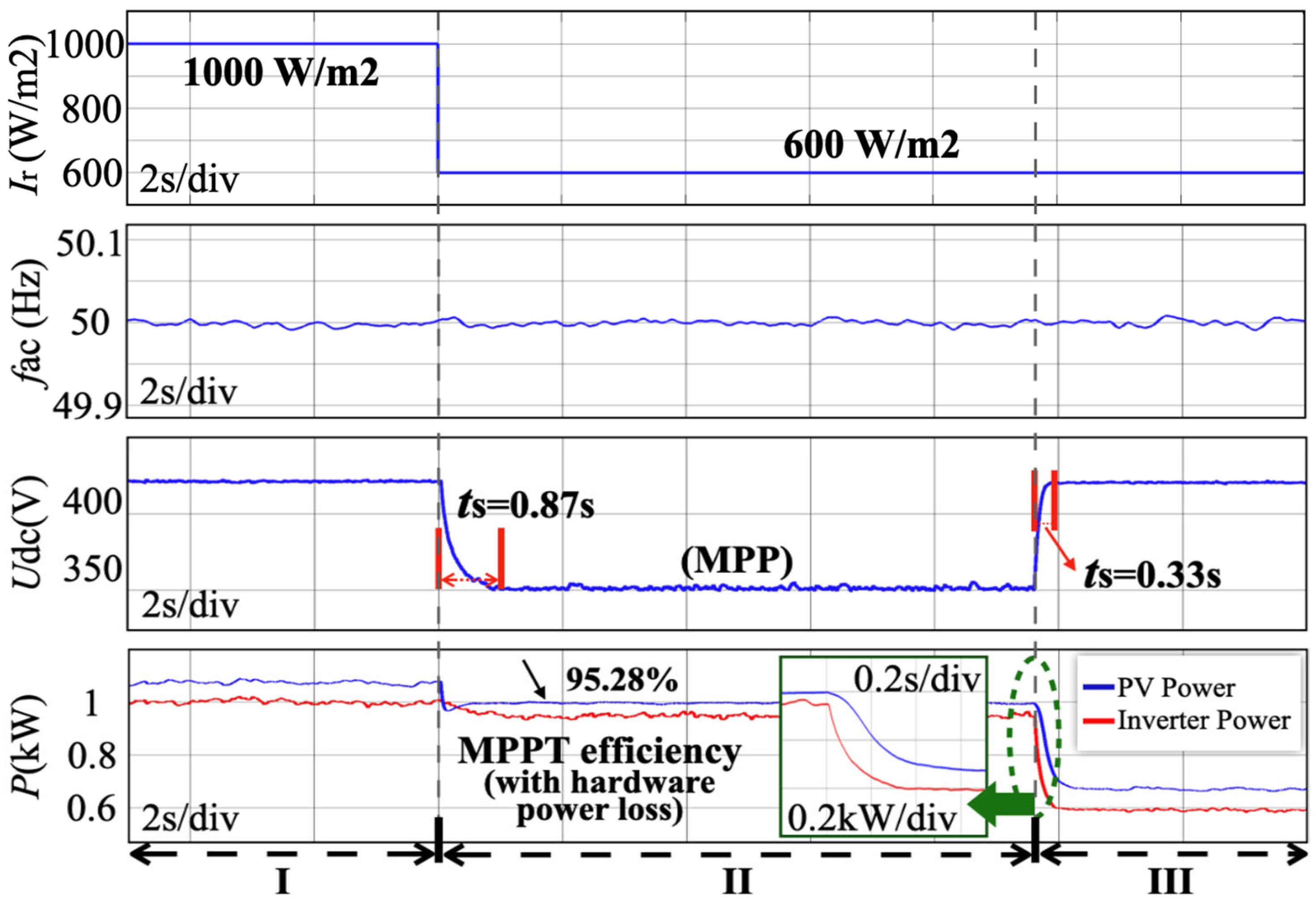
4.1. Dynamic Response to Irradiation and Load Change

Figure 4 demonstrates the dynamic response of the proposed control scheme under step changes in load and solar irradiation. Initially, in State I, the PV system supplied a nominal 1.2 kW load demand under solar irradiation of 450 W/m2. At the start of State II, when the nominal load demand instantaneously increased to 2.4 kW, the PV output voltage began to decrease as the controller actively adjusted system operation, quickly shifting from power reserve mode to MPPT mode to maximize power generation. Additionally, the output voltage reference was changed to provide a power balance instead of changing the frequency. Subsequently, in State III, the solar irradiation abruptly rose from 450 W/m2 to 600 W/m2. Although the available maximum power of the PV array was still below the nominal load demand, the grid voltage drop was effectively alleviated. In the final State IV, as the nominal load demand returned to 1.2 kW, the inverter swiftly returned to the reserve operation mode, promptly stabilizing output voltage back to its nominal reference.

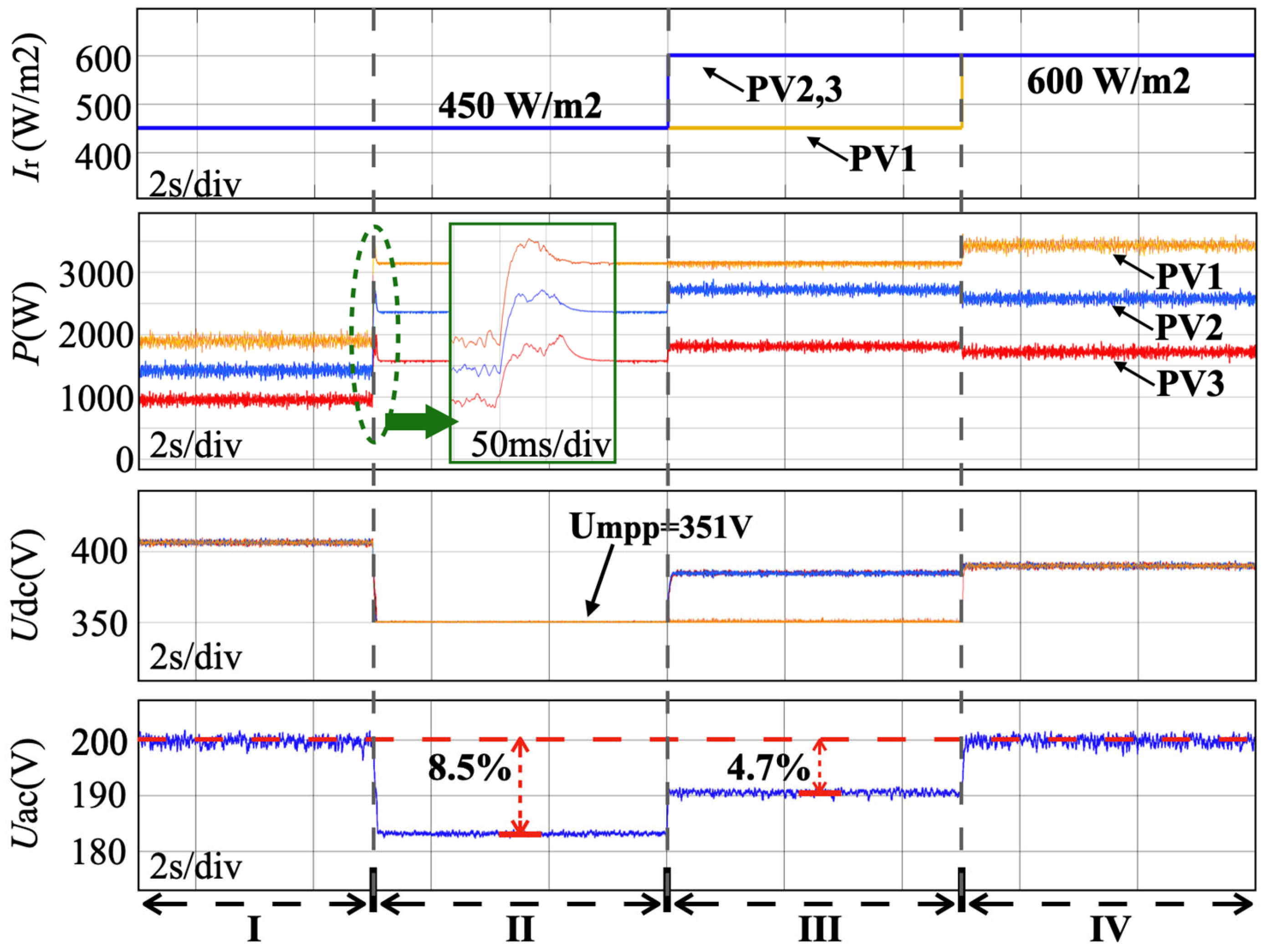
4.2. Multi-PV Sources Grid-Forming Regulation

To further verify the effectiveness of the proposed method under multi-PV source conditions, an LVG system consisting of three PV units was simulated. The nominal rated power outputs were proportionally set at ratios of 1:1.5:2, respectively. Correspondingly, the droop coefficients for the three PV sources were configured proportionally as 0.0125 V/W, 0.0083 V/W, and 0.00625 V/W, respectively. In the initial State I, both three PV sources were connected to regulate the AC-bus voltage under the same solar irradiation conditions at 450 W/m2. The nominal power demand was step changed from 4.35 kW to 8.7 kW in State II. In State III, the solar irradiation of PV2 and PV3 suddenly increased from 450 W/m2 to 600 W/m2. In State IV, the solar irradiations of PV1 increased from 450 W/m2 to 600 W/m2. The corresponding results are shown in Figure 5. In State I, as the PV power was sufficient to meet the nominal power demand, the three PV sources output the power proportionally and provided the nominal GF voltage. In State II, as the nominal power demand exceeded the available maximum power, the DC-side voltage dropped rapidly but was finally made stable into u P V M P P by the controller. Furthermore, the voltage reference was changed to maintain the power balance, resulting in an 8.5% voltage drop. In State III, the power output of PV2 and PV3 increased since its solar irradiation rose. Although the total power output of the PV sources was still not enough to maintain the AC-bus voltage, the voltage drop was alleviated to 4.7%. In State IV, with the solar irradiation changes in PV1, the total available maximum power was sufficient for the load demand, and the PV sources coordinately regulated the DC-bus voltage.
With the proposed control, the PV sources can regulate the AC-bus voltage when their available maximum power is sufficient. If the nominal power demand exceeds the total power output of the PV, the proposed control will track the MPP to compensate for the high load. The load can be shared proportionally according to the capacities of PV sources without communication links.

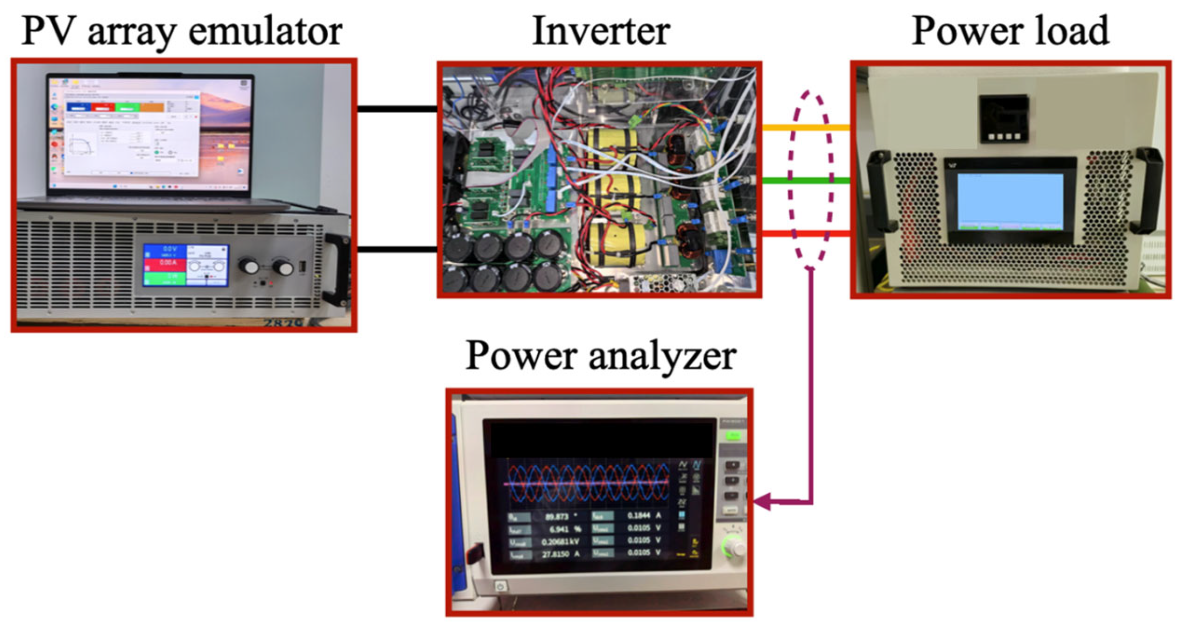
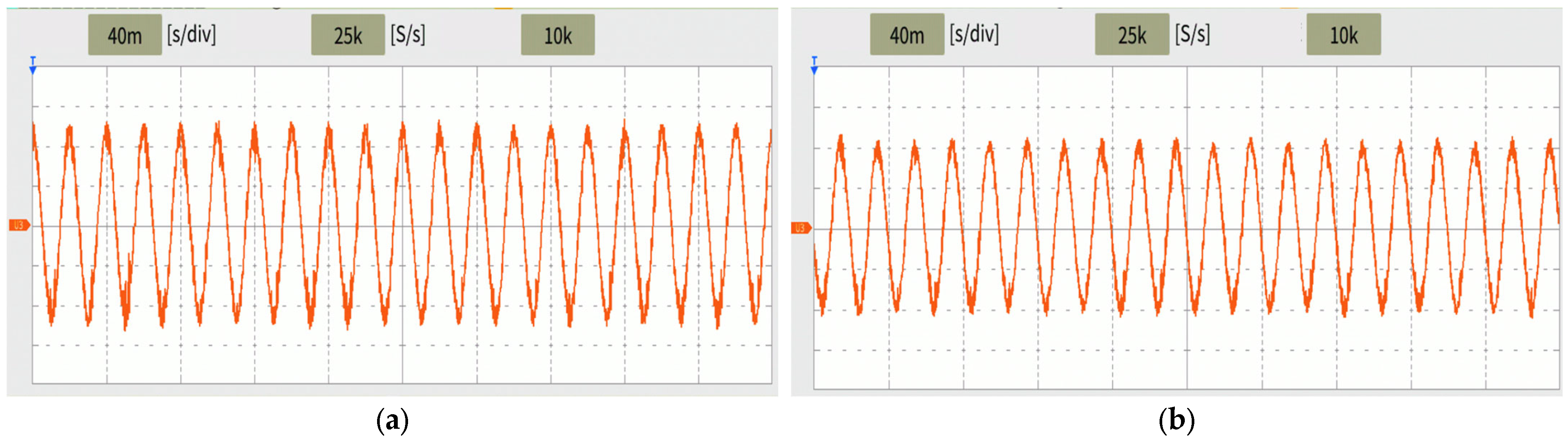
4.3. Hardware Experimental Verification

The proposed GF control for PV inverter was verified through a 2L-VSI and PV array emulator system. The system configuration of the experiment system is shown in Figure 6. Within the system, a TMS320F28377 digital signal processor was used for the strategy implementation. Nominal experimental parameters were chosen to be identical to those in simulation tests, as given in Table 1.
A test case investigating mode transition was conducted, with the corresponding waveforms captured in Figure 7. The power analyzer in Figure 6 recorded the following four key parameters: inverter output voltage frequency, PV voltage, PV power, and inverter power. In State I, the PV emulator initiated operation by supplying power to the circuits. In this state, the nominal power demand was set at 1 kW, and the PV was sufficient to support the load demand. The PV inverter system operated under power reserve mode, which can provide an output voltage with stable amplitude and frequency, as shown in Figure 7 and Figure 8a.
State II changed the irradiation setting of the PV emulator from 100% to 60% while maintaining the 1 kW nominal power demand. The PV voltage decreased rapidly as the system tried to increase power output. In this case, the controller switched to MPPT mode almost simultaneously and tracked the maximum power. However, the available maximum power remained insufficient to meet the demand, resulting in a voltage drop to maintain power balance, as shown in Figure 8b. In State III, the nominal power demand was reduced to 0.6 kW, which was below the PV maximum output capacity. The controller successfully reverted to power reserve mode, in this case, with rapid response characteristics.

5. Conclusions

This paper proposes a comprehensive GF control strategy for single-stage PV inverters, addressing both steady-state operation and dynamic-state transitions. The single-stage PV system with the proposed GF control strategy can autonomously regulate the grid voltage to achieve power reserve mode when excess PV power is available, and seamlessly switch to MPPT mode when PV output is insufficient to meet load demand. Furthermore, with the proposed strategy, the load power is fairly shared under multi-PV source operation, without the need for an ES system. Future research will expand experimental validation to include fault scenario performance assessments and explore MPC implementations for GF operation without MPP estimation requirements.

Author Contributions

Conceptualization, X.Z., P.Y. and W.W.; Methodology, X.Z., P.Y. and H.C.; Software, X.Z. and J.L.; Validation, X.Z., P.Y. and H.C.; Formal analysis, X.Z., Y.X. and W.W.; Investigation, X.Z. and W.W.; Resources, J.L.; Writing—original draft, X.Z.; Writing—review & editing, X.Z.; Project administration, W.W. All authors have read and agreed to the published version of the manuscript.

Funding

This work was supported by the Smart Grid-National Science and Technology Major Project under Grant 2024ZD0800300.

Institutional Review Board Statement

Not applicable.

Informed Consent Statement

Not applicable.

Data Availability Statement

The original contributions presented in this study are included in the article. Further inquiries can be directed to the corresponding author.

Conflicts of Interest

The authors declare no conflict of interest.

References

  1. Rathnayake, D.B.; Akrami, M.; Phurailatpam, C.; Me, S.P.; Hadavi, S.; Jayasinghe, G.; Zabihi, S.; Bahrani, B. Grid forming inverter modeling, control, and applications. IEEE Access 2021, 9, 114781–114807. [Google Scholar] [CrossRef]
  2. Yan, W.; Shah, S.; Gevorgian, V.; Koralewicz, P.; Wallen, R.; Gao, D.W. On the Low Risk of SSR in Type III Wind Turbines Operating With Grid-Forming Control. IEEE Trans. Sustain. Energy 2024, 15, 443–453. [Google Scholar] [CrossRef]
  3. Tehrani, K.; Simde, D.; Fozing, J.; Jamshidi, M. A 3D Design of Small Hybrid Farm for Microgrids. In Proceedings of the 2022 World Automation Congress (WAC), San Antonio, TX, USA, 11–15 October 2022; pp. 1–6. [Google Scholar]
  4. Hernandez, J.C.; Bueno, P.G.; Sanchez-Sutil, F. Enhanced utilityscale photovoltaic units with frequency support functions and dynamic grid support for transmission systems. IET Renew. Power Gener. 2017, 11, 361–372. [Google Scholar] [CrossRef]
  5. Lu, S.; Xu, Z.; Xiao, L.; Jiang, W.; Bie, X. Evaluation and enhancement of control strategies for VSC stations under weak grid strengths. IEEE Trans. Power Syst. 2017, 33, 1836–1847. [Google Scholar] [CrossRef]
  6. Rosso, R.; Engelken, S.; Liserre, M. Robust stability investigation of the interactions among grid-forming and grid-following converters. IEEE J. Emerg. Sel. Top. Power Electron. 2020, 8, 991–1003. [Google Scholar] [CrossRef]
  7. Sun, D.; Liu, H.; Gao, S.; Wu, L.; Song, P.; Wang, X. Comparison of different virtual inertia control methods for inverter-based generators. J. Modern. Power Syst. Clean Energy 2020, 8, 768–777. [Google Scholar] [CrossRef]
  8. Lin, Y.; Eto, J.H.; Johnson, B.B.; Flicker, J.D.; Lasseter, R.H.; Pico, H.N.V.; Seo, G.-S.; Pierre, B.J.; Ellis, A. Research Roadmap on Grid-Forming Inverters; National Renewable Energy Lab (NREL): Golden, CO, USA, 2020; Volume 1, pp. 1–60. [Google Scholar]
  9. Tayyebi, A.; Groß, D.; Anta, A.; Kupzog, F.; Dörfler, F. Frequency stability of synchronous machines and grid-forming power converters. IEEE Trans. Emerg. Sel. Top. Power Electron. 2020, 8, 1004–1018. [Google Scholar] [CrossRef]
  10. Pattabiraman, D.; Lasseter, R.H.; Jahns, T.M. Comparison of grid following and grid forming control for a high inverter penetration power system. In Proceedings of the IEEE PESGM, Portland, OR, USA, 5–10 August 2018; pp. 1–5. [Google Scholar]
  11. Pawar, B.; Batzelis, E.I.; Chakrabarti, S.; Pal, B.C. Grid-forming control for solar PV systems with power reserves. IEEE Trans. Sustain. Energy 2021, 12, 1947–1959. [Google Scholar] [CrossRef]
  12. Guo, Z.; Li, K.-J.; Liu, Z.; Li, J.; Song, Y. Reserch on Model Predictive Control-Based Single-Stage Photovoltaic System During Grid. In Proceedings of the 2023 IEEE Industry Applications Society Annual Meeting (IAS), Nashville, TN, USA, 29 October–2 November 2023. [Google Scholar]
  13. Chen, Z.; Lasseter, R.H.; Jahns, T.M. Power reserve for grid-forming PV sources with stability enhancement in mixed-source microgrids. In Proceedings of the IEEE PESGM, Atlanta, GA, USA, 4–8 August 2019; pp. 1–5. [Google Scholar]
  14. Rasoanarivo, I.; Tehrani, K.; Scalcon, F.P.; Nahid-Mobarakeh, B. A Dual Multilevel Adaptive Converter for Microgrid Applications. In Proceedings of the IECON 2022—48th Annual Conference of the IEEE Industrial Electronics Society, Brussels, Belgium, 17–20 October 2022; pp. 1–6. [Google Scholar]
  15. Elkhatib, M.E.; Du, W.; Lasseter, R.H. Evaluation of inverter-based grid frequency support using frequency-watt and grid-forming PV inverters. In Proceedings of the IEEE PESGM, Portland, OR, USA, 5–10 August 2018; pp. 1–5. [Google Scholar]
  16. Lasseter, R.H.; Chen, Z.; Pattabiraman, D. Grid-forming inverters: A critical asset for the power grid. IEEE Trans. Emerg. Sel. Top. Power Electron. 2019, 8, 925–935. [Google Scholar] [CrossRef]
  17. Ding, L.; Xue, N.; Qu, Z. Grid-forming Control of Single- and Two-Stage Solar PV Systems with Mode Transition. In Proceedings of the 2023 IEEE Applied Power Electronics Conference and Exposition (APEC), Orlando, FL, USA, 19–23 March 2023; pp. 960–965. [Google Scholar]
  18. Yang, P.; Xia, Y.; Yu, M.; Wei, W.; Peng, Y. A Decentralized Coordination Control Method for Parallel Bidirectional Power Converters in a Hybrid AC–DC Microgrid. IEEE Trans. Ind. Electron. 2018, 65, 6217–6228. [Google Scholar] [CrossRef]
  19. Yang, P.; Peng, Y.; Xia, Y.; Wei, W.; Yu, M.; Feng, Q. A unified bus voltage regulation and MPPT control for multiple PV sources based on modified MPC in the DC microgrid. Front. Energy Res. 2022, 10, 1010425. [Google Scholar] [CrossRef]
  20. Liu, T.; Chen, A.; Qin, C.; Chen, J.; Li, X. Double vector model predictive control to reduce common-mode voltage without weighting factors for three-level inverters. IEEE Trans. Ind. Electron. 2020, 67, 8980–8990. [Google Scholar] [CrossRef]
  21. Pawar, B.; Chakrabarti, S.; Batzelis, E.I.; Pal, B.C. Grid-Forming Control for Solar PV Systems with Real-Time MPP Estimation. In Proceedings of the 2021 IEEE Power & Energy Society General Meeting (PESGM), Washington, DC, USA, 26–29 July 2021; pp. 1–5. [Google Scholar]
  22. Batzelis, E.I.; Junyent-Ferre, A.; Pal, B.C. MPP Estimation of PV Systems keeping Power Reserves under Fast Irradiance Changes. In Proceedings of the 2020 IEEE Power & Energy Society General Meeting (PESGM), Montreal, QC, Canada, 2–6 August 2020; pp. 1–5. [Google Scholar]
  23. Katyal, A.; Pathak, D.; Gaur, P. Smart MPPT Approach using Prominent Metaheuristic Algorithms for Solar PV Panel. In Proceedings of the 2022 IEEE Delhi Section Conference (DELCON), New Delhi, India, 11–13 February 2022; pp. 1–11. [Google Scholar]
  24. Kouro, S.; Cortes, P.; Vargas, R.; Ammann, U.; Rodriguez, J. Model Predictive Control—A Simple and Powerful Method to Control Power Converters. IEEE Trans. Ind. Electron. 2009, 56, 1826–1838. [Google Scholar] [CrossRef]
  25. Zeng, Z.; Chen, D.; Qin, S.; Yuan, S.; Zou, Z.; Chen, J.; Qi, C. A Model Predictive Control With Grid-Forming Capability for Back-to-Back Converters in Wind Turbine Systems. IEEE Open J. Power Electron. 2024, 5, 1697–1708. [Google Scholar] [CrossRef]
  26. Vanti, S.; Bana, P.R.; D’Arco, S.; Amin, M. Single-Stage Grid-Connected PV System With Finite Control Set Model Predictive Control and an Improved Maximum Power Point Tracking. IEEE Trans. Sustain. Energy 2022, 13, 791–802. [Google Scholar] [CrossRef]
  27. Vanti, S.; Bana, P.R.; Amin, M. Single-stage PV System With Multi-Objective Predictive Control Approach. In Proceedings of the IECON 2021—47th Annual Conference of the IEEE Industrial Electronics Society, Toronto, ON, Canada, 13–16 October 2021; pp. 1–6. [Google Scholar]
  28. Shan, Y.; Hu, J.; Li, Z.; Guerrero, J.M. A Model Predictive Control for Renewable Energy Based AC Microgrids Without Any PID Regulators. IEEE Trans. Power Electron. 2018, 33, 9122–9126. [Google Scholar] [CrossRef]
  29. Esram, T.; Chapman, P.L. Comparison of photovoltaic array maximum power point tracking techniques. IEEE Trans. Energy Convers. 2007, 22, 439–449. [Google Scholar] [CrossRef]
Figure 1. Single-stage PV inverter.
Sustainability 17 05227 g001
Figure 2. Controller design of the proposed strategy.
Sustainability 17 05227 g002
Figure 3. Influence of penalty weight variation on (a) voltage THD and (b) MPPT efficiency.
Sustainability 17 05227 g003
Figure 4. Simulation test results of single-PV system under condition changes.
Sustainability 17 05227 g004
Figure 5. Simulation test results of multi-PV source system with grid-forming regulation.
Sustainability 17 05227 g005
Figure 6. Experimental environment.
Sustainability 17 05227 g006
Figure 7. Hardware experiment results containing inverter output voltage frequency, PV voltage, PV power, and inverter power.
Sustainability 17 05227 g007
Figure 8. Hardware experiment results: (a) inverter output voltage under power reserve mode in State I; (b) inverter output voltage under MPPT mode in State II.
Sustainability 17 05227 g008
Table 1. System parameters.
ParameterSymbolValue
inverter filter inductanceLf3 mH
inverter filter capacitanceCf20 µF
inverter filter resistanceRf0.2 Ω
penalty weightP1
PV-side capacitorCpv1360 µF
switching frequencyfsw20 kHz
grid-forming voltage v f r e f 200 V/50 Hz
Disclaimer/Publisher’s Note: The statements, opinions and data contained in all publications are solely those of the individual author(s) and contributor(s) and not of MDPI and/or the editor(s). MDPI and/or the editor(s) disclaim responsibility for any injury to people or property resulting from any ideas, methods, instructions or products referred to in the content.

