1. Introduction
Unmanned aerial vehicles (UAVs) are becoming a major part of the civil and military aviation industries. They belong to a group of aircraft designed to perform missions without an onboard crew. They can be piloted remotely (including from the ground, air, or ship) or perform the mission automatically, or even autonomously. UAVs are designed to return to the take-off/landing site and be reused, but they can also be treated as disposable flying devices.
UAVs have gained significant interest because they can meet user needs for effective supply transportation and the real-time acquisition of accurate information during air operations [
1,
2]. They are mainly used to detect potential threats and, at a later stage, enable appropriate responses by a remote pilot or an autonomous system. Sometimes, there is a need to use an aircraft with the smallest dimensions possible to reach particularly inaccessible and/or dangerous places [
2]. In general, unmanned systems with integrated EO/IR cameras and active/passive sensors may be used for the following [
3]:
Inspection and monitoring: Traffic monitoring, such as roads and traffic conditions, information transfer, traffic estimation [
4]; vehicle tracking and traffic management based on collected data processing [
5,
6]; infrastructure inspection and monitoring, such as the automated inspection of big buildings, cell towers, grid power lines and transformers, as well as water, gas, and oil pipelines based on video capture analysis [
7,
8,
9,
10]; power plant and nuclear reactor inspection [
11]; environmental monitoring (volcano state monitoring; water resource monitoring before, during, and after floods); CO, CO
2, SO
2, and NO
2 gas pollution monitoring [
12,
13]; and fire surveillance [
14]);
Delivery (the fast delivery of goods or packages [
15,
16,
17]);
Agriculture (crop irrigation, low-altitude high-precision imaging for crop statuses and health estimation, disease and weed detection, and residue cover [
18,
19,
20,
21,
22]);
Urban air mobility (new opportunities for on-demand, safe, sustainable, affordable, and accessible air transportation systems for passenger mobility, goods delivery, and emergency services within or traversing metropolitan areas [
23,
24,
25]);
Military applications (land and naval artillery fire guidance, delivery of equipment and supplies, radio and data relay, border surveillance, reconnaissance and spy missions, communication disruption, electronic warfare, and anti-missile defense).
UAV structures often vary widely in their configurations depending on the platform and mission. Many different classifications of UAVs may be made based on different features. Rising operational demands have forced design engineers and manufacturers to take steps to increase the flight endurance and payload of UAVs, resulting in various UAV configurations with different sizes, endurance levels, and capabilities. Unmanned aerial vehicle platforms may be divided into the following four categories [
1,
2,
15]:
Fixed-wing UAVs—unmanned airplanes (with wings) that require a runway for take-off and landing (or catapult launching). In general, they have long endurance and can fly at high cruising speeds.
Rotary-wing UAVs—also called rotorcraft UAVs or vertical take-off and landing (VTOL) UAVs. They have hovering capabilities and high maneuverability.
Blimps (balloons and airships)—lighter-than-air aircraft. They have long endurance but fly at low speeds and are usually large in size.
Flapping-wing UAVs—generally small structures with flexible and/or morphing small wings inspired by birds and flying insects.
Another classification of UAV platforms considers the size/weight and endurance criteria [
1,
2,
15]:
Class I(a)—weight < 0.2 kg—Nano UAV;
Class I(b)—weight in the range of 0.2 kg to 2 kg—Micro UAV;
Class I(c)—weight in the range of 2 kg to 20 kg—Mini UAV;
Class I(d)—weight in the range of 20 kg to 150 kg—Small UAV;
Class II—weight in the range of 150 kg to 600 kg—Tactical UAV;
Class III(a)—weight > 600 kg—Medium Altitude Long Endurance (MALE) UAV;
Class III(b)—weight > 600 kg—High Altitude Long Endurance (HALE) UAV;
Class III(c)—weight > 600 kg—Strike/Combat UAV.
As shown above, the main requirements for Class III UAVs are the flight altitude and operational flight time. Therefore, it should be no surprise that gas turbine engines are commonly selected as aircraft propulsion systems due to their high power-to-weight ratios and long flight times. However, they are not suited for small-scale UAVs because mini and micro gas turbines produce higher noise levels, which limits their silent operations, and have low fuel economy, which, in turn, shortens the operational flight time.
On the other hand, most of the small, mini, and micro UAVs currently available on the market are electrically driven since they originate from hobby modeling. Brushed and Brushless Direct Current (DC) Electric Motors (EMs) are low-cost, dust-proof, and have low thermal and acoustic signatures. Electronic control systems allow for an easy adaptation to automatic control. They produce no pollutant emissions and have high reliability, which minimizes the possibility of crashes or failures. The biggest disadvantage of this solution is the short flight time resulting from the relatively low energy density of the cells used in onboard batteries. Even commonly used lithium-ion cells (Li-Ion) have an energy density that is several dozen times lower than that contained in gasoline.
Recently, the problem of greenhouse gas (GHG) emissions has increased due to the use and depletion of fossil fuels, which has led to a decrease in interest in the utilization of combustion engines and shifted attention to the broader use of electric propulsion as a green technology in different sectors, including transportation. This trend may eliminate ICE engines in UAVs when the need for long endurance is irrelevant.
Therefore, the possibility of extending the operation flight time is very much needed. In terms of operations, increased endurance shortens or even eliminates the time needed to fly from the launch site to the mission zone and return to the landing site. Such advantages are provided by the use of hybrid propulsion. A hybrid electric propulsion system (HEPS) for UAVs is a good solution that combines the benefits of both thermal and electric engines into a hybrid architecture.
The relatively high energy density of gasoline allows the construction of an electric power supply system that provides the necessary amount of electrical energy based on an ICE engine and a generator. Despite the low efficiency of the ICE engine and its large mass together with the generator, the mass of the gasoline reserve in the onboard tank, with a smaller mass than the mass of the battery, allows for a flight with the same duration. It should also be noted that the mass of such a system decreases with the consumption of fuel in the tank, which reduces the current demand for energy and allows for a longer flight.
2. Case Study
Since this article is focused on modeling a digital twin for a hybrid electric propulsion system dedicated to multi-rotor aerial vehicles with a Maximum Take-Off Weight (MTOW) of 25 kg and onboard electric voltage of 44.4 V (12S Li-Ion/Li-Poly battery), further analyses will concern this specific platform category.
In the group of hybrid electric drive systems for both automotive and UAVs, two main types of architecture can be distinguished [
26,
27,
28], resulting from the method of connecting the ICE engine with an electric generator to the onboard power bus (the “red” lines stand for mechanical and the ”green” arrows for electrical connection):
Parallel hybrid power system (
Figure 2).
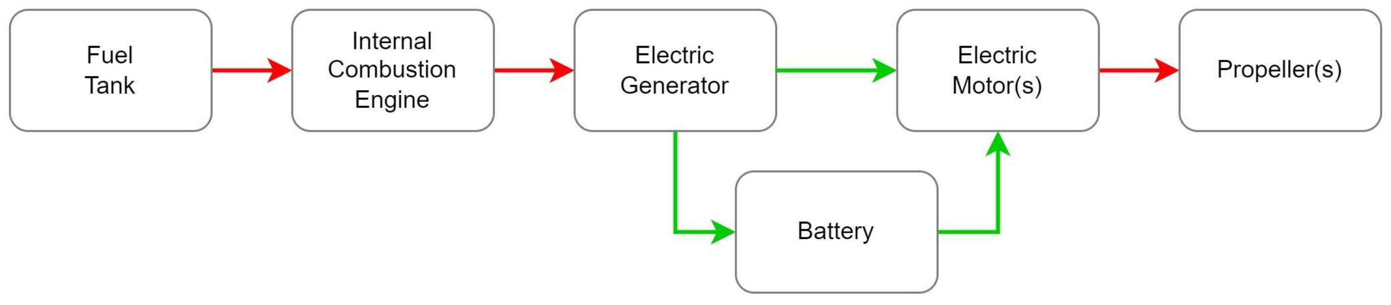
In a series system (
Figure 1), the combustion engine is not directly mechanically connected to the drive system; it can always operate at its optimal operating point (rotational speed and torque at which fuel consumption is the lowest in relation to the power delivered). In the case of a multi-rotor UAV, an additional advantage is the simplicity of transferring the drive to individual propellers. It is enough to mount one combustion engine near the center of the mass of the UAV, which supplies electrical energy via electrical cables to the BLDC motors placed on the arms.
The disadvantage of the series solution is the reduced reliability of the system. It is necessary to convert the energy of rotational motion into electrical energy and then reconvert the electrical energy back to rotational motion energy. This means that a failure of one of the elements in the series connection is enough to make it impossible to supply energy from the combustion engine. In addition, the conversion of energy in the system results in increased power losses.
The advantage of the parallel architecture (
Figure 2) is greater reliability due to the fact that both the electric and combustion engines can independently drive the UAV. Additionally, they can secure the power supply in the event of a temporary increase in power demand. There is no need to use an additional generator because the electric motor can work as a generator if the UAV is currently powered by energy from the combustion engine.
The disadvantage of the parallel system is a more complicated drive system than in the case of the series architecture. It is necessary to ensure the possibility of disconnecting the combustion engine when the UAV is powered by the electric motor so that it does not constitute an unnecessary load. Similarly, when the UAV is powered only by the combustion engine and the battery is fully charged, the electric motor should be disconnected. Direct supply of rotational energy from the combustion engine to the drive system means fewer possibilities for optimizing the operating point of this engine because its rotational speed cannot be freely changed.
Below, several commercial solutions for hybrid electric power generators for unmanned aerial vehicles are presented.
2.1. Richen Power H2 UAV Generator
The Richen Power (Beijing, China) H2 UAV Generator [
29] has a total weight of 5.2 kg, including accessories. According to the manufacturer, it is capable of delivering 1.8 kW of continuous power and 2.0 kW of instantaneous power, consuming 0.750 kg of gasoline with an octane number above 95 for each kilowatt-hour of energy generated. Its generator produces a voltage of about 49 V. It is dedicated to powering UAVs with a maximum take-off weight of 18 kg. Available accessories include a fuel level sensor, a control system, and a battery providing power (according to the manufacturer) for 90 s for an emergency landing in the event of engine failure. The control system provides access to information on the system’s status and errors. According to the documentation, the H2 UAV Generator requires manual operation at each take-off.
2.2. Richen Power H2 Plus UAV Generator
The H2 Plus UAV Generator [
30] is a developed version of the H2 UAV Generator, which, compared to the original, is able to provide 33% more continuous power, equal to about 2.4 kW, with an empty weight of 5.6 kg. According to the manufacturer’s declaration, it is suitable for powering UAVs with a MTOW of 25 kg. Compared to the H2, it is slightly larger in terms of dimensions. Other parameters, such as the fuel consumption per kilowatt-hour of energy produced, permissible operating temperature, fuel type, and generator output voltage, remain unchanged.
2.3. Sky Power GmbH SP 55 TS GEN
The Sky Power GmbH (Bad Homburg, Germany) SP 55 TS GEN generator [
31] is a fusion of the SP 55 ICE engine and SG 080 generator. A combustion engine is a single-cylinder engine with a capacity of 55 cm
3 and a power of 3.1 kW, equipped with an advanced control system for its operation. The electric generator is responsible for the production of electricity in the SP 55TS GEN drive, which is also used as a starting system for the ICE engine. The SP 55 TS GEN engine-generator system is capable of delivering an electrical power of approximately 1.92 kW with a fuel consumption of approximately 0.530 kg of fuel per kilowatt-hour.
2.4. Pegasus Aeronautics GE 35 Range Extender
The Pegasus Aeronautics (Waterloo, ON, Canada) GE 35 [
32] is a hybrid drive equipped with a single-cylinder liquid-cooled combustion engine with a capacity of 35 cm
3, together with a generator with a power of 2.0 kW and an output voltage adjustable in the range of 24 ÷ 50 V. According to the manufacturer, the mass of the unit without fuel and coolant is 2.6 kg. The system can communicate with the autopilot via the CAN bus or duplicated (redundant) PWM signals. The controller provides automatic control of the rotational speed depending on the generator load, and it can also start the engine without additional equipment. Therefore, it also allows for the control of the charge state of the UAV’s onboard battery.
2.5. Pegasus Aeronautics GE 70 Range Extender
The GE 70 [
33] is a hybrid drive to power UAVs with a MTOW of approximately 25 kg that require higher electrical energy. Compared to the GE 35, the displacement has been increased to 70 cm
3 (two liquid-cooled cylinders). The maximum output power of the generator is about 4.0 kW, with an output voltage regulated in the range of 24 ÷ 50 V. Increasing the specifications of the combustion unit and generator resulted in a higher weight of the “dry” engine (without fuel and coolant), reaching 3.5 kg. Similar to the GE 35, the GE 70 also uses automatic control of the fuel supply to the engine based on the load, capability for independent and automatic startup, and communication using the CAN/PWM interface standard.
2.6. SVFFI FLY 3600
The SVFFI (Zhuhai City, China) FLY 3600 hybrid drive is a high-performance generator dedicated to multi-rotor UAVs with a MTOW of up to 31 kg, enabling flights lasting up to about 3 h. The weight of the hybrid generator is 5.7 kg, and the continuous output power is 2.9 kW at a voltage of 44.4 V. The maximum output power is 3.6 kW. The generator also requires a 12S Li-Po onboard battery, which provides an additional portion of electrical energy, supporting the generator during rapid ascent or rapid maneuvers. The generator is powered by a mixture of 95-octane gasoline (or higher) with lubricating oil dedicated to two-stroke combustion engines. The integrated system for starting and generating electrical power, as well as compressed-air starting, can be implemented without the need for additional equipment. The emergency battery supports UAV maneuvers such as landings and/or emergency landings.
2.7. SVFFI FL 6000
The FL 6000 hybrid drive is a development version of the FLY 3600 generator, designed for multi-rotor UAVs with a MTOW of up to 49 kg, enabling flights lasting up to about 2 h. The mass of the hybrid generator is 7.2 kg, and the continuous output power is about 5.0 kW at a voltage of 44.4 V. The maximum output power is 6.0 kW. A 12S Li-Po onboard battery is required for its operation, which provides additional electrical energy and supports the system during rapid ascent or maneuvers. The generator is powered by a mixture of 95-octane gasoline (or higher) with lubricating oil dedicated to two-stroke combustion engines. The integrated system for starting and generating electrical power, as well as compressed-air starting, can be implemented without the need for additional equipment. The emergency battery supports UAV maneuvers such as landings and/or emergency landings.
3. Materials and Methods
3.1. Hybrid Electric Propulsion System Assumptions
The long-term target for this work is to build a prototype of a hybrid electric propulsion system dedicated to a multi-rotor unmanned aerial vehicle with a MTOW of 25 kg and onboard electric voltage of 44.4 V. The given MTOW is dictated by civil aviation regulations, which allow the operation of UAVs weighing up to 25 kg in open airspace, provided the operator has the required knowledge, training, and certificates. The onboard voltage of 44.4 V results from the power required for flight and reflects the principle that the higher the voltage, the lower the current. The currently offered agricultural UAVs used for crop monitoring, watering, and fertilization are driven by ICE engines and are called “hybrid”, even though the combustion engine operates throughout the entire airborne operation, with a small 12S Li-Ion battery serving as a backup for a safe landing in case the ICE engine fails. Some of the commercial hybrid drive solutions listed in the previous chapter allow for remote start/stop functionality or even require manual startup by maintenance personnel.
A literature review revealed some research focused on modeling a hybrid electric drive for light unmanned aircraft [
34,
35,
36]. One research team [
37] undertook the challenge of building a prototype HEPS based on “off-the-shelf” components. Based on the research conducted on current commercial solutions, state-of-the-art knowledge, and known efforts of other research centers—as well as the defined requirements—the main components were identified, and the assumptions were established to describe the functioning of a designed HEPS and its equivalent digital twin, which will resemble the classic hybrid drive known from the automotive sector.
The main components of a HEPS are as follows:
ICE Generator (an ICE engine connected via a spring clutch to a BLDC generator, which will also serve as an electric starter);
Energy converter (rectifier bridge with a voltage and current regulator);
Main battery;
Main battery charge and discharge system (control of individual cell voltages);
Monitor and control unit with original software (this controls the combustion generator, measures operational parameters, and manages normal and emergency states).
Assumptions for HEPS operation:
Series hybrid power system architecture;
The ICE Generator will operate periodically (turned on to charge the battery and supply propulsion electric motors, and turned off once the battery reaches a certain charge level);
The ICE Generator’s RPM will vary based on the onboard power bus’s current energy demand;
Automatic electric power source switching between the ICE Generator and the main battery in case of a failure in either (the ICE Generator supplies power if the battery fails, and vice versa);
Emergency alarms will be triggered based on the operational parameters measured by the monitor and control unit.
3.2. Theory of Operation
Figure 3 presents the HEPS prototype and digital twin operation governing algorithm. First, the digital twin constants and variables are defined, and then, the coefficients are calculated, which will serve as the limits for the correct and expected parameter values and states of operation. Next, the thrust required for the MR UAV hover is calculated. The main battery (and every single cell) voltage, current, and power consumed are calculated, along with the current state of charge. If the main battery state is within the expected limits, the hover continues in the BEV mode. If the main battery voltage drops below the allowed threshold, the ICE Generator is started. After completing the warm-up stage, the ICE Generator’s RPMs are controlled to supply enough electrical energy to meet the electric motors (EMs)’ demand for hovering and to charge the main battery. When the main battery is fully charged, the ICE Generator is commanded to shut down after a short cool-down stage. If the onboard fuel level falls below the reserve threshold, the ICE Generator will not start, and the “End Mission” sign is activated. Fault states (e.g., excessively high or low temperatures of the combustion engine or electric generator, reserve or no fuel, etc.) are generated. The measured operating parameters of the simulated hybrid drive are also saved to a text file.
3.3. HEPS Digital Twin Modeling
Simulation models (simulators, digital twins) of processes and systems are built to directly reproduce and analyze the operation of the real system under given conditions, as well as their impact on the process in constant, quasi-constant, and variable environments. Such a model can be presented in various ways, i.e., using natural language, graphical schemes, mathematical formulas, or directly in a high-level programming language. An important element in creating a digital twin is the accurate representation of the connections and relationships between objects, as well as their features, from the real system to the algorithms controlling the behavior of the modeled system.
A properly executed HEPS digital twin will allow the simulation of hybrid drive operation variants and will record the values of selected operating parameters in order to analyze data and/or introduce corrections to its operation. It also signals any incorrect operation of the monitoring and control algorithm.
The design of the HEPS DT model was carried out using the LabVIEW 2015 environment, which is popular in engineering calculations and is available in our own resources. LabVIEW is an integrated programming environment designed and developed by National Instruments. The software package is used to design virtual measuring instruments using programming in the graphical language “G”. Unlike classical programming languages, it offers function icons connected on diagrams using “wires” (which define the flow of information) instead of text-based code. The finished program can be compiled into a stand-alone program using one of the internal tools of the package.
The theory of operation of the hybrid electric propulsion system digital twin is the same as that of the real HEPS prototype on the test stand, with developed monitoring and control software. The digital twin structure (
Figure 4) is divided into models of the main components, with developed operational characteristics that comply with the specifications of the products planned for use in the prototype.
The main HEPS DT functional block diagram modules (
Figure 4) and their goals are as follows:
ICE Generator Initialization—continuously monitors the HEPS’s operation based on the initial fuel amount, reserve threshold, and fuel shortage threshold (the assumed amount of fuel impossible to use), the amount of fuel in liters and kilograms, and the values of the mentioned thresholds are calculated;
Fuel Level Check—the current fuel level is compared with the threshold values, and any exceedance of these thresholds is signaled;
ICE Generator Work State—the initial state of the selected HEPS’s configuration is standby. When the main battery voltage drops below the set minimum value, startup is triggered. Then, the RPM is increased to meet the power demand for electrical energy to generate the thrust by propellers driven by BLDC electric motors to maintain UAV hover and generate current for safe battery charging. When the main battery is charged, a signal is sent to turn off the ICE Generator;
Choke and Throttle Control—the required choke valve and throttle position of the ICE Generator is calculated to generate electricity at the desired voltage and power output; a PID controller (a Proportional–Integral–Derivative Controller) determines the current throttle position;
Battery Initialization—continuously monitors the battery’s state of charge and calculates the threshold voltages for the entire battery and single cells (charged, maximum, low, minimum, bad) for the selected cell type;
Battery Check—battery cell voltages are measured to provide the state of charge and technical condition information about individual cells and the main battery as a whole; if the battery voltage is low or fully charged, the module sends a signal to turn the generator on or off, respectively;
Battery CHRG/DCHRG—the voltage drop on the battery and the current consumption in the onboard power bus are calculated; based on the change of the current value, the change in the main battery capacity (during battery discharge and charging) is calculated; as an indicator of the onboard power bus operation, the current source (percentage share) powering the bus is indicated and, in the case of battery charging, the charging current is presented;
MR UAV BLDC Throttle and Thrust Initialization—determines the initial thrust of electric motors and propellers required to hover a multi-rotor UAV of a given mass for a selected HEPS and main battery voltage;
MR UAV BLDC Throttle and Thrust Required—determines the necessary thrust from electric motors and propellers to hover a multi-rotor UAV of a given mass (for a selected HEPS and main battery voltage), with depleting fuel mass during HEPS periodic operations.
The digital twin allows its structure and settings to be adjusted to match the real system being built and tested. This means that many models of main components may be described and developed; therefore, simulations of different combinations of components may be conducted, allowing better HEPS component selection for given UAV platform power requirements. In this case (remembering the mentioned HEPS structure and assumptions), DT component models were built for selected subassemblies complying with the following operational requirements:
Multi-rotor propulsion consists of six T-Motor (Nanchang, China) U10II KV100 BLDC electric motors with T-Motor G30x10.5”CF propellers;
HEPS is a combination of a DLE 60 (Mengzi, China) ICE engine and DualSky (Shanghai, China) GA8000.8 KV160 electric generator;
The main battery is a Tattu (Livermore, CA, USA) 12S Li-Po with a capacity of 30 Ah;
The maximum battery charging current is 30 A (corresponds to 1C);
The fuel tank has a capacity of 6 dm3 (4.5 kg) and is filled before the flight;
The fuel consumed reduces the UAV’s thrust required by the UAV during flight;
Only hovering is simulated without any maneuvers;
The fuel reserve is set at 10% of the fuel tank capacity;
Operation can be configured in a hybrid or electric mode;
The DT operating (simulation) parameters are saved to a file.
3.4. Multi-Rotor UAV Propulsion EMs
To select the optimal components for constructing a hybrid electric drive, it is necessary to perform energy calculations. The designed hybrid drive is intended for use on a multi-rotor UAV with a MTOW mass of up to 25 kg, capable of performing a flight lasting at least 2 h. Additionally, it should be capable of being supported by an onboard battery and of delivering increased instantaneous power for short periods when needed.
The main onboard energy receiver of a multi-rotor UAV is the electric propulsion system. Typically, for UAVs with this MTOW, a propulsion unit consisting of six BLDC motors is used. To estimate the power required for the BLDC motors, data provided by the engine manufacturer were used (the power consumption corresponding to specific thrust values for a given engine system with a propeller) [
38].
3.5. ICE Generator Digital Twin
The ICE Generator, in a hybrid electric powertrain, combines an ICE and an electric generator to produce electric energy to propel a vehicle or UAV. The goal is to improve fuel efficiency, reduce emissions, and enhance performance by leveraging the strengths of both the gasoline engine and the electric motor. In a classic series full-hybrid system, electric motors are powered either by electrochemical energy stored in the main battery or by the ICE Generator in battery charge mode.
A two-cylinder DLE-60 [
39] ICE engine was selected to drive the electric generator of HEPS. Its “boxer” configuration produces fewer vibrations during operation and significantly reduces the vertical dimension. Since no manufacturer data on fuel consumption were available, a model was developed based on standardized fuel consumption curves found in piston engine textbooks. This allows the estimation of fuel consumption for the combustion engine–generator system using the following formula:
Specific data such as a flight time of approximately 2 h, a specific fuel consumption of 700 g/kWh, and the power required for hovering of about 2.6 kW, allows for the calculation of the fuel required for the flight:
Before selecting a BLDC engine working as a generator, it is necessary to calculate the energy that must be generated during HEPS operation to support the operation of the UAV’s electric drive and to charge the main battery. Most of the receivers placed onboard have negligible power compared to the power of the electric drive. The second-largest load, in terms of current consumption, is the main battery charging/discharging module. Considering that it is safe to charge the battery with a current of up to 1C (i.e., up to C
battery/[1 h]), the maximum current necessary to charge the battery in this case is 30 A. After adding the power drawn by the drive unit 52 A and the current consumption of the onboard equipment approx. 5 A, the total current generated by the hybrid drive is approximately 90 A at a voltage of 51 V, which gives 4.6 kW. With the above calculation data, you can choose a BLDC motor to act as an electric generator. The DualSky GA8000.8 KV160) [
40] model was chosen, with a maximum output power of 8 kW, to meet the power demands of the HEPS electrical bus.
To convert the three-phase AC voltage from the electric BLDC generator to a quasi-DC single-phase voltage, bridge rectifiers were used (
Figure 5). Bridge rectifiers are full-wave rectifiers, meaning they convert the negative portion of an alternating current (AC) signal to a positive potential between the normal positive signals in AC. They achieve this by using diodes in a bridge configuration, which effectively reverses the polarity of the AC signal from negative to positive. Since the rectifier output voltage pulsation is around 13%, a capacitor is often used to smooth out the ripple remaining after voltage rectification.
Eventually, this capacitor might cause a phase shift between the sinusoidal AC power supply voltage and current, leading to a drop in the power factor (PF). Power Factor Correction (PFC) circuits [
41,
42,
43,
44,
45] reduce harmonic distortion in the power supply and generate voltage and current waveforms that closely approximate a fundamental sine wave, thereby improving the power factor. The rectifier output voltage must be measured and controlled to ensure it does not exceed the predefined main battery charging current.
3.6. Main Battery Digital Twin
The selection of a UAV battery type depends on several factors that need to be considered, including the weight, energy density, charge and discharge rates, cycle life, and voltage. The most common battery types used for aerial vehicles are Li-Poly (Lithium Polymer), Li-Ion (Lithium-Ion), LiFePO4 (Lithium Iron Phosphate), and Solid-State (Emerging Technology) batteries. Each battery cell type has defined minimum, nominal, and maximum voltage levels that must be carefully controlled during charging and discharging.
For this particular case, a Li-Poly battery was selected, with a maximum voltage of 4.2 V per individual cell. Li-Poly batteries are very common and easy to acquire and offer a long service life if operated properly. Currently, there are many microprocessor battery chargers available that allow recording a battery’s state of charge during discharge with the given load current. The discharge curve of a Li-Poly battery cell is presented in
Figure 6. Naturally, the curve’s shape depends on the discharge current.
To maintain hover, the main rotor assembly BLDC electric motors must be controlled at about 50.5% of their maximum RPM. At a supply voltage of 48 V, the current draw is 8 A, with a power draw of 386 W and a thrust of 4167 g. As the voltage drops, the current draw increases from 7.56 A initially to 10.04 A when the main battery is nearly discharged. The average current draw during flight (assuming a linear decrease in battery voltage) will be about 8.68 A per BLDC motor. The total average current draw for the multi-rotor UAV platform will, therefore, be 52.11 A.
For a 25 kg six-rotor UAV with an average current consumption of 52.11 A and a power consumption of 2314 W, a flight duration of 25 ÷ 30 min (between the main battery charging cycles) requires a battery with a total energy of 1160 Wh. Given the average density of Li-Po batteries, the required battery mass is estimated to be about 7.2 kg, accounting for about 29% of the total UAV structure mass. In the 12S configuration, it will be a battery with an actual Cbattery capacity of about 27 Ah and a nominal capacity of about 30 Ah.
3.7. Main Battery Management System Digital Twin
The battery management system (BMS) is commonly used to control and monitor the charging and discharging processes of the main battery. This system safeguards the battery against short circuits, overcharging, and excessive discharge. It also equalizes the voltage of individual cells to ensure even usage, which significantly extends the battery’s lifespan. The modern design of the system ensures resistance to dust, vibrations, and impacts, i.e., typical operating conditions of multi-rotor UAVs. An example of a BMS solution used in automotive applications is Texas Instruments BQ7961X-Q1 Functional Safety-Compliant Automotive 12 ÷ 16S Battery Monitor, Balancer and Integrated Hardware Protector [
46].
The BMS digital twin was built using charge and discharge data collected during laboratory testing of the module. Its operation mirrors that of microprocessor-based battery chargers used in hobby modeling.
Alongside the BMS, a Battery Voltage Monitor is included. The BVM module is responsible for measuring the main battery cells’ voltages to control the state of charge and technical conditions. It also generates signals to the control module in order to produce commands to turn the ICE Generator on or off. As hybrid and battery electric vehicles evolve, many automotive companies have developed battery monitors and balancers to ensure safe and efficient vehicle operation.
3.8. Diagnostic System Digital Twin
The onboard HEPS diagnostic system is designed to identify issues or problems within a system or process. The main goal of a diagnostic system is to analyze the operational parameters or performance indicators to identify the cause of potential issues. The operation parameters are provided by specific electrical converters of physical values. Based on the physical parameter values, control and monitor signals are generated.
Main battery cell voltages are continuously measured to provide diagnostic information about individual cells and the main battery as a whole. The state of charge and technical condition information is generated based on developed algorithms in order to maintain battery life. The algorithm watches if all battery cells are discharging equally or if any cell is discharging abnormally. If any cell reaches its low level of charge (even if the whole battery voltage is in the nominal operating range), the signal is generated to engage the ICE Generator into operation. This provides insight into the battery’s technical condition and allows for the replacement of a faulty battery, helping to prevent HEPS or battery fires, UAV crashes, and potential injuries/casualties on the ground.
ICE engine temperatures are measured to prevent the overheating of cylinders and cylinder heads, which could compromise mechanical properties or cause permanent ICE engine damage. BLDC generator temperature measurements are a protection against motor windings overheating during applied electrical loads. The main battery’s elevated temperature during operation may be the symptom of a too-high current being drawn during discharge or a too-high charge current.
Voltage and current measurements in the HEPS power bus allow distributed power management in the main power lines. The main battery power measurements may protect it against overcharge and excessive discharge. The ICE Generator power measurements may provide information about technical condition deterioration over time, which may be induced by incorrect maintenance and/or operation.
Controlling electrical generation requires managing and changing the engine RPM according to demand. The change in engine rotational speed is caused by gradually opening and closing the carburetor inlet, so an RPM sensor must be included in the HEPS control loop. The electronic engine control system, with a shaft-embedded magnet, generates a PWM signal, where the pulse width is proportional to shaft RPM.
To prevent the entire fuel quantity from being used and to protect the combustion engine from accelerated wear caused by operation without lubrication, a minimum fuel level sensor is included. It also signals fuel quantity below the set reserve level.
4. Results
The developed digital twin of a hybrid electric propulsion system is a very helpful tool for optimizing assembly operations and component selection. Taking into consideration the above-mentioned digital twin simulation assumptions, as well as the described structure and operation of the DT code, a simulation was conducted for the operation of HEPS on a multi-rotor unmanned aerial vehicle (UAV) under the following cases:
Digital Twin Case 1 Simulation: MTOW 25 kg, 12S 30 Ah battery, BEV mode of operation;
Digital Twin Case 2 Simulation: MTOW 25 kg, 12S 30 Ah battery, HEV mode of operation; SFC 252 g/kWh @ PMAX;
Digital Twin Case 3 Simulation: MTOW 25 kg, 12S 30 Ah battery, HEV mode of operation; SFC 700 g/kWh @ PMAX.
Although the DT enables numerous simulation scenarios, only the three cases listed above were calculated to demonstrate the advantages of HEPS over battery-powered UAVs. It is important to note that simulations refer to ideal flight conditions, including full symmetry of the UAV’s airframe and the absence of air turbulence.
Time-series graphs present the parameters’ values for individual simulation cases. By comparing the simulation results, one can analyze the nature of the hybrid drive operation, which, in turn, supports the optimization of the HEPS prototype. And as feedback, the HEPS DT can be tuned using real HEPS operation data.
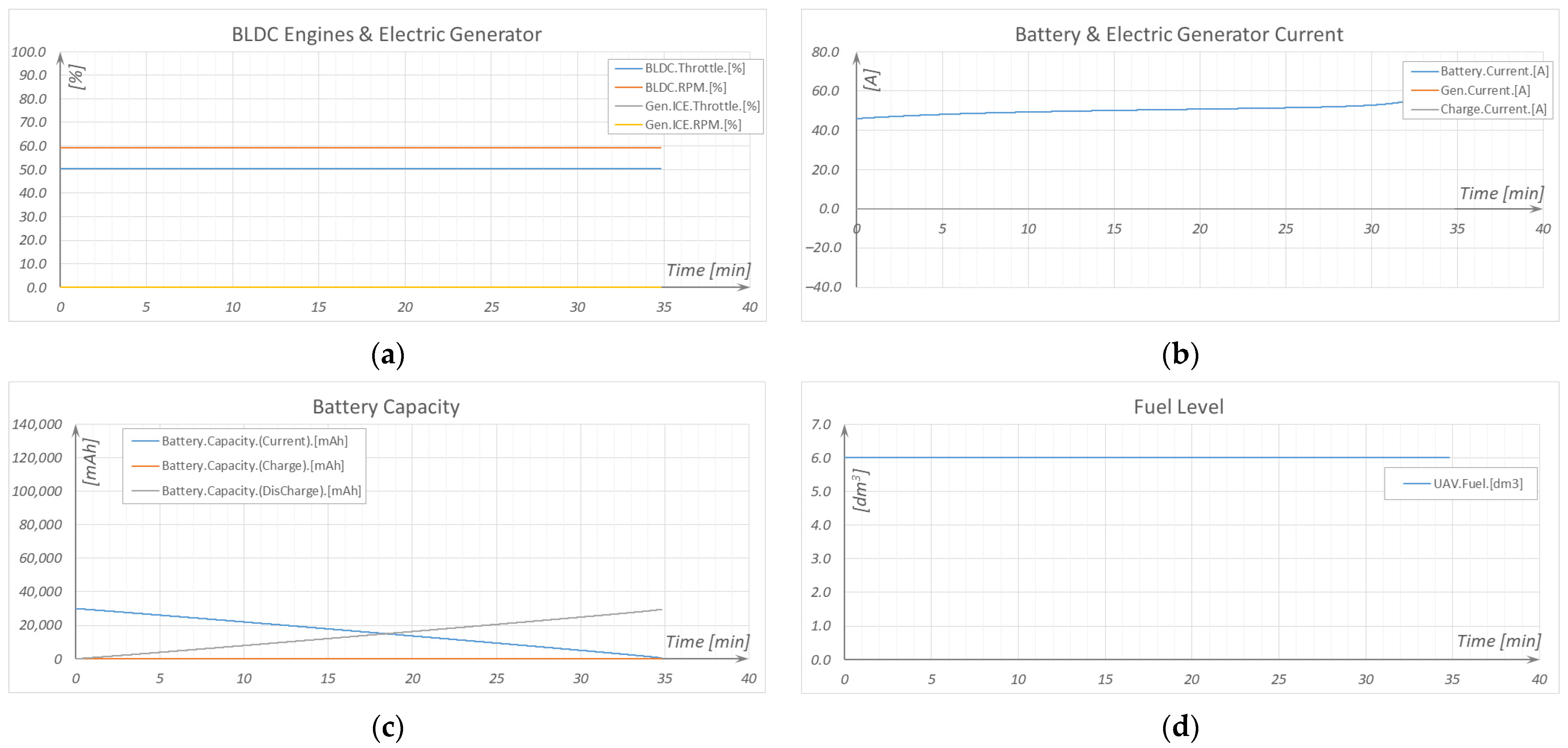
The BEV mode of operation (
Figure 7) is typical for current hobby modeling, commercial industry, and military solutions. In flight, all BLDC motors responsible for the MR UAV’s hover have the same throttle setting and constant propeller RPM (
Figure 7a). The current is drawn from the main battery alone (
Figure 7b), and the battery-low alarm is raised when low voltage is measured, allowing the UAV to return to land safely.
Figure 7c presents the current main battery capacity and capacity used to power the BLDC motors.
Figure 7d shows a constant volume of fuel because the HEPS is not employed in operation.
In the case of HEV mode of operation, two cases were considered during the simulations (
Figure 8 and
Figure 9), differing in specific fuel consumption values.
During hover, with HEPS having a more efficient ICE Generator (lower SFC), three stages of main battery charging can be seen. Fuel consumed (
Figure 8d) during each ICE Generator operation stage reduces the UAV’s weight, which further leads to lower electrical power demand from the BLDC thrust motors (
Figure 8a). It is important to mention that each successive charging stage requires less generated power to sustain hover and charge the main battery (
Figure 8b).
Regarding HEPS with a less efficient ICE Generator (higher SFC), only one full stage of main battery charging can be identified (
Figure 9a). The second stage is aborted because the fuel reserve is reached (
Figure 9d), and the ICE Generator is shut down to prevent operation without fuel, which could reduce the HEPS’s service life.
Two HEV operation cases were simulated because accurate real-world fuel consumption data will only become available after bench testing the HEPS under load. It can also show how the ICE Generator efficiency influences the HEPS-powered UAV platform operation.
Taking the MTOW of the UAV along with the smaller main battery capacity will shorten the flight time in the BEV mode. In the HEV mode, it will cause more frequent ICE Generator operation (the main battery charging and discharging cycles).
5. Discussion and Conclusions
Unlike heavy chemical battery technologies commonly used in multi-rotor UAVs, alternative technological solutions have been developed to reduce greenhouse gas (GHG) emissions.
Hydrogen fuel cells can provide electrical energy for several hours of flight, and refueling is significantly faster than battery recharging [
3,
47]. However, fuel cells can reach a level of efficiency as high as 60%, which is lower than lithium batteries (over 90%). They also require auxiliary onboard equipment, which results in an efficiency drop and increased system complexity. Given hydrogen’s density of just 0.089 kg/m
3 at standard temperature and pressure, it is very important to ensure safe storage of pure hydrogen under extremely high pressures and low temperatures in onboard tanks.
Battery replacement, in the form of supercapacitors, has recently been focused on as energy storage [
3]. In comparison to batteries, they have much higher power but much lower energy density and are able to operate in a large temperature range with overcharge tolerance and low maintenance costs. Although they can help reduce voltage fluctuations on the onboard power bus, they are best employed as an additional power source in a UAV hybrid power system.
The replacement for aviation fossil fuels has recently been seen in biofuels, also known as Sustainable Aviation Fuel (SAF) [
48], which can be produced from any bio-renewable carbon raw material. As the most common source for the biofuel manufacturing process is plants that absorb CO
2 during growth, the combustion releases roughly the same amount of CO
2, which makes the entire life cycle carbon neutral. Of course, some additional emissions may occur during the manufacturing and transportation processes, but overall, CO
2 emissions from biofuel combustion are still expected to be reduced by 80% compared with fossil fuels. Furthermore, biofuels contain fewer impurities (such as sulfur), so sulfur dioxide and soot emissions may be reduced.
Along with hardware solutions come software technologies that govern the fuel combustion and charge/discharge processes more efficiently. While the hybrid electric drive charge/discharge controllers’ rules of operation are not easily found (this is the main aim of this research), there is much well-documented research concerning the use of machine learning (ML)- and artificial intelligence (AI)-based algorithms in photovoltaic (PV) systems, which are based on increasing the efficiency of Maximum Power Point Tracking (MPPT) [
49,
50,
51]. Given that during Li-Poly battery cell charge/discharge, the main focus is placed on controlling the voltage and keeping the cell current in a safe range, those solutions present a possible translation to aviation hybrid drives.
Hybrid electric drives for UAVs in logistics, surveillance, search, and rescue operations are often considered a more environmentally friendly alternative to traditional gasoline-powered vehicles. They present both advantages and challenges from an ecological point of view. The environmental impact is imposed by manufacturing processes, energy sources, operational benefits, and lifecycle management. With reasonable fuel consumption and greenhouse gas emissions, hybrid electric vehicles are an acceptable solution in opposition to existing heavy chemical battery technology.
The conducted market analysis allowed for the selection of the hybrid electric propulsion system prototype components for a multi-rotor unmanned aerial vehicle with a maximum take-off weight of 25 kg. The developed and built digital twin was based on the technical data and operating parameters available in source materials provided by the manufacturers.
Based on the obtained digital twin simulation results, it is proven that the use of a hybrid electric drive allows for a significant increase in the flight time of a multi-rotor unmanned aerial vehicle and that an endurance of no less than 2 h of flight time should be met after a full integration of the hybrid electric propulsion system. At the same time, the developed DT can be used as a tool for optimizing the operation of the HEPS prototype and for redefining mathematical models of individual components based on data from the bench tests. If the requirements are changed or the main components are modified (manufacturer modification or end of production), it is very easy to update the DT and conduct needed simulations to define the expected way of operation.
Therefore, a properly tuned digital twin and built SAF-powered HEPS prototype would enable a soft transition from fossil fuels, allowing energy generation with higher efficiency and lower GHG emissions.


