1. Introduction
With the rapid advancement of mobile Internet and IoT technologies, traditional centralized cloud computing architectures have struggled to meet the low-latency demands for real-time services, often causing core network congestion and privacy vulnerabilities [
1]. This challenge has catalyzed the emergence of cloud–edge collaborative computing architectures that synergize cloud-scale data processing with edge nodes’ localized responsiveness, thus forming a “cloud–edge–end” triad that optimizes resource utilization and service quality [
2,
3]. As illustrated in
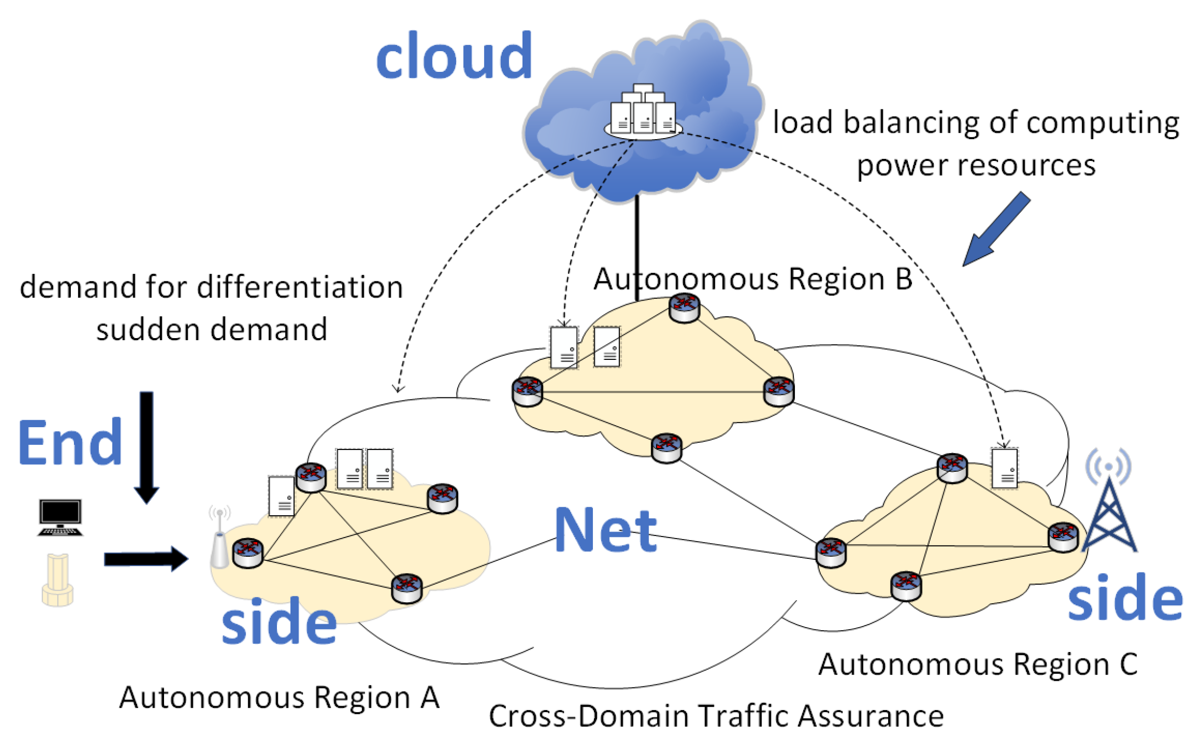
Figure 1, the Network Collaborative Open Control Architecture (NCOCA) epitomizes this paradigm through distributed autonomous decision-making and entity-level coordination, which contrasts sharply with legacy centralized systems prone to single-point failures and scalability constraints [
4]. By decentralizing management functions to network entities, NCOCA enhances operational efficiency while enabling mission-critical applications such as millisecond-response power grid inspections and the distributed vehicular network processing of dynamic road conditions [
5].
However, existing architectures still face serious challenges in coordinating heterogeneous device capabilities and meeting real-time mission requirements. Heterogeneous devices, varying widely in computational, storage, and network capabilities (e.g., grid sensors, IoT terminals, industrial park energy devices, fog computing nodes, and industrial IoT equipment), present significant challenges in resource integration, interoperability, and dynamic access stability. For example, it is necessary to resolve data transmission and task offloading strategies among cameras, edge controllers, and cloud servers due to the computational disparities among these devices [
6]. Ren et al. [
7] and Deng et al. [
8] highlight how the fragmented capabilities of IoT terminals, photovoltaic nodes, and energy storage devices give rise to cross-domain collaboration and dynamic resource scheduling issues. Liu et al. [
9] proposed an edge-cloud collaborative information interaction mechanism and distributed iterative optimization algorithm for industrial park integrated energy systems, which can effectively improve multi-energy synergy efficiency. In smart factories and energy systems, fog computing nodes and industrial sensors face reliability challenges during dynamic access owing to the complexities of heterogeneous resource management [
10,
11]. Dynamic tasks further complicate this landscape with strict real-time requirements—the use of real-time traffic processing in telematics, UAV target tracking, and analogous tasks demand millisecond-level responses to handle load fluctuations and tight time windows—thereby avoiding decision-making errors [
7,
8,
12]. Smart logistics scenarios experience amplified scheduling complexity stemming from environmental uncertainties such as abrupt path changes or equipment failures [
13,
14]. Additionally, grid video surveillance and fog computing tasks are constrained by the need for latency-sensitive real-time data processing [
10,
15]. The main contributions of this paper to address the “fragmented” capabilities of heterogeneous devices and the “real-time” requirements of dynamic tasks are as follows:
- (1)
Delay-driven dynamic scheduling mechanism: the real-time monitoring of network status (channel quality, node load), the dynamic adjustment of task allocation strategy, and the resolution of resource competition conflicts;
- (2)
Decentralized collaborative decision-making framework: design distributed algorithms that allow edge nodes to autonomously optimize local queues, avoiding the single-point failure inherent in centralized architectures;
- (3)
Lightweight 2D matching mechanism: Optimize resource allocation for high-priority tasks by incorporating latency and queue backlog perception and downgrading 3D resource matching to a 2D problem. Through comparisons with traditional algorithms (PDPRA, CSA, simple neural networks) in NS-3 simulations, the proposed approach demonstrates excellent adaptability and robustness in large-scale dynamic network environments.
The rest of this paper is as follows:
Section 2 provides a comprehensive overview of related works.
Section 3 elaborates on the distributed cloud–edge collaborative control modeling with consideration of network transmission delay.
Section 4 introduces the cloud–edge collaborative data processing optimization algorithm based on processing delay and backlog perception matching. In
Section 5, the effectiveness of the proposed distributed cloud–edge collaborative scheduling algorithm (with network transmission delay constraints) is validated through simulation experiments and compared against three other algorithms.
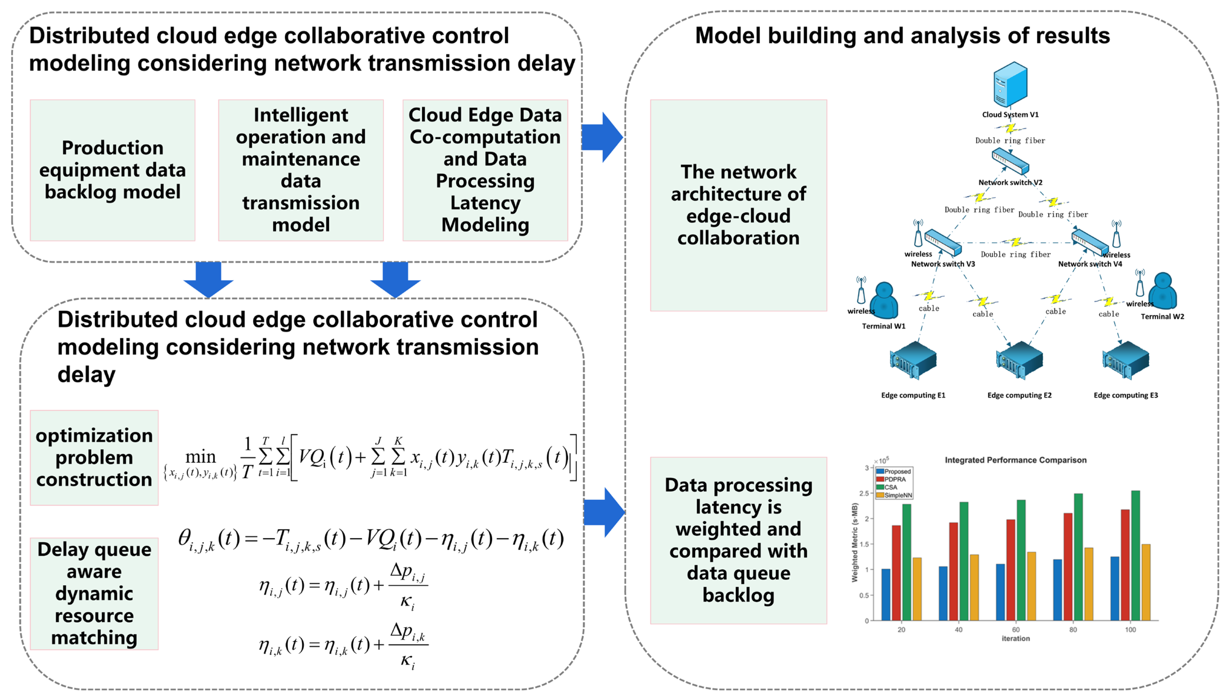
Section 6 concludes the entire work. The overall research content framework is shown in
Figure 2.
2. Related Work
The development of cloud–edge collaborative architectures aims to optimize latency and energy consumption through distributed resource management, while existing research focuses on task offloading strategies, resource allocation optimization, and algorithm design to balance multiple objectives such as latency, energy consumption, and quality of service (QoS).
Earlier studies assumed task independence or only considered simple dependencies, a limitation that makes models insufficient for complex workflows. Karimi et al. [
16] proposed a deep reinforcement learning (DRL)-based task offloading framework to jointly optimize the resource allocation between edge and cloud nodes, thereby reducing response time and improving task acceptance rates. However, this framework fails to account for the impact of network bandwidth fluctuations. Li et al. [
17] designed an edge–cloud cooperative algorithm based on Lyapunov stability theory to balance queue delay and energy consumption, but it overlooked inter-task dependencies, leading to limited scheduling efficiency for complex workflows.
To address the task dependency problem, Tang et al. [
18] introduced a directed acyclic graph (DAG) to describe task dependency and proposed a deep reinforcement learning algorithm based on task prioritization (TPDRTO), improving the scheduling efficiency of the dependent tasks. Notably, its high deep neural network training complexity in large-scale scenarios and real-time performance are insufficient. Wang et al. [
19] combined blockchain technology and incentive mechanism to facilitate edge node collaboration via smart contracts, but this approach increased system communication overhead, potentially degrading overall performance. Chen et al. [
20] proposed the concept of computational task contouring for complex workflows in the medical and industrial domains, designed a DRL task scheduling algorithm to optimize resource usage and computational cost, and verified that it outperformed the baseline approach through NS-3 simulation. However, the algorithm did not address the coupling effect of bandwidth allocation. Collectively, these studies highlight that modeling task dependencies and achieving efficient scheduling remain outstanding challenges.
Heuristic and meta-heuristic algorithms are widely used in energy and performance optimization. Hussain et al. [
21,
22] proposed Energy and Performance Efficient Task Scheduling Algorithms (EPETS), which dynamically adjust resource allocation to reduce the overuse of high-speed resources via task slack time. However, this approach is only applicable to standalone tasks. The multi-quantum-inspired genetic algorithm (MQGA) proposed by the authors’ team addresses medical workflow scheduling to optimize Makespan and energy consumption, but it suffers from limitations imposed by quantum computing hardware environments and lacks universal applicability.
Data-driven heuristics are gradually becoming mainstream. Bao et al. [
23] proposed a gated recurrent unit (GRU)-based edge–cloud cooperative prediction model (TP-ECC), which dynamically adjusts resource allocation by integrating traffic prediction to enhance system foresight, but it is confined to single-edge-node scenarios. Liu et al. [
24] combined CNN, LSTM, and attention mechanism to achieve efficient decision-making in dynamic environments with 30–50% computational efficiency improvements, but this approach relied on large amounts of labeled data and exhibited limited generalization ability. The MoDEMS system used the sequential greedy algorithm to generate migration plans, applying a Markovian mobility prediction model to reduce the user latency, but it overlooked global suboptimality arising from resource competition among multiple users [
25]. To address the Pareto-optimality challenge in multi-objective optimization, Pang et al. [
26] proposed a dynamic weight adjustment algorithm, which balances latency and energy consumption optimization objectives in real time via reinforcement learning and mitigates the insufficient adaptability of traditional static weight allocation strategies in dynamic telematics environments. However, it fails to account for the compatibility issues of heterogeneous devices.
Exact optimization methods based on mathematical planning, such as Integer Linear Programming (ILP) or Mixed-Integer Programming (MIP), theoretically approximate the optimal solution, but the computational complexity grows exponentially with the task size. The DEWS algorithm produced by Hussain et al. [
27] constructs an optimization model, which is solved by the Variable Neighborhood Descent (VND) algorithm, to minimize the energy cost under deadline constraints, yet its time complexity
renders it ill-suited for large-scale real-time scenarios. The subsequent EPEE algorithm integrates electricity price fluctuation and data transmission time to achieve energy efficiency and cost co-optimization, but it still assumes static data center resource allocation and neglects real-time load variations [
28].
The time-varying nature of edge node resources and network bandwidth in dynamic environments thus causes traditional static scheduling strategies to fail. Although algorithms such as DRL try to handle dynamic states, real-time performance and convergence in large-scale scenarios still need to be optimized. For example, CTOCLA introduces an attention mechanism to handle task weights, but fails to model the additional delay induced by cross-domain data transmission security and privacy protection [
24]. MoDEMS exhibits limited dynamic adaptability, as abrupt changes in user mobility patterns increase migration plan failure probability by approximately 20% [
25]. To tackle dynamic resource fluctuations, Jiang et al. [
29] proposed a deep reinforcement learning (DRL)-based cloud–edge cooperative multilevel dynamic reconfiguration method for the real-time optimization of urban distribution networks (UDNs). The method is divided into three levels (feeder, transformer, and substation), combining a multi-intelligent system (MAS) with a cloud–edge architecture, and adopting a “centralized training-decentralized execution” (CTDE) model. Meanwhile, Li et al. [
30] proposed a cloud–edge cooperative approach based on MADDPG for the integrated electric–gas system (IEGS) scheduling problem. The electricity and gas systems are computed independently at the edge, and the cloud optimizes globally based on the boundary information. However, it overlooks the parallelism limitation stemming from the cloud’s reliance on edge parameter transfers.
There are three systemic deficiencies. Firstly, there is a lack of dynamic delay modeling, ignoring the impact of network fluctuations and interference on task offloading. This results in delay estimation bias. Secondly, there is insufficient decentralized scheduling, and the centralized architecture suffers from lagging state synchronization and privacy risks. Thirdly, there is an imbalance in multi-objective optimization, lacking a joint optimization framework for multiple objectives such as latency and energy consumption, making it difficult to meet the demands of complex scenarios. This paper systematically addresses these gaps through dynamic latency modeling, distributed collaborative decision-making, and lightweight resource matching:
- (1)
Dynamic adaptability: avoiding static model bias by the real-time sensing of network state.
- (2)
Privacy and reliability: decentralized architecture circumvents a single point of failure.
- (3)
Multi-objective synergy: balancing delay, energy consumption, and resource fragmentation through a two-dimensional matching mechanism.
3. Distributed Cloud–Edge Collaborative Control Modeling Considering Network Transmission Delay
A distributed cloud–edge collaborative data processing architecture is a system that combines computational power from both cloud and edge devices while accounting for network transmission latency. This architecture optimizes data processing to improve efficiency, reduce latency, and alleviate reliance on network bandwidth. Data generated or collected at edge devices can be transmitted to either the cloud or other edge nodes for processing. To mitigate the impact of transmission latency on performance, designers employ strategies such as edge-side preprocessing and adaptive task partitioning.
To address the dynamic interaction between network transmission and task processing, this section introduces a distributed cloud–edge collaborative control model. We first model the data backlog dynamics at terminals (
Section 3.1), subsequently presenting a transmission model that integrates channel characteristics and resource allocation (
Section 3.2). Finally, we systematically derive a comprehensive latency model (
Section 3.3) that combines computational delays at servers with network transmission delays across the cloud–edge continuum, serving as the foundation for the optimization algorithm in
Section 4. The nomenclature used throughout the paper is systematically presented and explained in
Table 1.
3.1. Production Equipment Data Backlog Model
Assume that there is I data acquisition terminal, represented by
. T data processing iterations are considered, expressed as
. In each iteration, according to the available communication and computing resources, the terminal will offload the locally cached data to the edge layer or cloud layer for collaborative data processing. The locally cached data of the terminal can be simulated using the cache queue, and the queue backlog updates can be represented by the following formula:
where
and
are the amounts of data collected and transmitted in the t iteration, representing the input and output of the queue, respectively.
Equation (1) describes the dynamic balance of terminal cache: the current backlog equals the previous backlog plus new data minus transmitted data. This captures the accumulation of data that requires offloading, directly influencing subsequent transmission and processing decisions.
3.2. Intelligent Operation and Maintenance Data Transmission Model
Assume that there are a total of K servers that form the set
, where
represents the cloud server and
represents the edge server. Considering the end–edge channel, the end–cloud channel, and the cloud–edge load profile, the available communication and computation resources are partitioned into J resource blocks, denoted as
. In the
tth iteration, the signal-to-noise ratio of the terminal
transmitting the captured data to the server
through the resource block
is expressed as follows:
We define the matching indicator variable between the terminal and the resource block as
.
shows that the terminal
matches with the resource block
at the
tth iteration; otherwise,
. We define the matching indicator variable between the terminal and the server as
.
shows that the terminal
offloads the data to the server
at the
tth iteration; otherwise,
. Based on Equation (2),
the transmission rate for the transfer of data to the server
from the terminal
is calculated as follows:
The amount of data
transmitted in the
tth iteration is expressed as follows:
where
denotes the iterative transmission length.
The data transmission delay for transferring data from
to
is expressed as follows:
Consider T data processing iterations, denoted as . In each iteration, the terminal offloads the locally cached collection data to the edge layer or the cloud layer for collaborative data processing, depending on the available communication and computation resources. The locally cached data is modeled by the cache queue shown in Equation (1).
Equations (2)–(5) link channel quality (SNR) to transmission efficiency: higher SNR (better channel) enables higher rates and lower delays. This forms the basis of resource block allocation, as terminals prefer resource blocks with higher to minimize transmission latency.
3.3. Cloud–Edge Data Co-Computation and Data Processing Latency Modeling
The edge server or cloud server can process the data from the endpoints only after it has processed its own computational load. The latency to process the collected data from
is expressed as follows:
where
is the
delay when waiting to complete its computational load,
is the computational resources required to process the unit
data, i.e., computational complexity, and
is the computational resources provided by the resource block
.
The total latency incurred during task offloading consists of two main components. The first part is the CPU cycle consumed by the execution of the task on the server and this is termed execution latency. The other part is the time taken by the task to transfer between different servers during the offloading process. The execution latency further comprises the task execution latency on the server can be subdivided into the processing latency of the task and the queuing latency waiting for the previous task to finish processing. The task processing latency is usually related to the server performance and the computational resources required by the task. Let the total offloading latency of the system be T, where the execution latency is
, the queuing latency is
, the processing latency is
, the offloading latency for transmitting the task to other servers is
, and the transmission latency for the task to be transmitted from one edge server to another edge server is
. The execution delay
of task
is expressed in Equation (7).
Let K be the set of offloaded yet incomplete tasks on the ECS; the queuing latency
of
is shown in Equation (8).
The offload latency of a task can be decomposed into six parts, including the offload latency, the transmission latency between edge servers, the offload latency from the edge servers to the macro base station, the offload latency from the edge servers to the central cloud server, and the offload latency from the macro base station to the central cloud server. The offload delay of the task transmission to another server depends on the size of the task and the transmission power of the terminal. The offload delay of the task can be formulated using Equation (9).
The binary variable
indicates whether the transmission uses the cross-edge server mode, and
indicates that the transmission is performed in cross-edge server mode.
, the transmission delay
between edge servers, is determined using Equation (10).
When a task cannot be offloaded on the local terminal, the cloud server will assign a more reasonable transmission mode to the task—that is, the wireless transmission mode—and set the transmission delay to
, as shown in Equation (11).
indicates the task transmission mode selected by the cloud server, represents the task transmission times, and indicates the task transmission rate of the terminal.
Due to the limited storage and computing resources of the edge server, when the edge server cannot handle task offloading, it will offload the task to the central cloud server. However, due to the long distance between the edge server and the central cloud server, frequent tasks will generate large energy consumption, which reduces the utilization rate of system resources. In this architecture, macro base stations with large computing resources and storage resources are placed reasonably near to edge server farms to greatly reduce the probability of requests to the central cloud server, thereby reducing delay and system energy consumption and effectively improving resource utilization. Then, the transmission delay of
from the edge server to the macro base station is
, as shown in Equation (12).
where
and
are the amounts of data collected and transmitted in the t iteration, representing the input and output of the queue, respectively.
We set the transmission delay of
offloaded data to the central cloud server through the macro base station
, as shown in Equation (14).
The tasks generated by the terminal can be executed on four types of servers: terminal-local, edge server, macro-base station, and central cloud server. The total offloading delay of
is
, as shown in Equation (15).
The total offloading delay of the system is shown in Equation (16).
5. Example Analysis
To verify the effectiveness of the proposed cloud–edge collaborative network architecture, the distributed cloud–edge collaborative control model, and the optimization algorithm based on processing delay and backlog perception, this section conducts experiments on the NS-3 simulation platform. The experimental objectives include verifying the adaptability of the network architecture, evaluating the effectiveness of the model and algorithm, and comparing its performance with the result of traditional methods. The experimental environment is configured with the NS-3 simulation platform (version 3.36), with hardware specifications of an Intel Core i5-4460 CPU, 3.8 GiB of memory, and a 64-bit Ubuntu 18.04.6 LTS operating system (running in a VMware virtualization environment with a 63.1 GB disk). The network topology is designed based on actual industrial operation and maintenance scenarios.
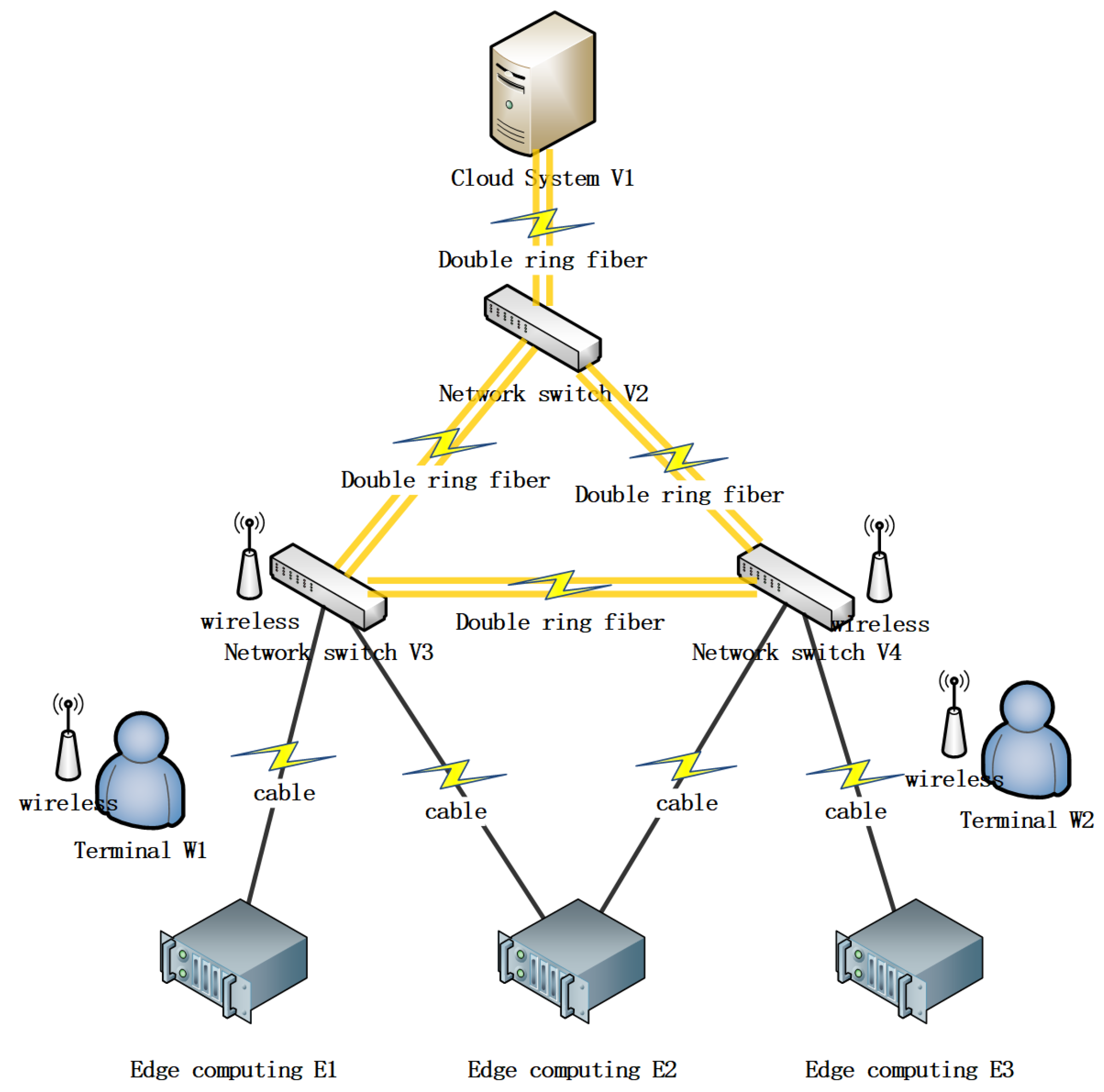
This paper builds a comprehensive network model, which includes a cloud system as the core hub. This is connected with three network switches, which are connected to build a high-availability internal network infrastructure. The model also includes three edge nodes, which are distributed in different geographical locations to provide services and data processing closer to users. In addition, two wireless nodes are integrated into the network to support the connection of mobile devices and sensors. The network architecture of edge–cloud collaboration is shown in
Figure 4.
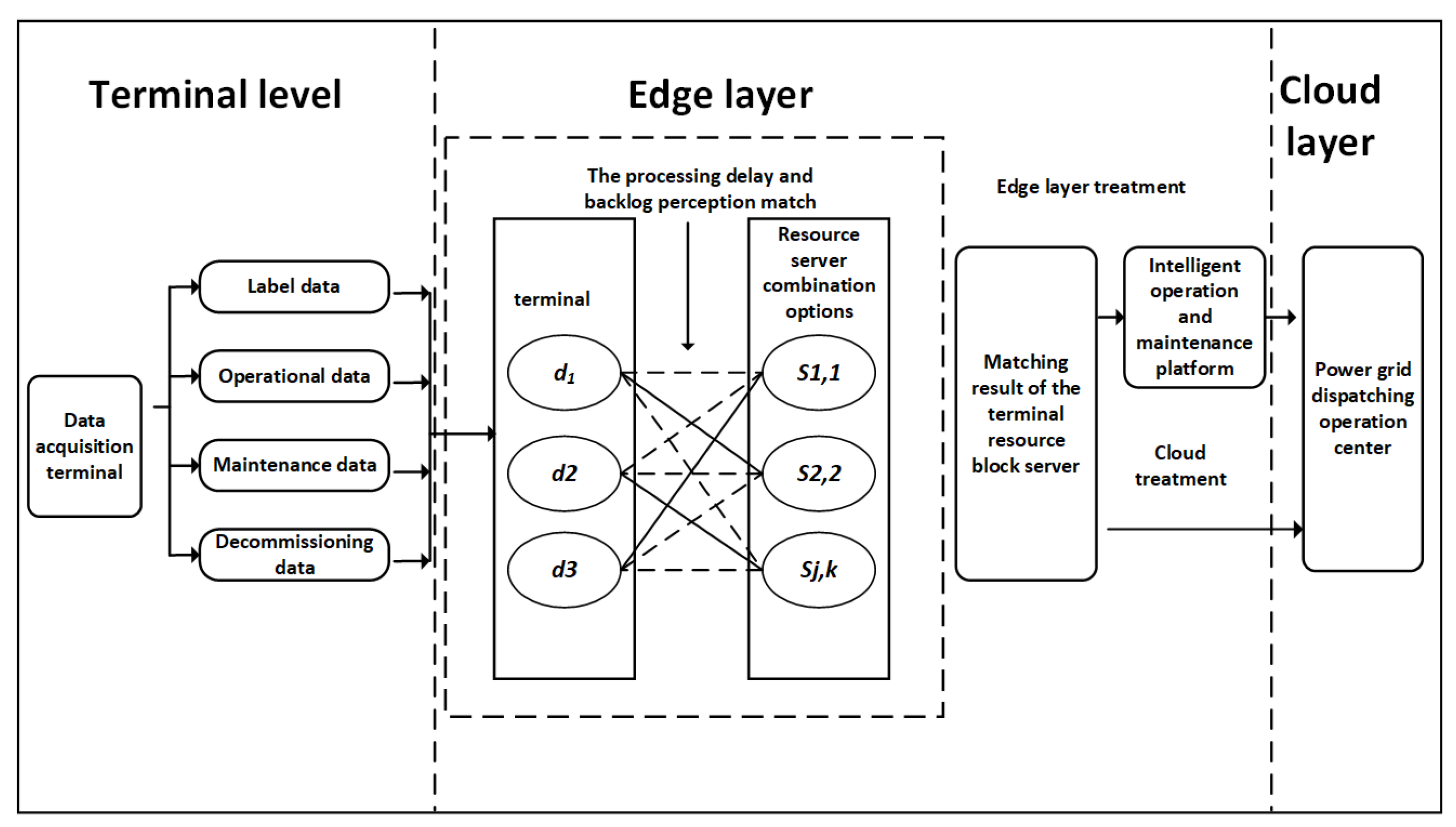
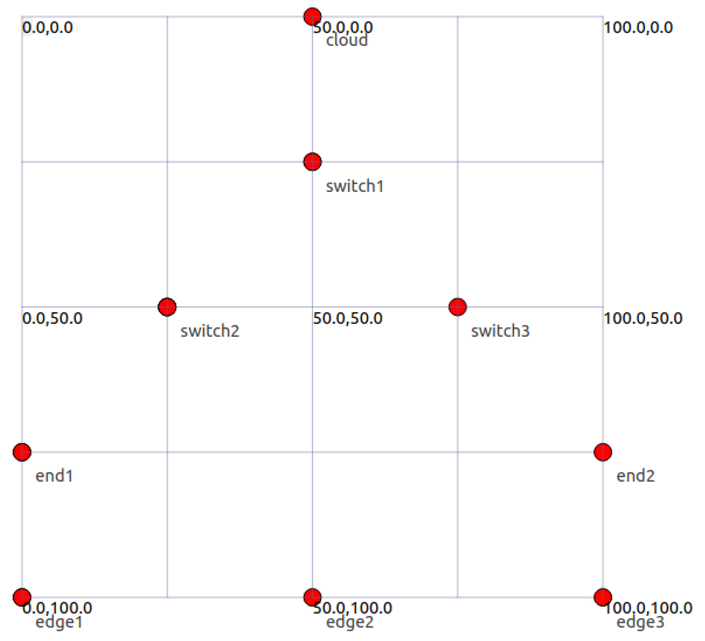
Based on the intelligent operation and maintenance scenario of a company’s actual production equipment, this paper considers various data acquisition terminals such as label data, operation data, maintenance data, and decommissioning data; the simulation is conducted using NS-3. Two simulation scenarios are as follows:
- (1)
In scenario 1, data is sent from the sensor at end 1 → switch 2 → edge device 1→ switch 2 → switch 1 → cloud-side complex operation → output results to switch 1 0→ switch 2 → edge device 1 → switch 2 → return to the actuator at end 1.
- (2)
In, scenario 2 data is sent from the sensor at end 1→ switch 2→ edge device 1→ switch 2 → switch 3 → switch 1 → cloud-side complex operation → output the result to switch 1 → switch 3 → switch 2 → edge device 1 → switch 2 → return to the actuator at end 1.
Use NetAnim to visualize the architecture model built in ns-3, as shown in
Figure 5.
The initial IP addresses of each point are shown in
Table 2.
5.1. Simulation Parameter
The initial values of the parameters and the initial coordinate settings for each node are shown in
Table 3 and
Table 4.
5.2. Contrast Algorithm Setting
In this paper, the performance of the proposed algorithm is verified, and three different cloud–edge collaborative data processing algorithms are used for comparison. The first algorithm is based on processing-delay-first resource block allocation (PDPRA), which is characterized by the transfer of all data to edge servers for processing. The second algorithm is the computing-resource-based algorithm (CSA), in which the terminal prefers the computing resources of the server but does not consider the quality of the channel or the backlog of the terminal data queue. The third algorithm, simple neural network-based resource allocation (Simple NN), employs real-time channel status and node load to generate resource allocation strategies. Although Simple NN offers basic online reasoning, it lacks dynamic adaptability and integration. Moreover, none of these three comparison algorithms can solve the problem of resource competition.
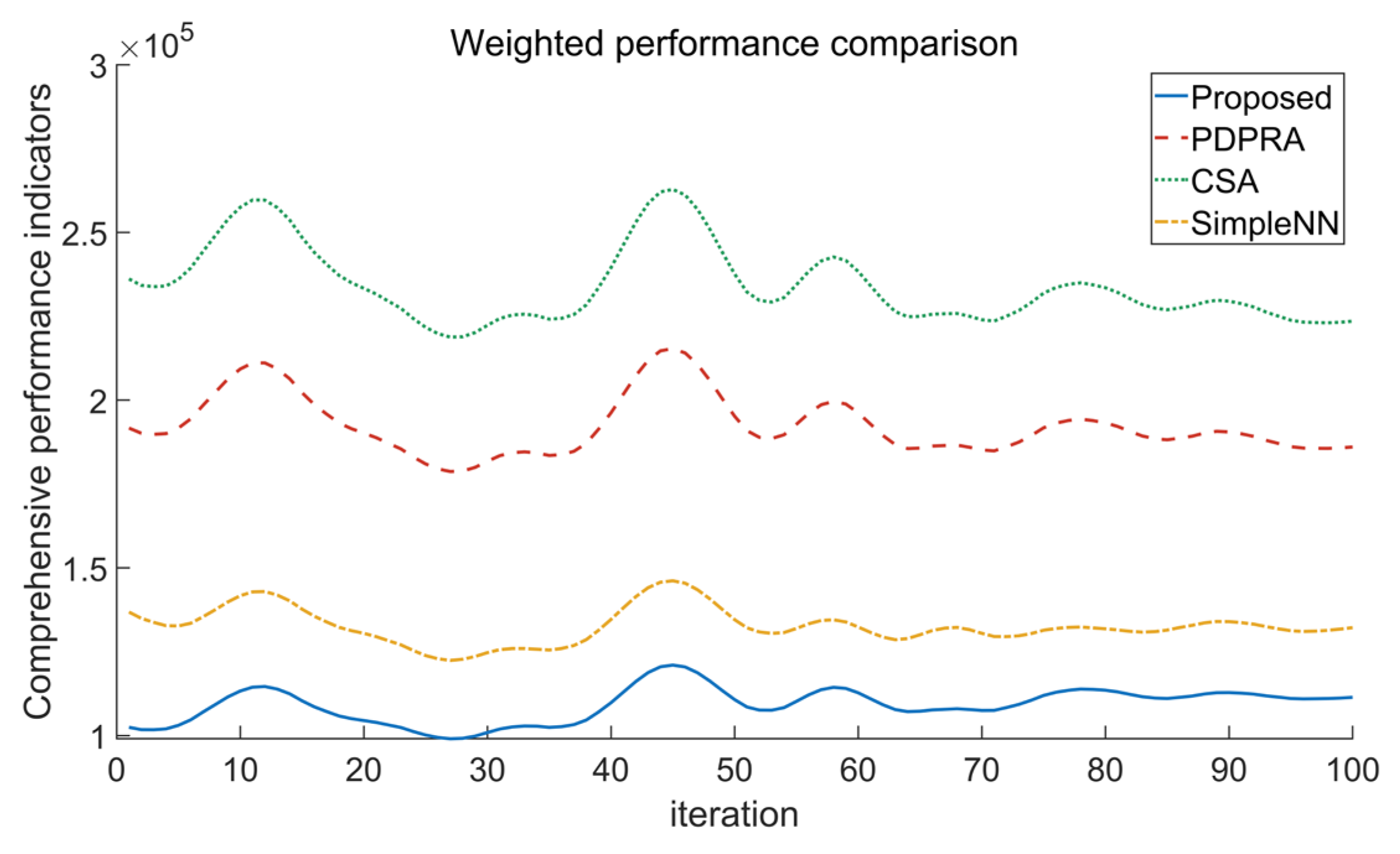
As illustrated in
Figure 6, the proposed algorithm demonstrates superior performance over PDPRA, CSA, and Simple NN, with its task execution time curve consistently occupying the lowest region. The algorithm achieves an average execution time reduction of 28–35% compared to the benchmark methods. This can be mainly attributed to its multi-objective dynamic optimization framework, which integrates real-time channel quality monitoring, node load balancing, and queue backlog awareness. Through a conflict-aware weighted resource-matching strategy, the algorithm dynamically optimizes the trade-off between transmission and computation during iterative updates.
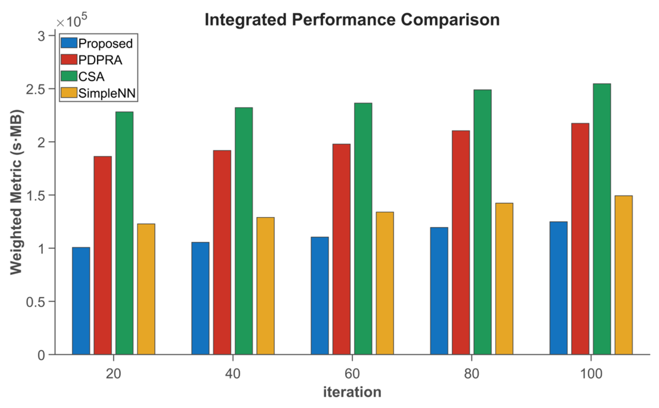
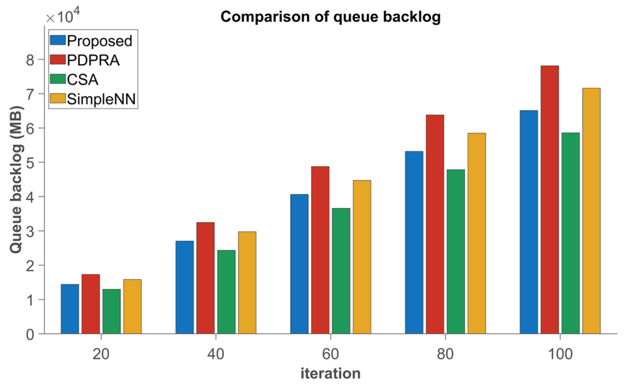
The performance comparison in
Figure 7 shows that the proposed algorithm reduces data processing latency by 11.05%, 12.18%, and 18.4%; decreases data queue backlog by 13.35%, 15.2%, and 22.7%; and outperforms PDPRA, CSA, and Simple NN, respectively. These improvements can be attributed to the new algorithm’s consideration of the differences in processing delay caused by resource blocks and the differences in terminal data queue backlog caused by server selection, which are weighted according to different choices. In addition, the new algorithm can better solve the matching conflict, and updating the matching cost ensures a smaller delay and data queue backlog for high-priority terminals. In contrast, the PDPRA algorithm only optimizes processing latency while ignoring server resource competition and matching conflicts, resulting in suboptimal performance. The CSA algorithm neglects communication resource contention, whereas the Simple NN algorithm, constrained by its static neural network architecture, exhibits increased latency and worsened queue backlog in dynamic scenarios.
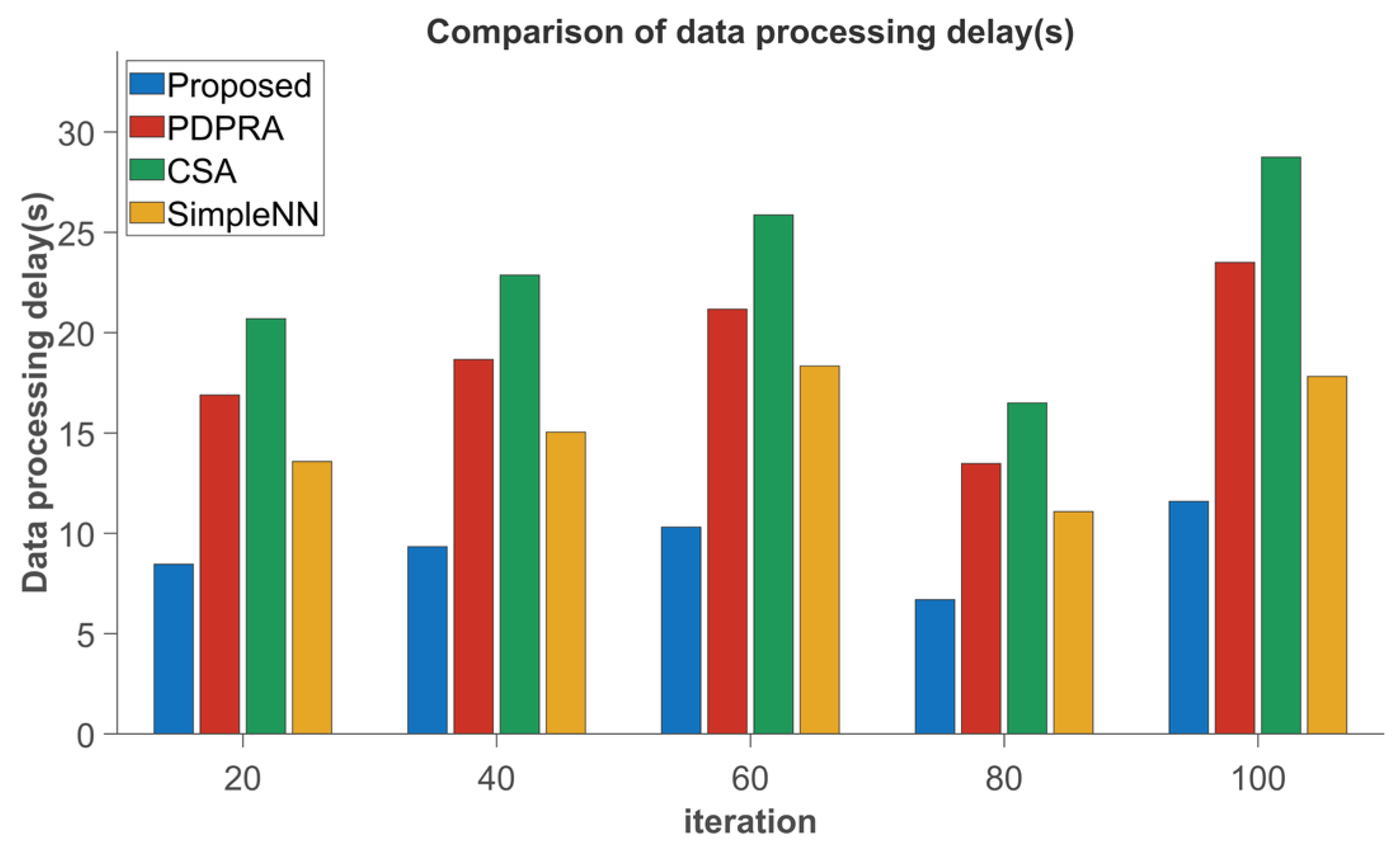
As demonstrated in
Figure 8 and
Figure 9, the proposed algorithm significantly outperforms PDPRA, CSA, and Simple NN, achieving 6.26%, 13.18%, and 19.2% reductions in data processing latency, and 13.57%, 16.16%, and 22.5% improvements in queue backlog mitigation, respectively. This improvement is due to the new algorithm’s integration of the communication and computing resources of the cloud and edge layers, which are organized into resource blocks and combined with cloud–edge servers through the Cartesian product. This approach allows terminals to better select servers and resource blocks and transfer data to edge or cloud servers for computation, significantly reducing data processing delays and data queue backlogs.
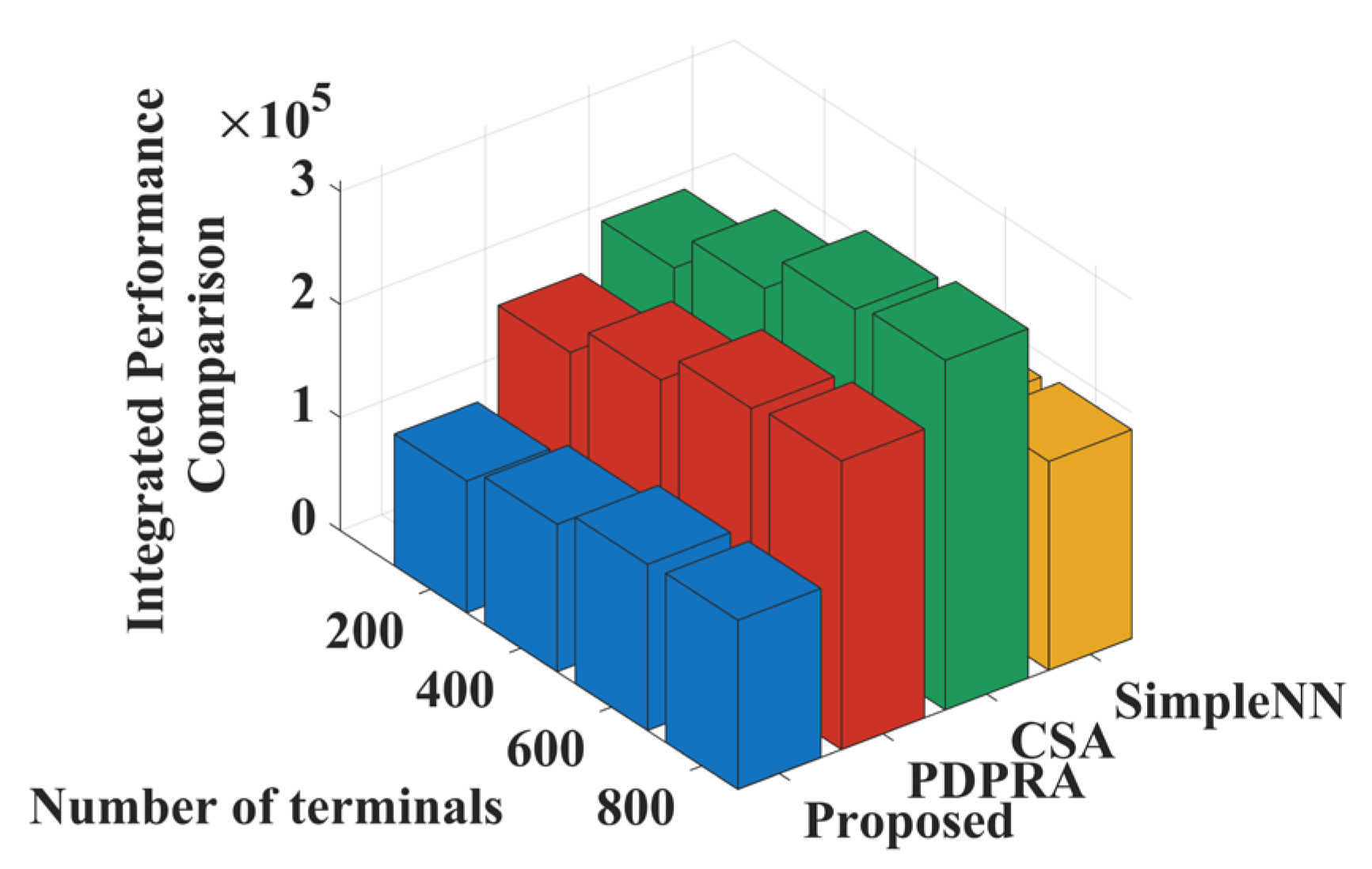
Figure 10 shows the weighted sum comparison of data processing delay and data queue backlog when the number of terminals increases in a large-scale device access scenario. As the number of terminals grows, the number of resource blocks that can be occupied by terminals decreases accordingly, resulting in an upward trend in the weighted sums of the three comparison algorithms, namely, PDPRA, CSA, and Simple NN. When the number of terminals exceeds 200, the number of terminals choosing the same server increases significantly, the processing capacity of communication and computation resource blocks decreases significantly, and the competition between terminals and servers for high-processing-capacity resource blocks intensifies, resulting in a steep increase in the weighted sum of the three comparison algorithms. In contrast, the proposed algorithm effectively mitigates the resource competition conflict by guiding terminals to preferentially match resource blocks with better processing capacity with server combinations through the matching cost iterative optimization mechanism in the case of declining resource processing capacity, and its weighting and growth are significantly smaller than those of the comparison algorithms.
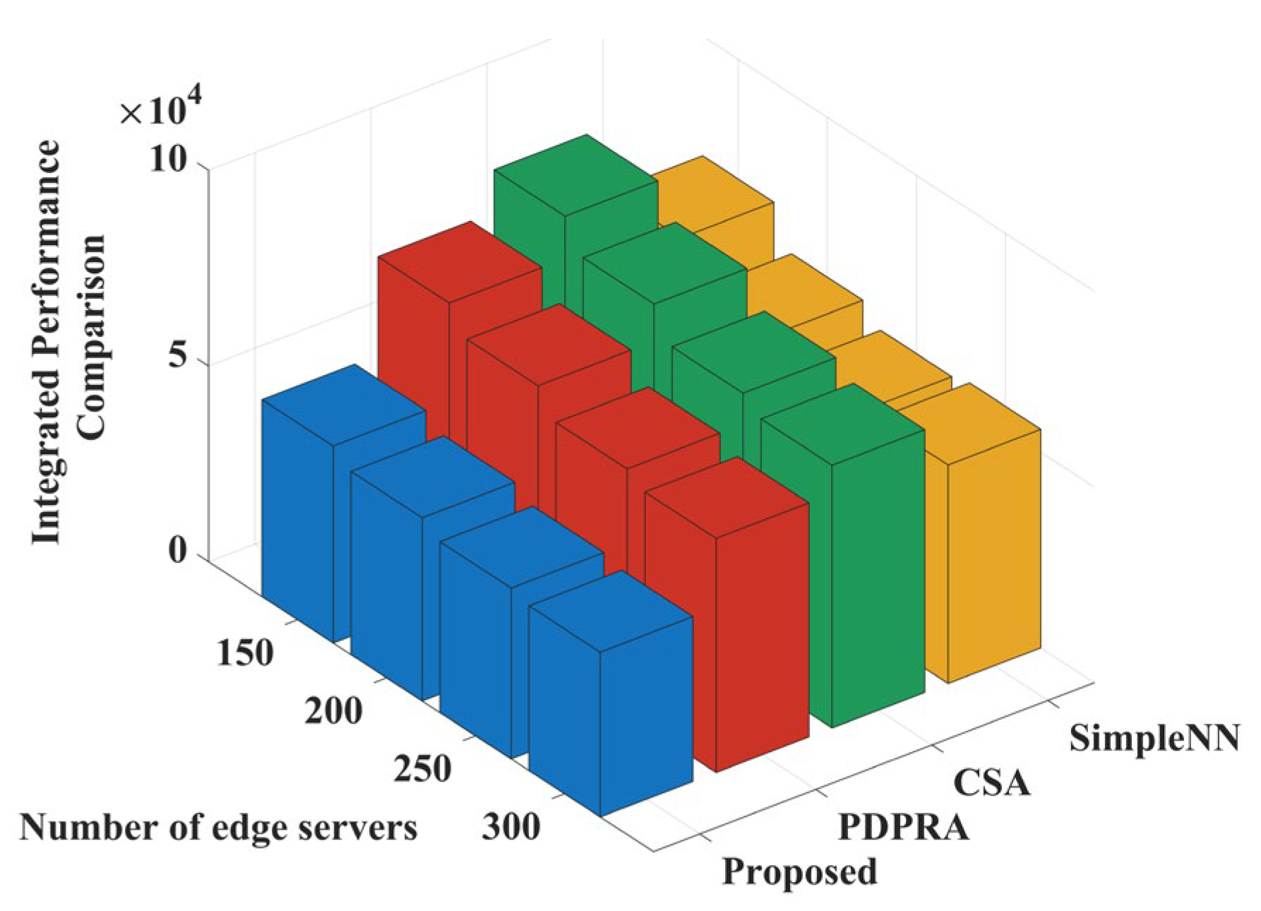
Figure 11 shows the weighted sum comparison of data processing delay and data queue backlog when the number of edge servers increases in the large-scale device access scenario. When the number of edge servers increases, the total number of high-performance servers in the system rises, and the overall processing capacity of the edge layer increases significantly. Since the PDPRA, CSA, and Simple NN algorithms also achieve some processing capacity increase when server resources are sufficient, the weighted sums of all three algorithms show a decreasing trend. The proposed algorithm further dynamically selects the optimal servers through a delay- and backlog-aware mechanism to reduce the queue backlog while lowering the data processing delay when there is a surplus of server resources. As a result, its weighted sum performance decreases in a more pronounced fashion and is consistently superior to the values of the comparison algorithms.
At the same time, if there is a data queue backlog at the terminal of the current iteration, according to Equation (1), the backlog data will be transferred to the edge or cloud server for processing in the next iteration. Through the rational selection of resource blocks and servers by the new algorithm, the data queue backlog is kept at a low level, and the system performance is further optimized.
5.3. Simulation Result
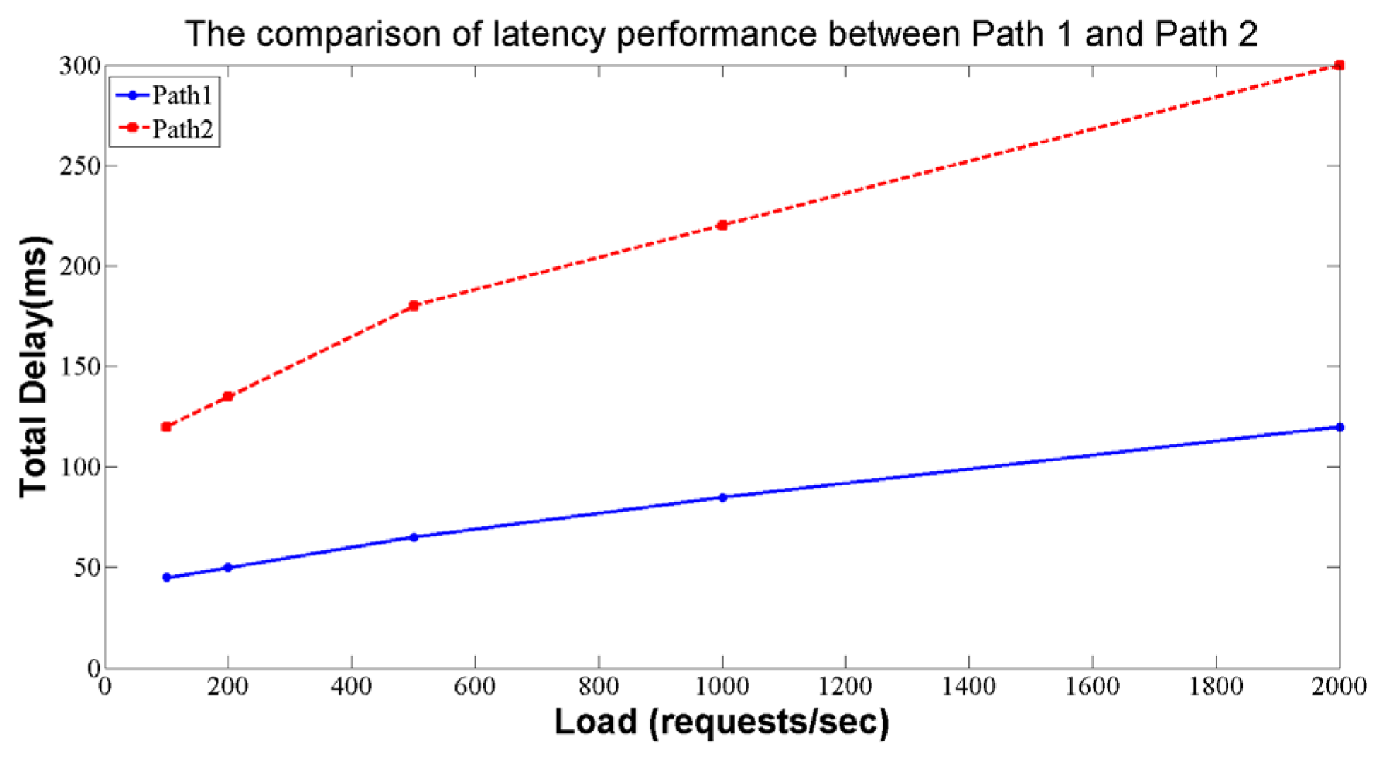
The comparison of latency performance between Path 1 and Path 2 is shown in
Figure 12.
The delay in Path 2 is significant due to the following reasons:
- (1)
Additional Path Switching: In Path 2, the data needs to pass through three distinct network switches. The presence of multiple-path switching results in a longer transmission path, thereby increasing overall latency.
- (2)
Increased Network Devices: Path 2 contains a relatively large number of network devices. Each time data is transferred from one switch to another, packets need to be processed and forwarded, which introduces delays in communication and coordination between different devices.
- (3)
Potential Congestion: The involvement of additional network devices and path switching in Path 2 heightens the potential risk of network congestion. This congestion can lead to packet queuing during transmission, which further exacerbates latency.
Taking these factors into account, the latency of Path 2 is relatively high due to the introduction of additional network switches and path switching, as well as more complex data transmission routes. High latency can adversely affect applications and real-time settings that require low latency. Therefore, designing a network architecture requires a careful balance between performance requirements and network topology to select the most appropriate transmission path.
The selection of transmission media directly influences the delay characteristics of the system, and the reasonable selection can balance performance and cost factors while satisfying application requirements, making it a crucial decision in network design and optimization.
As verified by simulation, the proposed delay-aware distributed cloud-edge scheduling framework exhibits significant performance improvements in dynamic network environments. As shown in
Figure 8 and
Figure 9, the algorithm outperforms the traditional approaches (PDPRA, CSA, Simple NN) by reducing the data processing latency by 6.26–19.2%, and improving the queue backlog alleviation rate by 13.57–22.5%. This superiority stems from its unique integration of the following components:
- (1)
Dynamic Network Modeling: Real-time monitoring of channel quality and node load, enabling adaptive task allocation and reducing transmission delays caused by outdated network state information.
- (2)
Distributed 2D Matching: By transforming 3D resource matching (endpoint-resource block–server) into a 2D problem, the algorithm efficiently resolves shared resource conflicts and reduces overall task execution time.
- (3)
Priority-Aware Resource Competition Solution: An iterative matching cost adjustment mechanism ensures that high-priority tasks are given priority for resource allocation, thus minimizing latency for latency-sensitive applications.
These results highlight the effectiveness of the framework in balancing computational requirements and network latency, addressing the central challenge facing traditional approaches that ignore dynamic transmission delays.
Although the proposed method shows good performance in simulation, its practical application still faces the following challenges. First, when an edge node fails suddenly (e.g., power interruption of industrial sensors or malfunctions in computation units), the existing architecture lacks real-time fault sensing and dynamic rescheduling mechanisms, and tasks relying on the node face the risk of timeout due to delayed migration to redundant nodes, potentially increasing task failure rates. Second, the movement of the equipment (such as AGVs, inspection drones) triggers channel fading, and the algorithm’s delay prediction model fails to track channel parameter changes in real time, potentially increasing task assignment error rates.
To further validate the algorithm’s universality in dynamic abnormal scenarios, the following experiments will be carried out in the future research. First, we will inject high-frequency random node failure events and sudden traffic congestion models into the NS-3 simulation environment, simulate extreme scenarios such as sensor node cluster failures in smart factories or sudden reductions in the bandwidth of industrial buses, and test the algorithm’s failure-aware delay and task rescheduling success rate. Second, we will develop a “mobile trajectory prediction” model to address the challenges of equipment mobility, and develop a “mobile trajectory prediction” model to address the challenges of equipment mobility. Further, to address the challenges of device mobility, we develop a joint mechanism of “mobile trajectory prediction and task pre-migration” to train LSTM prediction models with historical mobile data. The above experiments will systematically verify the robustness of the algorithm in dynamic disruption and mobile scenarios, and provide theoretical support for industrial-scale deployment.


