Article

Preparation of Lightweight and High-Strength Ceramsite from High-Silicon Lead-Zinc Tailings: A Sustainable Method for Waste Recycling

by
Ming Li
,
Chongjie Liao
,
Qi He
* and
Yifan Yang
School of Civil Engineering, University of South China, Hengyang 421001, China
*
Author to whom correspondence should be addressed.
Sustainability 2025, 17(10), 4523; https://doi.org/10.3390/su17104523
Submission received: 1 April 2025 / Revised: 7 May 2025 / Accepted: 13 May 2025 / Published: 15 May 2025

Abstract

:
This study proposes a sustainable method to convert high-silicon lead-zinc tailings (HS-LZT) into lightweight and high-strength ceramsite, aiming to address the issues of solid waste management and resource efficiency by using HS-LZT and kaolin as the main raw materials and silicon carbide (SiC) as the pore-forming agent. A sintering process was employed to prepare lightweight, high-strength ceramsite. X-ray diffraction (XRD), X-ray fluorescence (XRF), Thermogravimetric-differential scanning calorimetry (TG-DSC), and inductively coupled plasma optical emission spectrometer (ICP-OES) were used to analyze the physical composition and physical and chemical properties of the raw materials. The influence of raw material ratios, SiC content, sintering temperature, and sintering time on ceramsite properties was investigated, and the microstructure of the optimal finished ceramsite was analyzed. The results show that under optimal preparation conditions (70% [by mass percentage] of HS-LZT, 30% [by mass percentage] of kaolin, with an addition of 0.5% [by mass percentage] of SiC, a sintering temperature of 1200 °C, and a sintering time of 20 min), the LZT ceramsite achieved a compressive strength of 11.39 MPa, a bulk density of 724 kg/m3, and a 1 h water absorption rate of 4.82%. The leaching content of Pb and Zn of the sintered ceramsite samples is far less than the limit values of hazardous components in the leachate specified in the relevant standard. This study provides a potential pathway for the reduction, recycling, and environmentally sound utilization of HS-LZT, which is in line with the sustainable development concept of “treating waste with waste.”

1. Introduction

Lead-zinc tailings (LZT) are the residual solid wastes generated after the crushing and flotation of lead-zinc ores [1]. Lead and zinc mineral resources in China are widely distributed, and the production of lead and zinc ranks first in the world [2]. However, there are many lean ores and few rich ores, and the mineral composition is complex. Most of the lead-zinc ores are difficult to beneficiate [3,4]. Therefore, with the acceleration of mineral resource exploitation, the quantity of tailings has increased sharply [5]. According to the latest data from the Annual Report on China’s Comprehensive Utilization of Resources, the total amount of clearly measured LZT in China had reached 160 to 200 million tons by the end of 2021 [6], but the comprehensive utilization rate was less than 36% [7]. A large number of accumulated tailings have been generated due to their relatively low utilization rate [8]. These tailings are likely to cause disasters in nature, such as debris flows [9], and pollute the environment [10,11], occupy land resources [12], and affect development [13]. In recent years, the resource utilization of solid waste materials has made progress both in theory and in practice [14]. At present, the recycling technologies commonly used for LZT mainly focus on the production of engineering building materials such as cement, geopolymer, and building bricks [15,16,17,18]. There is limited research on the application of LZT in the field of ceramsite. Therefore, promoting the research and exploration of LZT on ceramsite is greatly significant for the comprehensive utilization of solid waste resources. Ceramsite is a kind of lightweight aggregate sintered from clay [19], shale [20], fly ash [21], and other solid wastes [22,23], which has the advantages of high compressive strength, low density, corrosion resistance, etc., and is widely used in construction and environmental protection [24,25]. With the growth of the demand for ceramsite, there is a shortage in supply of this natural resource and the environmental pressure is increasing, resulting in utilizing solid waste to produce ceramsite becoming an important direction. It can not only reduce costs but also contribute to the recycling of resources and green development.
Currently, there is less literature on the preparation of ceramsite using LZT as the main raw material. Moreover, all the existing studies utilize low-silicon LZT and adopt the sintering method to prepare high-strength ceramsite, so the utilization rate of LZT remains at a relatively low level. Luo et al. [26] prepared ceramsite using low-silicon LZT (with a SiO2 content of 3.52%) and coal gangue as raw materials. The results showed that when the content of LZT is less than 30 wt.%, LZT and gangue can be used for the preparation of ceramsite, and the prepared ceramsite is in line with the environmental safety requirements. However, as far as the physical properties of ceramsite are concerned, when the sintering temperature is 1200 °C, the density is 817 kg/m3, while the compressive strength is low, only 7.59 MPa, and the water absorption is high, reaching 22.91%. Peng et al. [27] prepared ceramsite using low-silicon LZT (with a SiO2 content of 16.34%) and clay as raw materials and obtained the optimal parameter combination: the content of LZT was 50%, the sintering temperature was 1150 °C, and the sintering time was 9 min. Under the optimal conditions, the compressive strength and apparent density of the ceramsite reached 9.9 MPa and 1.12 g/cm3, respectively. The leaching amounts of Pb and Zn in all the sintered ceramsite samples were far lower than the limits of harmful components in the leachate specified by relevant standards. However, there is still no relevant literature on the preparation of ceramsite from high-silicon lead-zinc tailings (HS-LZT) (with a silicon element content higher than 60%).
In the present study, HS-LZT is used as the main raw material to prepare lightweight and high-strength ceramsite. The effects of HS-LZT content, silicon carbide (SiC) addition amount, sintering temperature, and sintering time on the physical properties of the ceramsite were investigated. X-ray diffraction (XRD) and Scanning Electron Microscopy (SEM) techniques were used to analyze the phase composition and microstructure of the ceramsite. The solidification ability of heavy metals and the environmental safety of the ceramsite were evaluated through the leaching toxicity test.

2. Materials and Methods

2.1. Materials

The HS-LZT used in this experiment was taken from the abandoned HS-LZT sand produced by a certain mine in Shuikoushan Town, Hengyang City, Hunan Province, China; the kaolin used was sourced from a kaolin processing enterprise in Jingdezhen City, Jiangxi Province. Firstly, the HS-LZT and kaolin were placed in a blast drying oven at 105 ± 5 °C and dried to a constant weight. Subsequently, the dried raw materials were put into a planetary ball mill (YXQM-2L, MITR, Changsha, China, 300 rpm) and ground for 30 min. After the grinding was completed, the materials were screened through a 200-mesh (0.075 mm) sieve for subsequent use. The chemical compositions of the HS-LZT and kaolin were detected by X-ray fluorescence (XRF), and the results are shown in Table 1. The particle size distribution characteristics of the ground raw materials are shown in Figure 1. The X-ray diffraction (XRD) pattern is shown in Figure 2.

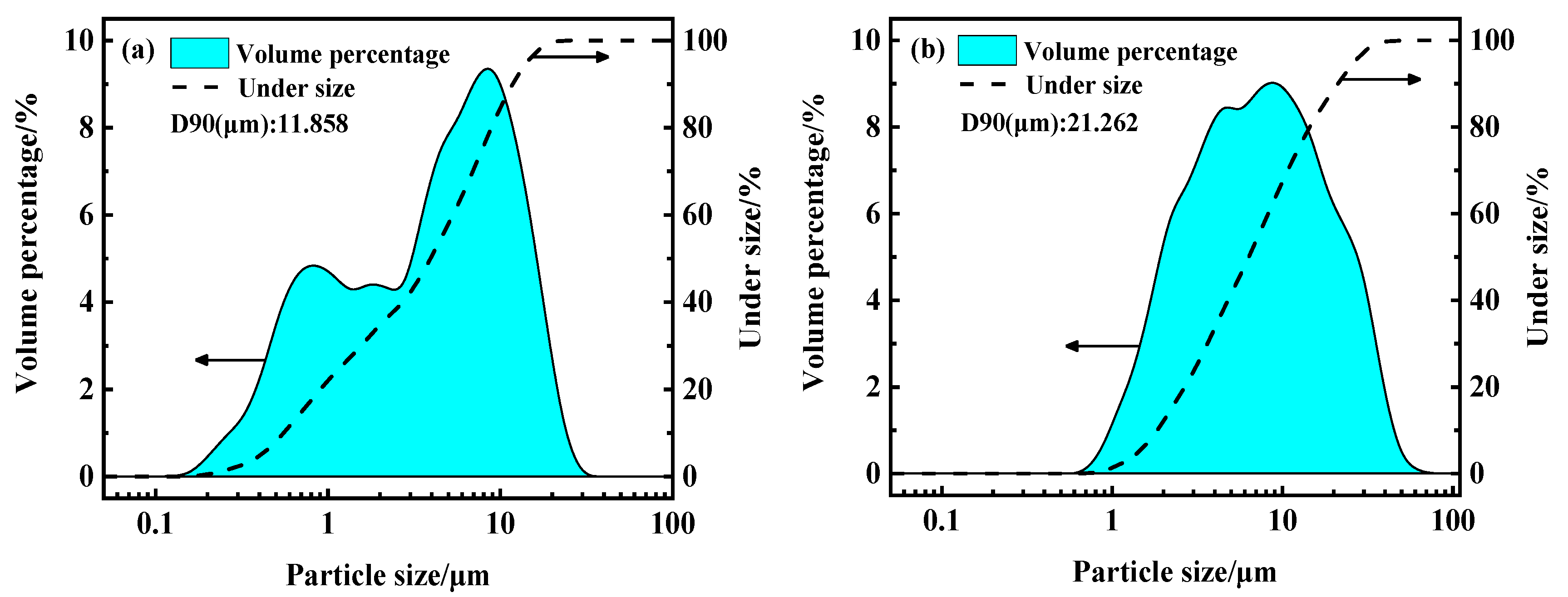
2.1.1. Particle Size Distribution

The particle size of the ground raw materials was determined by a laser particle sizer (LS-609, OMEC, Zhuhai, China). As shown in Figure 1, the D90 particle sizes of these materials are 11.858 and 21.262 μm, respectively, after grinding. The particles of the HS-LZT are smaller than those of the kaolin because the original HS-LZT particles are inherently finer, enabling the ball mill to effectively crush the weakly agglomerated particles. On the other hand, kaolin has the characteristic of being prone to agglomeration, which will make its particle diameter larger.

2.1.2. Chemical Compositions of the Raw Materials

As shown in Table 1, the main components of the HS-LZT include SiO2, Al2O3, CaO, and a small amount of Fe2O3. Among them, the mass fraction of SiO2 is the highest, reaching 72.47%, which belongs to high-silicon type tailings. The main components of kaolin are SiO2 and Al2O3. The mass fraction of SiO2 is the highest, being 66.81%, and the mass fraction of Al2O3 also reaches 18.1%. It is not easy to form an appropriate viscosity and a stable internal skeleton structure during the roasting of ceramsite due to the low content of Al2O3 in the HS-LZT. Therefore, kaolin is selected to adjust the silicon-aluminum ratio of the raw materials. Kaolin can also serve as a binder for the raw materials to form balls. After being added, it can effectively reduce the plasticity of the raw material and improve its ball-forming property [28].

2.1.3. Mineral Composition of Raw Materials

Figure 2a shows that the main phase of the lead-zinc tailings is quartz, with a small amount of calcite. Figure 2b indicates the presence of quartz and kaolinite in the kaolin sample, which can be confirmed by their characteristic diffraction peaks. From the chemical composition of the kaolin (Table 1), its relatively high contents of SiO2 (66.81 wt.%) and Al2O3 (18.1 wt.%) further support the coexistence of quartz and kaolinite.

2.1.4. Detection of Heavy Metal Leaching Concentration in Raw Materials

The heavy metal toxicity leaching test of HS-LZT and kaolin was carried out using the horizontal oscillation method. The measurement results and the identification concentration limits are shown in Table 2. As can be seen from Table 2, the initial contents (mass proportions) of lead and zinc in the lead-zinc tailings are 0.1414% and 0.0801%, respectively. However, the measured leaching concentrations are significantly lower than the limit values required by Chinese national standards (Pb < 5 mg/L, Zn < 100 mg/L), indicating that their leaching properties are low and the environmental risks are controllable. The measured leaching concentrations of Pb and Zn in the kaolin samples are much lower than the limit values.

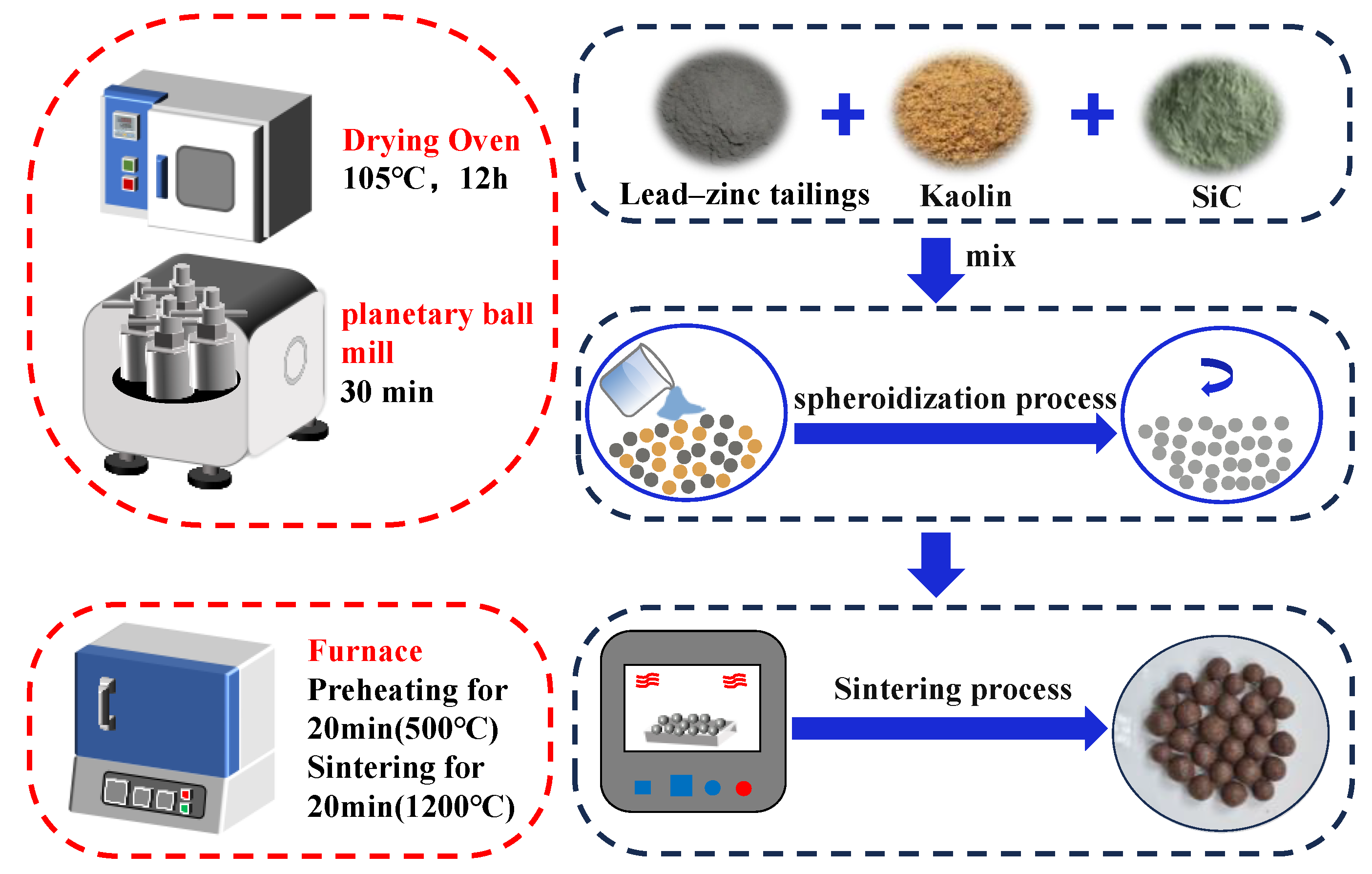
2.2. Preparation of Samples

The HS-LZT ceramsite was prepared by the sintering method. The aim was to make the maximum utilization of HS-LZT, so the mass ratio of HS-LZT was set to be greater than or equal to 60%. The screened raw materials were weighed according to the proportions shown in Table 3 and mixed evenly. Then, an appropriate amount of water was added for manual ball-making, and the diameter was controlled at about 8 mm. After that, the obtained raw material balls were placed in a blast drying oven at 105 ± 5 °C and dried for 12 h. Subsequently, they were transferred to a muffle furnace and sintered at a heating rate of 10 °C/min in the preset heating system. Finally, the ceramsite samples were naturally cooled to room temperature. The preparation flow chart of the HS-LZT ceramsite is shown in Figure 3.

2.3. Characterization and Analytical Methods

The chemical compositions of the raw materials were characterized by an X-ray fluorescence spectrometer (XRF, ZSX Primus III+, Rigaku, Tokyo, Japan). The raw materials and ceramsite samples were characterized by X-ray diffraction using an X-ray diffractometer (XRD, Bruker D8 Advance, Karlsruhe, Germany). The Jade 6.0 analysis software was used to analyze and organize the data to obtain the main phase compositions of the raw materials and ceramsite. The particle sizes of the ground raw materials were detected by a laser particle sizer (LS-609, OMEC, Zhuhai, China). The thermal decomposition behavior of the ceramsite samples was tested by a synchronous thermal analyzer (STA 449C, Netzsch, Selb, Germany). The temperature was increased from 30 °C to 1300 °C at a heating rate of 10 °C/min in an air atmosphere. The macroscopic morphology of the ceramsite samples was observed using a Canon camera (R10, Canon Inc., Tokyo, Japan). The microscopic morphology of the ceramsite products prepared under the optimal conditions was observed using a scanning electron microscope (TESCAN MIRA LMS, Brno, Czech Republic). The leaching toxicity of heavy metals was carried out in accordance with the Chinese standard “Leaching Method for Extracting Toxicity of Solid Wastes-Horizontal Oscillation Method” [29]. Deionized water was used as the extraction solution. The concentrations of Pb and Zn in the leachate were determined by an Agilent 720ES (Agilent Technologies, Santa Clara, CA, USA) inductively coupled plasma optical emission spectrometer (ICP-OES), and the detection limits of both Pb and Zn were 0.01 mg/L.

2.4. Physical Property Tests of Ceramsite

2.4.1. Compressive Strength

According to GB/T17431.2-2010, the confined cylinder method was used to test the compressive strength of ceramsite. However, this method requires a large quantity of ceramsite for the strength measurement. Since the manual ball-making method cannot provide a sufficient amount of ceramsite to meet the requirements of the compressive strength test [30,31], the single-particle bearing capacity of the ceramsite is measured to calculate its compressive strength. There is a good correlation between the single-particle bearing capacity and the cylinder compressive strength of ceramsite, and it can accurately reflect the mechanical properties of the material [32]. Therefore, the compressive strength of the ceramsite in this experiment is also derived by measuring the single-particle failure bearing capacity. A microcomputer-controlled electronic universal testing machine (WDW-50 M, Jinan Kason Testing Equipment Co., Ltd., Jinan, China) was used to test individual ceramsite samples. A single ceramsite sample was placed at the center of the lower platen of the press. The loading rate of the instrument was set to 20 mm/min. After zeroing the pressure value, the instrument was started, and pressure was applied until the ceramsite was broken. The maximum test force Fc when the sample was completely broken under the load was recorded. The particle compressive strength (P) was then calculated using Equation (1):
P = 2.8 F c π D 2
where P is the compressive strength of a single ceramsite, in MPa; Fc is the bearing capacity of the ceramsite, that is, the maximum test force when the ceramsite breaks, in N; and D is the distance between the two loading points, in mm. The final value of each P is the average value of five ceramsite specimens.

2.4.2. Bulk Density

The bulk density was tested in accordance with GB/T17431.2-2010 [33]. The bulk density can be used to calculate the porosity of the ceramsite, thereby determining the density grade of the ceramsite and deciding its applicable scope. The bulk density (ρ) of the ceramsite was calculated using Equation (2):
ρ = ( m t m r ) × 1000 V
where ρ is the bulk density of the ceramsite, in kg/m3; mt is the total mass of the ceramsite sample and the measuring cylinder, in kg; mr is the mass of the measuring cylinder, in kg; and V is the volume of the measuring cylinder, in L.

2.4.3. Water Absorption Rate

The 1h water absorption rate was tested in accordance with GB/T17431.2-2010 [33]. The water absorption rate was mainly determined by the size of the internal pores of the ceramsite. Each experiment was repeated three times to ensure the reliability of the statistical data, and the final experimental result is represented by the arithmetic mean of the three test values. The 1h water absorption rate ( ω ) of the ceramsite was calculated according to Equation (3):
ω = m 2 m 1 m 1 × 100 %
where ω is the 1 h water absorption rate of the ceramsite, in %; m1 is the dry weight of the ceramsite, in g; and m2 is the mass of the ceramsite after being soaked in water for 1 h, in g.

3. Results and Discussion

3.1. Thermal Behavior Analysis of Raw Materials (TG-DSC)

The thermogravimetric-differential scanning calorimetry (TG-DSC) curves of the HS-LZT and kaolin are shown in Figure 4. According to the analysis of Figure 4a, within the temperature range of 30 °C to 1300 °C, the total mass loss of the HS-LZT is 8.471%. It can be specifically divided into three stages: (1) In the temperature range of 30 °C to 523.4 °C, the mass loss is 0.734%, which is mainly attributed to the removal of adsorbed water and crystal water, and a small endothermic peak appears at 232.4 °C; (2) In the temperature range of 523.4 °C to 782.8 °C, the mass loss rate accelerates, increasing from 0.734% to 3.974%, accompanied by a slight endothermic peak; (3) In the temperature range of 782.8 °C to 1300 °C, the mass further decreases by 3.763%. According to the analysis of Figure 4b, within the temperature range of 30 °C to 1300 °C, the total mass loss of kaolin is 10.884%, and the weight loss is more significant. Its thermal behavior can be divided into three stages: (1) In the temperature range of 30 °C to 365.11 °C, the weight loss is 1.385%, mainly caused by the volatilization of free water and adsorbed water; (2) In the temperature range of 365.11 °C to 778.31 °C, the mass loss rate increases significantly, reaching 6.009%, and a slight endothermic peak appears at 751.71 °C; (3) In the temperature range of 778.31 °C to 1300 °C, the mass further decreases by 3.49%.
The thermal behavior of the HS-LZT indicates that the mass loss in the low-temperature stage (30 °C to 523.4 °C) is related to the desorption of water, and the endothermic peak at 232.4 °C may correspond to the dehydration or phase transition process of certain minerals. The rapid weight loss and the endothermic peak in the temperature range of 523.4 °C to 782.8 °C may be related to the decomposition of calcite (CaCO3), while the mass loss in the high-temperature stage (782.8 °C to 1300 °C) may result from the formation of the molten phase and the escape of volatile components. The weight loss behavior of kaolin is closely related to its mineral composition. The weight loss in the range of 30 °C to 365.11 °C is mainly caused by the removal of surface water and interlayer water, while the severe weight loss in the range of 365.11 °C to 778.31 °C is attributed to the removal of structural hydroxyl groups (OH-) (i.e., the dehydroxylation reaction of kaolin), the combustion and decomposition of organic matter, and the thermal decomposition of carbonate minerals. The endothermic peak at 751.71 °C further confirms the structural transformation of kaolin within this temperature range.

3.2. Optimization of the Properties of Prepared Ceramsite

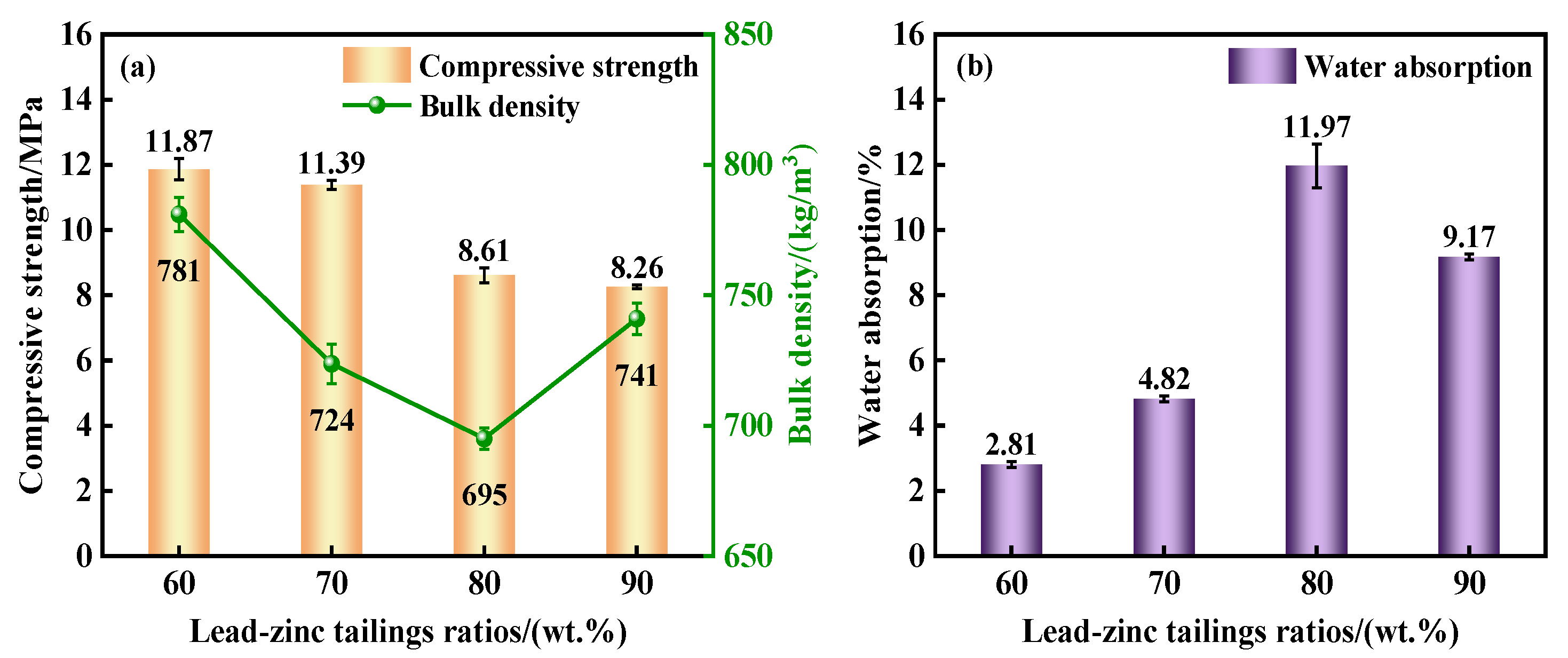
3.2.1. Influence of HS-LZT Ratios on the Properties of Ceramsite

During the preparation process of the ceramsite, the preheating temperature was set at 500 °C, the preheating time was 20 min, the sintering temperature was 1200 °C, the sintering time was 20 min, the external addition amount of SiC was 0.5% [m(SiC)/m(materials), the same below], and the heating rate was 10 °C/min. Experiments were carried out under the conditions where the ratios of HS-LZT were 60%, 70%, 80%, and 90%, respectively, to explore the influence of the HS-LZT ratios on the properties of the ceramsite. The macroscopic morphology of the ceramsite cross-section under different HS-LZT ratios is shown in Figure 5, and the compressive strength, bulk density, and water absorption rate of the ceramsite samples are shown in Figure 6.
As shown in Figure 5, when the raw material ratio (the mass percentage of HS-LZT to kaolin) changes from 6:4 to 9:1, the average pore diameter of the internal pores of the ceramsite first increases and then decreases. As shown in Figure 6, as the ratios of HS-LZT increase from 60% to 90%, the bulk density of the ceramsite first decreases and then increases and reaches the minimum value (695 kg/m3) when the ratio of HS-LZT is 80%. The compressive strength gradually decreases, dropping from 11.87 MPa to 8.26 MPa, while the water absorption rate first increases and then decreases, reaching the peak value (11.97%) when the ratio of HS-LZT is 80%.
Combining with the macroscopic test analysis, the reason for this change may be as follows: When the HS-LZT is gradually added, the contents of SiO2 and CaO increase, the aggregate skeleton becomes denser, and the sintering property of the system improves. The amount of liquid phase formed by the materials at a high temperature continuously increases, and the viscosity of the liquid phase decreases so that more of the generated gas is retained and the amount of gas escaping decreases. The pressure of the retained gas increases sharply, resulting in a good expanded and porous effect of the aggregate; the bulk density decreases, and the compressive strength also decreases accordingly. When the ratio of HS-LZT is 80%, although the bulk density reaches the minimum value, the water absorption rate is the largest, but does not meet the requirements of high-strength ceramsite [34]. As the ratio of HS-LZT increases to 90%, the relative content of HS-LZT is relatively high, and the system generates more liquid phases with too-low viscosity. Therefore, the pores will be filled with the liquid phase, resulting in the collapse of the pore structure and the decrease in porosity, thus increasing the compressive strength and bulk density [35]. When the ratio of HS-LZT is 70%, the foaming effect inside the ceramsite is good, the compressive strength is high, and the bulk density and water absorption rate are low. Therefore, the appropriate amount of HS-LZT is selected to be 70%.
Luo et al. [26] prepared ceramsite using low-silicon lead-zinc tailings (with a SiO2 content of 3.52%). The optimal compressive strength of the ceramsite they obtained was only 7.59 MPa, which is significantly lower than the 11.39 MPa achieved under the optimized conditions in this study. This can be attributed to the fact that high-silicon tailings (with a SiO2 content greater than 72%) have a stronger ability to form a silicon-aluminum skeleton, which effectively improves the mechanical properties.

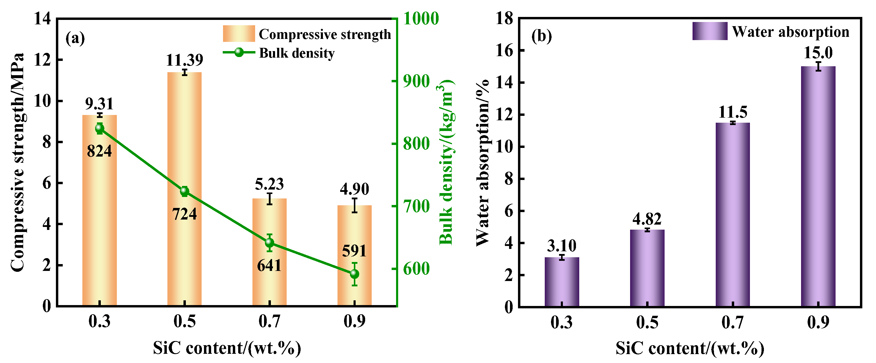
3.2.2. Influence of the External Addition Amount of SiC on the Properties of Ceramsite

The ratio of HS-LZT was selected to be 70%, the preheating temperature was 500 °C, the preheating time was 20 min, the sintering temperature was 1200 °C, the sintering time was 20 min, and the heating rate was 10 °C/min. Experiments were carried out under the conditions where the external addition amounts of SiC were 0.3%, 0.5%, 0.7%, and 0.9%, respectively, to explore the influence of the external addition amount of SiC on the physical properties of the ceramsite. The macroscopic morphology of the ceramsite cross-section under different external addition amounts of SiC is shown in Figure 7, and the compressive strength, bulk density, and water absorption rate of the ceramsite samples are shown in Figure 8.
As shown in Figure 7, when the external addition amount of SiC increases from 0.3% to 1%, more, larger, and irregular pores are generated inside the ceramsite. In addition, large pores with a relatively large depth begin to appear in the middle of the ceramsite. As can be seen from Figure 8, as the external addition amount of SiC increases between 0.3% and 0.9%, the bulk density of the ceramsite decreases from 824 kg/m3 to 591 kg/m3, and the compressive strength shows a trend of first increasing and then decreasing, reaching the peak value (11.39 MPa) when the external addition amount of SiC is 0.5%. In addition, the water absorption rate increases from 3.1% to 15%.
When the external addition amount of SiC is 0.3%, under high-temperature conditions, due to the lack of a sufficient gas source in the green ceramsite balls, the foaming effect inside the ceramsite is not ideal. In this case, the ceramsite shows a relatively high compressive strength and a low water absorption rate, but its bulk density is relatively large. In addition, the SiC particles may not be uniformly dispersed in the ceramsite matrix, resulting in the enrichment or absence of SiC in local areas. This kind of inhomogeneity may give rise to microscopic defects (such as pores or cracks), thus significantly reducing the compressive strength, even though the water absorption rate and bulk density do not exhibit obvious abnormalities. The macroscopic morphology in Figure 7a may show a rougher cross-sectional structure, indicating an uneven pore distribution, which is directly related to the decrease in strength. Therefore, when the addition amount of SiC is low, it is not conducive to the preparation of lightweight and high-strength ceramsite [34]. When the external addition amount of SiC exceeds 0.5%, with the increase in the content of the pore-forming agent, the amount of high-temperature gas generated inside the ceramsite increases, so that the internal liquid phase can encapsulate more gas, generating more pores. Some bubbles even merge or burst, thus forming large pores, ultimately leading to a decrease in the compressive strength and bulk density. At the same time, the gas generated inside the ceramsite will also migrate from the matrix to the surface of the particles, leaving voids on the surface of the particles, resulting in a sharp increase in the water absorption rate. Therefore, it does not meet the requirements of high-strength ceramsite. When the addition ratio of SiC is 0.5%, the foaming condition inside the ceramsite is the best, with a relatively high porosity, a moderate pore size, and a uniform distribution. At this time, the ceramsite not only has a relatively high compressive strength but also has a small bulk density, and the water absorption rate is also maintained at a relatively low level. Therefore, comprehensively considering various performance indicators, the appropriate external addition amount of SiC is selected to be 0.5%.
Peng et al. [27] found that when the addition amount of low-silicon tailings (with a SiO2 content of 16.34%) was 50%, the compressive strength was 9.9 MPa. However, in this study, by introducing a SiC pore-forming agent, the strength was further increased to 11.39 MPa, which reflects the advantages of the synergistic effect between the high-silicon system and the pore-forming agent.

3.2.3. Influence of Sintering Temperature on the Properties of Ceramsite

During the preparation process of the ceramsite, the content of HS-LZT was set at 70%, the preheating temperature was 500 °C, the preheating time was 20 min, the external addition amount of SiC was 0.5% [m (SiC)/m (raw materials)], the heating rate was 10 °C/min, and the sintering time was 20 min. Experiments were conducted at sintering temperatures of 1160 °C, 1180 °C, 1200 °C, and 1220 °C, respectively, to investigate the influence of the sintering temperature on the physical properties of the ceramsite. The macroscopic morphology of the ceramsite cross-sections at different sintering temperatures is shown in Figure 9, and the compressive strength, bulk density, and water absorption rate of the ceramsite samples are illustrated in Figure 10.
As shown in Figure 9, the sintering temperature has a substantial impact on the internal pore structure of the ceramsite. As the sintering temperature increases from 1160 °C to 1220 °C, the porosity of the ceramsite gradually increases. At 1220 °C, there are distinct small and large pores in the ceramsite, with a wide distribution of pore sizes, which is detrimental to the strength of the ceramsite [34]. As depicted in Figure 10, when the sintering temperature rises from 1160 °C to 1220 °C, the bulk density of the ceramsite decreases from 946 kg/m3 to 638 kg/m3, the compressive strength drops from 15.11 MPa to 7.4 MPa, and the water absorption rate increases from 3.6% to 8.66%.
When the sintering temperature is too low, such as 1160 °C and 1180 °C, the amount of liquid phase generated inside the ceramsite is small, and the viscosity of the system is high. The pore-forming agent has little effect on the formation of pores, and the ceramsite structure is relatively dense. At this time, although the compressive strength is high and the water absorption rate is low, the bulk density is also high. When the sintering temperature is 1220 °C, due to the excessively high temperature, the internal foaming of the ceramsite is overly sufficient, leading to a significant decrease in both the bulk density and the compressive strength. Moreover, the number of micropores on the surface of the ceramsite increases, causing a sharp rise in the water absorption rate. The optimal sintering temperature is determined to be 1200 °C by taking all performance indicators into comprehensive consideration.

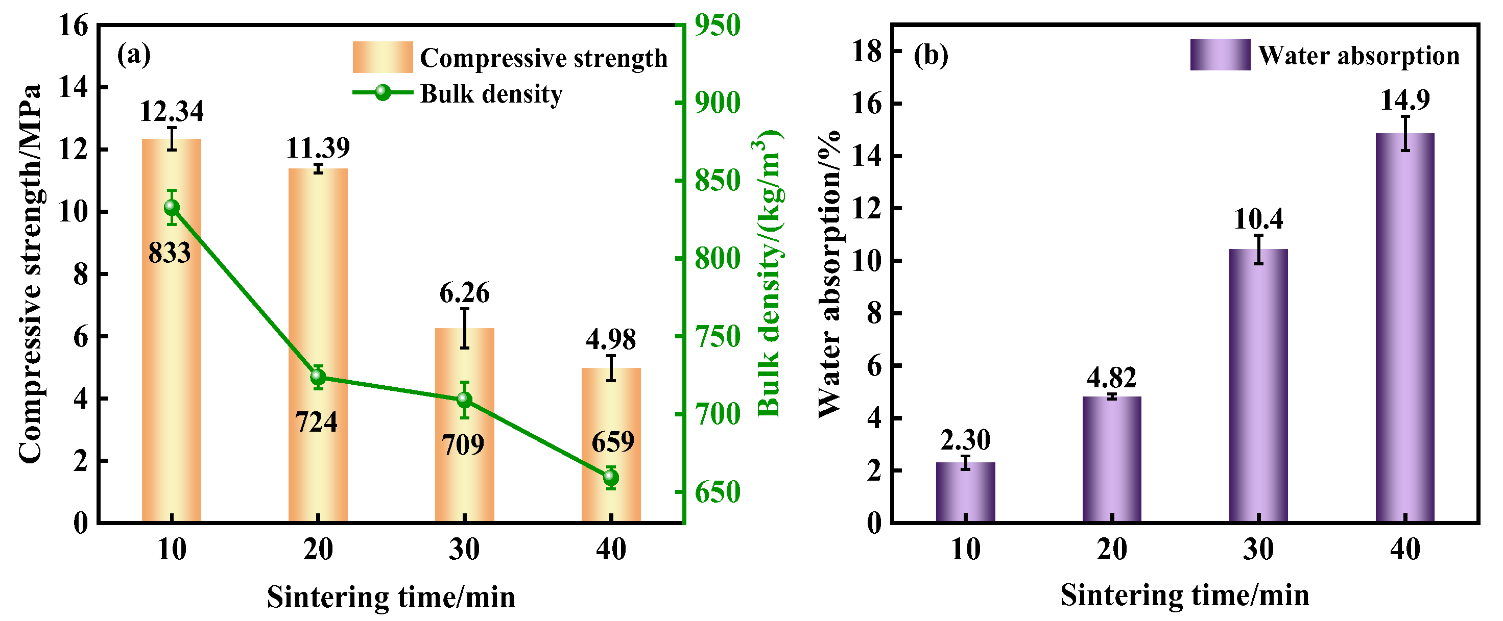
3.2.4. Influence of Sintering Time on the Properties of Ceramsite

During the sintering process of the ceramsite, in addition to the significant influence of the sintering temperature on its properties, the sintering time also plays a crucial role. An appropriate sintering time can maintain good development of the micro-pores inside the ceramsite. The content of HS-LZT was selected to be 70%, the preheating temperature was 500 °C, the preheating time was 15 min, the external addition amount of SiC was 0.5%, and the heating rate was 10 °C/min. Then, the ceramsite was sintered at 1200 °C for 10, 20, 30, and 40 min, respectively to explore the influence of the sintering time on the physical properties of the ceramsite. The macroscopic morphology of the ceramsite cross-section under different HS-LZT contents is shown in Figure 11, and the compressive strength, bulk density, and water absorption rate of the ceramsite samples are shown in Figure 12.
As shown in Figure 11, the sintering time also has a great influence on the internal pore structure of the ceramsite. When the sintering time is extended from 10 min to 40 min, the average pore diameter of the internal pores of the ceramsite increases successively, and the porosity increases. As shown in Figure 12, with the extension of the sintering time, the bulk density of the ceramsite decreases from 833 kg/m3 to 659 kg/m3, the compressive strength decreases from 12.34 MPa to 4.98 MPa, and the water absorption rate changes significantly, increasing from 2.3% to 14.9%.
This is because extending the sintering time will reduce the compressive strength and bulk density of the ceramsite, and, at the same time, it will also increase the energy consumption during the sintering process of the ceramsite. Therefore, the preparation time of the lightweight aggregate ceramsite should not be too long. With the increase in sintering time, the pore-forming agent continuously generates gas, the internal porosity of the ceramsite increases, the ceramsite keeps expanding, and the volume of a single ceramsite particle becomes larger, ultimately reducing the bulk density. In addition, with the extension of the sintering time, the internal pores become larger (Figure 11), and the number of micro-pores on the surface of the ceramsite increases, resulting in a gradual decrease in the compressive strength and a significant increase in the water absorption rate. When the sintering time is 20 min, the internal porosity of the ceramsite is relatively high, the pore size is moderate, and the distribution is uniform. At this time, the ceramsite not only has a relatively high compressive strength but also has a small bulk density, and the water absorption rate is also maintained at a relatively low level. Therefore, comprehensively considering various performance indicators, the optimal sintering time is selected to be 20 min.

3.3. Characterization of the Optimal Ceramsite

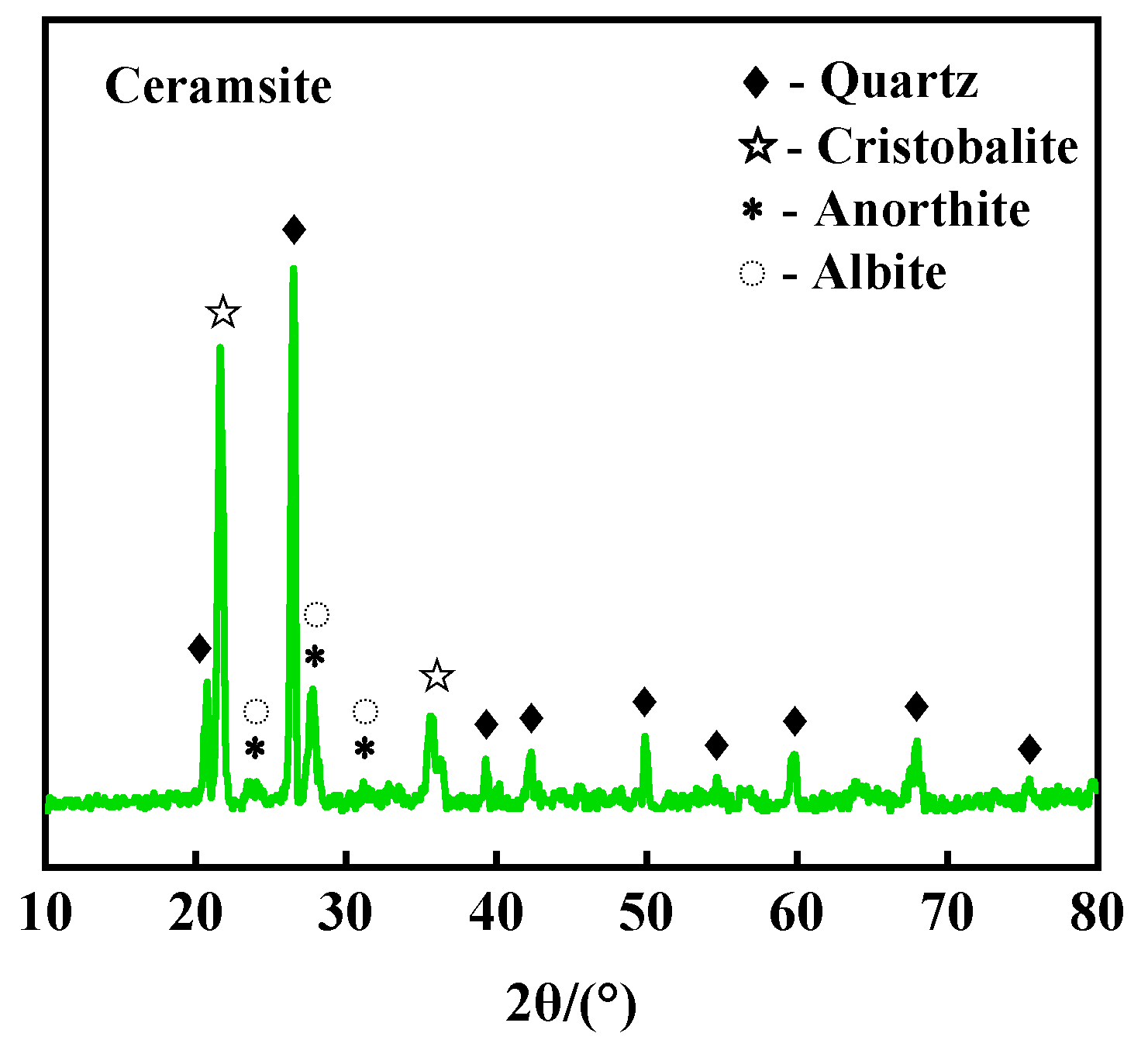
3.3.1. X-Ray Diffraction (XRD) Analysis

Figure 13 shows the XRD pattern of the ceramsite fired under the optimal scheme. It can be observed from the pattern that the main crystalline phases constituting the pore walls of the ceramsite include quartz, cristobalite, anorthite, and albite. The crystalline phase can effectively improve the compressive strength of the ceramsite [30].

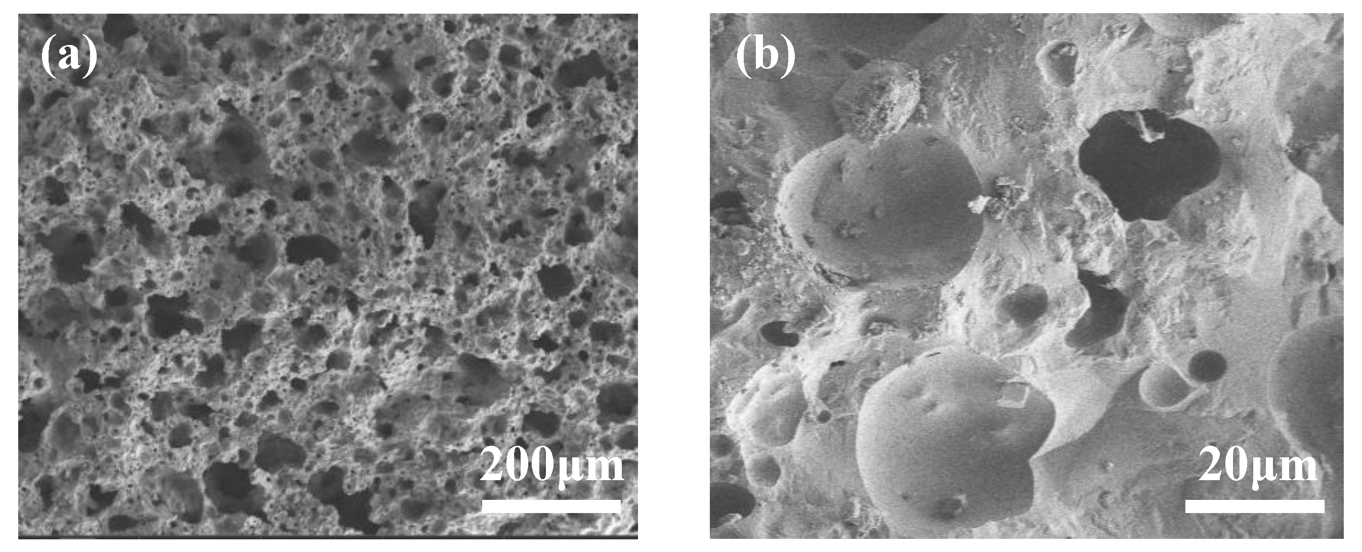
3.3.2. Scanning Electron Microscope (SEM) Analysis

Figure 14 shows the microscopic structure of the cross-section of the ceramsite fired under the optimal scheme. As shown in Figure 14a, not only does the inside of the ceramsite have a large number of pores and a high porosity, but it also exhibits a regular and uniform pore structure. Combined with the physical property test results of the ceramsite under the optimal scheme, this indicates that the regular and uniform pore structure is conducive to improving the compressive strength of the ceramsite [35]. As shown in Figure 14b, the ceramsite shows an ideal isolated pore structure. Some isolated pores are connected to each other, while most of the pores are semi-closed. The thickness of the pore walls is relatively uniform, and there are fewer micro-pores inside the pore walls, which also improves the compressive strength of the ceramsite [30]. In addition, large pores with a relatively large depth are found, which may be due to the increase in the generation rate and volume of gas during the sintering process, accelerating the formation and growth of the pores. It is also worth noting that the surface of the pores shows a high degree of smoothness, and this characteristic is related to the amorphous glassy phase formed around these voids. Typical quartz crystals and cristobalite (with an irregular polyhedral structure) can be seen on the surface of the pore walls of the ceramsite, which is consistent with the results of the XRD analysis.

3.3.3. Detection of Heavy Metal Leaching Concentration

Table 4 shows the leaching concentrations of Pb and Zn in the ceramsite samples fired under the optimal scheme. As shown in Table 4, the leaching concentrations of both Pb and Zn in the samples sintered at 1200 °C are less than 0.01 mg/L. The results indicate that the sintered ceramsite samples exhibit a good solidification effect on the heavy metals Pb and Zn. Therefore, the ceramsite samples prepared under the optimal scheme are extremely safe.

4. Conclusions

(1)
The optimal preparation parameters of the HS-LZT ceramsite are as follows: The mass proportion of HS-LZT is 70%, the mass proportion of kaolin is 30%, and the addition amount of (SiC) is 0.5% (the percentage of the mass of SiC in the total mass of the materials). During the sintering process, the temperature in the preheating stage is 500 °C, the preheating time is 20 min, the sintering temperature is set at 1200 °C, the sintering time is 20 min, and the heating rate is 10 °C/min. The reuse method of using a high content of HS-LZT provides a scientific and effective way for its large-scale resource utilization. It not only has potential economic benefits but also meets the requirements for sustainable development with green and low-carbon characteristics.
(2)
The HS-LZT ceramsite prepared under the optimized parameters performed as follows: compressive strength is 11.39 MPa, 1 h water absorption rate is 4.82%, and bulk density is 724 kg/m3, which possessed the excellent performance of lightweight and high strength. The large number of pores inside the ceramsite and the regular and uniform pore structure greatly improve its compressive strength.
(3)
The leaching concentrations of Pb and Zn in the sintered ceramsite samples under the optimal scheme are significantly lower than the limit values of harmful components in the leachate specified by relevant standards. The results indicate that the sintered ceramsite samples exhibit good solidification effects on the heavy metals Pb and Zn.

Author Contributions

Q.H.: formal analysis, investigation, and writing—original draft. M.L.: conceptualization, visualization, and writing—review and editing. C.L.: methodology and data curation. Y.Y.: validation. All authors have read and agreed to the published version of the manuscript.

Funding

This work was supported by the Key Projects of Scientific Research of Hunan Provincial Department of Education (23A0334).

Institutional Review Board Statement

Not applicable.

Informed Consent Statement

Not applicable.

Data Availability Statement

The data presented in this study are available on request from the corresponding author.

Conflicts of Interest

The authors declare no conflict of interest.

References

  1. Maruthupandian, S.; Chaliasou, A.; Kanellopoulos, A. Recycling mine tailings as precursors for cementitious binders-Methods, challenges and future outlook. Constr. Build. Mater. 2021, 312, 125333. [Google Scholar] [CrossRef]
  2. Li, R.; Yin, Z.Y.; Lin, H. Research status and prospects for the utilization of lead-zinc tailings as building materials. Buildings 2023, 13, 150. [Google Scholar] [CrossRef]
  3. Nayak, A.; Jena, M.S.; Mandre, N.R. Beneficiation of lead-zinc ores-a review. Miner. Process. Extr. Metall. Rev. 2022, 43, 564–583. [Google Scholar] [CrossRef]
  4. Li, X.Q.; Meng, D.L.; Li, J.; Yin, H.Q.; Liu, H.W.; Liu, X.D.; Cheng, C.; Xiao, Y.H.; Liu, Z.H. Response of soil microbial communities and microbial interactions to long-term heavy metal contamination. Environ. Pollut. 2017, 231, 908–917. [Google Scholar] [CrossRef]
  5. Wen, L.X.; Tang, P.Y.; Li, W.G. Research progress on comprehensive utilization of lead-zinc tailings as resources. Nonferrous Met. Min. Sect. 2024, 76, 17–22. (In Chinese) [Google Scholar]
  6. Lei, C.; Yan, B.; Chen, T.; Quan, S.X.; Xiao, X.M. Comprehensive utilization of lead-zinc tailings, part 1: Pollution characteristics and resource recovery of sulfur. J. Environ. Chem. Eng. 2015, 3, 862–869. [Google Scholar] [CrossRef]
  7. Shi, C.H.; Liu, M.S.; Cheng, L.J.; Lan, R. Research progress and engineering practice on comprehensive utilization of tailings. China Min. Mag. 2024, 33, 107–114. (In Chinese) [Google Scholar]
  8. Que, Y.; Chen, J.A.; Ma, H.S.; Lin, Y.Q.; Jiang, Z.L. Using soil tuff-modified polymetallic lead-zinc tailings sand to facilitate sustainable development of subgrade engineering. Constr. Build. Mater. 2024, 426, 136128. [Google Scholar] [CrossRef]
  9. Lin, H.; Li, R.; Li, S. Fabrication of Lead-Zinc Tailings Sintered Brick and Its Effect Factors Based on an Orthogonal Experiment. Materials 2024, 17, 2352. [Google Scholar] [CrossRef]
  10. Sun, R.G.; Gao, Y.; Yang, Y. Leaching of heavy metals from lead-zinc mine tailings and the subsequent migration and transformation characteristics in paddy soil. Chemosphere 2022, 291, 132792. [Google Scholar] [CrossRef]
  11. Ding, X.H.; Luo, B.; Zhou, H.T.; Zhou, H.T.; Chen, Y.H. Generalized solutions for advection–dispersion transport equations subject to time-and space-dependent internal and boundary sources. Comput. Geotech. 2025, 178, 106944. [Google Scholar] [CrossRef]
  12. Saedi, A.; Jamshidi-Zanjani, A.; Mohseni, M.; Darban, A.K.; Nejati, H. Mechanical activation of lead-zinc mine tailings as a substitution for cement in concrete construction. Constr. Build. Mater. 2023, 364, 129973. [Google Scholar] [CrossRef]
  13. Lin, H.; Yin, Z.Y.; Li, S. Optimization of cementitious material with thermal-activated lead-zinc tailings based on response surface methodology. Materials 2024, 17, 2926. [Google Scholar] [CrossRef]
  14. Su, Y.H.; Luo, B.; Luo, Z.D.; Xu, F.; Huang, H.; Long, Z.W.; Shen, C.P. Mechanical characteristics and solidification mechanism of slag/fly ash-based geopolymer and cement solidified organic clay: A comparative study. J. Build. Eng. 2023, 71, 106459. [Google Scholar] [CrossRef]
  15. Liu, Q.; Li, Y.; Zhao, G. The latest research progress of green building materials in lead and zinc tailings. IOP Conf. Ser. Earth Environ. Sci. 2019, 267, 052024. [Google Scholar] [CrossRef]
  16. Wang, H.J.; Ju, C.X.; Zhou, M.; Zheng, F.; Dong, Y.Q.; Hou, B.B.; Liu, S.H. Grinding kinetics of lead-zinc tailing powders and its optimal particle size as a pozzolanic admixture in cement mortar. Adv. Powder Technol. 2022, 33, 103730. [Google Scholar] [CrossRef]
  17. Akkaya, U.G.; Cinku, K.; Yilmaz, E. Characterization of strength and quality of cemented mine backfill made up of lead-zinc processing tailings. Front. Mater. 2021, 8, 740116. [Google Scholar] [CrossRef]
  18. Zhao, L.; Zhang, G.F.; Wang, M.T.; Zhen, S.Y. Preparation of high-purity vaterite CaCO3 from lead-zinc tailings. Sustain. Chem. Pharm. 2022, 29, 100835. [Google Scholar] [CrossRef]
  19. Liao, S.X.; Zhao, Z.M.; Wu, L.; Quan, S.C.; Liu, Z.; Wang, C.; Cheng, J.C.; Zhang, Z.Q. Effects of lightweight ceramsite on heat insulation performance of phosphorus gypsum. New Build. Mater. 2021, 48, 142–145. (In Chinese) [Google Scholar]
  20. Fan, L.F.; Wang, H.; Zhong, W.L. Development of lightweight aggregate geopolymer concrete with shale ceramsite. Ceram. Int. 2023, 49, 15422–15433. [Google Scholar] [CrossRef]
  21. Shen, T.Y.; Yang, Y.; Yu, H.H.; Wang, P.; Xu, P. Enhancement mechanism of the DBDP self-Fenton-like system by lightweight fly ash ceramsite: Pore-making and electron transfer with CoFe-LDO. Chem. Eng. J. 2024, 488, 151126. [Google Scholar] [CrossRef]
  22. Ou, C.J.; Wang, J.Y.; Yang, W.X.; Bao, Y.Q.; Liao, Z.P. Removal of ammonia nitrogen and phosphorus by porous slow-release Ca2+ ceramsite prepared from industrial solid wastes. Sep. Purif. Technol. 2023, 304, 122366. [Google Scholar] [CrossRef]
  23. Pei, J.N.; Pan, X.L.; Lv, Z.Y.; Yu, H.Y.; Tu, G.F. Synergistic mechanism to prepare ultra-lightweight ceramsite using multiple industrial solid wastes. Constr. Build. Mater. 2024, 425, 136139. [Google Scholar] [CrossRef]
  24. Shi, X.F.; Geng, C.; Li, Q.M.; Wei, J.; Chu, Y.Y. A novel application for magnetite tailings and municipal sludge in ceramsite preparation. Environ. Prog. Sustain. Energy 2024, 43, e14239. [Google Scholar] [CrossRef]
  25. Xiao, T.T.; Fan, X.Y.; Wang, H.R.; Zeng, Z.L.; Tian, Z. Removal of phosphorus from water bodies using high-performance ceramsite prepared from solid wastes. Sep. Purif. Technol. 2024, 342, 126962. [Google Scholar] [CrossRef]
  26. Luo, Z.T.; Guo, J.Y.; Liu, X.H.; Mu, Y.D.; Zhang, M.X. Preparation of ceramsite from lead-zinc tailings and coal gangue: Physical properties and solidification of heavy metals. Constr. Build. Mater. 2023, 368, 130426. [Google Scholar] [CrossRef]
  27. Peng, H.T.; Wang, D.; Sofi, M.; Mendis, P.; Zhou, Z.Y.; Liu, J.L. Feasibility of Using lead-zinc tailings to Produce Environmentally Friendly Ceramisite. J. Mater. Civ. Eng. 2021, 33, 04021298. [Google Scholar] [CrossRef]
  28. Li, Y.; Zhao, W.; Zhang, X.H.; Wang, R.; Yan, B.J.; Guo, H.W. Study on preparation of high-strength ceramsite from fluorite tailings and its properties. Inorg. Chem. Ind. 2023, 55, 100–108. (In Chinese) [Google Scholar]
  29. GB 5085.3-2007; Identification Standards for Hazardous Wastes-Identification for Extraction Toxicity. Standards Press of China: Beijing, China, 2007.
  30. Xiao, T.T.; Fan, X.Y.; Zhou, C.Y.; Wang, H.R.; Wu, K.X.; Zhou, H. Preparation of ultra-lightweight ceramsite from waste materials: Using phosphate tailings as pore-forming agent. Ceram. Int. 2024, 50, 15218–15229. [Google Scholar] [CrossRef]
  31. Yashima, S.; Kanda, Y.; Sano, S. Relationships between particle size and fracture energy or impact velocity required to fracture as estimated from single particle crushing. Powder Technol. 1987, 51, 277–282. [Google Scholar] [CrossRef]
  32. Tay, J.H.; Hong, S.Y.; Show, K.Y. Reuse of industrial sludge as pelletized aggregate for concrete. J. Environ. Eng. 2000, 126, 279–287. [Google Scholar] [CrossRef]
  33. GB/T17431.2-2010; Lightweight Aggregates and Its Test Methods—Part 2: Test Methods for Light-Weight Aggregates. China Standard Press: Beijing, China, 2010. (In Chinese)
  34. GB/T17431.1-2010; Lightweight Aggregates and Its Test Methods—Part 1: Lightweight Aggregates. China Standard Press: Beijing, China, 2010. (In Chinese)
  35. Guo, P.H.; Zhao, Z.K.; Li, Y.K.; Zhang, Y.B.; He, T.; Hou, X.M.; Li, S.Q. Co-utilization of iron ore tailings and coal fly ash for porous ceramsite preparation: Optimization, mechanism, and assessment. J. Environ. Manag. 2023, 348, 119273. [Google Scholar] [CrossRef]
Figure 1. Particle size distribution of raw materials after grinding: (a) HS-LZT; (b) Kaolin.
Sustainability 17 04523 g001
Figure 2. XRD patterns of raw materials: (a) HS-LZT; (b) Kaolin.
Sustainability 17 04523 g002
Figure 3. Flowchart showing preparation process of HS-LZT ceramsite.
Sustainability 17 04523 g003
Figure 4. TG-DSC patterns of raw materials. (a) HS-LZT; (b) Kaolin.
Sustainability 17 04523 g004
Figure 5. Macroscopic morphology images of ceramsite cross-sections at different HS-LZT ratios. (a) 6:4; (b) 7:3; (c) 8:2; (d) 9:1.
Sustainability 17 04523 g005
Figure 6. Properties of ceramsite at different HS-LZT ratios. (a) Compressive strength and bulk density; (b) Water absorption rate.
Sustainability 17 04523 g006
Figure 7. Macroscopic morphology images of ceramsite cross-sections at different SiC additives. (a) 0.3%; (b) 0.5%; (c) 0.7%; (d) 0.9%.
Sustainability 17 04523 g007
Figure 8. Properties of ceramsite at different SiC additives. (a) Compressive strength and bulk density; (b) Water absorption rate.
Sustainability 17 04523 g008
Figure 9. Macroscopic morphology images of ceramsite cross-sections at different sintering temperatures. (a) 1160 °C; (b) 1180 °C; (c) 1200 °C; (d) 1220 °C.
Sustainability 17 04523 g009
Figure 10. Properties of ceramsite at different sintering temperatures. (a) Compressive strength and bulk density; (b) Water absorption rate.
Sustainability 17 04523 g010
Figure 11. Macroscopic morphology images of ceramsite cross-sections at different sintering times. (a) 10 min; (b) 10 min; (c) 10 min; (d) 10 min.
Sustainability 17 04523 g011
Figure 12. Properties of ceramsite at different sintering times. (a) Compressive strength and bulk density; (b) Water absorption rate.
Sustainability 17 04523 g012
Figure 13. XRD pattern of ceramsite produced using the optimum method.
Sustainability 17 04523 g013
Figure 14. SEM images of ceramsite prepared by the optimized process. (a) Magnification of 50×; (b) Magnification of 500×.
Sustainability 17 04523 g014
Table 1. Main chemical compositions of raw materials (w/%).
Raw MaterialsSiO2Al2O3Fe2O3CaOMgONa2OK2OSO3TiO2P2O5LOI
HS-LZT72.479.482.6710.741.460.131.111.140.200.1817.40
Kaolin66.8118.15.70.581.20.523.082.690.370.449.63
Table 2. Contents of Pb and Zn in raw materials and their leached concentrations (mg/L).
Heavy MetalsHS-LZTKaolinConcentration Limits of Harmful Components in Leaching Solution
Pb3.29<0.015
Zn1.87<0.01100
The mass proportion of lead (Pb)0.1414%
The mass proportion of zinc (Zn)0.0801%
Table 3. Ratio of raw materials for ceramsite preparation.
M (HS-LZT)/m (Kaolin)ω (HS-LZT)/%ω (Kaolin)/%[m (SiC)/m (Raw Materials)]/%
6:460400.5
7:370300.5
8:280200.5
9:190100.5
Table 4. Leached concentrations of major heavy metals of ceramsite prepared by the optimized process (mg/L).
Heavy MetalsCeramsiteConcentration Limits of Harmful Components in Leaching Solution
Pb<0.015
Zn<0.01100
Disclaimer/Publisher’s Note: The statements, opinions and data contained in all publications are solely those of the individual author(s) and contributor(s) and not of MDPI and/or the editor(s). MDPI and/or the editor(s) disclaim responsibility for any injury to people or property resulting from any ideas, methods, instructions or products referred to in the content.

