Abstract
In this study, the performance and durability of polymer electrolyte membrane fuel cells (PEMFCs) were improved using a Pt-Pr6O11 composite electrode fabricated through a co-sputtering technique. Platinum (Pt), widely used as the catalyst material in PEMFCs, often faces stability issues under various electrical load conditions. These issues require greater efforts to enhance PEMFC durability. Various approaches, including replacement of catalyst supports with electrically stable materials (such as metal oxides) or adoption of core-shell and alloy structures to stabilize Pt, have been attempted. In this research, a thin film electrode combining Pr6O11 and Pt was fabricated. Pr6O11, a lanthanide oxide, enhances the oxygen reduction reaction (ORR) through strong interactions with Pt, and its multi-valence state contributes to improved durability. Scanning electron microscopy (SEM) and X-ray photoelectron spectroscopy (XPS) were employed to analyze the composition, morphology, and chemical characteristics of the electrodes. I-V curves and electrochemical impedance spectroscopies (EIS) were measured to evaluate electrochemical properties of fuel cells. A cyclic voltammetry (CV) test was conducted to calculate the electrochemical surface area of the cell. As a result, the incorporation of Pr6O11 improved the pristine cell performance by 7.6% and increased performance after degradation testing by 121% compared to Pt-only cases. This demonstrates the effectiveness of the Pt-Pr6O11 composite in enhancing both the initial performance and the durability of PEMFCs.
1. Introduction
As environmental issues became more serious today, there has been more interest in alternative energy generation sources like fuel cells. So, there has been a surge in research and practical applications of fuel cells that produce only pure water and electrical energy during the energy generation [1]. Compared to other alternative energy generation sources, fuel cells have some unique advantages. Firstly, fuel cells have high energy conversion efficiency compared with other energy sources [2]. Furthermore, reversible fuel cells can store the excess energy as hydrogen through a water electrolysis process without pollutants [3,4]. Among the fuel cells, the polymer electrolyte membrane fuel cell (PEMFC), a type of fuel cell that uses a polymer electrolyte membrane, operates at low temperatures (ranging from 60 °C to 85 °C), making it the most widely applied in everyday life.
The performance of the PEMFC electrode is primarily influenced by two key factors. The first factor is the catalytic properties of the electrode. Because the ionization of oxygen and fuel is essential in the fuel cell’s energy generation process, it is important to use highly catalytic materials that require less energy for ionization to increase the fuel efficiency. Platinum (Pt) is widely recognized as the most effective material for oxygen reduction reactions in general PEMFC operating conditions. Because of this property, it is commonly used as the catalyst material in PEMFCs. The second factor is the maximization of the reaction sites. The ionization of fuel occurs only at the triple-phase boundary (TPB), where the catalyst material, fuel, and electrolyte meet. Thus, maximizing TPB ensures that ion production is optimized over the same surface area of the catalyst. Typically, PEMFCs utilize carbon black, a support material with excellent electrical conductivity and a parallel layered structure to maximize the surface area of platinum [1,5].
Although Pt exhibits outstanding catalytic performance, its high cost remains one of the major challenges for commercialization. The most widely used commercial method for producing electrodes is the spray process, which uses Pt/C powder based on carbon black. While carbon black supports efficient catalyst distribution, it is highly sensitive to electrical changes [6,7], which makes it unstable in PEMFC operating conditions. This instability compromises the durability of PEMFC electrodes, leading to higher costs. These issues become particularly pronounced during the start-up and shut-down process of fuel cells [6], where fuel depletion at the anode causes sudden voltage spikes, and local voltage increases due to flooding [8]. At high electrode potentials, carbon becomes unstable, which destroys the structure of the catalyst layer. Unstable catalyst support also can accelerate the growth of platinum particles through Ostwald ripening [9,10,11]. The growth of platinum generally decreases the reaction site, ultimately leading to significant degradation of the fuel cell.
Many studies have been conducted to solve the durability problems of electrodes and maximize electrode performance. A common research direction involves replacing carbon-based support materials with metal oxides, such as TiO2, WOx, and CeOx, to stabilize the catalyst and enhance its activity. It has been reported that TiO2 can increase catalyst activity of platinum and improve the ion transport ability when the PEMFC operates under non-humidified conditions [7,12]. WOx improves the stability of the start–stop condition of PEMFC [6,13], while CeOx can improve the catalytic activity and durability of platinum [11,14,15,16]. Additionally, efforts have been made to reduce the amount of platinum by alloying Pt with other metals, such as Ni [10], Co [17], Pd [18], and Zn [19,20], which increases both the activity and durability of the catalyst. These metals can improve the Pt catalytic activity in PEMFC operation with low platinum contents.
Praseodymium (Pr)-based oxides (PrOx) have also gained attention as materials that enhance catalyst performance through strong interactions with platinum [21,22]. Praseodymium, a lanthanide metal, exhibits a multi-valence state (Pr3+, Pr4+) in its oxide form [23]. This characteristic makes Pr highly oxygen-affinitive and allows PrOx to serve as an oxygen storage reservoir [24]. This oxygen storage capacity (OSC) prevents the poisoning of Pt, which can be caused by impurity radicals potentially generated during PEMFC reactions, and provides activated reactants to otherwise inactive Pt regions [15,16,21]. Furthermore, numbers of studies have shown that the interaction between platinum and metal oxides reduces the lattice distance between platinum particles, thereby promoting catalytic activity and enhancing stability [7,11,12,13,14,15,16].
While research utilizing cerium and its oxides, which are similar characteristics to praseodymium, has been extensively conducted to improve PEMFC electrode performance, fewer studies have focused on praseodymium. In this study, a thin film catalyst was fabricated by co-sputtering praseodymium oxide (Pr6O11) and Pt simultaneously and it was used as the catalyst. The magnetron system was used in this study to improve the performance of the sputtering system. The thin film method produces PEMFC catalyst with nanometer-scale thicknesses, which is significantly thinner than the commercial catalyst layer made by the spray method, which have thicknesses of around 30–40 μm. This nanometer-scale thickness is sufficient to form a triple-phase boundary (TPB) by utilizing the self-expansion of Nafion. Therefore, a separate ionomer application process is not required. This feature makes it easier to produce a catalyst of consistent quality and is advantageous for mass production [14,25].
The experiment aimed to investigate that the effectiveness of Pr6O11 in improving the fuel cell’s performance and durability, where the catalyst’s performance has a dominant influence on the cell efficiency. The performance of fuel cells was measured using linear sweep voltammetry (LSV) to generate I-V curves, and the durability of the catalyst was evaluated based on the accelerated stress test (AST) cycle proposed by the United States department of energy (DoE). Additionally, impedance analysis and electrochemical surface area calculations were conducted using electrochemical impedance spectroscopy (EIS) and cyclic voltammetry (CV), respectively. Scanning electron microscopy (SEM) was employed to analyze the surface morphology of the electrodes. X-ray photoelectron spectroscopy (XPS) was also used to examine the compositional ratio and bonding states of the catalytic materials.
2. Experiments
The electrodes used in the experiment were fabricated by depositing a thin film of catalytic materials on a commercial Gas Diffusion Layer (GDL) (Sigracet 39BB, SGL Carbon Co., Wiesbaden, Germany) using a sputtering technique. Pt was employed as the catalyst material. The sputtering process was conducted using an electromagnetic sputtering system (NEO Sputtering system, JA Innovation, Yongin, Republic of Korea), with a 2-inch platinum target (Vacuum Thin Film Materials, Daegu, Republic of Korea) with 2 mm thickness, and a Pr6O11 target (Vacuum Thin Film Materials, Republic of Korea) of the same specification. During the deposition, the base pressure inside the sputtering chamber was maintained at approximately 9 × 10⁻⁶ Torr. The working deposition environment was kept at room temperature, with pure argon gas (Ar 99.999%, Samjung Energy, Seoul, Republic of Korea) flowing through the system. The working pressure was 15 mTorr.
For the fabrication of the Pt-Pr6O11 cathode, 40 W of direct current (DC) power was applied to the Pt target and, simultaneously, 40 W of radio frequency (RF) power was applied to the Pr6O11 target. The rotation speed of substrates was 4.3 rpm for all samples. For performance comparison at the same Pt loading, a reference cathode was fabricated on GDL by applying 40 W of DC power to the Pt target under the same deposition conditions. In both cases, the thickness of the Pt film was maintained at approximately 120 nm on silicon wafer, with a loading of 0.18 mgpt/cm2. The Pt loading was calculated based on the volume of the deposited Pt on a silicon (Si) wafer and the density of Pt at room temperature. In both experiments, the anode used the same electrode as the cathode of the reference case. During the deposition process, substrates were rotated at 4.3 rpm to ensure uniformity. Therefore, the catalyst was uniformly deposited on the MPL side of GDL with 1 cm × 1 cm surface area. Before deposition, all GDLs were dried in an 80 °C oven for at least 12 h to ensure the quality and uniformity of the films.
To examine the effect of Pr6O11 on the durability of PEMFCs, two types of cells were fabricated and compared. The reference case and the Pt-Pr6O11 case. Both cells used the same anode electrode as in the reference case’s cathode. The active area was 1 cm2, and a commercial bipolar plate (CNL Energy, Samcheok, Republic of Korea) with a single-channel serpentine flow field was used. The sputtered GDLs were combined with a Nafion 212 membrane (DuPont Co., Wilmington, DE, USA) as the electrolyte. The specific layout of the cell is illustrated in Figure 1. The assembly of the cell was completed with a torque wrench, applying a force of 4 N-m.
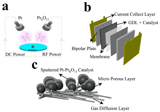
Figure 1.
Schematics of experiments. (a) Sputter process chamber, (b) cell assembly, (c) sputtered Pt-Pr6O11 thin films on GDL.
For the evaluation of electrochemical performance, a commercial PEMFC test station (Smart2 PEM, WONA Tech, Seoul, Republic of Korea), potentiostat (SP-150, Biologic, Seyssinet-Pariset, France), and current booster (VMP3B-10, Biologic, France) were utilized. The fuel cell was operated at a temperature of 70 °C, with fully humidified high-purity hydrogen (>99.999%) and air (N2 80%, O2 20%) supplied at rates of 100 sccm and 200 sccm, respectively. The electrochemical performance was assessed using current–voltage (I-V) measurements and electrochemical impedance spectroscopy (EIS) analysis.
For the I-V measurement, linear sweep voltammetry (LSV) was conducted at a scan rate of 5.0 mV/sec, starting from the open-circuit voltage (OCV) down to 0.3 V. The EIS analysis was performed under a load of 0.5 V, with a frequency range of 100 mHz to 200 kHz, and a sinusoidal amplitude of 10 mV applied during the measurement. A cyclic voltammetry (CV) test was also conducted to compare the active electrochemical reaction area (ECSA) of Pt cathode and Pt-Pr6O11 cathode. Active area cells of 5 cm2 were used for CV testing to minimize the curve noise due to the uneven flow. All the properties were the same as the other test cell but the only difference was the scale. CV tests were performed with 100 sccm of H2 and 200 sccm of N2 flow at the anode and cathode, respectively. The voltage scan rate was 30 mV/s and the scan range was 0.05 V to 1.4 V.
To test the durability of the catalyst layer, an accelerated stress test (AST) was conducted. The AST cycle was performed a total of 10,000 times. During the AST cycle, the voltage was cycled between 0.6 V and 0.9 V. A rest period of 3 s was provided at both 0.6 V and 0.9 V, and the voltage sweep between these two values was carried out at a rate of 100 mV/s. The accelerated stress test followed the protocols established by the Department of Energy (DoE), USA, for PEMFC durability testing.
3. Results and Discussion
Surface images of thin films deposited by the sputtering technique are shown in Figure 2. Before deposition of the catalyst on MPL, an Si wafer was used to obtain the deposition rate of thin films. After calculation of the deposition rate, the same thickness of Pt and Pt-Pr6O11 films were fabricated on MPL. The deposition rate of platinum is 8 nm/min. Figure 2a illustrates SEM images of Pt thin films on Si wafer. Figure 2b shows Pt thin films fabricated on MPL. Pt thin films show a dense and columnar structure on Si wafer. But, on the MPL, Pt shows an island-like structure. We think that the rough and complicated surface of MPL caused this structure. Figure 2d presents sputtered Pt-Pr6O11 thin films on Si wafer and Figure 2e shows Pt-Pr6O11 thin films on MPL. Similar to results of Pt, Pt-Pr6O11 on Si wafer shows a dense and columnar structure. Pt-Pr6O11 also presents an island-like structure on MPL because of similar reasons. Figure 2c,e shows SEM-EDS (Energy Dispersive X-ray Spectroscopy) results of Pt-Pr6O11 thin films on Si wafer. Figure 2e is the result of Pt and Figure 2c is the result of Pr, respectively. As Figure 2c,e presents, both Pt and Pr were evenly distributed by the co-sputtering process. A cross-section image of bare MPL is shown in Figure 2g. It shows unevenly distributed particles with pores. Figure 2h,i show cross-section images of sputtered MPL. Sputtered materials are Pt and Pt-Pr6O11, respectively. They also show evenly sputtered film on the MPL. All films are deposited at the same conditions.
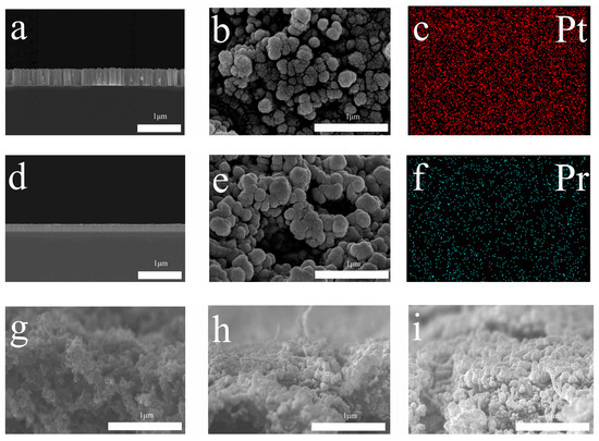
Figure 2.
SEM and SEM-EDS results. (a) Pt thin films on Si wafer, (b) Pt thin films on MPL, (c) Pt mapping of Pt-Pt-Pr6O11 thin films deposited on MPL, (d) Pt-Pt-Pr6O11 thin films on Si wafer, (e) Pt-Pt-Pr6O11 thin films on MPL, (f) Pr mapping of Pt-Pr6O11 films on MPL, (g) bare MPL cross-section, (h) Pt sputtered MPL cross-section, (i) Pt-Pr6O11 sputtered MPL cross-section.
Figure 3 presents the analysis results of sputtered films on Si wafers using X-ray photoelectron spectroscopy analysis. Figure 3a shows the wide peak results representing the full spectrum analysis of sputtered films. For both samples, a peak corresponding to Pt 4f was observed in the 70–76 eV range [14,21]. Additionally, in the Pt-Pr6O11 sample, a Pr 3d peak was clearly observed in the 920–950 eV range, confirming the presence of praseodymium in the fabricated electrode [26]. A quantitative comparison of intensities revealed that the atomic ratio of Pt to Pr in the co-sputtered sample is 91.4:8.6.
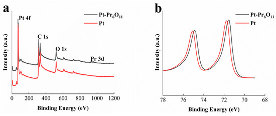
Figure 3.
XPS results of sputtered Pt-Pr6O11 thin films on Si wafer. (a) Peak analysis results, (b) detailed Pt 4f peak.
Figure 3b shows an enlarged view of the 68–78 eV binding energy range, which corresponds to Pt 4f, as seen in Figure 3a. It can be observed that the Pt 4f binding energy in the Pt-Pr6O11 sample has shifted slightly to a lower energy level compared to the Pt-only sample, with a shift magnitude of 0.3 eV. In previous reports, due to the Pt-Pr6O11 interaction, the structure of Pt nanoparticles was reconstructed, resulting in electronic and geometric changes compared to pure Pt nanoparticles [27]. As shown in Figure 2b, one of the results of reconstruction is change of the binding energy of Pt and the low shifted binding energy means the electrons are donated from Pr6O11 to the Pt nanoparticles [27,28]. This shift to a lower binding energy level for Pt 4f indicates that Pt electrons are in a more favorable state for oxygen reduction reaction. Furthermore, change of the binding energy affects the d-band structure of platinum and oxygen adsorption and desorption tendencies [21,29]. The d-band center is the main determining factor of the Pt–oxygen binding structure during the PEMFC activity. If the binding between oxygen molecules and Pt particles is too strong, removing the intermediates during oxygen reduction (O*, OH*) can be difficult. If the binding is too weak, the adsorption ratio of oxygen to Pt can rarely occur and the interaction of Pt-O2 is too weak to induce sufficient reaction [28]. For this reason, optimization of the d-band center of Pt nanoparticles is an important factor of PEMFC activation. Previous research has shown Pt–carbon black has a higher d-band center than the best state of oxygen reduction reaction [27,30]. Many studies have shown the shift places Pt in a more optimized state and successfully reduces energy loss during ORR activity. This reduced energy loss during the adsorption–desorption process also decreases faradaic resistance losses, thereby improving the performance of PEMFC operation [31].
In Figure 4a, the reference case exhibits a peak power density of 185 mW/cm2, whereas the experimental case, Pt-Pr6O11, achieves a peak power density of 199 mW/cm2, showing a 7.6% improvement over the reference case. As seen in Figure 3b, the binding energy of Pt 4f electrons in the Pt-Pr6O11 case is lower than the reference case. This shift affects the d-band structure of the Pt atoms. Change of d-band structure of Pt weakens the adsorption-desorption energy between Pt and the reactants [32]. Also, the improvement in catalytic activity due to the addition of Pr6O11 is shown in the I-V curve of Figure 4a.
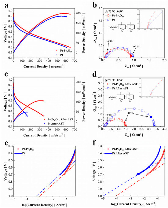
Figure 4.
Performance of PEMFCs. (a) Polarization curves of PEMFCs before AST, (b) Nyquist plots of fuel cells at 0.5 V before AST, (c) polarization curves of PEMFCs after AST, (d) Nyquist plots of fuel cells at 0.5 V after AST, (e) Tafel plots of fuel cells before AST, (f) Tafel plots of fuel cells after AST.
Figure 4 illustrates the electrochemical evaluation of the cells fabricated for this experiment. Figure 4a,b display the I-V-P curves and electrochemical impedance spectroscopy graphs of the cells before the degradation test, while Figure 4c,d show the same measurements after 10 k cycle of accelerated stress test. All the EIS analysis was conducted at a constant bias voltage of 0.5 V. Tafel plots of fuel cells before AST and after AST are illustrated at Figure 4e,f, respectively.
Furthermore, the Pr6O11 multi-valence state provides it with oxygen storage capacity (OSC), enabling praseodymium to supply activated oxygen to Pt. This characteristic supports mass transport at the cathode electrode, supplying fuel to inactive catalyst regions and improving the efficient use of Pt [15,21,33]. This enhancement in electrochemical performance is also presented in the EIS graph. Figure 4b shows the EIS measurements taken at 0.5 V. The ohmic resistance measured for the reference and Pt-Pr6O11 cases were 0.078 ohm·cm2 and 0.071 ohm·cm2, respectively, while the faradaic resistance was 0.895 ohm·cm2 for the reference and 0.857 ohm·cm2 for the Pt-Pr6O11 case. The lower resistance observed in the Pt-Pr6O11 case can be attributed to the change in Pt 4f electron binding energy caused by the presence of Pr6O11, as we mentioned above and illustrated in Figure 3b [21,24,31].
Figure 4c shows the electrochemical performance of the cells after 10 k cycle of AST for catalyst degradation. After AST, the maximum power density of the reference cell decreases to 48 mW/cm2, while maximum power density of Pt-Pr6O11 cell is 106 mW/cm2. The Pt-Pr6O11 cell shows a power density 2.21 times higher than that of the reference cell. Compared to their performance before AST cycle, the maximum performance of the reference cell decreases by 76%, while the Pt-Pr6O11 cell only shows a 46% reduction, highlighting the superior durability of the Pt-Pr6O11 catalyst under accelerated degradation condition of catalyst.
Figure 4d presents the EIS results used to measure the resistance of the cells after AST cycle. The ohmic resistance of both the reference and Pt-Pr6O11 cells slightly increases to 0.084 ohm·cm2, a marginal rise compared to before AST values. However, the faradaic resistance exhibits a significant increase for both cases. The faradaic resistance for the reference case rises dramatically from 0.895 ohm·cm2 to 3.266 ohm·cm2, a 265% increase. In contrast, the Pt-Pr6O11 case shows a more moderate rise from 0.857 ohm·cm2 to 1.386 ohm·cm2, a 61% increase.
The contrast in scale of faradaic resistance increase between the reference (265%) and Pt-Pr6O11 (61%) cases can be explained by the instability of the carbon powder support used in the MPL during the AST cycles. The rapid voltage changes that occur during these cycles make the carbon surface unstable, leading to physical damage or detachment of the carbon layer. This instability also affects the energy state of the platinum catalyst, making it more prone to oxidation or Ostwald ripening, which make the platinum particle size increase, reducing the surface area available for catalytic reactions [34]. This reduction in surface area and the oxidation of platinum decrease the number of active sites, increasing the polarization resistance, which, in turn, negatively impacts fuel cell performance [5,35,36]. To improve durability and avoid the drawback of carbon support, using doped metal oxide and replacing carbon support are effective methods.
The addition of stable oxides like Pr6O11 helps stabilize platinum in such harsh conditions, minimizing Pt loss due to Ostwald ripening. The multi-valence state of praseodymium makes it highly oxygen-affinitive. The multi-valence state of Pr6O11 prevents oxygen radicals from oxidizing and degrading Pt. In addition, Pr6O11 also supplies activated fuel to the electrode [15,21]. These two roles of Pr6O11 reduce the degradation of Pt during fuel cell operation.
As shown in Figure 4b,d, the degradation rate of the reference case is significantly higher compared to the Pt-Pr6O11 case, because of the stabilizing effect of Pr6O11. Based on these results, it is clear that Pr6O11 co-sputtered with Pt stabilizes Pt similar to other oxides, preventing its degradation under electrochemically harsh conditions.
Figure 4e,f present the Tafel plots of fuel cells. Estimated exchange current density from Tafel plot is 5.49 × 10⁻⁴ (A/cm2) in the Pt case. The exchange current density of the Pt-Pr6O11 case is 1.00 × 10⁻³ (A/cm2). This result indicates that the Pr6O11 mixed catalyst has a slightly better catalytic performance, as predicted in Figure 4b [1]. On the other hand, after the AST cycle, estimated exchange current density decreases from 5.49 × 10⁻⁴ (A/cm2) to 1.13 × 10⁻⁵ (A/cm2) in Pt case and from 1.00 × 10⁻³ (A/cm2) to 8.14 × 10⁻⁵ (A/cm2). The difference of exchange current density of Pt-Pr6O11 case is 7.2-fold higher than the Pt case after AST cycle. This gap is larger than the pristine condition and indicates that Pr6O11 can prevent the degradation of PEMFC catalyst performance. This result can also be confirmed through the EIS analysis after AST cycle in Figure 4d.
Figure 5 shows the cyclic voltammetry curve of PEMFCs. The electrochemical surface area was calculated by the following equation. Active area was calculated with H-desorption area at 0.1–0.4 V [37,38].
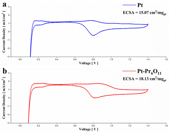
Figure 5.
Electrochemical characteristics of the fuel cell test using CV. (a) Cyclic voltammetry curve of PEMFC using Pt cathode, (b) cyclic voltammetry curve of PEMFC using Pt-Pr6O11 cathode.
The calculated ECSA is 15.07 cm2/mgpt at Pt cell and 18.13 cm2/mgpt at Pt-Pr6O11 cell. It shows 20% higher ECSA of the Pt-Pr6O11 cell. Referring to previous research, metal oxides that interact strongly with Pt can cause better Pt dispersion [15,21]. The oxygen storage capacity of PrOx can provide oxygen for reaction site [15,24].
Figure 6 presents the bar graph illustrating the changes in electrochemical performance of the reference and Pt-Pr6O11 cells before and after the accelerated stress test, as seen in Figure 4. In terms of maximum power density, the Pt-Pr6O11 cell exhibits a 7.6% higher performance before AST and a remarkably higher performance (121%) after AST compared to the reference cell.
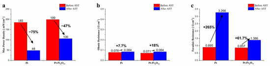
Figure 6.
Summary of experiments. (a) Performance of fuel cells, (b) ohmic resistances of fuel cells, (c) Faradaic resistances of fuel cells.
Regarding ohmic resistance, the difference between before and after the AST cycle for both cases is negligible, indicating that the ohmic resistance parameter remained relatively stable. However, for faradaic resistance, the Pt-Pr6O11 cell shows a 4.3% lower resistance than the reference before AST and a significantly lower resistance (57.6%) after AST.
These results confirm that Pr6O11 effectively stabilizes Pt in the co-sputtered Pt-Pr6O11 cermet electrode, particularly under harsh conditions. Pt-Pr6O11 shows minimized performance degradation and maintains higher electrochemical stability compared to the reference cells.
4. Conclusions
In this study, a cermet electrode combining praseodymium-based oxide (Pr6O11) with platinum was used to enhance the performance and durability of a polymer electrolyte membrane fuel cell. The electrode was fabricated using a thin film method via co-sputtering, resulting in a film thickness of approximately 120 nm on an Si wafer. It was applied to the PEMFC without the need for an additional ionomer coating process. The electrochemical performance of the fuel cell was evaluated at an operating temperature of 70 °C, with fully humidified hydrogen supplied at 100 sccm and air at 200 sccm, respectively.
The initial performance showed that the Pr6O11 case achieved a maximum power density of 199 mW/cm2, a 7.6% improvement compared to the 185 mW/cm2 of the reference case. After undergoing 10,000 cycles of AST, the Pr6O11 cell maintained a performance of 106 mW/cm2, which was 121% higher than the 48 mW/cm2 achieved by the reference cell. In terms of degradation rate, the Pr6O11 case exhibited a 47% degradation, significantly better than the 75% degradation observed in the reference case.
This study demonstrated that incorporating Pr6O11 into the Pt particles through co-sputtering resulted in strong interaction between Pt and Pr6O11, enhancing the oxygen reduction reaction of Pt and improving catalyst durability. These findings provide meaningful insights for researchers aiming to enhance the performance and stability of PEMFCs.
Author Contributions
Methodology, Y.R.K. and B.K.K.; Formal analysis, D.Y.J.; Resources, S.K.K.; Writing—original draft, K.W.H.; Writing—review & editing, D.K.S. and S.R.; Supervision, G.Y.C. All authors have read and agreed to the published version of the manuscript.
Funding
This research was supported by a Korea Institute for Advancement of Technology (KIAT) grant funded by the Korean Government (Ministry of Education-Ministry of Trade, Industry and Energy) (P0022075, Future Automobile Technology Convergence Innovation Talent Training Program in 2024). This research was supported by a grant (H2409002) from Gyeonggi technology Development Program funded by Gyeonggi Province. This work was partially supported by a Korea Institute of Energy Technology Evaluation and Planning (KETEP) grant funded by the Korean government (MOTIE) (20213030030260, Development of Lightweight Fuel Cell System for Air Mobility). This work was also partially supported by the National Research Foundation of Korea (NRF) grant funded by the Korean government (MSIT). (No. RS-2023-00213741). This work was supported by the Technology Innovation Program (20025646, Industry & Energy (MOTIE, Korea).
Data Availability Statement
The data presented in this study are available on request from the corresponding author.
Conflicts of Interest
The authors declare no conflicts of interest.
References
- O’Hayre, R.; Cha, S.-W.; Colella, W.; Prinz, F.B. Fuel Cell Fundamentals; WILEY: Hoboken, NJ, USA, 2016. [Google Scholar]
- Hong, S.; Lim, Y.; Lee, H.; Chung, W.; Hwang, H.; Kim, H.; Kim, Y.-B. Rapid Surface Kinetics Enhancement via Flash Light Sintering for Low-Temperature Solid Oxide Fuel Cells. J. Alloys Compd. 2019, 778, 337–344. [Google Scholar] [CrossRef]
- Bühre, L.V.; McLeod, A.J.; Trinke, P.; Bensmann, B.; Benecke, M.; Herrera, O.E.; Mérida, W.; Hanke-Rauschenbach, R. Adaptation of a PEMFC Reference Electrode to PEMWE: Possibilities and Limitations. J. Electrochem. Soc. 2023, 170, 094507. [Google Scholar] [CrossRef]
- Li, H.-Y.; Kamlungsua, K.; Ng, K.; Shin, J.-Y.; Su, P.-C. On the Composition of Sr2Fe1.5Mo0.5O6-δ—Sm0.2Ce0.8O2-δ Composite as Fuel Electrodes for Hydrogen Reversible Solid Oxide Cells. Fuel 2023, 348, 128642. [Google Scholar] [CrossRef]
- Kregar, A.; Kravos, A.; Katrašnik, T. Methodology for Evaluation of Contributions of Ostwald Ripening and Particle Agglomeration to Growth of Catalyst Particles in PEM Fuel Cells. Fuel Cells 2020, 20, 487–498. [Google Scholar] [CrossRef]
- Park, H.W.; Seo, B.G.; Shim, J.W.; Kim, N.I.; Choi, Y.S.; Shim, J.H. Atomic Layer Deposited Platinum on Tungsten Oxide Support as High Performance Hybrid Catalysts for Polymer Electrolyte Membrane Fuel Cells. Appl. Catal. B Environ. 2023, 337, 122956. [Google Scholar] [CrossRef]
- Von Kraemer, S.; Wikander, K.; Lindbergh, G.; Lundblad, A.; Palmqvist, A.E.C. Evaluation of TiO2 as Catalyst Support in Pt-TiO2/C Composite Cathodes for the Proton Exchange Membrane Fuel Cell. J. Power Sources 2008, 180, 185–190. [Google Scholar] [CrossRef]
- Zhao, J.; Tu, Z.; Chan, S.H. Carbon Corrosion Mechanism and Mitigation Strategies in a Proton Exchange Membrane Fuel Cell (PEMFC): A Review. J. Power Sources 2021, 488, 229434. [Google Scholar] [CrossRef]
- Wang, J.; Yin, G.; Shao, Y.; Zhang, S.; Wang, Z.; Gao, Y. Effect of Carbon Black Support Corrosion on the Durability of Pt/C Catalyst. J. Power Sources 2007, 171, 331–339. [Google Scholar] [CrossRef]
- Kolluru, S.; Jain, G.M.; Gollapudi, D.; Reddy, L.E.; Ramesh, G.V. Recent Developments in Pt-Based Alloy Nanoparticles for Oxygen Reduction Reaction in Fuel Cells. Mater. Today Proc. 2023, 92, 764–770. [Google Scholar] [CrossRef]
- Lee, K.H.; Kwon, K.; Roev, V.; Yoo, D.Y.; Chang, H.; Seung, D. Synthesis and Characterization of Nanostructured PtCo-CeOx/C for Oxygen Reduction Reaction. J. Power Sources 2008, 185, 871–875. [Google Scholar] [CrossRef]
- Liu, G.; Yang, Z.; Wang, X.; Fang, B. Ordered Porous TiO2@C Layer as an Electrocatalyst Support for Improved Stability in PEMFCs. Nanomaterials 2021, 11, 3462. [Google Scholar] [CrossRef] [PubMed]
- Shen, G.; Liu, J.; Wu, H.B.; Xu, P.; Liu, F.; Tongsh, C.; Jiao, K.; Li, J.; Liu, M.; Cai, M.; et al. Multi-Functional Anodes Boost the Transient Power and Durability of Proton Exchange Membrane Fuel Cells. Nat. Commun. 2020, 11, 1191. [Google Scholar] [CrossRef]
- Fiala, R.; Vaclavu, M.; Rednyk, A.; Khalakhan, I.; Vorokhta, M.; Lavkova, J.; Potin, V.; Matolinova, I.; Matolin, V. Pt–CeOx Thin Film Catalysts for PEMFC. Catal. Today 2015, 240, 236–241. [Google Scholar] [CrossRef]
- Seo, B.G.; Koo, J.; Jeong, H.J.; Park, H.W.; Kim, N.I.; Shim, J.H. Performance Enhancement of Polymer Electrolyte Membrane Fuel Cells with Cerium Oxide Interlayers Prepared by Aerosol-Assisted Chemical Vapor Deposition. ACS Sustain. Chem. Eng. 2023, 11, 10776–10784. [Google Scholar] [CrossRef]
- Li, G.; Zheng, W.; Li, X.; Luo, S.; Xing, D.; Ming, P.; Li, B.; Zhang, C. Application of the Ce-Based Radical Scavengers in Proton Exchange Membrane Fuel Cells. Int. J. Hydrogen Energy 2024, 74, 17–30. [Google Scholar] [CrossRef]
- Zhu, W.; Pei, Y.; Liu, H.; Yue, R.; Ling, S.; Zhang, J.; Liu, X.; Yin, Y.; Guiver, M.D. Space Confinement to Regulate Ultrafine CoPt Nanoalloy for Reliable Oxygen Reduction Reaction Catalyst in PEMFC. Adv. Sci. 2023, 10, 2206062. [Google Scholar] [CrossRef]
- Duan, H.; Xu, C. Nanoporous PtPd Alloy Electrocatalysts with High Activity and Stability toward Oxygen Reduction Reaction. Electrochimica Acta 2015, 152, 417–424. [Google Scholar] [CrossRef]
- Zhan, C.; Sun, H.; Lü, L.; Bu, L.; Li, L.; Liu, Y.; Yang, T.; Liu, W.; Huang, X. Zinc Intercalated Lattice Expansion of Ultrafine Platinum–Nickel Oxygen Reduction Catalyst for PEMFC. Adv. Funct. Mater. 2023, 33, 2212442. [Google Scholar] [CrossRef]
- Dull, S.M.; Vinogradova, O.; Xu, S.; Koshy, D.M.; Vullum, P.E.; Torgersen, J.; Kirsch, S.; Viswanathan, V.; Jaramillo, T.F.; Prinz, F.B. Alloyed Pt–Zn Oxygen Reduction Catalysts for Proton Exchange Membrane Fuel Cells. ACS Appl. Energy Mater. 2022, 5, 8282–8291. [Google Scholar] [CrossRef]
- Wu, Y.; Wang, S.; Zhang, M.; Hong, Y.; Zhang, X.; Wang, C.; He, W.; Zhou, G.; Chen, Y.; Zhang, Y. Enhanced Activity of Oxygen Reduction Reaction on Pr6O11-Assisted PtPr Alloy Electrocatalysts. ACS Appl. Mater. Interfaces 2022, 14, 41861–41869. [Google Scholar] [CrossRef] [PubMed]
- He, Q.; Mukerjee, S.; Parres-Esclapez, S.; Bueno-López, A. Effect of Praseodymium Oxide and Cerium–Praseodymium Mixed Oxide in the Pt Electrocatalyst Performance for the Oxygen Reduction Reaction in PAFCs. J. Appl. Electrochem. 2011, 41, 891–899. [Google Scholar] [CrossRef]
- Guerini, S.; Piquini, P. First-Principles Study of the (112¯0)HBN/(112¯)CBN Interface. Phys. Rev. B 2005, 71, 193305. [Google Scholar] [CrossRef]
- He, H.; Dai, H.X.; Au, C.T. Defective Structure, Oxygen Mobility, Oxygen Storage Capacity, and Redox Properties of RE-Based (RE = Ce, Pr) Solid Solutions. Catal. Today 2004, 90, 245–254. [Google Scholar] [CrossRef]
- Ostroverkh, A.; Johánek, V.; Dubau, M.; Kúš, P.; Khalakhan, I.; Šmíd, B.; Fiala, R.; Václavů, M.; Ostroverkh, Y.; Matolín, V. Optimization of Ionomer-Free Ultra-Low Loading Pt Catalyst for Anode/Cathode of PEMFC via Magnetron Sputtering. Int. J. Hydrogen Energy 2019, 44, 19344–19356. [Google Scholar] [CrossRef]
- Li, Y.; Tian, Y.; Li, Z.; Wu, X.; Wang, L.; Bian, T. Boosting the Performance of La0.5Sr0.5Fe0.9Mo0.1O3-δ Oxygen Electrode via Surface-Decoration with Pr6O11 Nano-Catalysts. Int. J. Hydrogen Energy 2024, 84, 305–312. [Google Scholar] [CrossRef]
- Ando, F.; Gunji, T.; Tanabe, T.; Fukano, I.; Abruña, H.D.; Wu, J.; Ohsaka, T.; Matsumoto, F. Enhancement of the Oxygen Reduction Reaction Activity of Pt by Tuning Its D-Band Center via Transition Metal Oxide Support Interactions. ACS Catal. 2021, 11, 9317–9332. [Google Scholar] [CrossRef]
- Chen, M.; Rao, P.; Miao, Z.; Luo, J.; Li, J.; Deng, P.; Huang, W.; Tian, X. Strong Metal-Support Interaction of Pt-Based Electrocatalysts with Transition Metal Oxides/Nitrides/Carbides for Oxygen Reduction Reaction. Microstructures 2023, 3, 2023025. [Google Scholar] [CrossRef]
- Zhang, L.; Li, T.; Du, T.; Dai, X.; Zhang, L.; Tao, C.; Ding, J.; Yan, C.; Qian, T. Manipulation of Electronic States of Pt Sites via D-Band Center Tuning for Enhanced Oxygen Reduction Reaction in Proton Exchange Membrane Fuel Cells. Inorg. Chem. 2024, 63, 2138–2147. [Google Scholar] [CrossRef]
- Ruban, A.; Hammer, B.; Stoltze, P.; Skriver, H.L.; Nørskov, J.K. Surface Electronic Structure and Reactivity of Transition and Noble Metals. J. Mol. Catal. A Chem. 1997, 115, 421–429. [Google Scholar] [CrossRef]
- Hong, J.; Kim, S.; Kim, J. First-Principles Study on the d-Band Center of Pt Alloyed with 3d Transition Metals. J. Korean Phys. Soc. 2023, 83, 964–969. [Google Scholar] [CrossRef]
- Zhang, X.; Li, H.; Yang, J.; Lei, Y.; Wang, C.; Wang, J.; Tang, Y.; Mao, Z. Recent Advances in Pt-Based Electrocatalysts for PEMFCs. RSC Adv. 2021, 11, 13316–13328. [Google Scholar] [CrossRef] [PubMed]
- Huang, Y.; Long, B.; Tang, M.; Rui, Z.; Balogun, M.-S.; Tong, Y.; Ji, H. Bifunctional Catalytic Material: An Ultrastable and High-Performance Surface Defect CeO2 Nanosheets for Formaldehyde Thermal Oxidation and Photocatalytic Oxidation. Appl. Catal. B Environ. 2016, 181, 779–787. [Google Scholar] [CrossRef]
- Li, Z.; Zhou, P.; Zhao, Y.; Jiang, W.; Zhao, B.; Chen, X.; Li, M. Ultradurable Pt-Based Catalysts for Oxygen Reduction Electrocatalysis. Catalysts 2024, 14, 57. [Google Scholar] [CrossRef]
- Shao-Horn, Y.; Ferreira, P.; la O’, G.J. Instability of Pt/C Electrocatalysts in Proton Exchange Membrane Fuel Cells: A Mechanistic Investigation. Electrochem. Soc. Meet. Abstr. 2006, MA2005-03, 200. [Google Scholar] [CrossRef]
- Meier, J.C.; Galeano, C.; Katsounaros, I.; Witte, J.; Bongard, H.J.; Topalov, A.A.; Baldizzone, C.; Mezzavilla, S.; Schüth, F.; Mayrhofer, K.J.J. Design Criteria for Stable Pt/C Fuel Cell Catalysts. Beilstein J. Nanotechnol. 2014, 5, 44–67. [Google Scholar] [CrossRef] [PubMed]
- Prass, S.; St-Pierre, J.; Klingele, M.; Friedrich, K.A.; Zamel, N. Hydrogen Oxidation Artifact During Platinum Oxide Reduction in Cyclic Voltammetry Analysis of Low-Loaded PEMFC Electrodes. Electrocatalysis 2021, 12, 45–55. [Google Scholar] [CrossRef]
- Fiala, R.; Vaclavu, M.; Vorokhta, M.; Khalakhan, I.; Lavkova, J.; Potin, V.; Matolinova, I.; Matolin, V. Proton Exchange Membrane Fuel Cell Made of Magnetron Sputtered Pt–CeOx and Pt–Co Thin Film Catalysts. J. Power Sources 2015, 273, 105–109. [Google Scholar] [CrossRef]
Disclaimer/Publisher’s Note: The statements, opinions and data contained in all publications are solely those of the individual author(s) and contributor(s) and not of MDPI and/or the editor(s). MDPI and/or the editor(s) disclaim responsibility for any injury to people or property resulting from any ideas, methods, instructions or products referred to in the content. |
© 2024 by the authors. Licensee MDPI, Basel, Switzerland. This article is an open access article distributed under the terms and conditions of the Creative Commons Attribution (CC BY) license (https://creativecommons.org/licenses/by/4.0/).