Article

Distributed Real-Time Feedback Optimization for Renewable Energy Sources and Vehicle-to-Grid Power Compensation of Electric Vehicle Chargers in Distribution Systems

Department of Electrical and Electronic Engineering, The University of Hong Kong, Hong Kong, China
*
Author to whom correspondence should be addressed.
Sustainability 2024, 16(6), 2432; https://doi.org/10.3390/su16062432
Submission received: 30 November 2023 / Revised: 28 February 2024 / Accepted: 8 March 2024 / Published: 14 March 2024

Abstract

:
A novel distributed feedback optimization-based controller for electric vehicle (EV) chargers and renewable energy sources (RESs) in distribution systems is proposed. The proposed controller utilizes the flexibility in EV chargers’ active and reactive power consumption to offer the desirable vehicle-to-grid services. Instead of using the conventional cascaded PI controllers, a new optimization-based approach is proposed to control RESs to track their power injection setpoints. The proposed controller formulates the control targets as a single constrained optimization problem, i.e., to minimize the critical bus voltage magnitude deviations while driving RESs to follow their power setpoints, thereby fulfilling the EV charging requirements and regulating their power outputs and bus voltage magnitudes to stay within their limits. A distributed feedback optimization-based control algorithm is designed for EV chargers and RESs to steer the system trajectories of the distribution systems towards the optimal solution of the formulated optimization problem. Simulation results show that the proposed controller can always steer the test system to the optimal solution of the optimization problem. The advantages of the real-time vehicle-to-grid power compensation of EV chargers are also demonstrated.

1. Introduction

With the growing concern of global warming and climate change, renewable energy sources (RESs) and electric vehicles (EVs) are gaining more attention recently. RESs are considered more environmentally friendly than conventional fossil fuel-based generation, and they are being progressively installed in distribution systems with financial incentives from governments [1,2,3]. Alongside the promotion of RESs, EV adoption is encouraged worldwide, as EVs are more ecofriendly than conventional fossil fuel-based vehicles. Fewer air pollutants and greenhouse gases are emitted from EVs [4,5,6,7]. Despite the aforementioned appealing advantages, the proliferation of RESs and EVs introduces unprecedented challenges to distribution systems.
RESs give rise to the fast fluctuations of bus voltage magnitudes in distribution systems. The active power outputs of RESs depend on the weather conditions. For example, the active power outputs of PV panels depend on solar irradiance, and that of wind turbines depend on wind speed. Their active power outputs are thus intermittent and volatile. Due to the high R/X ratio of distribution lines, the bus voltage magnitudes in distribution systems are sensitive to the active power fluctuations from RESs, i.e., they fluctuate as the active power outputs from RESs fluctuate. However, conventional voltage regulation devices, such as capacitor banks and load tap changers, cannot handle the fast fluctuating bus voltage magnitudes, as they cannot be switched frequently [8]. New control strategies and devices are needed to handle the issue of bus voltage magnitude regulation.
The charging requirement of EVs burdens distribution systems. With the advancement in fast charging technology, high-rating EV chargers are being increasingly installed in distribution systems, such as the 43 kW charger in [9] and the 135 kW Tesla Supercharger in [10]. Although these high-rating EV chargers can rapidly charge EVs, they will introduce negative impacts such as transformer overloading and voltage instability in distributed systems if not appropriately coordinated [11]. Hence, research into optimal EV charging scheduling has been done to optimally charge EVs or even control EVs to provide vehicle-to-grid (V2G) services [12,13,14,15,16,17,18,19,20,21]. Nevertheless, research into optimal EV charging scheduling usually focuses on optimizing the EV charging rate over a long time window, e.g., 1 h or 30 min. The potential of EV chargers in offering real-time grid ancillary services, e.g., regulating the fast fluctuating bus voltage magnitudes, should be addressed.
Feedback optimization (FO) is an emerging optimization technique in power system engineering and other engineering areas. It aims to drive the equilibrium point of the system to the solution of a prescribed optimization problem [22,23,24,25,26,27,28,29,30,31]. Rather than simulating the system, it measures the output from the real system and updates the optimal control input based on the sensitivity between the input and the output. As a result, it is robust to model mismatch and has a low computational burden. FO has been applied in robotics control [32,33], transmission and distribution systems [25,26,27,28,29,30,31], and microgrid control [34,35,36].
A distributed real-time FO-based control method for EV chargers and RESs is proposed in this paper to regulate the bus voltage magnitudes in distribution systems. The proposed controller aims to minimize the critical bus (CB) voltage magnitude deviations while driving RESs to follow their power injection setpoints, thereby fulfilling EV charging requirements and regulating EV power outputs and bus voltage magnitudes to stay within their limits. A time-varying constrained optimization problem is formulated to achieve the above aims. A distributed Karush–Kuhn–Tucker dynamic-based FO algorithm is designed to control EV chargers and RESs to drive the system trajectories of distribution systems to the optimal solution of the formulated optimization problem. The distributed nature of the proposed algorithm eliminates the need for a central controller and, thus, is robust to single-point failure. Simulation results show that the proposed FO-based controller can tightly drive the distribution system to follow the optimal operating point defined by the optimization problem.
The novelties of the proposed controller are the following:
  • It unleashes the real-time grid support capability of EV chargers. The current literature usually optimizes the charging schedule of EV charges over a long time window. The flexibility in battery charging to offer real-time bus voltage magnitude regulation service is neglected. On the other hand, the proposed controller optimizes the control signals to EV chargers in real time to regulate the CB voltage magnitudes, which are vulnerable to time-varying fluctuating power outputs from RESs.
  • It avoids the potential control conflicts between RESs and other controllable devices by formulating their control targets in a single optimization problem. RESs are generally controlled as grid-following inverters to follow their power injection setpoints with cascaded PI controllers. This control strategy does not consider other control targets in the distribution system and lacks coordination with other controllable devices. On the other hand, in the proposed optimization-based controller, their power setpoint tracking requirements are formulated alongside other control targets, i.e., CB voltage magnitude regulation, in a single optimization problem. EV chargers and RESs are controlled synergistically to achieve their control targets.
The paper is structured as follows. Section 2 gives an overview of the existing literature on the optimization of EV charging. Section 3 discusses the model of the distribution system. Section 4 introduces the formulation of the optimization problem. The proposed FO-based controller is explained in Section 5, followed by the case studies in Section 6. The conclusions are given in Section 7.

2. Literature Review

This section briefly overviews the research into optimal EV charging scheduling. Readers may refer to the reviews in [5,9,11,17,37,38,39,40] for more details.
V2G technology can be classified into unidirectional V2G technology and bidirectional V2G technology. In unidirectional V2G technology, EVs are charged at different rates to offer grid ancillary services, and the energy in the batteries does not flow into the power grid. In bidirectional V2G technology, the EVs are charged and discharged at different rates, and energy in the batteries can flow into the power grid. Research into the optimal scheduling of EV chargers has been done in both types of V2G technology.
Various V2G optimization targets have been considered in the literature. In [41], the operation costs in parking lots with PV systems were considered, and the optimal charging rates were computed in 30 min intervals. The work of [42] proposed a particle swarm optimization-based algorithm to optimally schedule the EV charging process hourly to reduce energy losses and improve the voltage profiles in the distribution system. A mixed-integer programming optimization problem was formulated in [43] to optimize the EV hourly charging schedule to minimize the operating cost of the power system. Complex, large-scale optimization problems are usually formulated in the literature with forecasts of variables, such as EV arrival time load profiles, to compute the optimal EV charging schedule over a long time window, e.g., 30 min or 1 h. The computational burden of solving these complex optimization problems is high, and the solved EV optimal charging schedule may not be updated quickly enough to deal with the fast fluctuations caused by RESs. In addition, the optimization problems usually focus on the active power flow between EV batteries and the power grid. The reactive power support capability of EV chargers is often neglected. In fact, their reactive power support capability can be utilized to offer grid ancillary services [18,19,20,21,44].
FO is used in the proposed controller to drive the distribution system to the optimal solution of the formulated optimization problem, which will be discussed in detail in Section 4. It will be shown in Section 5 that the computational burden of the proposed FO-based algorithm is low, i.e., only simple multiplications of matrices and vectors are required to compute the control signals at each time step. Control signals can thus be provided to the EV chargers in a faster time scale to regulate the bus voltage magnitudes against the disturbance from RESs. Moreover, both the active power support from EV batteries and the EV chargers’ reactive power support capability are exploited to offer grid ancillary services.

3. Model Description

A distribution system with n E V EV chargers, n R E S RESs, n L i n e distribution lines, n b u s buses, and n l o a d loads is considered. Their index sets are denoted as N E V , N R E S , N l i n e , N b u s , and N l o a d . The notation x X denotes a concatenated vector consisting of x i , i X . For instance, assume X = { 1 , 3 } ; then, x X = [ x 1 T , x 3 T ] T .
The distribution system is assumed to be three-phase balanced. The three-phase balanced signals are transformed into direct and quadrature ( d q ) axes components with the power-invariant Park transformation. The variables modeled in the d q coordinate are bolded in the following context. The state equations in the distribution system are represented on the reference frame rotating at the utility grid frequency ω c . The magnitude of variables in the d q axis coordinate is defined as follows:
x = x d 2 + x q 2
where x d and x q are the d axis component and q axis component of x , respectively.
Note that the phase lock loop dynamics of the EV chargers and RESs are neglected in this paper, and they are assumed to track the utility grid frequency ω c tightly. Thus, their state equations are modeled using the frequency ω c .

3.1. Electric Vehicle Charger Model

Figure 1 shows the configuration of the EV charger. EV chargers are assumed to be constructed with bidirectional inverters and their output connectors. Note that the DC-side dynamics are neglected for simplicity. The dynamics of the EV charger i , i N E V connected to bus j , j N b u s are modeled as follows:
i ˙ s i = L f i 1 ( R f i i s i + v s i v o i ) + ω c K i s i
v ˙ o i = C f i 1 ( i s i i o i ) + ω c K v o i
i ˙ o i = L c i 1 ( R c i i o i + v o i v bus j ) + ω c K i o i ,
where K = 0 1 1 0 ; R f i , L f i , and C f i denote the output filter’s resistance, inductance, and capacitance, respectively; R c i and L c i denote the output connector resistance and inductance, respectively; v bus j , v o i , and v s i denote the bus voltage, the output voltage, and the switching voltage, respectively. The switching voltage, v s i , is the control input to the EV charger, and it is controlled by the proposed FO-based controller.
The active power output, P i , and the reactive power output, Q i , of the EV charger i are defined as follows:
P i = v o d i i o d i + v o q i i o q i , Q i = v o q i i o d i v o d i i o q i .
When P i is positive, the EV charger i provides V2G service to supply the energy stored in the EV battery to the distribution system. When P i is negative, the EV charger charges the EV battery.

3.2. Renewable Energy Source Model

The RES configuration is shown in Figure 2. The RES model is similar to the EV charger model, except that the bidirectional inverter is replaced with a unidirectional inverter. Here, the inverter model in [45] is adopted. Like the EV charger model, the DC-side dynamics are neglected. The state equations of the RES i, i N R E S connected to bus j , j N b u s are as follows:
i ˙ s i = L f i 1 ( R f i i s i + v s i v o i ) + ω c K i s i
v ˙ o i = C f i 1 ( i s i i o i ) + ω c K v o i
i ˙ o i = L c i 1 ( R c i i o i + v o i v bus j ) + ω c K i o i .
v s i is the control input to the RES i, and it is controlled by the proposed FO-based controller. Note that the power outputs of the RESs are defined in the same way as the EV power outputs in Equation (5).

3.3. Distribution Line Model

The RLC distribution line model in [46] is adopted, i.e., the distribution line i, i N l i n e is modeled with series resistance R l i n e i and inductance L l i n e i . Moreover, the distribution line is assumed to induce a shunt capacitance C l i n e i between the bus and the ground. The dynamics of the bus voltage will be introduced in the bus model section. Here, the dynamics of the line current i line i between bus j and k, j , k N b u s are as follows:
i ˙ line i = L l i n e i 1 ( R l i n e i i line i + v bus j v bus k ) + ω c K i line i .

3.4. Load Model

The loads are modeled as RL loads. The dynamics of the load current i ˙ load i , i N l o a d at bus j , j N b u s are as follows:
i ˙ load i = L l o a d i 1 ( R l o a d i i load i + v bus j ) + ω c K i load i
where R l o a d i and L l o a d i are the resistance and inductance, respectively.

3.5. Bus Model

The bus voltage, v b u s i , i N b u s , is assumed to be dynamic, and there exists a shunt capacitor between the bus and the ground. The voltage dynamics are as follows:
v ˙ bus i = C s h u n t i 1 i in i + ω c K v bus i
where C s h u n t i denotes the shunt capacitance; i in i is the current flowing into the shunt capacitor. When no capacitor banks are connected to bus i, C s h u n t i is defined as the shunt capacitance induced by the distribution lines. Otherwise, C s h u n t i is defined as the capacitance of the capacitor bank for simplicity, since the capacitance of the capacitor bank is much larger than that induced by the distribution lines.

3.6. Interconnected System Model

The model discussed above forms an interconnected system as follows:
x ˙ = f ( x , u )
y = h ( x , u )
where x = [ i s N EV T , v o N EV T , i o N EV T , i s N RES T , v o N RES T , i o N RES T , i line N line T , i load N load T , v bus N bus T T ] T is the state variable; u = [ v s N EV T , v s N RES T ] is the control variable to be controlled by the proposed FO-based controller; and y = [ P N E V T , Q N E V T , S N E V T , P N R E S T , Q N R E S T , V bus N bus T ] T is the output variable, where S is the apparent power defined as S = P 2 + Q 2 .

4. Optimization Problem Formulation

The proposed FO-based controller aims to drive the steady state of the interconnected system in (12) to the solution of a predefined optimization problem. This paper considers CB voltage magnitude regulation and formulates it as the objective function. Other control targets, such as power loss minimization, can also be included in the objective function, but they are not considered in this paper for simplicity.
Apart from regulating the CB voltage magnitudes, the proposed controller also steers the active power output of the RESs to their MPPT profiles and their reactive power output to zero. The power tracking requirement of the RESs is formulated as equality constraints in the optimization problem.
While controlling EV chargers to offer grid ancillary service, their active power output limits, reactive power output limits, apparent power output limits, and the bus voltage magnitude limits must be satisfied. These limits are formulated as inequality constraints in the optimization problem.
The following optimization problem is formulated accordingly:
min u i N C B ζ i 2 ( V bus i V n o m ) 2 CB Voltage Magnitude Deviation
subject to f ( x , u ) = 0 n x
y = h ( x , u )
P N R E S = P M P P T N R E S ( t )
Q N R E S = 0 n R E S
v ̲ b u s i v bus i v ¯ b u s i , i N b u s
P ̲ i ( t ) P i P ¯ i ( t ) , i N E V
Q ̲ i Q i Q ¯ i , i N E V
S i S ¯ i , i N E V
where N C B is the index set of the CB; V n o m is the standard voltage magnitude; ζ i is the weighting of the CB i voltage magnitude deviation; 0 n x denotes an n x -dimensional zero vector; n x is the dimension of x; equality constraints (13d) and (13e) ensure the RESs are tracking their power setpoints; P M P P T N R E S denotes the RESs’ MPPT profiles; and inequality constraints (13f) to (13i) denote the power limits of EV chargers and the bus voltage magnitudes.
The optimization problem (13) is rewritten in the following compact form to simplify the subsequent discussion:
min u Φ ( y )
subject to f ( x , u ) = 0 n x
y = h ( x , u )
A e q y = b e q ( t )
A l e q y b l e q ( t )
where A e q and A l e q are constant matrices; and b e q ( t ) and b l e q ( t ) are time-varying vectors.
This paper focuses on regulating CB voltage magnitudes. Nevertheless, the optimization-based structure of the proposed controller allows for easy extension to other EV charging control targets. The following are some of the possible extensions:
  • Interface with Preset Optimal EV Active Power Charging Schedule: The proposed controller can interface with the preset EV active power consumption schedules by setting the P ̲ ( t ) and P ¯ ( t ) in (13) to the scheduled active power consumption, i.e., driving the active power consumption of the EVs to follow the preset active charging profiles computed by other optimization algorithms. In this case, the proposed controller still optimizes the EV chargers’ reactive power consumption to offer real-time grid ancillary service to the distribution systems.
  • Battery Degradation Consideration: V2G technology inevitably accelerates the degradation of EV batteries. Their charging and discharging rates need to be carefully controlled to relieve their aging problem. The proposed controller can slow down the aging problem by setting the P ̲ ( t ) and P ¯ ( t ) as functions of their state of charge. For example, when the state of charge of EV i is low, then P ¯ i ( t ) can be set to zero, i.e., it stops drawing energy from them to avoid damaging the battery.

5. Proposed Feedback Optimization-Based Controller

FO uses the system output measurements to drive the equilibrium point of the system to the solution of a predefined optimization problem. It has been applied in various areas such as robotics control [32,33], transmission and distribution systems [25,26,27,28,29,30,31] and microgrid control [34,35,36]. This paper applies FO in the distribution system to optimally control EV chargers and RESs.
Assuming that the steady state mapping from input u to output y is denoted as y = g ( u ) , the augmented Lagrangian of the optimization problem (14) is formulated as follows:
L ( u , λ , μ ) = Φ ( g ( u ) ) + λ T ( A e q g ( u ) b e q ( t ) ) + σ 2 A e q g ( u ) b e q ( t ) 2 + μ T ( A l e q g ( u ) b l e q ( t ) )
where σ is the argumentation parameter.
Based on the augmented Lagrangian (15), the following Karush–Kuhn–Tucker-based discrete time FO controller is designed:
u [ k ] = u [ k 1 ] ϵ u ( H 0 T ( Φ ( y ) | y [ k 1 ] + A e q T λ [ k 1 ] + ρ A e q T ( A e q y [ k 1 ] b e q [ k 1 ] ) Ψ ( y , λ , μ )
+ A l e q T μ [ k 1 ] ) Ψ ( y , λ , μ ) )
λ [ k ] = λ [ k 1 ] + ϵ λ ( A e q y [ k 1 ] b e q [ k 1 ] )
μ i [ k ] = 0 { μ i [ k 1 ] + ϵ μ ( row i ( A l e q ) y b l e q i [ k 1 ] ) } for i = 1 , , n l e q ,
where ϵ u , ϵ λ , and ϵ μ are the gain size in the controller; λ and μ are the Lagrange multipliers; H 0 is the input-to-output sensitivity matrix whose derivation will be explained later; n l e q denotes the number of inequality constraints; μ i is assumed to be initialized at 0; Φ ( y ) denotes the gradient of Φ ( y ) with respect to y; 0 { · } denotes the projection operator, i.e., 0 { a } = max { a , 0 } ; and row i ( A ) denotes the i th row of the matrix A.
To derive H 0 in (16), the procedures in [36] are used. Particularly, (12) are first linearized as follows:
Δ x ˙ = A Δ x + B Δ u
Δ y = C Δ x + D Δ u
where A, B, C, and D are the corresponding Jacobian matrices. Then, Δ x ˙ in (17a) is set to zero, thereby resulting in Δ x = A 1 B Δ u . Substituting Δ x into (17b), Δ y equals to ( D A 1 B + E ) Δ u , where D A 1 B + E is the function of the estimated sensitivity matrix H.
To implement the algorithm (16) in a distributed way, the h i j entry in the i th row and j th column in H is set to zero if the device corresponding to u j cannot obtain the information to compute the i th entry in Ψ ( y , λ , μ ) . For instance, assume the first entry of Ψ ( y , λ , μ ) to be y 1 , λ 1 and its second entry to be y 2 , μ 2 ; if the device corresponding to u 1 can only obtain the information of y 2 , μ 2 , then h 21 remains unchanged in H, but h 11 is set to zero.
Eventually, H is evaluated at the distribution system’s arbitrarily chosen steady state operating point as H 0 . H 0 is then distributed to the EV chargers and RESs to implement the control algorithm (16) in a distributed way. One way to choose the steady state operating point is to solve the optimization problem (13) and use the solution to substitute into H to obtain H 0 .

6. Case Studies

A modified four-bus distribution test system in [47] was used. Its configuration is shown in Figure 3. The standard voltage magnitude V n o m was set to 400 V, with the bus voltage magnitude limits set to 360 V to 440 V for all buses. The voltage magnitude at the point of common coupling was assumed to be 400 V, with the d axis component being 400 V and the q axis component being 0 V. For simplicity, the frequency of the utility grid was assumed to be fixed at 50 Hz. Bus 3 was selected as the CB. Four identical capacitor banks with capacitance C s h u n t = 6 × 10 4 F were installed in four buses. The MPPT profiles of R E S 1 and R E S 2 are plotted in Figure 4.
H 0 was calculated using the procedures discussed in the previous section. The optimization problem (13) was solved by setting the P M P P T R E S as the initial value of the RESs’ MPPT profiles, and the solution was substituted into H to obtain H 0 .
The capacities of the two EV batteries were assumed to be 60 kWh, with the initial state of energy storage being 10 kWh and 40 kWh for E V 1 and E V 2 , respectively. The apparent power limits of the EV chargers were set to be 20,000 VA. The upper and lower limits of the reactive power output of the EV chargers were set to 6000 Var and −6000 Var, respectively. Given that the state of charge of E V 1 is low, the upper limit of the active power injection of E V 1 was set to zero to avoid withdrawing energy from it. Meanwhile, its active power injection lower limit was set to −20,000 W to allow as much active power to charge it as possible. For E V 2 , the upper and lower active power injection limits were set to be 20,000 W and −20,000 W, respectively.
Four case studies were carried out to demonstrate the control performance of the proposed controller, which are described as follows:
  • The proposed controller was applied to the dynamic system model in Section 3. The communication time interval between each device was set to 0.1 s, i.e., the control input to EVs and RESs were updated every 0.1 s. The RLC dynamics of the distribution system were simulated.
  • Optimization problem (13) was solved every second, with P M P P T N R E S ( t ) in (13d) being set to the corresponding MPPT profiles. This case study is a benchmark to test whether the proposed controller can drive the distribution system to the optimal steady state condition defined in (13) at each second. Note that this case study does not consider the dynamics of the system. The results are the steady state optimal condition of the distribution system with the corresponding RESs’ power injection setpoints in each second.
  • Algebraic Equations (13b) to (13e) were solved every second, with P M P P T N R E S ( t ) in (13d) being set to the corresponding MPPT profiles and the active and reactive power injections of the EVs being set to their average values in case study 2. This case study demonstrates the existing approach in optimizing the EV charging schedule, i.e., the power injection commands to the EV chargers are fixed within each time window, which was assumed to be 1 h in this case study. Note that this case study does not consider the dynamics of the system. The results are the steady state condition of the distribution system with the corresponding EV chargers’ power injections and the RESs’ power injection setpoints in each second.
  • Algebraic Equations (13b) to (13e) were solved every second, with P M P P T N R E S ( t ) in (13d) being set to the corresponding MPPT profiles and the active and reactive power injections of the EV chargers being set to 20,000 W and 0 Var, respectively. In this case study, the EV chargers were charged at the full rate of 20,000 W. This case study demonstrates the scenario where the charging process of EVs is uncoordinated. Again, this case study does not consider the dynamics of the system. The results are the steady state condition of the distribution system with the corresponding EV chargers’ power injections and the RESs’ power injection setpoints in each second.

6.1. Simulation Results

6.1.1. Renewable Energy Sources

The RESs’ MPPT profiles and active power outputs using the proposed controller in case 1 are plotted in Figure 5. It can be seen that our proposed controller was able to tightly control the RESs to follow their MPPT power setpoints. Moreover, the reactive power outputs of the RESs with the proposed controller are shown in Figure 6, where their reactive power outputs were tightly regulated to zero. Note that the distortions in Figure 6 are due to the system’s transient response under the discrete time control input applied every 0.1 s.

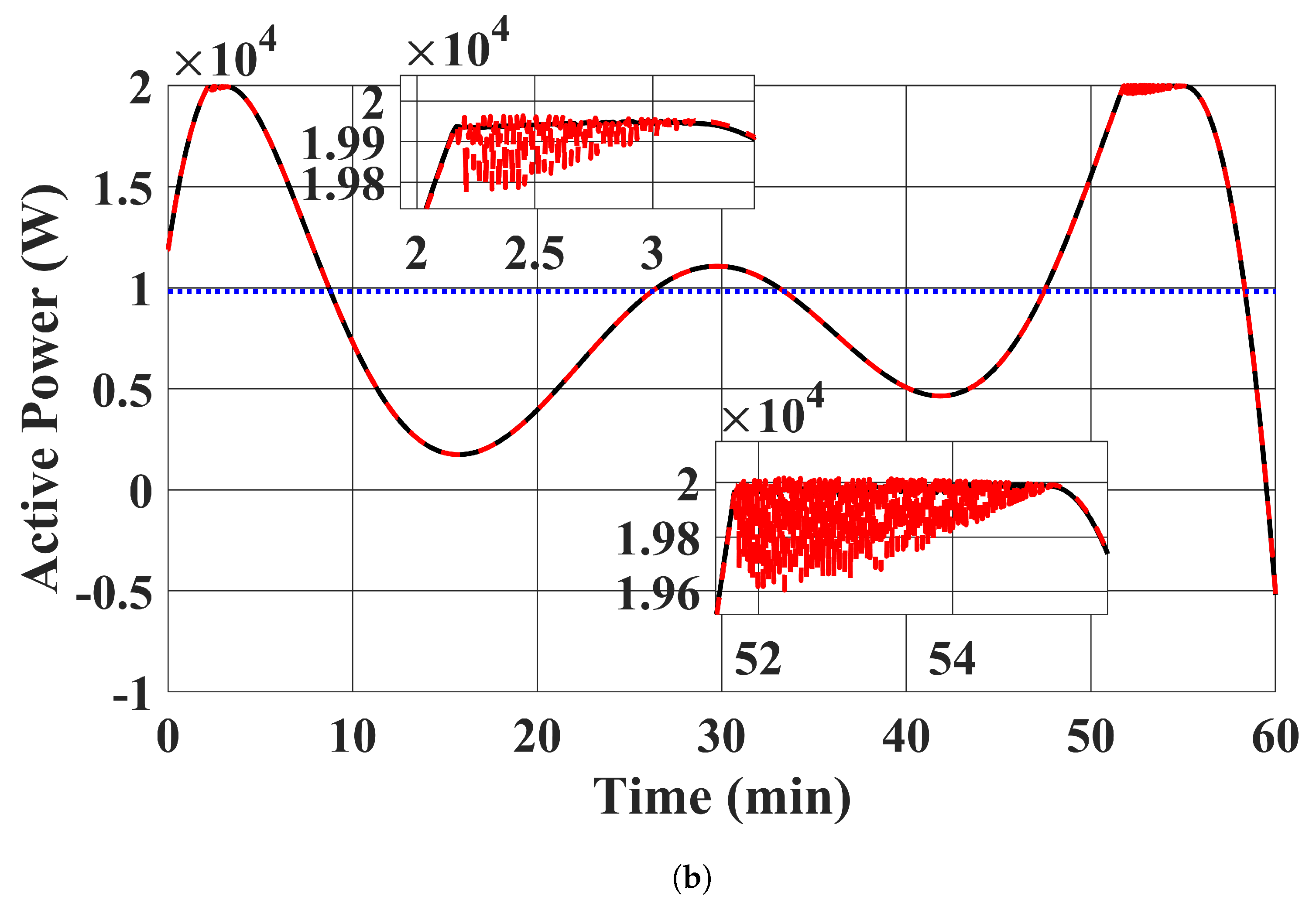
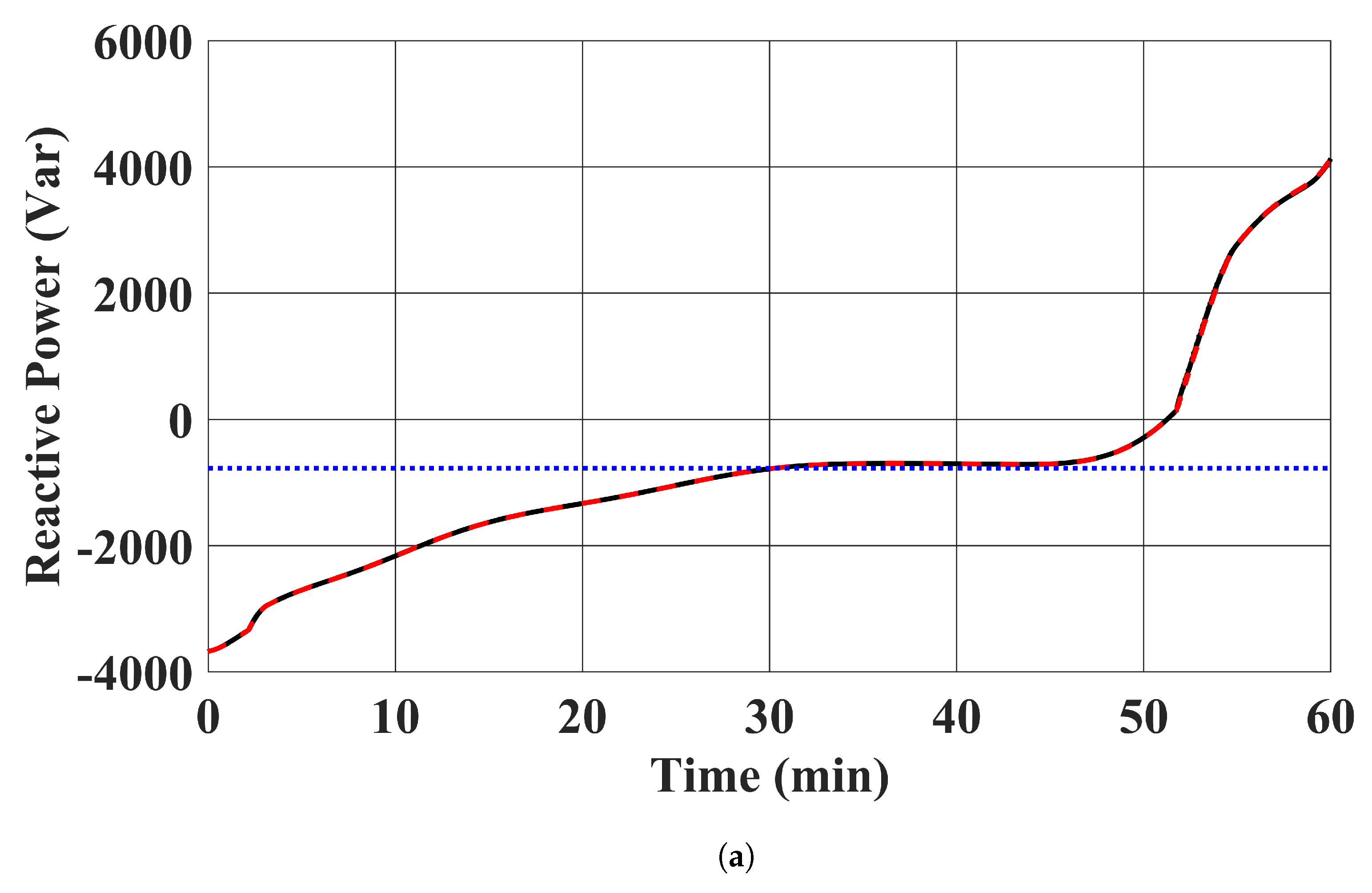
6.1.2. Electric Vehicle Chargers

EV chargers’ active power outputs, reactive power outputs, apparent power outputs, and the state of charge of the EV batteries are shown in Figure 7, Figure 8, Figure 9 and Figure 10. The trajectories of the power outputs using our proposed controller in case 1 tightly track with the benchmark optimal solution in (13) in case 2. E V 1 was charged in the simulation, while E V 2 delivered energy to the distribution system. This is desirable, as the state of charge of E V 1 was low at the beginning and charged to over 20 kWh at the end of the simulation. The limits of power output were also satisfied. It should be noted that the active and reactive power injections of the EV chargers remained constant in case 3. This is expected, as case 3 demonstrates the existing approach to fix the power injection command within each time window.

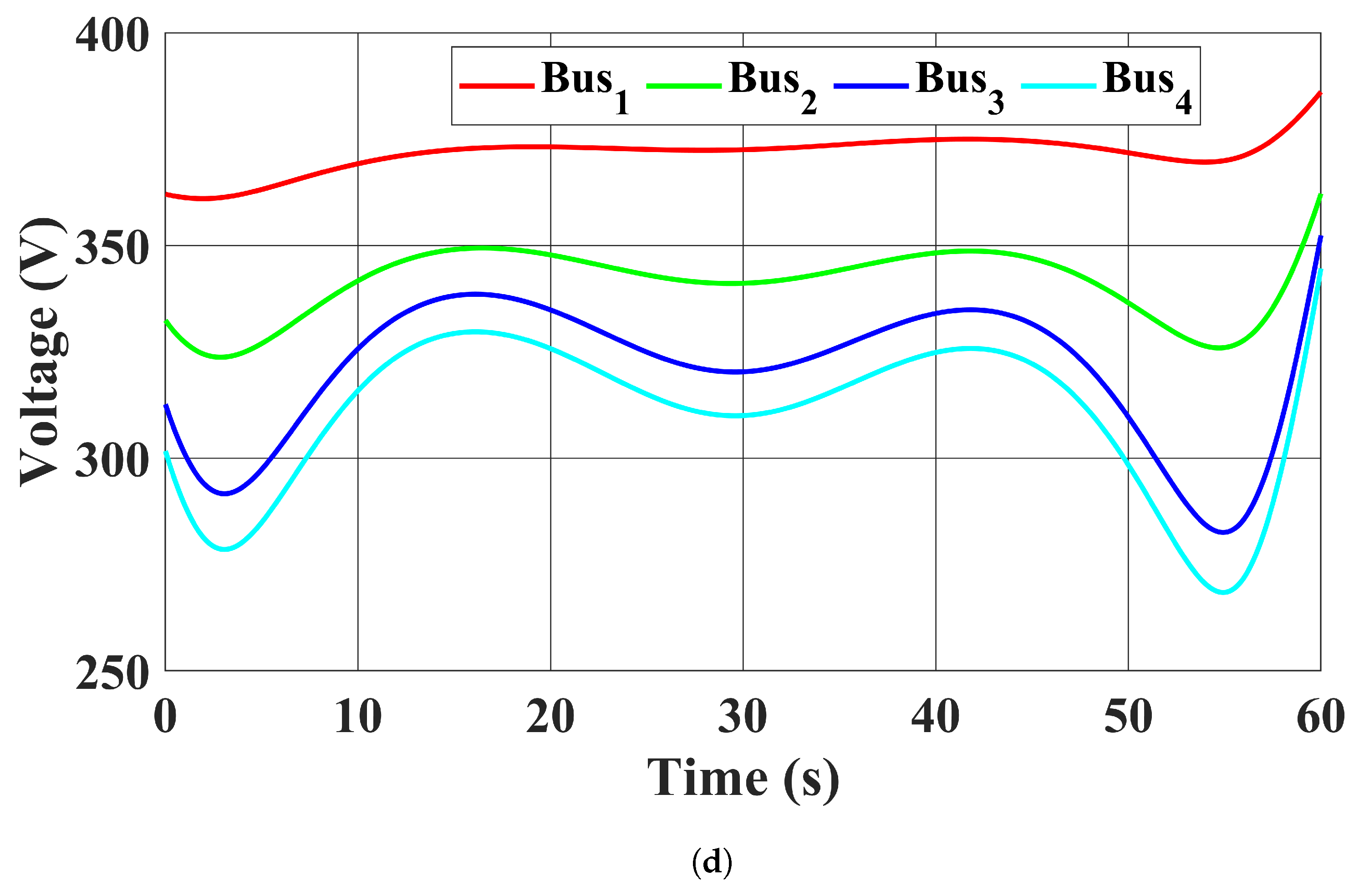
6.1.3. Bus Voltage Magnitudes

Figure 11 shows the bus voltage magnitudes in all four cases. The trajectories of the bus voltage magnitudes in case 1 with the proposed controller were close to the benchmark solution in case 2. It should be noted that although the voltage profiles were improved in case 3 compared to case 4, where the EV chargers were charged uncoordinatedly, the CB 3 voltage magnitude still fluctuated. The voltage profile in case 3 demonstrates the drawback of having a long time window to update the EV chargers’ power injections, i.e., their capability to deal with the fast bus voltage magnitude fluctuations from RESs was neglected. On the other hand, our proposed controller in case 1 promptly controlled the EV chargers to regulate the CB 3 voltage magnitude.

6.2. Discussion

The optimality of our proposed method can be shown by comparing the system trajectories between the proposed controller in case 1 and the benchmark solution in case 2. It can be seen that the trajectories are close to each other, thereby demonstrating the optimality of the proposed controller.
Our proposed method offers a new way to control RESs to track their power setpoints while avoiding potential control conflict with other controllable devices. RESs are generally controlled independently as grid-following inverters, i.e., cascaded PI controllers are used to drive the power outputs of the RESs to follow their setpoints. There is a lack of coordination between the grid-following inverters and other controllable devices. On the other hand, our proposed method formulates the control actions of the RESs and other controllable devices in the same optimization framework to properly operate them in a coordinated way to avoid the control conflict between them.
The disadvantage of having a long time window in updating the control signals to the EV chargers has been demonstrated in the CB 3 voltage magnitude regulation performance in case 3. Although the CB 3 voltage magnitude was close to 400 V on average and improved compared to case 4, the constant EV chargers’ power injections still cannot address its volatility. It can be seen that its fluctuation was over 40 V in the case study.
The necessity of coordinated EV charging has been demonstrated in case 4, where EVs were charged uncoordinatedly. The bus voltage magnitude profile severely deteriorated in case 4.

7. Conclusions

A distributed FO-based controller for EV chargers and RESs has been proposed. It coordinates EV chargers to offer real-time grid ancillary services, i.e., CB voltage magnitude regulation, while steering the RESs to their power setpoints and keeping the variables within their limits. Simulation results show that the proposed controller can tightly drive the operating point of the distribution system to the optimal solution of the prescribed optimization problem, and the bus voltage regulation performance is greatly improved. Other control targets can be easily incorporated into the optimization framework in the proposed controller and will be considered in future work.

Author Contributions

Conceptualization, Y.C.; Methodology, Y.C.; Software, Y.C.; Validation, Y.C.; Formal analysis, Y.C.; Investigation, Y.C.; Resources, Y.C.; Writing—original draft, Y.C.; Writing—review & editing, T.W.C.; Visualization, Y.C.; Supervision, T.W.C.; Project administration, Y.C.; Funding acquisition, Y.C. All authors have read and agreed to the published version of the manuscript.

Funding

This project is partially funded by Hong Kong Innovation and Technology Fund (ITF) (ref: PRP/084/20AI).

Institutional Review Board Statement

Not applicable.

Informed Consent Statement

Not applicable.

Data Availability Statement

Data are contained within the article.

Conflicts of Interest

The authors declare no conflict of interest.

Correction Statement

This article has been republished with a minor correction to the Funding statement. This change does not affect the scientific content of the article.

References

  1. Lesser, J.A.; Su, X. Design of an economically efficient feed-in tariff structure for renewable energy development. Energy Policy 2008, 36, 981–990. [Google Scholar] [CrossRef]
  2. Pyrgou, A.; Kylili, A.; Fokaides, P.A. The future of the Feed-in Tariff (FiT) scheme in Europe: The case of photovoltaics. Energy Policy 2016, 95, 94–102. [Google Scholar] [CrossRef]
  3. Alizamir, S.; de Véricourt, F.; Sun, P. Efficient feed-in-tariff policies for renewable energy technologies. Oper. Res. 2016, 64, 52–66. [Google Scholar] [CrossRef]
  4. Liu, W.; Placke, T.; Chau, K. Overview of batteries and battery management for electric vehicles. Energy Rep. 2022, 8, 4058–4084. [Google Scholar] [CrossRef]
  5. Yong, J.Y.; Ramachandaramurthy, V.K.; Tan, K.M.; Mithulananthan, N. A review on the state-of-the-art technologies of electric vehicle, its impacts and prospects. Renew. Sustain. Energy Rev. 2015, 49, 365–385. [Google Scholar] [CrossRef]
  6. Ding, N.; Prasad, K.; Lie, T.T. The electric vehicle: A review. Int. J. Electr. Hybrid Veh. 2017, 9, 49–66. [Google Scholar] [CrossRef]
  7. Kumar, M.S.; Revankar, S.T. Development scheme and key technology of an electric vehicle: An overview. Renew. Sustain. Energy Rev. 2017, 70, 1266–1285. [Google Scholar] [CrossRef]
  8. Zheng, Y.; Hill, D.J.; Meng, K.; Hui, S. Critical bus voltage support in distribution systems with electric springs and responsibility sharing. IEEE Trans. Power Syst. 2016, 32, 3584–3593. [Google Scholar] [CrossRef]
  9. Chen, T.; Zhang, X.P.; Wang, J.; Li, J.; Wu, C.; Hu, M.; Bian, H. A Review on Electric Vehicle Charging Infrastructure Development in the UK. J. Mod. Power Syst. Clean Energy 2020, 8, 193–205. [Google Scholar] [CrossRef]
  10. Srdic, S.; Lukic, S. Toward extreme fast charging: Challenges and opportunities in directly connecting to medium-voltage line. IEEE Electrif. Mag. 2019, 7, 22–31. [Google Scholar] [CrossRef]
  11. Ashfaq, M.; Butt, O.; Selvaraj, J.; Rahim, N. Assessment of electric vehicle charging infrastructure and its impact on the electric grid: A review. Int. J. Green Energy 2021, 18, 657–686. [Google Scholar] [CrossRef]
  12. Gan, L.; Topcu, U.; Low, S.H. Optimal decentralized protocol for electric vehicle charging. IEEE Trans. Power Syst. 2012, 28, 940–951. [Google Scholar] [CrossRef]
  13. Zhang, Y.; You, P.; Cai, L. Optimal charging scheduling by pricing for EV charging station with dual charging modes. IEEE Trans. Intell. Transp. Syst. 2018, 20, 3386–3396. [Google Scholar] [CrossRef]
  14. Ding, T.; Zeng, Z.; Bai, J.; Qin, B.; Yang, Y.; Shahidehpour, M. Optimal electric vehicle charging strategy with Markov decision process and reinforcement learning technique. IEEE Trans. Ind. Appl. 2020, 56, 5811–5823. [Google Scholar] [CrossRef]
  15. Liu, C.; Chau, K.; Wu, D.; Gao, S. Opportunities and challenges of vehicle-to-home, vehicle-to-vehicle, and vehicle-to-grid technologies. Proc. IEEE 2013, 101, 2409–2427. [Google Scholar] [CrossRef]
  16. Clement-Nyns, K.; Haesen, E.; Driesen, J. The impact of vehicle-to-grid on the distribution grid. Electr. Power Syst. Res. 2011, 81, 185–192. [Google Scholar] [CrossRef]
  17. Tan, K.M.; Ramachandaramurthy, V.K.; Yong, J.Y. Integration of electric vehicles in smart grid: A review on vehicle to grid technologies and optimization techniques. Renew. Sustain. Energy Rev. 2016, 53, 720–732. [Google Scholar] [CrossRef]
  18. Pirouzi, S.; Latify, M.A.; Yousefi, G.R. Conjugate active and reactive power management in a smart distribution network through electric vehicles: A mixed integer-linear programming model. Sustain. Energy Grids Netw. 2020, 22, 100344. [Google Scholar] [CrossRef]
  19. Xu, B.; Zhang, G.; Li, K.; Li, B.; Chi, H.; Yao, Y.; Fan, Z. Reactive power optimization of a distribution network with high-penetration of wind and solar renewable energy and electric vehicles. Prot. Control. Mod. Power Syst. 2022, 7, 51. [Google Scholar] [CrossRef]
  20. Wang, Y.; Qiu, D.; Strbac, G.; Gao, Z. Coordinated electric vehicle active and reactive power control for active distribution networks. IEEE Trans. Ind. Inform. 2022, 19, 1611–1622. [Google Scholar] [CrossRef]
  21. El-Bayeh, C.Z.; Alzaareer, K.; Brahmi, B.; Zellagui, M. A novel algorithm for controlling active and reactive power flows of electric vehicles in buildings and its impact on the distribution network. World Electr. Veh. J. 2020, 11, 43. [Google Scholar] [CrossRef]
  22. Colombino, M.; Dall’Anese, E.; Bernstein, A. Online optimization as a feedback controller: Stability and tracking. IEEE Trans. Control. Netw. Syst. 2019, 7, 422–432. [Google Scholar] [CrossRef]
  23. Hauswirth, A.; Bolognani, S.; Hug, G.; Dörfler, F. Timescale separation in autonomous optimization. IEEE Trans. Autom. Control. 2020, 66, 611–624. [Google Scholar] [CrossRef]
  24. Bianchin, G.; Cortés, J.; Poveda, J.I.; Dall’Anese, E. Time-varying optimization of LTI systems via projected primal-dual gradient flows. IEEE Trans. Control. Netw. Syst. 2021, 9, 474–486. [Google Scholar] [CrossRef]
  25. Menta, S.; Hauswirth, A.; Bolognani, S.; Hug, G.; Dörfler, F. Stability of dynamic feedback optimization with applications to power systems. In Proceedings of the 2018 56th Annual Allerton Conference on Communication, Control, and Computing (Allerton), Monticello, IL, USA, 2–5 October 2018; IEEE: Piscataway, NJ, USA, 2018; pp. 136–143. [Google Scholar]
  26. Todescato, M.; Simpson-Porco, J.W.; Dörfler, F.; Carli, R.; Bullo, F. Online distributed voltage stress minimization by optimal feedback reactive power control. IEEE Trans. Control. Netw. Syst. 2017, 5, 1467–1478. [Google Scholar] [CrossRef]
  27. Ortmann, L.; Hauswirth, A.; Caduff, I.; Dörfler, F.; Bolognani, S. Experimental validation of feedback optimization in power distribution grids. Electr. Power Syst. Res. 2020, 189, 106782. [Google Scholar] [CrossRef]
  28. Picallo, M.; Ortmann, L.; Bolognani, S.; Dörfler, F. Adaptive real-time grid operation via Online Feedback Optimization with sensitivity estimation. Electr. Power Syst. Res. 2022, 212, 108405. [Google Scholar] [CrossRef]
  29. Ortmann, L.; Rubin, C.; Scozzafava, A.; Lehmann, J.; Bolognani, S.; Dörfler, F. Deployment of an Online Feedback Optimization Controller for Reactive Power Flow Optimization in a Distribution Grid. arXiv 2023, arXiv:2305.06702. [Google Scholar]
  30. Zhan, S.; Morren, J.; van den Akker, W.; van der Molen, A.; Paterakis, N.G.; Slootweg, J. Fairness-incorporated Online Feedback Optimization for Real-time Distribution Grid Management. IEEE Trans. Smart Grid 2023, 15, 1792–1806. [Google Scholar] [CrossRef]
  31. Ortmann, L.; Maeght, J.; Panciatici, P.; Dörfler, F.; Bolognani, S. Online Feedback Optimization for Transmission Grid Operation. arXiv 2022, arXiv:2212.07795. [Google Scholar]
  32. Carnevale, G.; Mimmo, N.; Notarstefano, G. Nonconvex Distributed Feedback Optimization for Aggregative Cooperative Robotics. arXiv 2023, arXiv:2302.01892. [Google Scholar]
  33. Terpin, A.; Fricker, S.; Perez, M.; de Badyn, M.H.; Dörfler, F. Distributed feedback optimisation for robotic coordination. In Proceedings of the 2022 American Control Conference (ACC), Atlanta, GA, USA, 8–10 June 2022; IEEE: Piscataway, NJ, USA, 2022; pp. 3710–3715. [Google Scholar]
  34. Olives-Camps, J.C.; del Nozal, Á.R.; Mauricio, J.M.; Maza-Ortega, J.M. A model-less control algorithm of DC microgrids based on feedback optimization. Int. J. Electr. Power Energy Syst. 2022, 141, 108087. [Google Scholar] [CrossRef]
  35. Cheng, Y.; Liu, T.; Hill, D.J. Distributed feedback optimization in fully inverter based islanded microgrids for accurate reactive power sharing and fast response in P - f Droop. In Proceedings of the 12th IET International Conference on Advances in Power System Control, Operation and Management (APSCOM 2022), Hong Kong, China, 7–9 November 2022; Volume 2022, pp. 234–239. [Google Scholar] [CrossRef]
  36. Cheng, Y.; Liu, T.; Hill, D.J. Distributed feedback optimisation based optimal power flow control in fully inverter based islanded AC microgrids. IET Smart Grid 2023, 6, 572–584. [Google Scholar] [CrossRef]
  37. Al-Ogaili, A.S.; Hashim, T.J.T.; Rahmat, N.A.; Ramasamy, A.K.; Marsadek, M.B.; Faisal, M.; Hannan, M.A. Review on scheduling, clustering, and forecasting strategies for controlling electric vehicle charging: Challenges and recommendations. IEEE Access 2019, 7, 128353–128371. [Google Scholar] [CrossRef]
  38. Mukherjee, J.C.; Gupta, A. A review of charge scheduling of electric vehicles in smart grid. IEEE Syst. J. 2014, 9, 1541–1553. [Google Scholar] [CrossRef]
  39. Amjad, M.; Ahmad, A.; Rehmani, M.H.; Umer, T. A review of EVs charging: From the perspective of energy optimization, optimization approaches, and charging techniques. Transp. Res. Part D Transp. Environ. 2018, 62, 386–417. [Google Scholar] [CrossRef]
  40. Pasha, J.; Li, B.; Elmi, Z.; Fathollahi-Fard, A.M.; Lau, Y.y.; Roshani, A.; Kawasaki, T.; Dulebenets, M.A. Electric Vehicle Scheduling: State of the Art, Critical Challenges, and Future Research Opportunities. J. Ind. Inf. Integr. 2024, 38, 100561. [Google Scholar] [CrossRef]
  41. Jiang, W.; Zhen, Y. A real-time EV charging scheduling for parking lots with PV system and energy store system. IEEE Access 2019, 7, 86184–86193. [Google Scholar] [CrossRef]
  42. Bouhouras, A.S.; Kothona, D.; Gkaidatzis, P.A.; Christoforidis, G.C. Distribution network energy loss reduction under EV charging schedule. Int. J. Energy Res. 2022, 46, 8256–8270. [Google Scholar] [CrossRef]
  43. Khodayar, M.E.; Wu, L.; Li, Z. Electric vehicle mobility in transmission-constrained hourly power generation scheduling. IEEE Trans. Smart Grid 2013, 4, 779–788. [Google Scholar] [CrossRef]
  44. Yong, J.Y.; Ramachandaramurthy, V.K.; Tan, K.M.; Mithulananthan, N. Bi-directional electric vehicle fast charging station with novel reactive power compensation for voltage regulation. Int. J. Electr. Power Energy Syst. 2015, 64, 300–310. [Google Scholar] [CrossRef]
  45. Pogaku, N.; Prodanovic, M.; Green, T.C. Modeling, Analysis and Testing of Autonomous Operation of an Inverter-Based Microgrid. IEEE Trans. Power Electron. 2007, 22, 613–625. [Google Scholar] [CrossRef]
  46. Kersting, W.H. Distribution System Modeling and Analysis; CRC Press: London, UK, 2017. [Google Scholar]
  47. Bidram, A.; Lewis, F.L.; Davoudi, A. Distributed control systems for small-scale power networks: Using multiagent cooperative control theory. IEEE Control. Syst. Mag. 2014, 34, 56–77. [Google Scholar]
Figure 1. Configuration of the EV charger and its output connector.
Sustainability 16 02432 g001
Figure 2. Configuration of the RES and its output connector.
Sustainability 16 02432 g002
Figure 3. The four-bus distribution system. The red dotted arrows refer to the communication links.
Sustainability 16 02432 g003
Figure 4. RESs’ MPPT profiles. (a) R E S 1 . (b) R E S 2 .
Sustainability 16 02432 g004
Figure 5. RESs’ MPPT profiles tracking performance of the proposed controller in case 1. (a) R E S 1 . (Black: MPPT profile; Red: case 1 proposed controller was used). (b) R E S 2 . (Black: MPPT profile; Red: case 1 proposed controller was used).
Sustainability 16 02432 g005aSustainability 16 02432 g005b
Figure 6. RESs’ reactive power injections with the proposed controller in case 1. (a) R E S 1 . (b) R E S 2 .
Sustainability 16 02432 g006aSustainability 16 02432 g006b
Figure 7. EV chargers’ active power injections. (a) E V 1 . (Red: case 1 proposed controller was used; Black: case 2 benchmark optimal solution in (13); Blue: case 3 power injections of EV chargers were fixed to the average value in case 2). (b) E V 2 . (Red: case 1 proposed controller used; Black: case 2 benchmark optimal solution in (13); Blue: case 3 power injections of EV chargers were fixed to the average value in case 2).
Sustainability 16 02432 g007aSustainability 16 02432 g007b
Figure 8. EV chargers’ reactive power injections. (a) E V 1 . (Red: case 1 proposed controller was used; Black: case 2 benchmark optimal solution in (13); Blue: case 3 power injections of EV chargers were fixed to the average value in case 2). (b) E V 2 . (Red: case 1 proposed controller used; Black: case 2 benchmark optimal solution in (13); Blue: case 3 power injections of EV chargers were fixed to the average value in case 2).
Sustainability 16 02432 g008aSustainability 16 02432 g008b
Figure 9. EV chargers’ apparent power injections. (a) E V 1 . (Red: case 1 proposed controller was used; Black: case 2 benchmark optimal solution in (13); Blue: case 3 power injections of EV chargers were fixed to the average value in case 2). (b) E V 2 . (Red: case 1 proposed controller used; Black: case 2 benchmark optimal solution in (13); Blue: case 3 power injections of EV chargers were fixed to the average value in case 2).
Sustainability 16 02432 g009aSustainability 16 02432 g009b
Figure 10. EV battery energy storage using the proposed controller. (a) E V 1 . (b) E V 2 .
Sustainability 16 02432 g010aSustainability 16 02432 g010b
Figure 11. Bus voltage magnitudes. (a) Case 1: The proposed controller was used. (b) Case 2: Benchmark optimal solution in (13). (c) Case 3: EV chargers power injections were fixed to the average value in case 2. (d) Case 4: EVs were charged at the full rate of 20,000 W, and the reactive power injections of EV chargers were set to zero.
Sustainability 16 02432 g011aSustainability 16 02432 g011bSustainability 16 02432 g011c
Disclaimer/Publisher’s Note: The statements, opinions and data contained in all publications are solely those of the individual author(s) and contributor(s) and not of MDPI and/or the editor(s). MDPI and/or the editor(s) disclaim responsibility for any injury to people or property resulting from any ideas, methods, instructions or products referred to in the content.

