1. Introduction
With the sustainable development of the world’s industry, the power system is also changing from fossil energy to clean energy, such as solar and wind [
1]. As a result, hybrid microgrids have become an increasingly popular way of supplying electricity due to their reliability and operational efficiency [
2]. Microgrids are the integration of distributed generations (DGs), energy storage devices, power electronic converters, and loads into a single system [
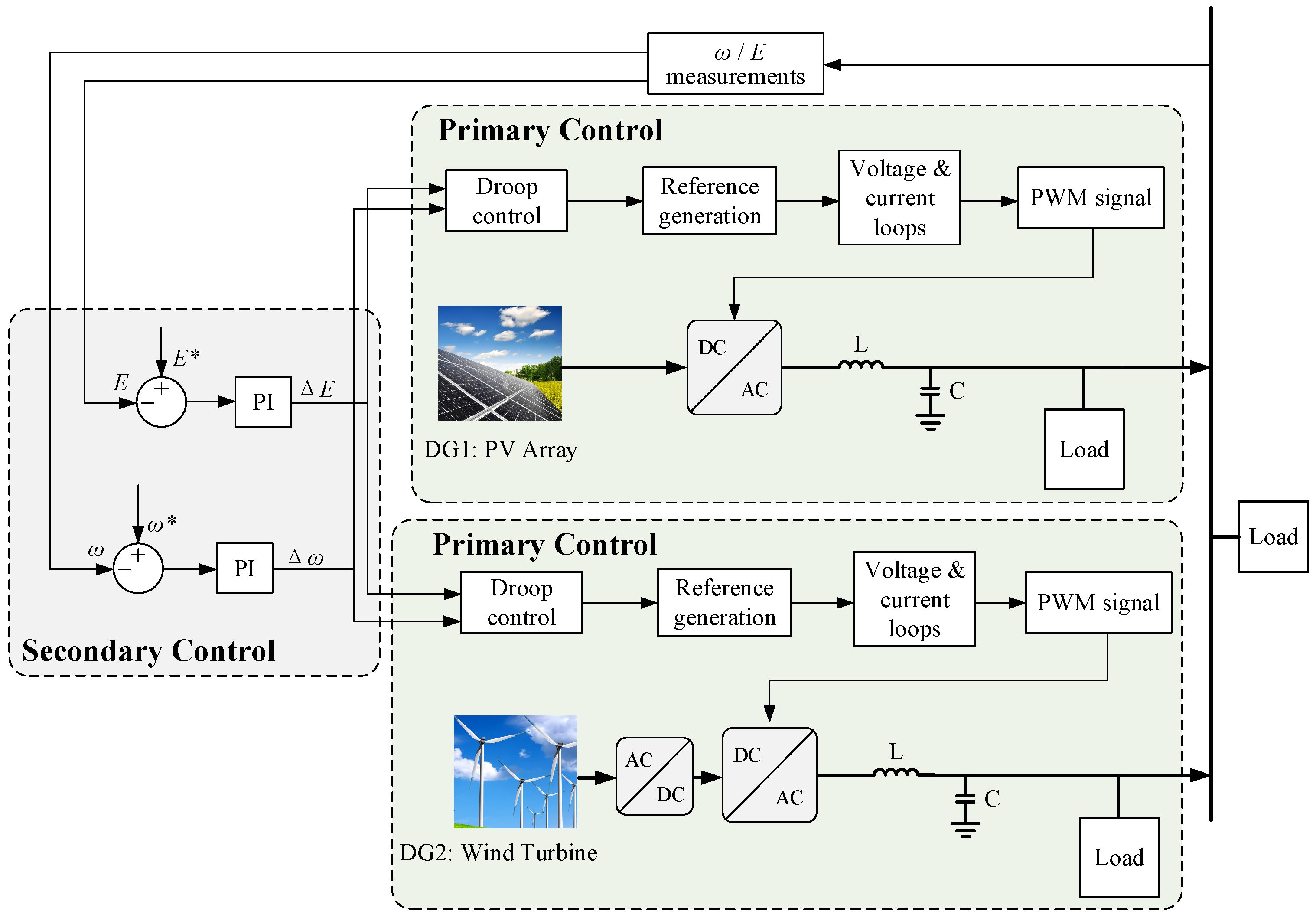
3]. Microgrids are used in power grid applications for saving energy and reducing emissions, making environmental protection very favorable. The inputs of microgrids include photovoltaic, wind, and micro-diesel generators and other electrical energy, and the outputs comprise the voltage, frequency, and energy flows of microgrids. Its control requirements include system stability, response speed, and fault tolerance. Hierarchical control is the main method used for microgrids, and its control technology has become increasingly mature, with studies [
4,
5,
6,
7] adopting a hierarchical control structure for microgrids, primary control mainly using droop control to achieve stabilization of the microgrid output voltage and frequency, secondary control compensating for the drop caused by droop control, and the tertiary control carrying out the economic dispatch and energy management.
The study by [
8] proposes a two-layer hierarchical optimization approach for a microgrid community energy management system in a smart grid environment. Ref. [
9] proposes a hierarchical energy management system to address the issues of energy trading, network interconnection, and the intermittency of renewable energy sources. Ref. [
10] presents a hierarchical control scheme for islanded AC microgrids, which has droop control and centralized extended optimal tidal current control. Ref. [
11] proposes a hierarchical control scheme utilizing a new control loop to control reactive power references through a nonlinear fuzzy logic controller. From the above literature studies, it can be seen that the hierarchical control method and its application for microgrids are very mature, so the microgrid in this study also adopts a hierarchical control structure.
Due to the lack of optimal configuration and optimal operation, the implementation of microgrids often lacks economic and environmental benefits. Based on this, microgrids need to rapidly coordinate the control of source–storage–load with intraday or real-time adjustments at the coordinated control layer and local control layer to ensure stable operation and maximize clean energy utilization [
12]. Therefore, the entire microgrid system must be analyzed and designed to operate in a stable region [
13]. Numerous studies used multi-objective optimization algorithms to optimize the operation of microgrids in their tertiary control [
14,
15,
16,
17]. Ref. [
18] proposed a self-optimizing droop control strategy based on optimal operating conditions to improve the overall operational performance of the system. Ref. [
19] proposed a multi-objective selection optimization method to optimize the combined economic–environmental benefits of grid-connected microgrids.
In the study by [
20], a multi-objective microgrid energy optimization model was developed using the beetle antenna search algorithm to optimize energy management and scheduling for microgrids of renewable energy, conventional energy, and energy storage systems. Ref. [
21] proposed a multi-objective particle swarm optimization algorithm for archive update mechanism based on nearest neighbour approach. Ref. [
22] proposed a new multi-objective rectification strategy to improve the load frequency control of islanded microgrids. Ref. [
23] introduced a new critical load vector microgrid optimization design methodology to find the desired balance between microgrid power availability, net present value cost, and power efficiency. Ref. [
24] proposed a two-step multi-objective hybrid battery storage system management approach by hybridizing two battery storage systems for shipboard microgrids. From all these studies, it can be seen that there are various multi-objective optimization methods for microgrids; however, the objectives of their concern are different. In this study, we optimize the economic cost, environmental cost, and the degree of energy utilization, and a particle swarm algorithm with a stronger global search capability and faster convergence is used.
There are also some related research studies about the particle swarm algorithm. In relation to this, ref. [
25] established a multi-objective optimization mathematical model based on the comprehensive consideration of economy, environment, and battery cycle power in the microgrid scheduling process. Ref. [
26] proposed a meta-heuristic hybrid algorithm, i.e., a hybrid frog leaping algorithm (SFLA) and particle swarm optimization algorithm (PSO), for solving a multi-objective optimal power flow while considering multi-fuel constraints. Ref. [
27] explored the use of the integrated learning particle swarm optimization algorithm and differential evolutionary algorithm in a fuzzy frame to solve the optimal active scheduling (OAPD) problem. Based on the fuzzy mathematical theory, a fuzzy multi-objective optimization model with associated constraints minimizes the total economic cost and network losses of microgrids [
28]. Ref. [
29] considers the microgrid power output and carbon emission constraints in the grid-connected mode. The optimal model to reduce carbon emission cost and optimize economic operation is proposed.
Particle global optimization and external file maintenance strategies are designed to improve the load distribution capability of traditional multi-objective particle swarm optimization [
30], which also optimizes the decision maker’s preference for the objective through a fuzzy decision-making scheme. Ref. [
31] established a multi-objective hierarchical optimization model based on considering the comprehensive impact of DG access and the importance of loads, and taking the optimal microgrid operation economics as the objective function.
The above articles show that the particle swarm algorithm utilizes its full advantage in microgrid optimization, and has been widely applied to the multi-objective optimization of microgrids. However, the traditional particle swarm algorithm still has some deficiencies. In the conventional particle swarm algorithm, the values of inertia weight
and the learning factors
and
are fixed, which leads to the traditional particle swarm addressing not being comprehensive. Thus, it is easy to fall into the local optimal problem. However, this study introduces the variable inertia weight and the learning factors to improve the particle swarm algorithm in multi-objective optimization. Compared to the above studies in [
26,
27], the modified PSO is more sensitive to population initialization and is also prone to produce locally optimal solutions when the initial population distribution greatly varies. The modified particle swarm algorithm is more advantageous in multi-objective optimization and can produce a better optimization effect for microgrids. The main contributions of this study are as follows:
- (1)
The introduction of variable inertia weight and learning factors to improve the particle swarm algorithm for the uncertain system scenarios in microgrids due to the stochastic nature of power generation and load demand. Its operation resulted in better optimization of the tertiary control of the microgrid, reduced energy losses, increased utilization of renewable energy, and enabled the microgrid to operate in a more economical manner.
- (2)
The microgrid model is built in Simulink for simulations, and the microgrid is controlled by hierarchical control, which contains primary control and secondary control to realize the stable operation of the microgrid. Then, the data of the power scheduling process of the modified particle swarm algorithm are imported into the microgrid model in Simulink, and the results verify that the modified particle swarm algorithm can be applied to the microgrid.
- (3)
Starting from the market environment and the natural environment, respectively, the changes in the microgrids affected by the external environment are further studied. It is verified that there is a contradiction between the optimization of microgrid economy and environmental protection. Moreover, microgrids need to adjust their optimization focus according to the natural conditions in order to obtain a better operation scheme.
3. Tertiary Control Optimization Methods: Particle Swarm Algorithms
The multi-objective scheduling scheme of the wind–photovoltaic (PV)–diesel–storage microgrid system studied in this paper considers three indicators, namely its economic cost, energy utilization degree, and environmental cost in the islanded state. A multi-objective microgrid model containing PV generators, wind turbines, diesel engines, and storage batteries is established.
3.1. Construction of Microgrid System Scheduling Model Based on Particle Swarm Algorithm
3.1.1. Wind–PV–Diesel–Storage Microgrid Contribution Model of Each Component
According to the characteristics of each component’s output, the output model is analyzed as follows:
The power of the wind turbine is determined by the wind speed of the region where it is located and the rated power of the generator. The output model expression is as follows:
where
is the rated power of the wind turbine,
is the cut-in wind speed, and
is the cut-out wind speed. When the wind speed is less than the cut-in wind speed or greater than the cut-out wind speed, the turbine power will be 0. When the wind speed is between the rated wind speed and the cut-out wind speed, the turbine power will keep the rated power unchanged.
The power of PV is mainly related to the light intensity and ambient temperature in its region, and the expression of the output model is as follows:
where
is the output power measured under rated conditions;
is the irradiation intensity under rated conditions;
is the irradiation intensity at a certain time;
is the reference temperature, taking 25 °C;
is the surface temperature of the solar panel at a certain time; and
k is the power temperature coefficient. From Equation (6), it can be seen that the power generation of solar cells as well as light intensity and ambient temperature are positively correlated.
Diesel generator output is more stable than that of wind and PV, and it is mainly used as a reliable guarantee in power generation scheduling to maintain normal operation of the microgrid in the case of insufficient new energy output. Its operating power can be kept constant or adjusted between the maximum and minimum power according to the load change to meet the demand. The diesel engine output model is expressed as follows:
where
is the fuel absorption rate,
is the rated power of the diesel engine,
is the actual output power of the diesel engine, and
and
are the correlation coefficients of the diesel generator fuel absorption curve. Diesel generator fuel absorption can be inverted through the diesel generator power generation.
Wind power generation units and PV power generation units are greatly affected by weather and climate, resulting in uncertainty in their power output, which can easily have an impact on the power grid and deteriorate its power quality. Therefore, the energy storage unit is indispensable for the microgrid. Battery is currently the most mature technology of a battery energy storage technology, with high energy density, stable energy supply, and high cycle efficiency [
32]. In this paper, the battery is used as an energy storage device. Its output is related to the battery capacity and deep discharge, which can discharge when the load is not met, charge and store electric energy when the power exceeds the load, and play the role of peak cutting and valley filling. The model is as follows:
where
is the battery capacity,
and
are the charging and discharging powers, respectively,
and
are the charging and discharging efficiencies,
S is the rated capacity of the battery, and
is the time step.
3.1.2. Objective Function
Microgrid optimization scheduling needs to consider a number of indicators in order to achieve a more optimal performance while meeting the demand load. There are three optimization indexes measured in this paper. One of which is the economic cost, the second is the degree of energy utilization, and the third is the environmental cost. The main objective of this paper is to achieve the goal of minimizing the combination of economic cost, wind, and PV waste rate and environmental pollution by rationally allocating the current generation capacity of each generation unit. The overall objective function is as follows:
where
Fnc is the economic cost, which mainly takes into account the generation cost, maintenance cost, battery deep charging/discharging cost, and abandonment/shortage cost of each generation unit; the calculation formula is as follows:
where
UE is the degree of energy utilization, which is mainly used to measure the degree of utilization of clean energy by microgrids, and its expression is a linear comprehensive function of the respective absorption rates of wind and PV power generation as follows:
where
and
are the PV absorption rate and wind absorption rate, respectively, and their values are the ratios of the total amount of generation utilized by the current dispatch scheme to the total amount of generation predicted to be available on that day, both of which are in the range of [0, 1]. Due to the target optimization seeking the minimum value, the degree of energy utilization indicators in the processing of 2 minus the sum of the wind and PV absorption ratio was chosen in order to ensure that the results were positive at the same time, so that the value of the degree of energy utilization became negatively correlated, that is, the smaller the result of the numerical value of the wind and PV integrated rate of absorption of the higher, the higher the degree of energy utilization. The value range of the final data is [0, 2].
Green is the cost of environmental protection, which identifies the amount of pollutant gases generated during the diesel power generation process, which is calculated as the cost of treating the main harmful gases (including
CO2,
SO2, and
NOx) generated by the diesel engine per unit of power generation, with the following expression:
where
,
, and
are the governance costs of
CO2,
SO2 and
NOx, respectively, which are calculated as follows:
where
is the cost of treating each kilogram of pollutant,
k in the subscript represents three different pollutant gases, and
represents the pollutant emission when the output power of diesel engine is
P.
Since optimal scheduling needs to be solved using intelligent algorithms, measuring the three indicators requires extending the exploration space of the algorithms to three dimensions—which is difficult in model building—while the convergence speed of the algorithms may slow down considerably—which is not conducive to algorithmic optimization. A simplified mindset was adopted by combining the environmental and economic aspects into a single indicator—financial environmental cost (FEC).
In the study by Linjing Hu et al., ref. [
33] considers wind/PV stability with two performance indicators: loss of power supply probability (
LPSP) and energy waste rate (
EWR). In order to improve the convergence speed, the two metrics are combined into a single metric
LE that is balanced with a custom parameter α, which is shown as follows:
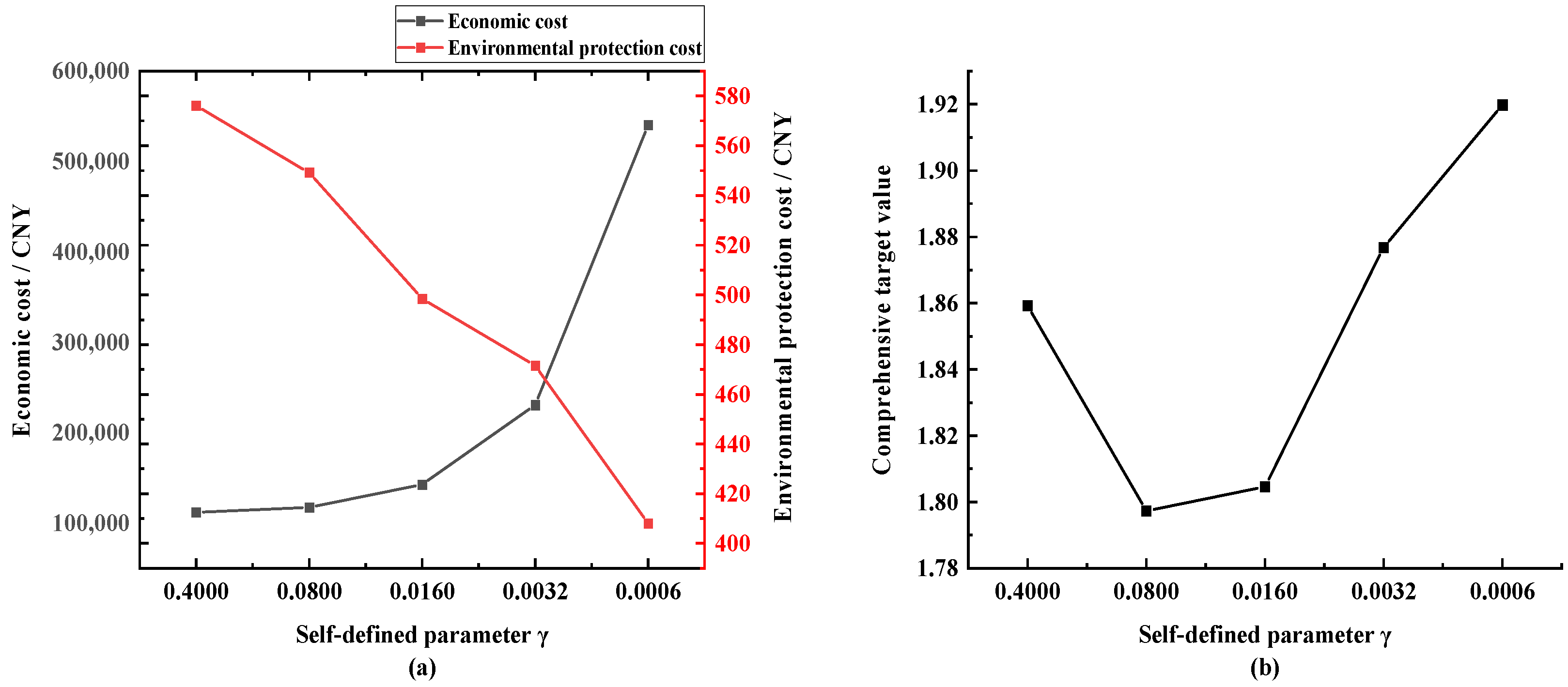
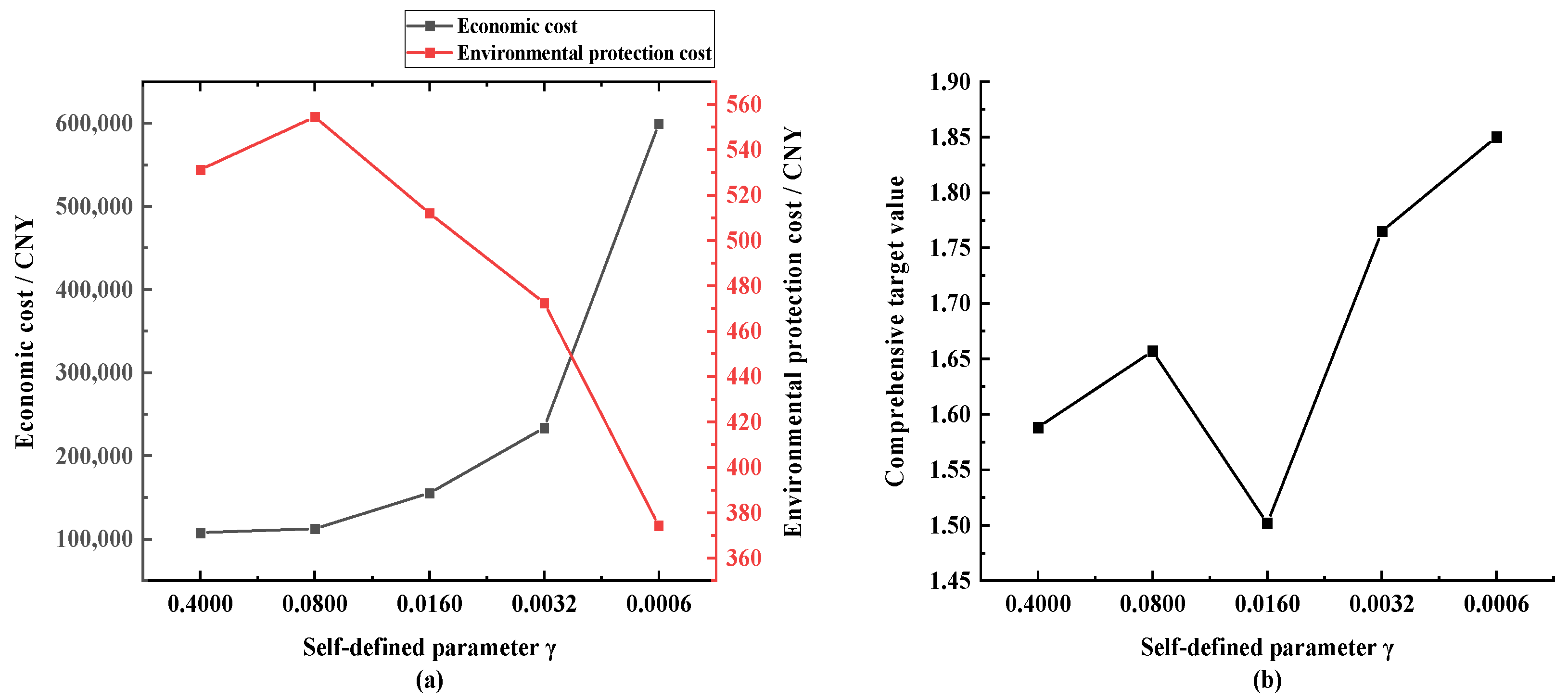
This section draws on this methodology by similarly treating economic cost and environmental cost by summing the costs incurred by both and introducing customized parameters
for balancing, with the following expressions:
The parameters can be changed to adjust the weight of the two components and modify the focus of the microgrid optimization scheme according to the overall needs of the grid. Therefore, the multi-objective expression of the final system is as follows:
3.1.3. Restrictive Condition
- 1.
Constraint of Generator Set
In terms of the actual configuration of the microgrid, it is necessary to consider the capacity of each power generation component to ensure that the capacity of each PV generator set is reasonable. In the case of being able to satisfy the load, the scale of the configured equipment should not be too large to save space and economic costs.
Constraints on PV unit output:
Constraints on wind turbine output:
Constraints on diesel generator sets:
- 2.
Battery Operation Constraints
The energy storage unit has the role of peak shaving and valley filling. When the power grid generates excess power in the low valley, the energy storage unit stores energy. When the power grid generates insufficient power in the high peak, the energy storage device releases energy, which effectively improves the economy of the system operation, reduces the waste of energy, and also regulates the power fluctuation of the load. In this paper, the battery is used as the energy storage device, and its working state has two kinds of charging and discharging. The maximum charging capacity is expressed as a negative number, and the maximum discharging capacity is expressed as a positive number.
The output constraints are as follows:
The capacity constraints are as follows:
where
is the current battery capacity,
is the maximum capacity of battery deep discharge, and
is the maximum capacity of battery charging.
- 3.
Generation Margin Constraints
The generation margin is the sum of the difference between the dispatched generation and the expected load, and its calculation expression is as follows:
where
is the microgrid dispatch generation at moment
i,
is the expected load value at moment
i, and the two are accumulated to obtain the difference between the dispatch generation and the overall expected load in a day.
In order to ensure the reliability of the grid generation, it is necessary to limit the difference between the generation and the expected load not to exceed a certain limit, with the following constraints:
3.2. Research and Improvement of Particle Swarm Algorithm
In the conventional particle swarm algorithm, the values of inertia weight and learning factors , are fixed, which leads to the problem that the traditional particle swarm addressing is not comprehensive and easily falls into the local optimal solution. In order to improve this defect and make the addressing range more extensive, it is necessary to introduce parameter values that change with the increase in the number of iterations, which gives rise to the improved particle swarm algorithm. The basic goal to be achieved by the parameter changes is to make the particle swarm tend to learn autonomously in the early iteration, thus expanding the range of movement of the particle swarm, and to make the particle swarm tend to learn socially in the late iteration, thus accelerating the convergence speed and obtaining the global relative optimal solution.
There are many ways and methods of parameter change guided by this concept, such as linear change and adaptive change. The former mainly realizes the parameter change by presetting the initial and final values of the parameters, and then specifying the linear function that changes with the number of iterations, while the latter needs to consider the current particle’s fitness and the average fitness, and continuously corrects the parameters through screening. In this paper, the linearly varying inertia weight and learning factors are used, and are formulated as follows:
where
is the number of iterations;
is the maximum number of iterations;
,
, and
are the initial values of inertia weight, self-learning factor, and community learning factor, respectively; and
,
, and
are their final values, respectively.
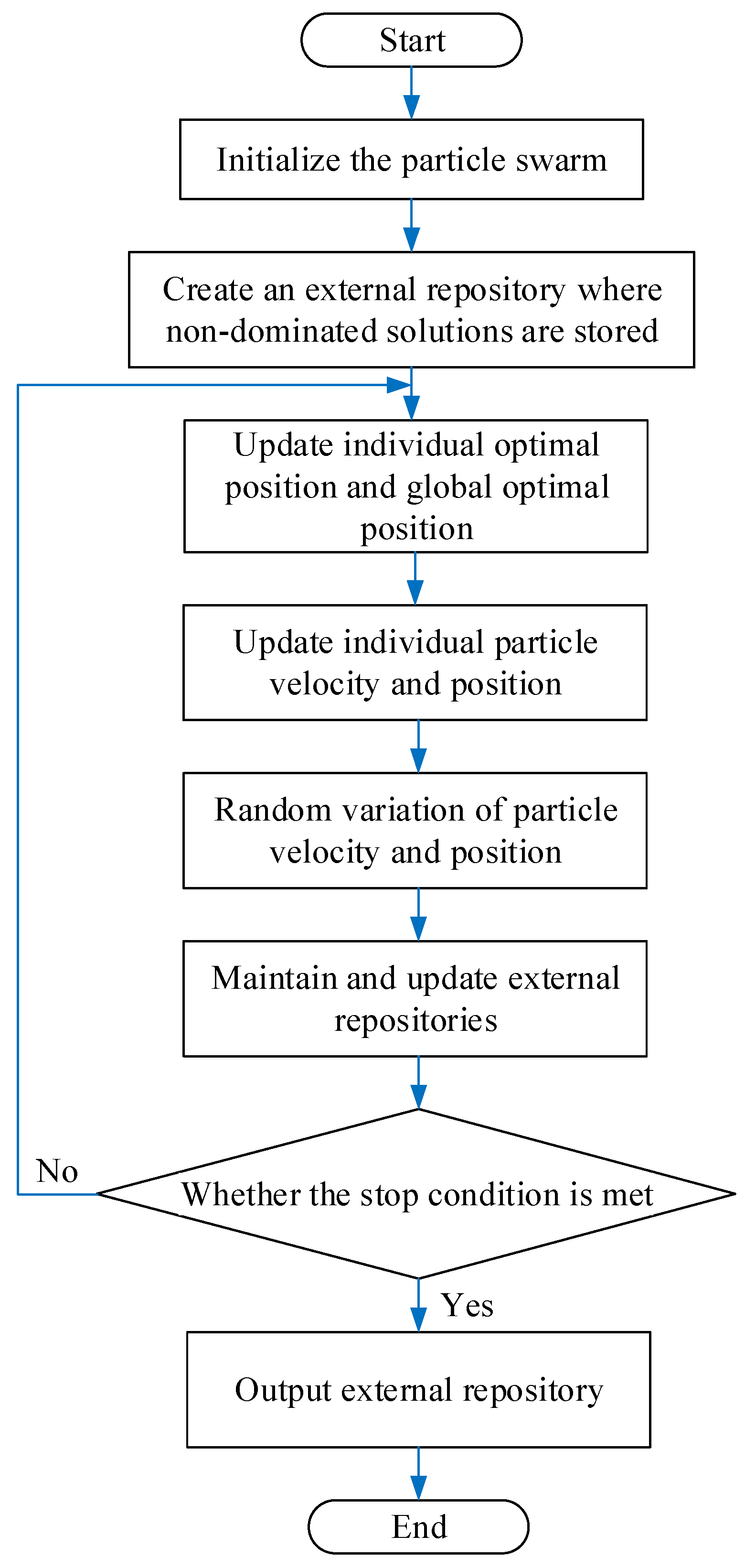
The modified particle swarm algorithm sets up an external repository in order to filter and store the particles that meet the requirements. The particles in the repository determine the particle swarm moving state, and the addition and deletion of particles in the repository are accomplished by the adaptive grid method. The current optimal solution of the swarm is selected by roulette. The search range is divided into grids, each grid is numbered, and the grid to which each particle belongs is labeled by the serial number, and finally the non-dominated solution of the particle is randomly selected from the grid to determine the current optimal position of the particle. Each particle is also randomly mutated during the iteration process, floating up and down the current range to increase the diversity of particles. The final repository holds a series of nondominated solutions as output data, and the final result is subsequently rationalized by selecting the final result based on a trade-off formula determined by the prioritization of the microgrid objectives. The flowchart of the modified particle swarm algorithm is given below (
Figure 2).
4. Simulation Results and Discussions
4.1. Particle Swarm Algorithm Simulation
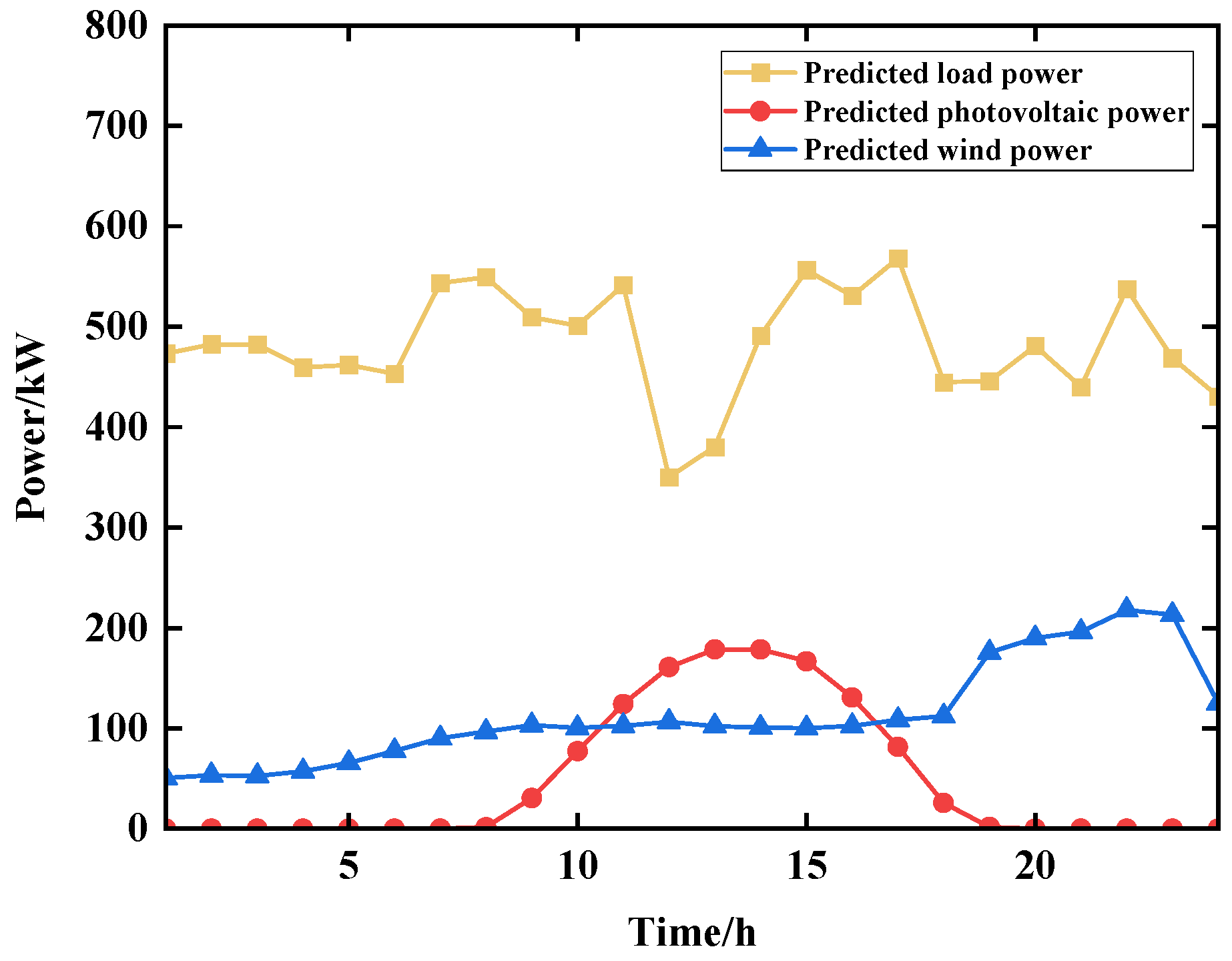
In this study, the Pareto optimal solution theory is adopted to solve the multi-objective optimal scheduling problem of microgrids; the traditional particle swarm and improved particle swarm algorithms are used as the intelligent optimization algorithms; and the data of a power grid in East China are used as the simulation data. The wind power, PV, and load prediction curves in this region are shown in
Figure 3. The configuration of the diesel engine unit generates power in the range of 100–400 kW, the maximum charging power of the energy storage battery pack is −200 kW, and the maximum discharging power is 250 kW. The predicted load demand is in the range of 300–600 kW. The whole microgrid can meet the predicted load.
A series of nondominated solutions obtained after addressing of particle swarm algorithm is used to obtain the final scheduling result by weighted summation method. All the objective values are normalized and assigned according to the weight. Finally, the particle with the smallest combined value after summation is taken as the optimal solution, i.e., a compromise solution is searched for as the final scheduling solution. The formula is as follows:
where
,
, and
are the weight of each objective value;
,
, and
are the corresponding maxima in the set of non-dominated solutions for each objective value, respectively.
4.2. Traditional Particle Swarm Algorithm Simulation
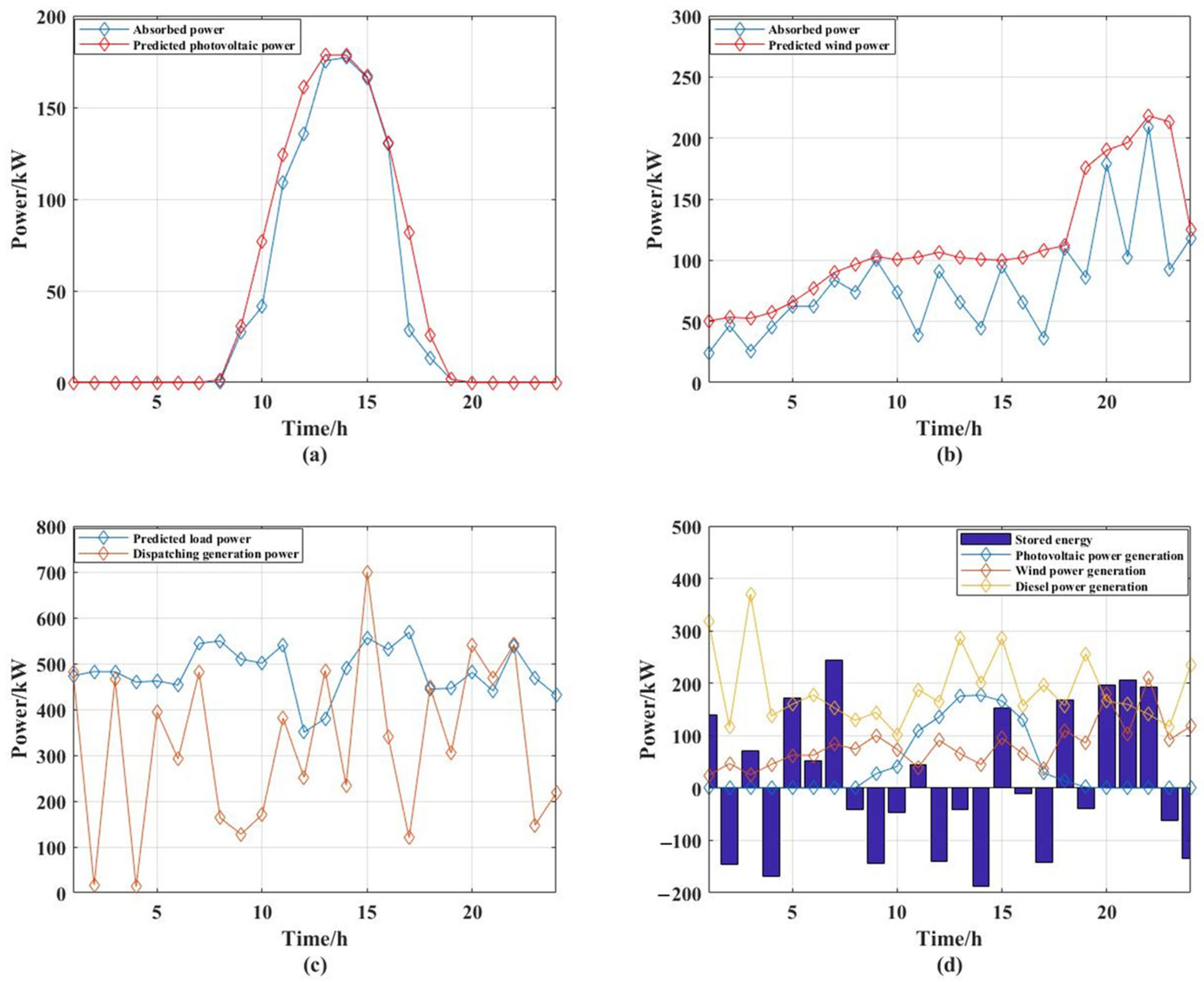
The particle swarm algorithm program is built according to the traditional particle swarm characteristics and is implemented in Matlab 2020b. Based on its standard value range, the parameter values are selected after reasonable testing. The final inertia weight is set to 0.5, the self-learning factor is set to 0.1, the community learning factor is set to 0.2, and the number of iterations is 100. The execution time is 30.009 s. The simulation results are shown in
Figure 4.
The values of the indicators: the degree of energy utilization is 0.7452; the rate of PV absorption is 0.6578; and the rate of wind absorption is 0.5970; the financial environmental cost is RMB 135,870; the economic cost is RMB 135,380; and the environmental cost is RMB 491.569.
The large values obtained for the energy utilization degree indicator indicate that the PV and wind absorption rates are not excellent.
Figure 4a,b show that the dispatch generation of wind and PV outlets is not a very good fit to the predicted capacity.
As can be seen from
Figure 4c, the dispatched generation is lower than the predicted load and the gap is larger before 11:00, and gradually approaches the predicted load after 13:00, but there are still some moments when the generation is too low.
From
Figure 4d, it can be seen that the diesel engines are more powerful throughout the whole process. Moreover, PV and wind power generation basically follow the law of unit power, but energy storage charging and discharging is more disordered, and it does not play a good role in shaving peaks and filling valleys.
4.3. Modified Particle Swarm Algorithm Simulation
The initial and final values of the inertia weight of the modified particle swarm algorithm are set to 0.9 and 0.2, respectively, and the larger initial value in the early stage facilitates the global search, while the weight gradually decrease as the number of iterations increases, which is convenient for the convergence of the particle swarm. The initial and final values of the self-learning factor are 1.2 and 0.02, respectively. The initial and final values of the community learning factor are 0.01 and 1.2, respectively. The execution time is 27.882 s. The larger self-learning factor and smaller community learning factor in the early stage can reduce the external influences on the particles, which is conducive to the wide range of activities within the feasible range and the global search; the smaller self-learning factor and larger community learning factor in the later stage can increase the particle’s ability to follow the global optimum, which is more conducive to the particle localization of the optimal solution. The simulation results are shown in
Figure 5.
The values of the indicators: energy utilization degree is 0.4159; the PV absorption rate is 0.8683; wind absorption rate is 0.7158; the financial environmental cost is RMB 132,230; the economic cost is RMB 131,690; the environmental cost is RMB 533.454.
The value of energy utilization degree is low, indicating that the performance is better. It can also be seen from
Figure 5a,b that the fit between the dispatched generation and the predicted generation is very high, which is significantly better than the traditional particle swarm scheduling results. It can be seen that the diesel power generation in the mid-day PV power generation out of the more significant decline, PV power generation is concentrated in the 9:00–17:00 of the mid-day moment, and wind power generation is concentrated in the 18:00–23:00 of the sunset and nighttime moments: the two form a staggered peak complementary effect.
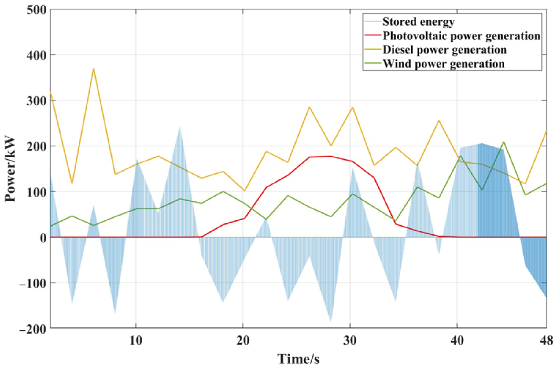
Figure 5c,d show the energy storage battery in the PV and wind power generation peak charging and reducing the power generation. With the diesel engine working, there is a better peak that enables the valley to be filled, stabilizing the microgrid power supply.
4.4. Comparative Analysis of Conventional Particle Swarm Algorithm and Modified Particle Swarm Algorithm Simulation
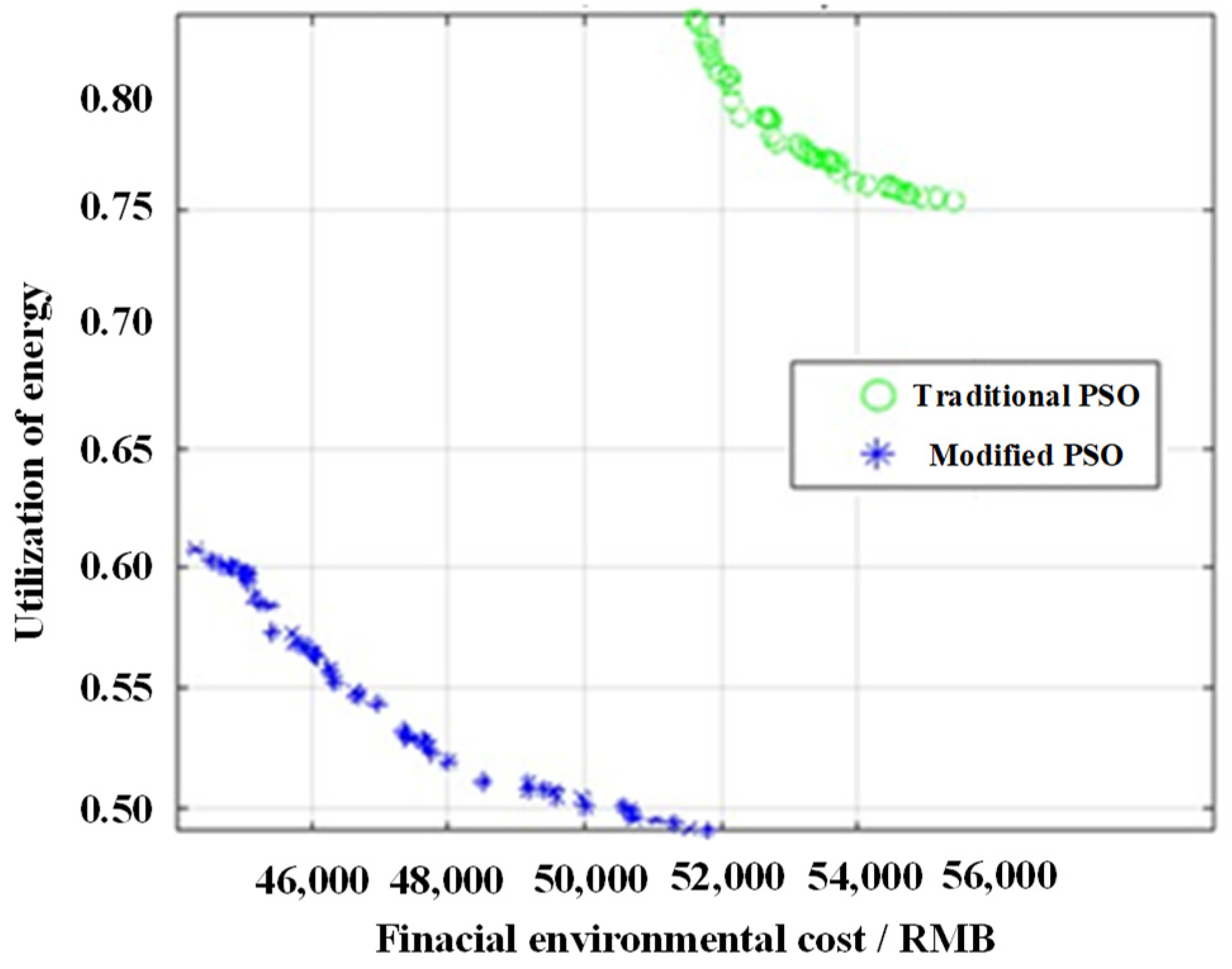
The respective Pareto frontier surfaces of the conventional particle swarm and the modified particle swarm algorithm can be shown by the particle positions in the external repository. As shown in
Figure 6, it can be seen that the frontier surface of the modified particle swarm algorithm was advanced in comparison to the conventional particle swarm by the two objective terms stipulated in Equation (16). Moreover, the environmental economy and the degree of energy utilization were optimized, so the solution set of the modified particle swarm algorithm dominates over the solution set of the traditional particle swarm algorithm. This means that the modified particle swarm algorithm finds a more excellent scheduling scheme.
At the same time, it can be clearly seen that the number of particles in the storage library of the modified particle swarm algorithm is large and widely distributed. Compared to the conventional particle swarm that is overly centralized and has a small number of particles, the modified particle swarm can utilize the space of the external storage library more efficiently, reduce the waste, and reduce the possibility of local convergence. The modified particle swarm algorithm has a higher convergence in the multimodal problems with a convergence rate from 33.009 s to 27.882 s, as well as simulation results yielding a better global optimal solution than the traditional PSO.
The modified particle swarm algorithm has better global search capability. Its convergence speed varies depending on the complexity of the problem and the number of optimization objectives, and the parameter settings are also crucial to its performance and convergence characteristics. The modified particle swarm algorithm can improve its convergence accuracy.
In order to compare the modified particle swarm algorithm more rigorously to the conventional particle swarm algorithm, the two algorithms are run 100 times under the same conditions. The number of each iteration is 100, and the average and optimal values of the final scheduling results are compared in the following
Table 1. Moreover, the total margin of power generation is also added to further measure the performance of scheduling scheme.
As can be seen from the data in
Table 1, the time used for 100 runs of the modified particle swarm is longer, indicating that its convergence speed is slower than that of the conventional particle swarm. However, both the average value and the optimal value of the modified particle swarm optimization objective are better than the conventional particle swarm algorithm in terms of energy utilization and economic and environmental protection. In terms of the average value, the value of economic and environmental protection is 29.5% lower than that of the conventional particle swarm. The modified particle swarm also outperforms the conventional particle swarm algorithm in terms of the difference between the dispatched generation and the predicted load. The absolute value of the total generation margin is reduced by 21.1% compared to the conventional particle swarm, which makes the power supply capacity of the microgrid more reliable.
In summary, the modified particle swarm with variable inertia weight and variable learning factors can address systems more widely, break the limitation of conventional particle swarm that is easy to converge on the local optimal solution, improve the utilization rate of the microgrid for wind and PV generation, and reduce the operating cost of the microgrid, which leads to the improved performance of the final scheduling scheme in many aspects.
4.5. Simulation of Results of Modified Particle Swarm Algorithm Runs in Simulink
The scheduling results of wind, PV, diesel, and energy storage components are saved, and then a microgrid model is constructed in Simulink, where four DGs represent PV, wind, diesel, and energy storage components, respectively. Further, the particle swarm algorithm’s process of regulating the power of each component is added to each DG, and the 24 h power regulation process is simulated as 48 s, i.e., every two seconds represents an hour, and the simulation results are described below.
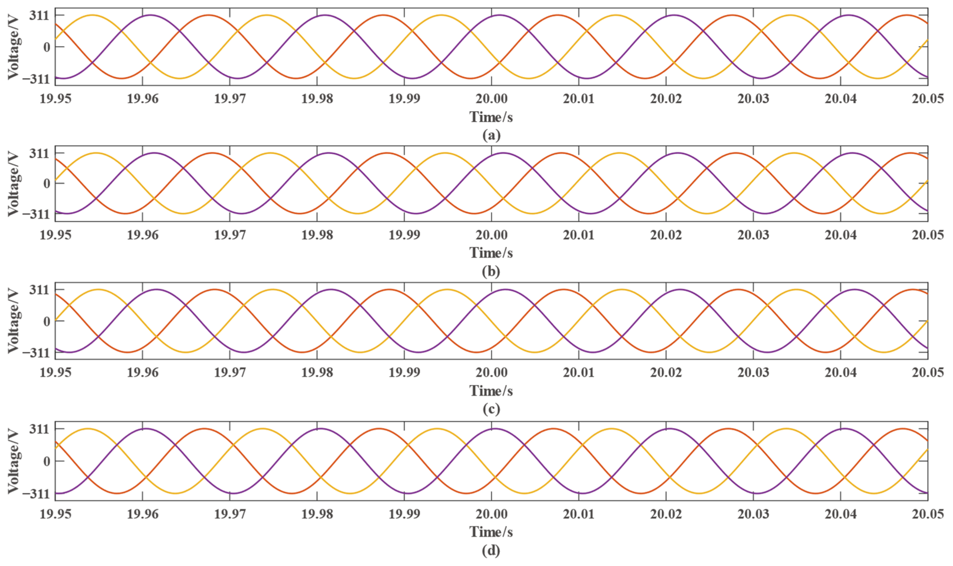
Figure 7 shows the voltages of each component of the microgrid within the period from 19.95 s to 20.05 s.
Figure 7a–d represent the voltages of the PV, wind, diesel, and storage parts, respectively. The orange, purple, and yellow lines in
Figure 7a–d represent the output three-phase voltage, respectively. It can be seen that the output voltages of each component in this time period are relatively standard three-phase sinusoidal waves, and the amplitudes are all stabilized at 311 V.
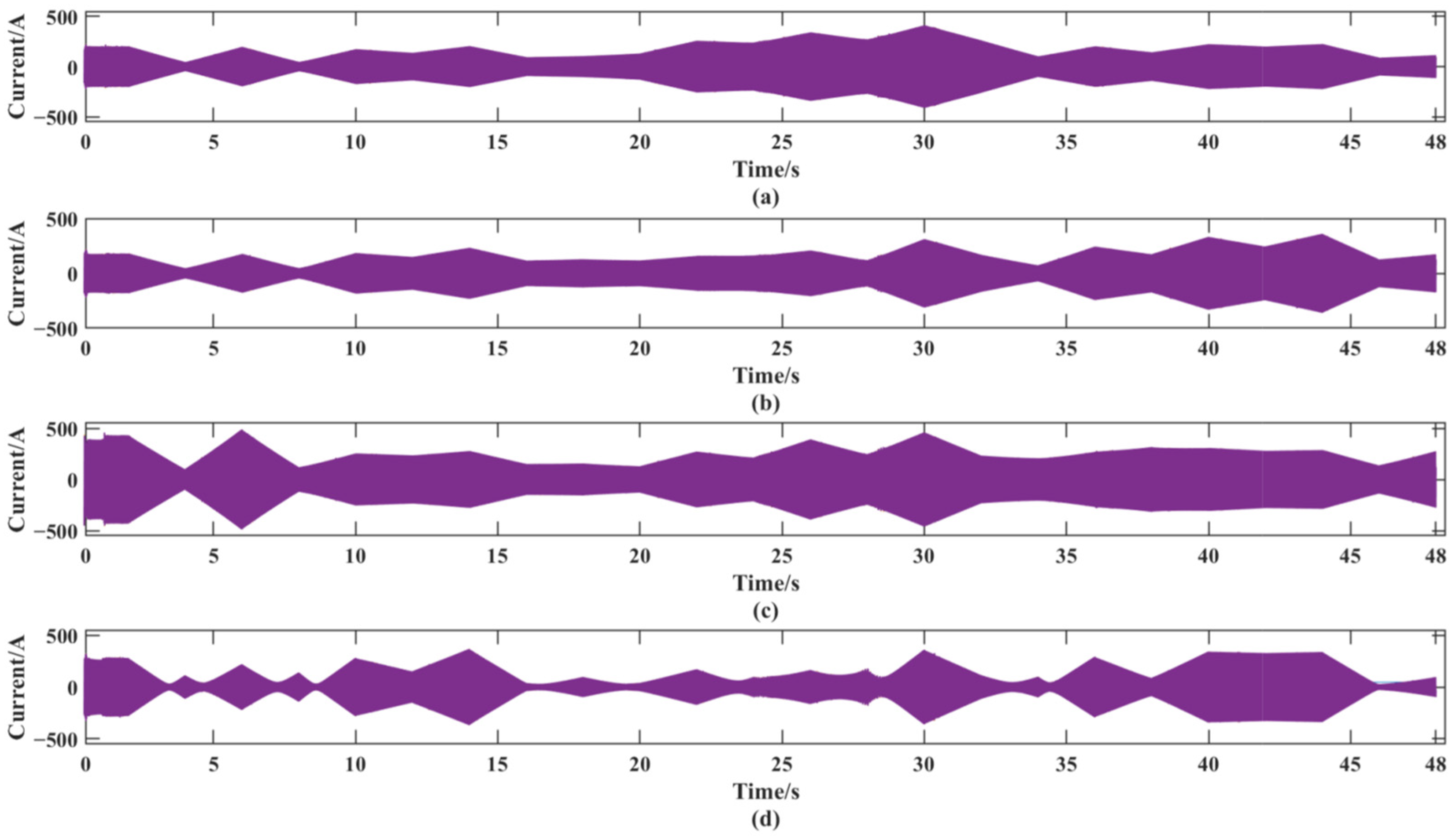
Figure 8a–d represent the currents of each component of the microgrid, and the currents of the microgrid changes continuously due to the power regulation.
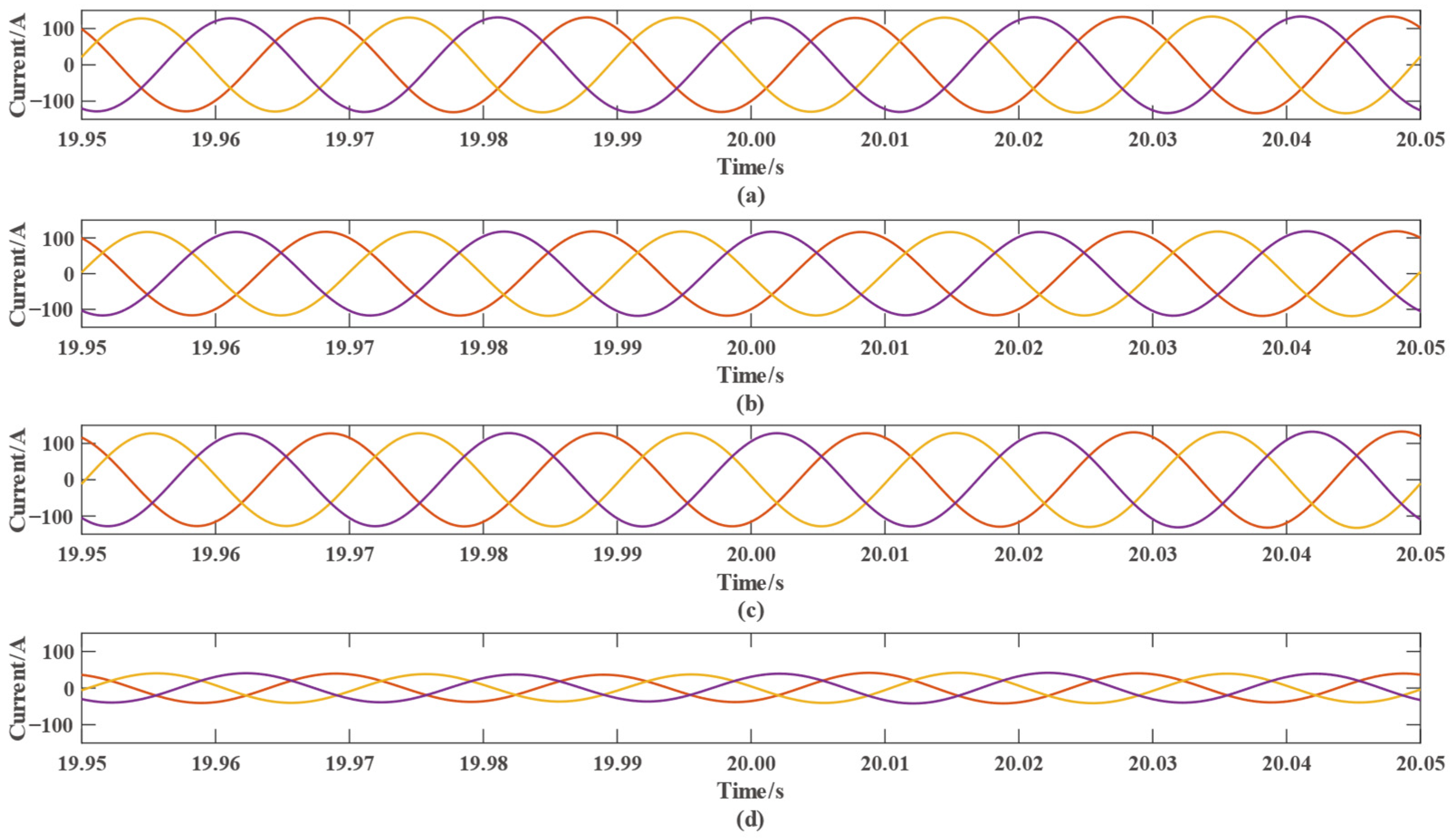
Figure 9 shows that although the currents of the microgrid change due to the power regulation of each component, the currents of each component are also three-phase sinusoidal waveforms in the time period from 19.95 s to 20.05 s. The orange, purple, and yellow lines in
Figure 8a–d represent the output three-phase current, respectively.
Figure 10a–d represent the frequencies of each component of the microgrid, and it can be seen that the frequencies of the output voltages fluctuate during power regulation, but they are all maintained near the desired frequency of 50 Hz, which indicates that the frequencies of the output voltages of the microgrid are stable.
Figure 11 represents the output power of the PV, wind, diesel, and energy storage section, respectively. It can be seen by comparing this figure to
Figure 5d, the output power is able to change according to the preset regulation process, which indicates that the modified particle swarm algorithm is able to carry out power scheduling in the microgrid model.
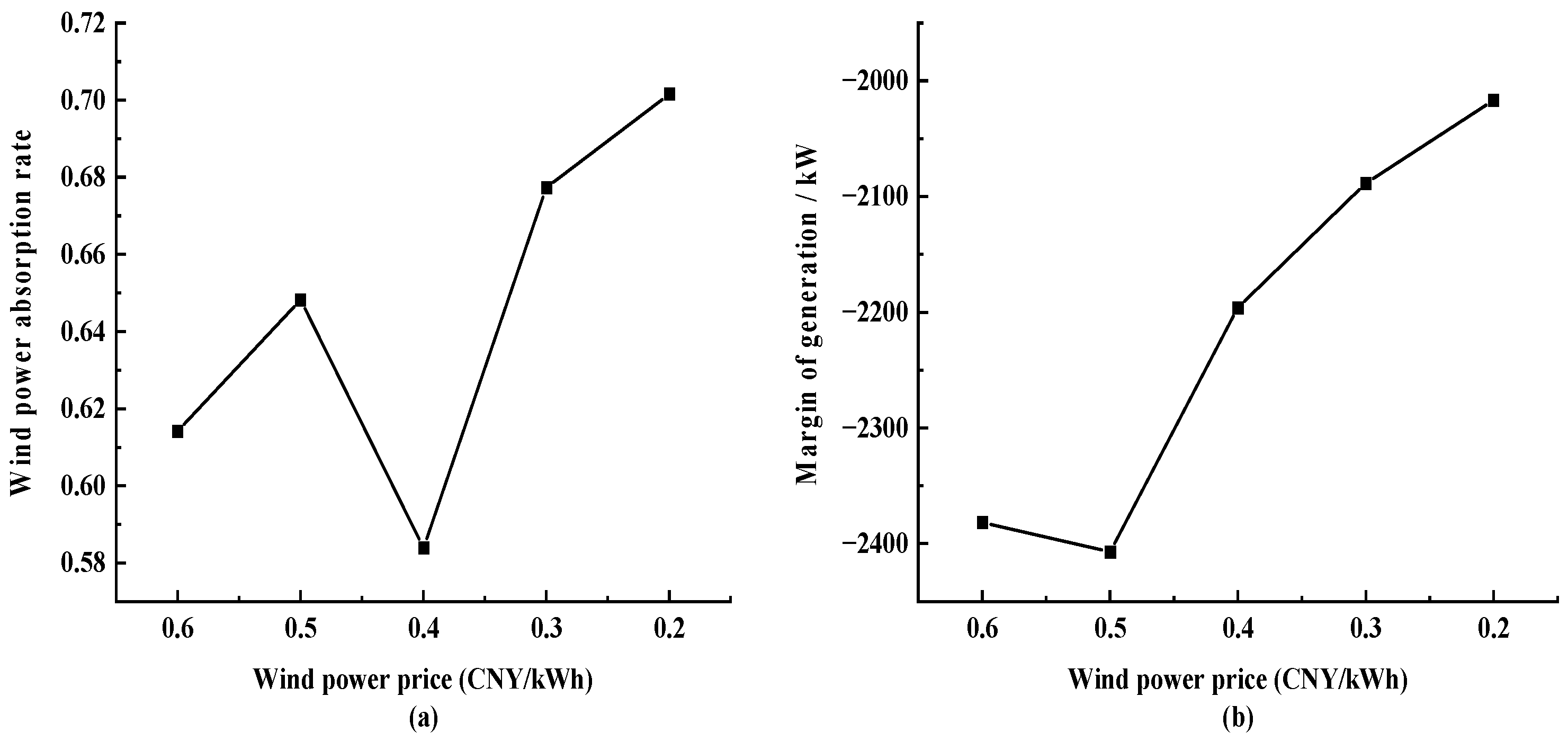
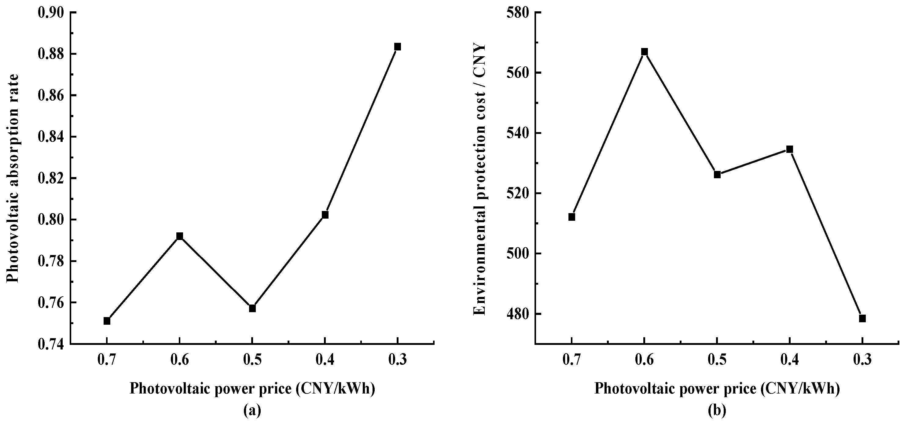
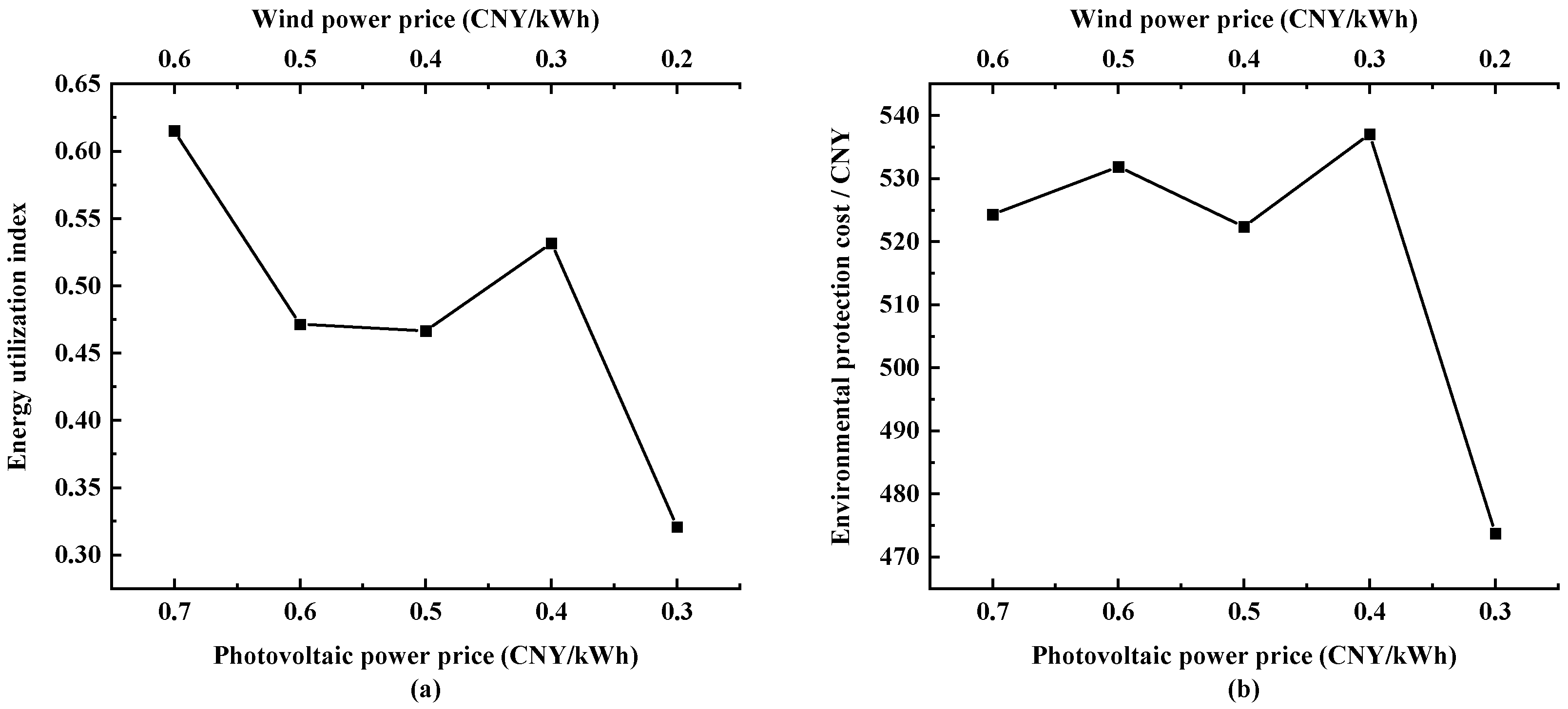
6. Conclusions
From the above simulation results, it can be understood that the modified particle swarm algorithm obtained through the introduction of variable inertia weight and learning factors has a higher utilization rate of external storage libraries and a better global convergence. Moreover, as the microgrid’s photovoltaic absorbed rate increases from 0.7724 to 0.8683 and wind energy absorbed rate from 0.6064 to 0.7158, a 14.89% increase in energy utilization and a reduction in environmental costs from RMB 135,870 to RMB 132,230 is achieved. The microgrid model built in Simulink can output stable voltage, current, and frequency, and the simulation results verify that the modified particle swarm algorithm can be applied to microgrids. As the new energy market power generation price downward adjustment of the situation as well as change in the simulation of microgrid parameters verified that there is a conflict between the economic and environmental protection indexes by adjusting the microgrids’ wind power generation component capacity for a comparison test, we studied the impact of different capacity configurations on the optimization results of microgrid scheduling. Furthermore, we verified the need to reasonably determine the value of custom parameter γ according to the actual situation of the microgrid in order to adjust the optimization strategy. However, the particle swarm algorithm still has the possibility of falling into a local optimal solution. In the future, the researchers would like to adopt a multiple restart strategy, using different random seeds, initial positions, and speeds each time. The instability of the algorithm due to different initial states can be mitigated by comparing the results of multiple independent runs. This could be performed by introducing more intelligent and flexible neighborhood search mechanisms, such as introducing changing neighborhood sizes or neighborhood shapes, as well as introducing an adaptive mechanism that allows the algorithm to automatically adjust the algorithm parameters according to the current search state.


