Article

Application of an Automated Top Coal Caving Control System: The Case of Wangjialing Coal Mine

1
School of Mining Engineering, Taiyuan University of Technology, Taiyuan 030024, China
2
State Key Laboratory for Fine Exploration and Intelligent Development of Coal Resources, China University of Mining and Technology, Xuzhou 221116, China
3
Anhui Province Wanbei Coal-Electricity Group Co., Ltd., Suzhou 234000, China
4
Key Laboratory of In-Situ Property-Improving Mining of Ministry of Education, Taiyuan University of Technology, Taiyuan 030024, China
*
Author to whom correspondence should be addressed.
Sustainability 2024, 16(10), 4261; https://doi.org/10.3390/su16104261
Submission received: 16 April 2024 / Revised: 8 May 2024 / Accepted: 15 May 2024 / Published: 18 May 2024
(This article belongs to the Section Energy Sustainability)

Abstract

:
China has made notable advancements in the intelligent construction of coal mines. However, for longwall top coal caving (LTCC) mining faces, a key obstacle impeding the intelligent transition of the coal-cutting process is automated control. This paper focuses on the aforementioned issue and comprehensively considers the pre-, intra-, and post-coal-caving stages. In this work, diverse detection and monitoring technologies are integrated at various stages through a computer platform, facilitating the construction of an automated coal caving control system with self-perception, self-learning, self-decision-making, and self-execution capabilities. Key technologies include ground-penetrating radar-based top coal thickness detection, inertial navigation-based shearer positioning, tail beam vibration-based identification of coal and gangue, and magnetostrictive sensor-based monitoring of the tail beam and insert plate attitude. In this study, the 12309 working face of the Wangjialing Coal Mine was experimentally validated, and the efficacy of the aforementioned key technologies was assessed. The results demonstrated that the control requirements for automated coal caving are satisfied by the maximum errors. Automatic regulation of coal caving was realized through the implementation of this system, thereby facilitating initiation and cessation and yielding promising experimental outcomes. Overall, this system offers practical insights for intelligent construction in current LTCC mining faces and the sustainable development of coal resources.

1. Introduction

Coal serves as the cornerstone of China’s energy security, with thick coal seams accounting for approximately 45% and 50% of the country’s total reserves and output, respectively [1,2,3]. These prominent coal seams are pivotal in ensuring a stable coal supply. Longwall top coal caving (LTCC) is a primary technique employed for mining thick coal seams, wherein the seam is vertically divided into two sections: bottom and top coal [4,5,6]. A conventional working face is then established at the location of the bottom coal, where mine pressure leads to top coal fragmentation. These fragmented particles are subsequently drawn through a cave opening integrated within the support [7,8]. However, coal caving in LTCC mining faces generally employs subjective decision-making methods such as listening and visual inspection. Automation is impeded by this dependence on manual judgment, posing a significant technological bottleneck in achieving intelligent mining in these areas [9,10,11]. However, China itself is strongly promoting intelligent coal mining. Therefore, improving the automation level of top coal caving control has become vital to intelligently upgrade LTCC mining faces and ensure sustainable development in coal mining.
The caving of crushed top coal particles through the cave opening occurs during top coal caving. Automated control technology for coal caving employs various real-time detection and monitoring techniques such as the real-time collection of relevant parameters before, during, and after coal caving [10,12]. By analyzing and determining the optimal timing for closing the cave opening, hydraulic support mechanisms can be controlled to effectively complete this action. Estimating the duration of top coal caving requires one to accurately measure the actual thickness of the top coal in the pre-coal-caving phase [13,14]. Additionally, the real-time perception of the shearer’s operating posture and position is crucial in determining whether the coal cave opening of the hydraulic support is opened [15,16]. The primary issue during top coal caving lies in accurately monitoring and analyzing the flow field of coal gangue while also predicting the optimal timing for closing the coal cave opening [17,18]. Furthermore, an automated electrohydraulic control system can be employed to regulate movement of the tail beam and insert a plate for hydraulic support [19,20]. Efficiently opening and closing a coal cave opening is realized by precisely controlling its position and stroke. Actually monitoring and analyzing the caving state of the coal gangue flow field, combined with predicting the coal caving time, are the main issues encountered in the coal caving process when determining the closing time of the coal cave opening [21,22]. Second, to understand the posture and mechanism stroke of the hydraulic support, controlling the tail beam action of the support is necessary for the automatic electrohydraulic control system to open and close the coal cave opening. In the post-coal-caving stage, continuously monitoring the real-time caving weight of the top coal and establishing a comprehensive database encompassing the top coal thickness, timing of the coal cave opening, hydraulic support mechanism posture, and quantity of caved top coal is imperative. This approach could effectively enhance the amount of top coal caving and the resource recovery rate in LTCC mining operations by leveraging machine learning techniques to provide feedback and adjust the control logic for top coal caving. Several scholars have extensively investigated the core technologies for automated top coal caving control, including pre-caving top coal thickness detection and the in-process identification of coal gangue, yielding fruitful research outcomes. The thickness of overlying coal is commonly determined by determining specific physical properties and disparities between the coal seam and roof strata to precisely locate the boundary between the coal and rock. Subsequently, various methods, such as ultrasonic [23] and electromagnetic wave detection [24], can be used to determine the thickness of the top coal. Depending on the different frequency ranges of the electromagnetic waves, ground-penetrating radar [25,26,27], terahertz signals [28,29], and electron resonance identification [30] are additional modalities of detection. In the context of coal caving, numerous scholars have introduced and experimented with various techniques involving radiation [31], visuals [32,33], vibrations [34,35], sounds [36], and infrared spectroscopy recognition [37,38,39] to accurately identify the real-time caving status of coal and gangue. These technological principles have provided valuable experience for the automated control of top coal caving in LTCC mining.
In summary, under the current societal, economic, and political conditions, striving for the intelligent or unmanned operation of coal mining is an important approach to ensure the healthy and sustainable development of the coal industry. However, automated top coal caving control technology is a major bottleneck hindering the intelligent transformation of LTCC mining faces. Overcoming this bottleneck will involve mining engineering fundamentals combined with various advanced monitoring and sensing technologies to establish an automated top coal caving control system. This article presents a case study on the application of Wangjialing Coal Mine’s automated top coal caving control system considering factors such as the key technologies, system architecture, and application effects. These research findings were successfully implemented at the 12309 working face and thus effectively validated under practical field conditions, thereby providing valuable insights for the intelligent construction and sustainable development of LTCC mining faces.

2. Key Technologies for the Automated Top Coal Caving Control System

Various information detection and monitoring techniques were employed throughout the pre-, intra-, and post-stages of coal caving to address the issue of automated top coal caving control in LTCC mining. These techniques encompassed the use of ground-penetrating radar for the pre-extraction assessment of top coal thickness and inertial navigation positioning technology for continuous miner guidance. We also applied technologies such as vibration signal-based coal gangue identification and support posture monitoring using magnetostrictive sensors during coal extraction. Upon completion of the coal caving, the amount of caved coal was measured using real-time statistical technology based on infrared scanning distance measurements.

2.1. Detection of Top Coal Thickness and Positioning Technology for the Pre-Caving Stage

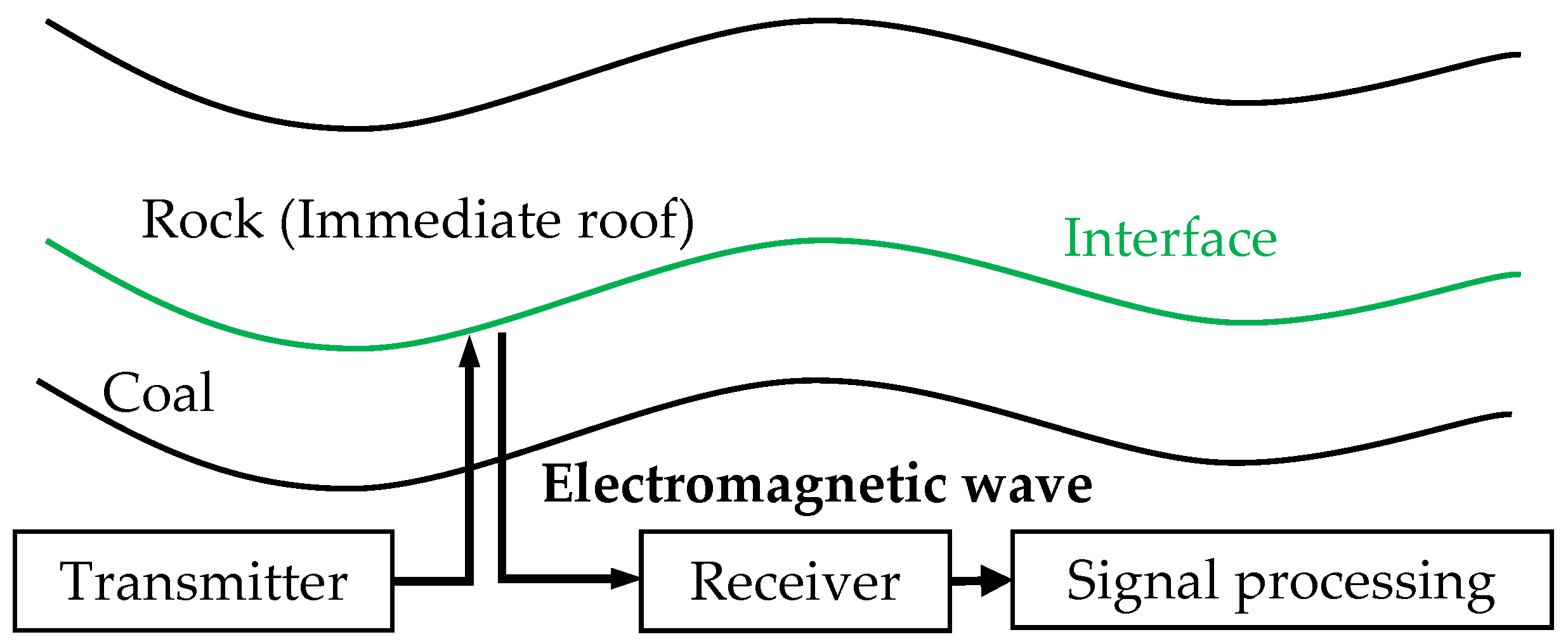
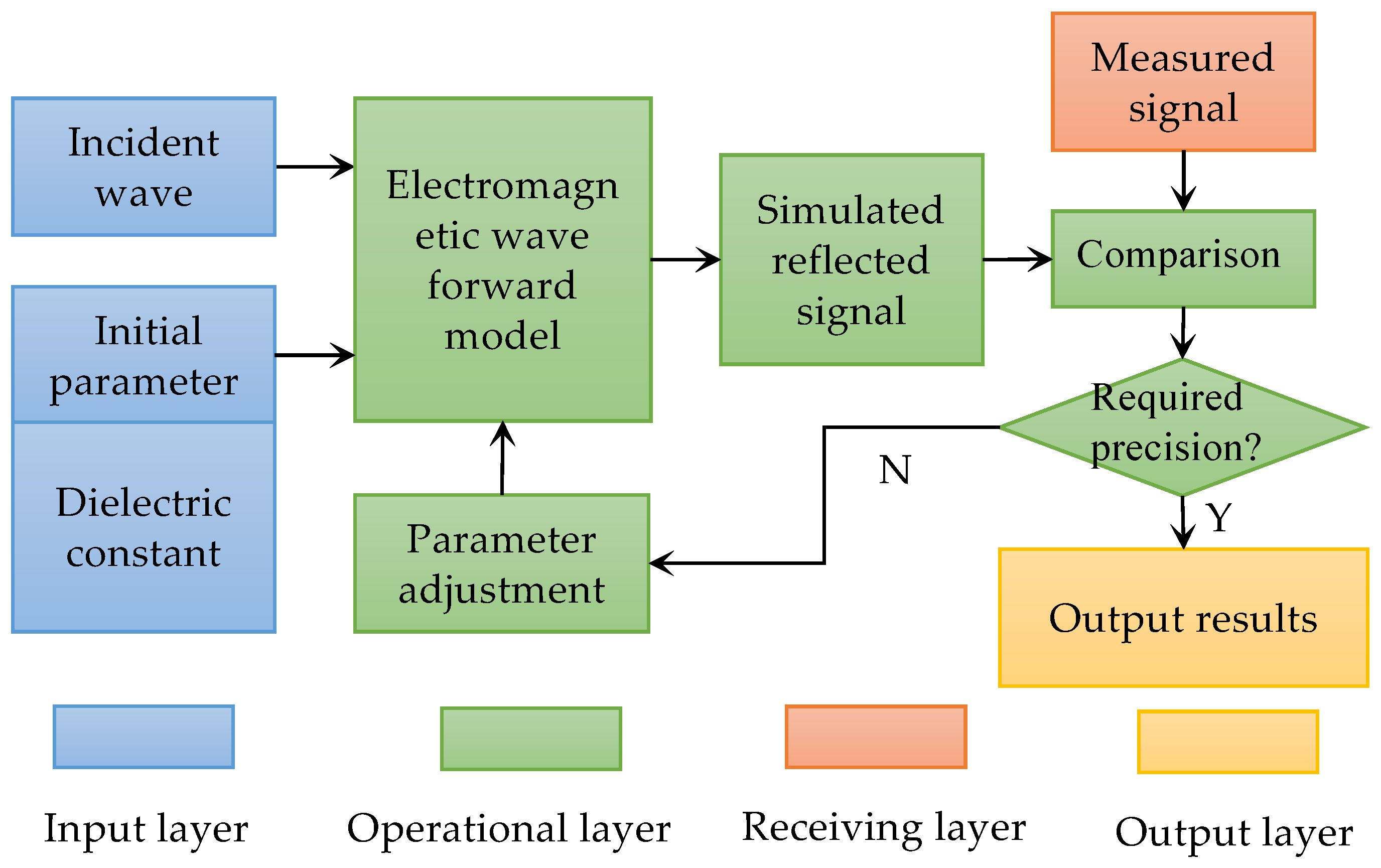
2.1.1. Detection of Top Coal Thickness Based on Ground-Penetrating Radar Technology

A crucial step in enhancing the precision of coal caving control is preemptively detecting and accurately measuring the thickness of the top coal to be caved. In this article, pulse radar ground-penetrating technology is employed based on the disparities in the dielectric constants between coal and rock, enabling the top coal thickness to be detected. Compared to conventional methods using resistivity, low-frequency electromagnetic waves, and seismic waves, the aforementioned method offers several advantages, including high speed, high continuity, high resolution, and low detection costs [26]. The fundamental principle of this method is illustrated in Figure 1.
This figure illustrates successful detection of the top coal thickness through pulse radar ground-penetrating technology by exploiting the discontinuity between the top coal and the immediate roof. A significant alteration in the dielectric constant occurs at this interface due to lithological variations, resulting in an augmented reflection coefficient Γ of the pulsed electromagnetic wave, as depicted in Equation (1):
Γ = ε 2 ε 1 ε 2 + ε 1 .
The velocity of the pulse electromagnetic wave v when it reaches the interface between the coal and rock determines the echo time t and top coal thickness htop (reflection layer height). Therefore, the top coal thickness can be calculated based on this relationship:
h top = t v 2 .
Accurately selecting the radar frequency in pulse radar ground-penetrating technology is the fundamental basis for ensuring correct detection depth and precision. The pulsed electromagnetic waves of the radar offer enhanced penetration and a greater detection depth, albeit with reduced accuracy, during operation at a lower frequency. Conversely, the pulsed electromagnetic waves of the radar provide limited penetration and a shallower detection depth during operation at a higher frequency but offer improved accuracy. Ground-penetrating radar in the LTCC mining faces primarily interacts with media such as metal, coal, rock, and water. This study adopted a radar frequency range of 0.9–5 GHz to parameterize the reflection characteristics of these media on pulsed electromagnetic wave signals. These parameters are fundamental elements of ultrawideband radar signal processing. Based on the distinctive detection characteristics of coal and rock, this study successfully differentiates between coal seams and rock layers while accurately calculating the thickness of coal seams by analyzing and establishing a standardized two-dimensional coal–rock identification chart (Figure 2).

2.1.2. Inertial Navigation Positioning Technology for the Shearer

The inertial navigation system, which ensures seamless operation and provides real-time precise positioning, is crucial in the shearer and serves as the fundamental basis for determining the need to implement hydraulic support actions in automated coal caving control [15]. The mutual positional relationship between the shearer and hydraulic support is determined through real-time positioning. An action command is issued to the hydraulic support when the distance meets the required criteria. This study presents the implementation of high-precision inertial navigation for a shearer utilizing fiber optic gyroscopes and accelerometers with an amplified spontaneous emission (ASE) light source and closed-loop signal processing methodology. The operational principle is based on the Sagnac effect of light. One beam emitted by the ASE light source is split into two beams using a coupler to maintain the working position of the fiber optic gyroscope near a zero-phase shift. Adjustments in one beam are realized through an electro-optic phase modulator. Considering the coherence with the other beam, the angular velocity change information is acquired through counter-propagating motion within the fiber loop. The electro-optic phase modulator is regulated by converting the detected interference signal intensity into a voltage signal, thus generating a feedback phase shift that is equal in magnitude but opposite in direction to that of a Sagnac phase shift value.
The regular working face inertial navigation system achieves an accuracy of approximately 0.06°, whereas the detection accuracy of the system in the intelligent working face increases to 0.01°. The working face is integrated with the inertial navigation system using bolts and threaded holes by carefully selecting a fixed threaded hole on the body of the shearer, ensuring secure attachment. Cohesion between the shearer and inertial navigation system is established through this integration. Simultaneously, a 24 V power supply and CAN bus are derived from the body of the shearer and connected to provide power to the inertial navigation system and offer real-time position information for the shearer. Following on-site installation, one reciprocating movement of the machine facilitates ground testing of the shearer’s inertial navigation system (Figure 3).
Figure 3 shows the real-time transmission and presentation of data obtained from the inertial navigation system by establishing communication with the upper computer data acquisition software using the inertial navigation system. Eliminating these factors is crucial for mitigating vibrations during coal-cutting processes as such vibrations can lead to substantial measurement errors in the data derived from the inertial navigation system. Relatively accurate curve results can be achieved by employing the Kalman filtering technique for smoothing out curves. Comparative results for the actual test position curve of the coal cutter using a surveying instrument further revealed that the application of Kalman filtering produced a higher degree of alignment with the actual curve than that without Kalman filtering. Noticeable symmetry in the reciprocating motion curve was also observed when examining the complete cycle curve of the coal shearer before and after implementing Kalman filtering. Overall, the proposed approach offers high detection accuracy and precision, effectively fulfilling practical mining requirements.

2.2. Coal Gangue Identification and Support Mechanism Action Monitoring Technology for the Intra-Caving Stage

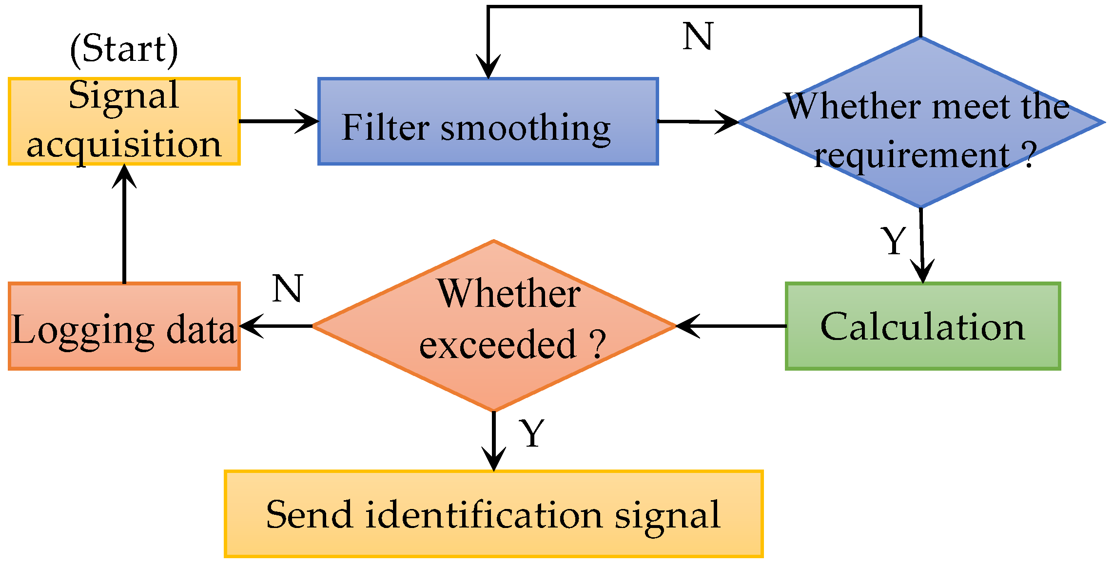
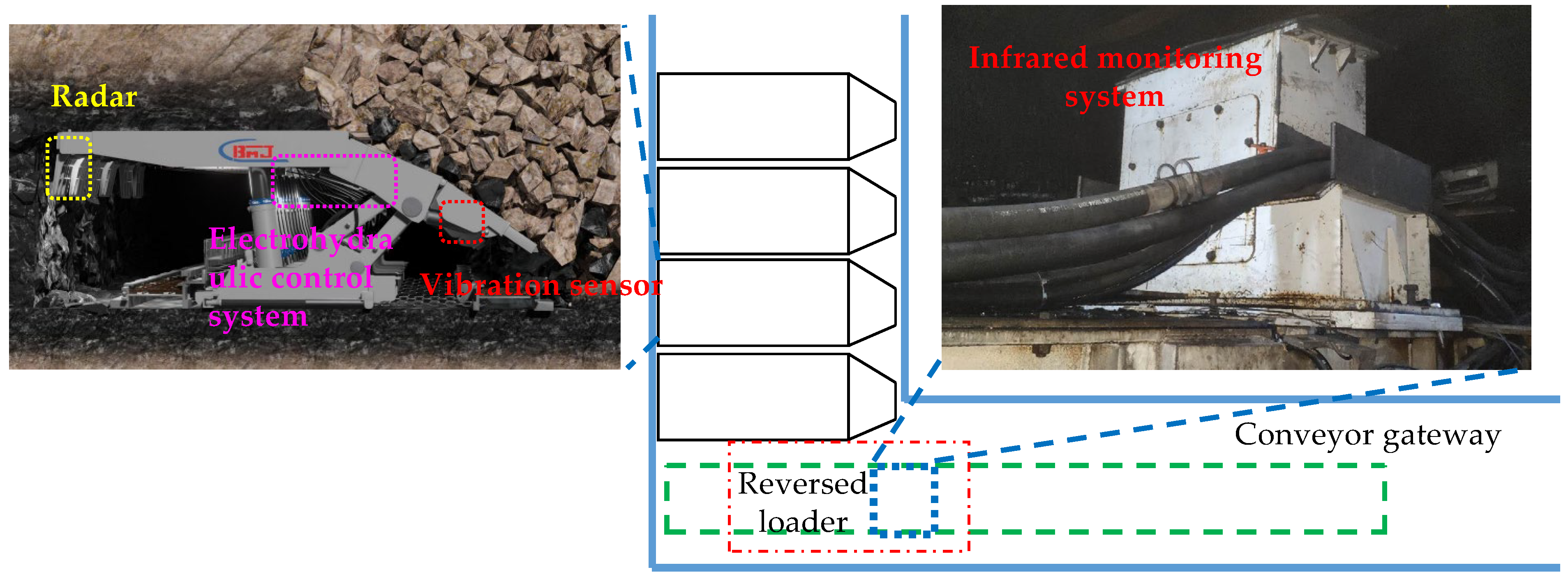
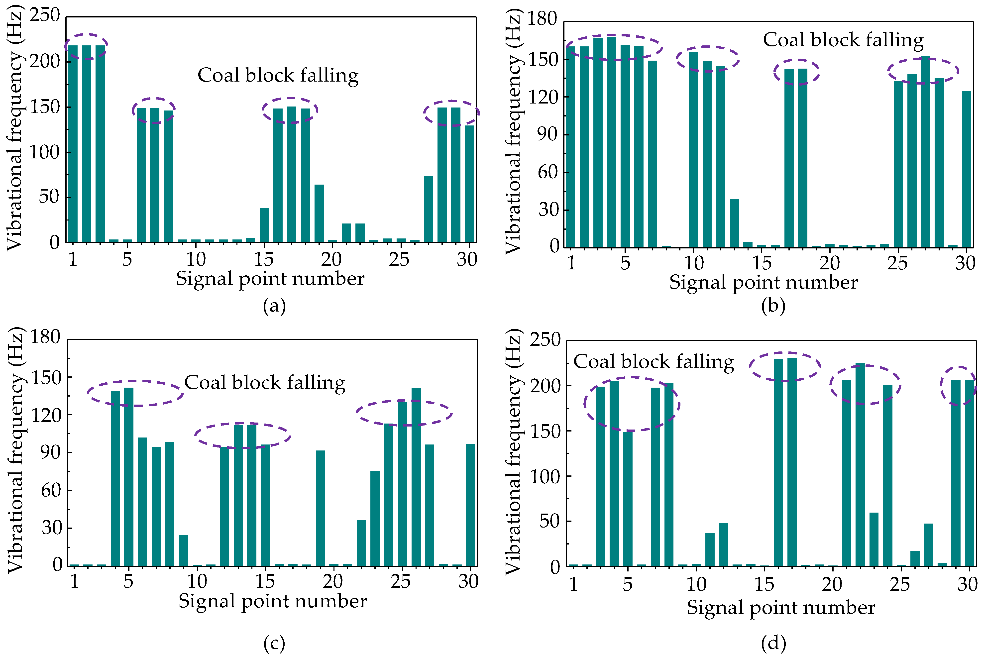
2.2.1. Vibration Sensor-Based Coal Gangue Identification Technology

Efficient and accurate identification technology for coal and gangue is crucial for achieving the automated discrimination of coal cave opening start–stop cycles. A coal and gangue identification processor, which utilizes vibration sensor technology, was specifically developed to automatically control the coal caving process on the LTCC face. Vibration signals such as the amplitude and frequency of the coal gangue are processed using an internal accelerometer module, which filters collected acceleration signals to obtain the vibration frequency. Prioritizing data acquisition, processing, and analysis within the system’s software flow execution ensures overall system operation stability and rationality in the program’s design while enabling real-time data acquisition and processing.
For data acquisition, the vibration sensor initially transmits the collected vibration signals to the peripheral bus of the control system. Subsequently, the Random Access Memory (RAM) unit of the control system temporarily stores these signals using a Direct Memory Access (DMA) controller. In this way, the Central Processing Unit (CPU) can read and analyze the signal. DMA controllers can effectively alleviate the CPU’s workload during signal transmission and enhance their data processing capabilities, ensuring seamless continuity and reliability in system signal processing and data analysis. However, the system does not maintain permanent internal storage of the collected data. Instead, the system temporarily buffers the data for disposal once computations are completed. An internal circular buffer is initialized during system operations to facilitate storage of the collected signals in a first-in, first-out manner. The algorithm processing thread retrieves and processes the data from one end of the buffer while marking the retrieved data blocks [35]. The workflow for data processing and analysis in the system is depicted in Figure 4.
After execution, the program waits for valid data in the buffer (Figure 4). Once available, preliminary processing of the front-end data is performed by the system using a filter before feeding it into corresponding coal gangue recognition models for identification. Threshold comparison based on system settings is conducted after identification is completed, and relevant records are generated. Subsequently, the results are transmitted to a wireless module for external interaction while the program continues to read data and perform the aforementioned calculations. The coal gangue recognition algorithm is crucial in system design because the collected valid data are stored in system RAM and must be read by the internal processing algorithms for model identification to provide accurate coal gangue recognition results.

2.2.2. Precise Monitoring Technology for Support Tail Beam and Insert Plate Travel

The automated top coal caving control in the LTCC face relies on hydraulic support, which initiates the cave opening through insert plate retrieval and tail beam rotation. Therefore, mastering real-time travel data of the tail beam and insert plate as a prerequisite technical guarantee is crucial. Real-time monitoring of the position and posture of these elements can be achieved by installing high-precision and high-reliability travel sensors on the tail beam and insert plate of each support. A comprehensive judgment based on feedback data from pressure, height, infrared, and inclination sensors of the hydraulic support determines whether the position of the tail beam and insert plate meets the necessary requirements. A stroke sensor based on the magnetostrictive principle is employed herein to monitor the piston stroke of the hydraulic cylinder in the tail beam and insert plate of the hydraulic support. Compared with using a dry reed stroke sensor, this measurement process offers enhanced continuity, simplification, and more durable components, as well as significantly improved reliability and stability.

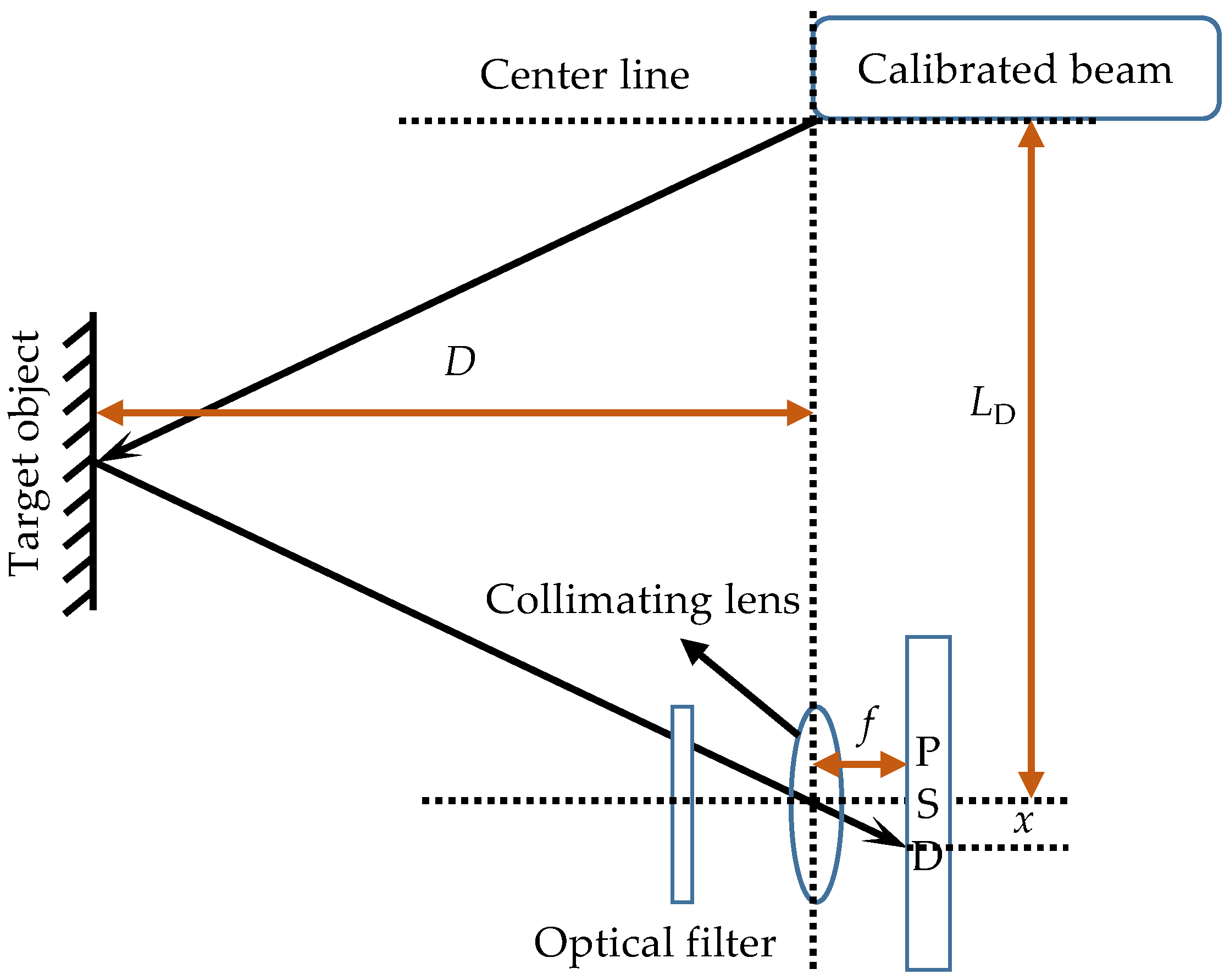
2.3. Real-Time Monitoring of the Top Coal Caving Amount for the Post-Caving Stage

An essential component of automatic coal caving control lies in the real-time monitoring of the top coal caving amount. Following caving, the top coal is conveyed to the rear scraper conveyor, where direct statistical data on the quantity of coal are provided by a real-time monitoring device installed on the conveyor. These data serve as a production report for mine management services and a crucial indicator for feedback regulation, the optimization of coal caving parameters, and automatic control processes.
Infrared scanning ranging technology is employed in this study to perform scanning calculations of the coal quantity in the loader. Specifically, a certain reflection is generated upon refraction onto an object using the principles of the non-diffusive propagation of infrared radiation and extracting information from an infrared light beam. Subsequently, this reflected light beam is captured by an infrared receiving device, and distance values are obtained through calculations. Typical infrared ranging techniques include the phase, triangulation, and time difference methods. Among them, the triangulation method was chosen to carry out measurements in the coal scanning device on the loader due to its measurement principle based on the triangular relationship formed by the transmitting light source, measuring object, and receiver. The applicable measurement range of this device typically falls between several centimeters and several meters. The main components of this device include a calibration beam, collimating lens, and position-sensitive detector (Figure 5).
The measurement process of infrared triangulation ranging is illustrated in Figure 5. The infrared emitter initially emits calibrated infrared rays at a specific angle. Upon encountering the target object, these rays are reflected and subsequently passed through a filter and collimating lens before reaching the photoelectric position detector. The offset x of the light source is detected by the photoelectric position detector during this stage. The principles of geometry inform the following calculation formula for the measured distance D:
D = 1 2 f · L D x .
In practical applications, the initial measurement of the reflection value D1 should be conducted for each point on the conveyor when under a no-load condition. Subsequently, when the conveyor is loaded with a specific amount of coal, the infrared range finder measures a new reflection value at the same point, which is denoted as D1′, and simultaneously identifies the height H of that point. The resulting change in width due to deflection in the infrared angle is represented as Δx. Assuming an infinitesimal angle, distance can be approximated as a straight line, and the following formula can be used to calculate the area:
Δ S ( i ) = f x H ( i ) × Δ x ( i ) .
When extended to the entire section, we use
i n S = Δ S i + Δ S i + 1 + Δ S i + 2 + Δ S i + 3 + + Δ S n
The area S of the vertical coal section on the conveyor can be calculated in accordance with Equation (5). Given the consistent running speed of the conveyor, the instantaneous coal quantity on the conveyor can be estimated by considering the coal quantity within a specific section and the velocity of the conveyor.

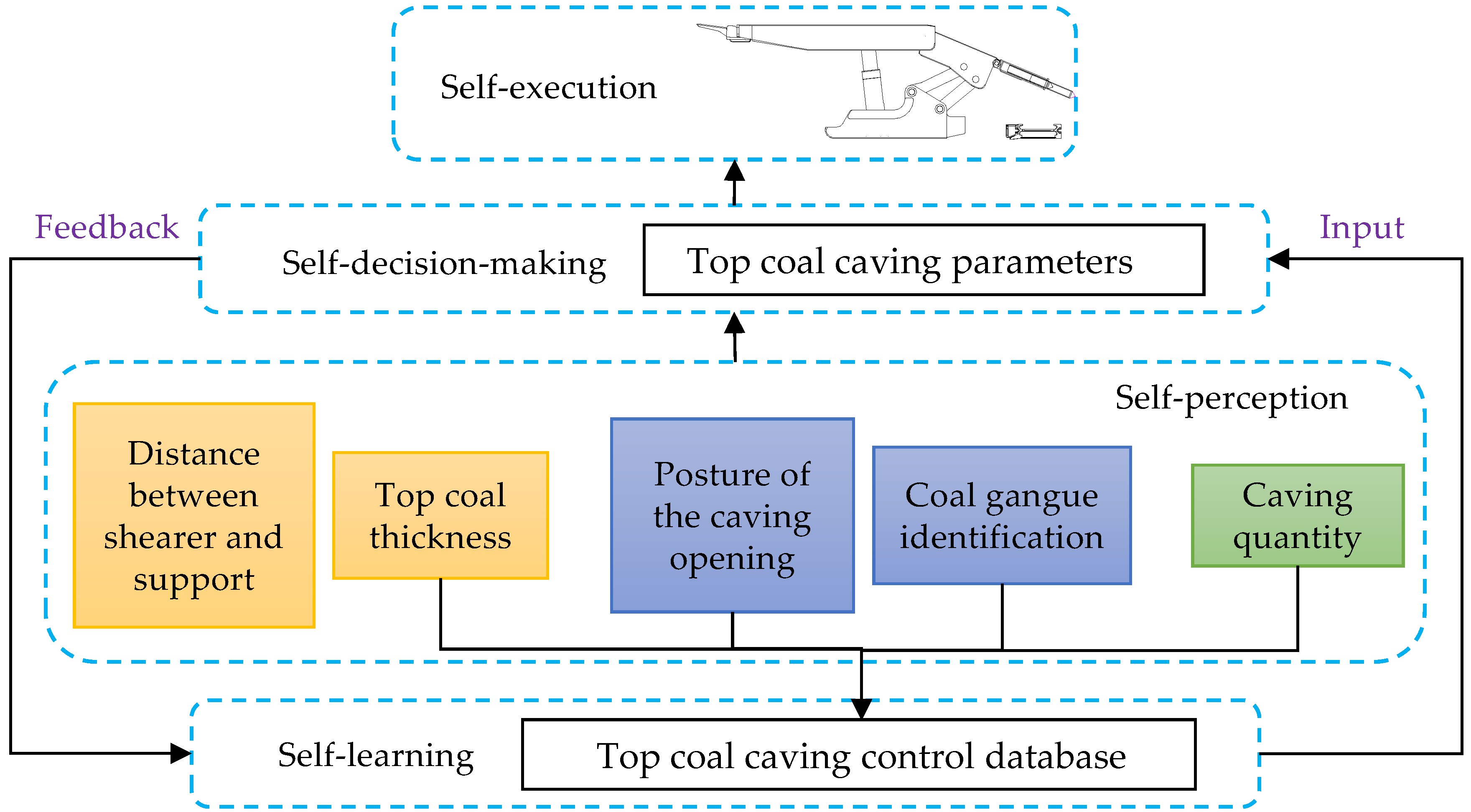
3. Connotation of the Automated Top Coal Caving Control System

An automated coal caving control system for the LTCC mining face was established using the aforementioned technical means. An essential technological prerequisite for realizing automated top coal caving control is integrating the detection and testing methods throughout the pre-, intra-, and post-stages of coal caving into a cohesive technical system that facilitates rapid information acquisition, precise data analysis, and automatic and efficient control. In this system, the ground-penetrating radar is positioned at the leading edge of the hydraulic support frame to measure the thickness of the top coal. The automatic electrohydraulic control system is located beneath the main and shield beams. A coal gangue identification vibration sensor is installed in the lower section of the tail beam, while an infrared real-time coal quantity monitoring system is mounted above the reversed loader. An automated top coal caving control system with self-perception, self-learning, self-decision-making, and self-execution capabilities was thus established using these components. The interconnection among the aforementioned four functions is depicted in Figure 6, while the control logic for automated top coal caving is shown in Figure 7.

3.1. Self-Perception Function

The following five components comprise the self-perception function of the automated top coal caving control:
  • Self-perception of the top coal thickness based on radar detection before top coal caving;
  • Self-perception of the distance between the shearer and support based on inertial navigation before top coal caving;
  • Self-perception of the posture of the tail beam and insert plate during top coal caving utilizing magnetostrictive sensors;
  • Self-perception of the falling gangue during coal caving through vibration sensors for gangue identification;
  • Self-perception of the drawing quantity after coal caving using infrared scanning.
These functions collectively establish the perception layer within an automated top coal caving control system, providing a strong data foundation for subsequent self-learning, decision-making, and execution functions.

3.2. Self-Learning Function

The self-learning function continuously optimizes various parameters during coal caving through deep learning based on monitoring data of the top coal caving volume. This function aims to improve top coal caving and recovery rates by ensuring continuous self-optimization of the automated top coal caving control system. The primary optimization targets include posture optimization of the tail beam and insert plate and identification of the optimal timing for closing the coal cave opening. Implementing self-learning functionality requires the use of a comprehensive database encompassing an extensive array of coal caving data that include fundamental parameters such as the top coal thickness, tail beam retraction angle, coal gangue identification time, delayed cave opening closing time, and associated quantities of the cave’s top coal and recovery rate. The requisite data foundation for effectuating self-decision-making functionality is realized by establishing this system.

3.3. Self-Decision-Making Function

Self-decision-making forms the foundation of the automated coal caving control system, which includes a self-learning function that facilitates the establishment of a comprehensive coal caving database. This database enables parameters such as the top coal thickness obtained through self-perception and the identification time of coal gangue to be compared with existing data, eventually allowing the selection of optimal control parameters such as the tail beam rotation angle and delayed cave opening closing time. Therefore, self-decision-making is an indispensable prerequisite for self-execution.

3.4. Self-Execution Function

Using the coal caving parameters determined via self-decision-making, the self-execution function is responsible for performing corresponding actions through an automated electrohydraulic control system. The self-execution function achieves automatic opening or closing of the coal cave opening by controlling the tail beam and insert plate of the support during the process of automated coal caving control.

4. Application Effects of the Automated Top Coal Caving Control System

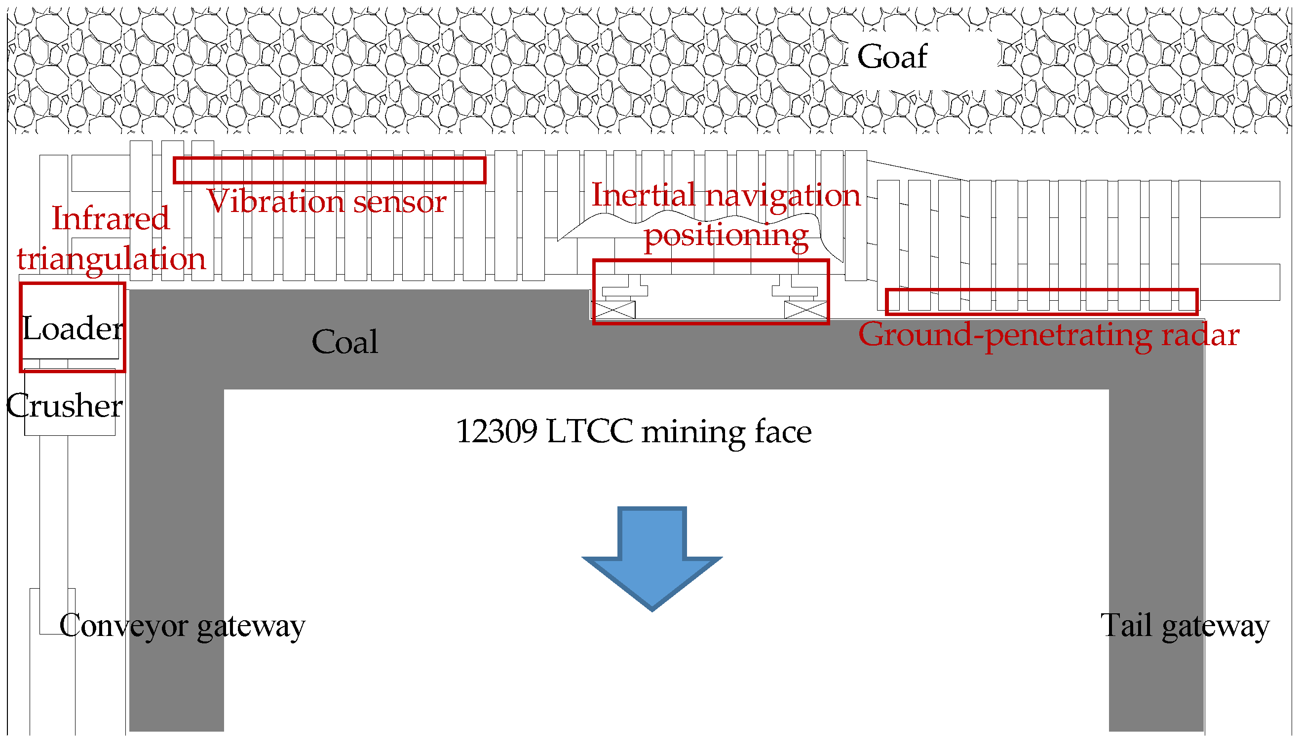
4.1. Engineering Background

Wangjialing Coal Mine is located in Yuncheng City, Shanxi Province, China. The No. 2 coal seam is being extracted on the 12309 LTCC mining face and is characterized by a seam thickness measuring 6.5 m. Specifically, the bottom and top coals have thicknesses of 3.0 and 3.5 m, respectively. Spanning across a length of 260 m, the working face accommodates a total of 148 hydraulic supports, each with a width of 1.75 m. The immediate roof of the working face consists of loose-textured siltstone with an average thickness of 5.4 m. The main roof is composed of hard-textured fine sandstone with an average thickness of 4.2 m. Table 1 lists the lithology and thickness conditions of both the coal seam and the roofs.
Several intelligent modifications were made to the shearer, hydraulic support, and loader to achieve automated coal caving control, including the addition of a high-precision inertial navigation positioning module in the shearer; the installation of a top coal thickness detection ground-penetrating radar on the extension beam of the hydraulic support; the integration of a high-precision electrohydraulic control system and magnetostrictive stroke sensor at the tail beam; the installation of a vibration-based gangue identification sensor below the tail beam; and the placement of an infrared real-time coal quantity monitoring device on the loader. The configuration of the 12309 working face is illustrated in Figure 8.

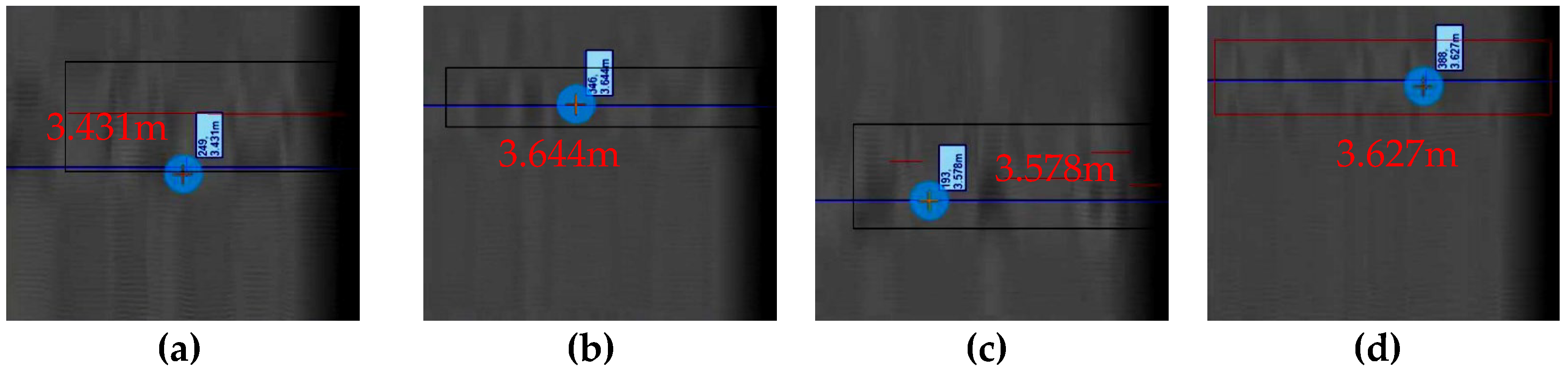
4.2. Application of the Top Coal Thickness Detection Technology

A top coal exploration test was conducted at the 12309 working face of Wangjialing Coal Mine, wherein the radar waveform and grayscale images were initially observed after displacement. The recognition effect under different offsets was examined by adjusting the reference point offset to establish an offset range based on prior experience. Ten hydraulic supports (#16, #66, #81, and #122) were selected to conduct exploratory tests of the top coal thickness. The analytical results of the test data revealed that a small offset yields the maximum characteristic value for the coal–rock interface layer, while a regular moving radar is required to obtain this value in the presence of a large offset. To achieve accurate results, adjustments were made by shifting the radar offset by 5.0 m and placing the antenna approximately 1.5 m below the top coal layer. Systematic up-and-down movements were conducted during testing, followed by grayscale image processing to determine the position of the coal–rock interface. The results obtained from these top coal thickness tests are presented in Figure 9.
This figure reveals that the maximum thickness of top coal measured at the four hydraulic supports is located above support #66, with a magnitude of 3.644 m. The minimum value can be observed above support #16, with a thickness of 3.431 m. The average measured thickness amounts to 3.570 m, resulting in a measurement error of only 2.0% (0.07 m) compared to the mean top coal thickness of 3.5 m, which satisfies the requirements for automated coal caving control.

4.3. Application of Shearer Inertial Navigation Positioning Technology

Controlled reciprocating motion is performed underground within a specific distance to assess the positioning accuracy of the shearer during movement. The shearer traverses between the #125 and #135 supports three times, covering a width of 1.75 m and a one-way length of approximately 17.5 m. The shearer maintains a traveling speed of 4 m/min while an inertial navigation system continuously provides real-time data on the azimuth, sliding, and elevation angles. These data are plotted in Figure 10, where the y-axis represents the inertial navigation azimuth, sliding, and elevation angles, and the x-axis represents the experimental time.
Figure 10 shows that an anomaly in the azimuth angle exists only at the switching point position, while the data at the other positions demonstrate excellent symmetry and relatively high repeatability. Moreover, a strong alignment is observed among the test curves of the azimuth, sliding, and elevation angles, indicating the precise determination of angles by the inertial navigation system at each point during the reciprocating movement of the shearer. Notably, no significant deviation error was observed throughout this reciprocating movement process, indicating a high level of accuracy in system testing.

4.4. Application of Coal Gangue Identification Technology

A vibration sensor is employed during coal caving to enable the real-time detection of gangue caving, thereby providing a decision-making foundation for initiating and terminating actions at the coal cave opening.
To ascertain the vibration signals generated by the vibrating sensor during the coal and gangue caving processes, on-site vibration frequencies were collected for pure coal caving using hydraulic supports #121, #122, #124, and #125, as well as for pure gangue caving processes using hydraulic supports #56, #57, and #58. The data acquired from the vibration sensor of each support underwent filtering and denoising procedures. The testing process was divided into 30 intervals, followed by mean processing to generate histograms for comparative analysis. The distributions of vibration signals during the pure coal and gangue caving processes are depicted in Figure 11 and Figure 12, respectively.
Figure 11 reveals that the vibration frequencies collected by the vibration sensor during pure coal caving remained within a low range. Among all monitoring data from the four hydraulic supports, in support #121, the effective identification data present maximum and minimum values of 128 and 149 Hz, respectively; in support #122, the effective identification data present maximum and minimum values of 168 and 144 Hz, respectively; in support #124, the effective identification data present maximum and minimum values of 142 and 94 Hz, respectively; in support #125, the effective identification data present maximum and minimum values of 231 and 149 Hz, respectively. Overall, the vibration sensor can effectively detect the frequency of coal block caving vibrations. However, while most brackets present minimum and maximum values around 150 and 230 Hz, respectively, the lower range falls slightly below this trend in the test results for bracket 124 (94–142 Hz).
Figure 12 shows that the vibration frequencies collected by the vibration sensor remained consistently high during the gangue caving process. Among all monitoring data from the three hydraulic supports, supports #56, #57, and #58 provide effective identification data ranges of 651–707 Hz, 392–473 Hz, and 304–330 Hz, respectively. These results demonstrate the effectiveness of the vibration sensor in identifying the frequency of vibrations due to falling gangue. After excluding discrete data, a significant increase can be observed within the range of 304–707 Hz compared to that in the range of 150–230 Hz during the pure coal emission process.

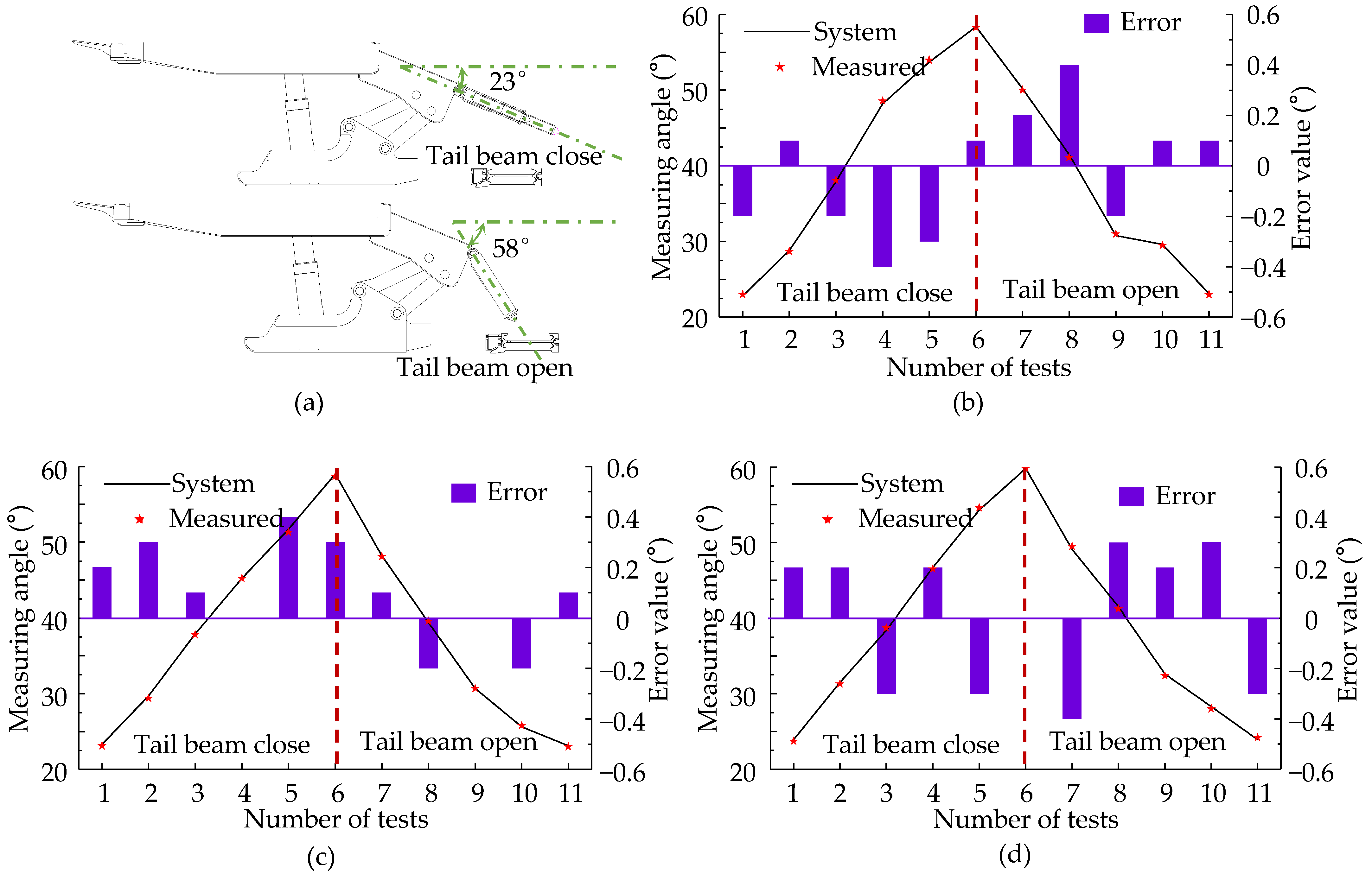
4.5. Application of Tail Beam and Insert Plate Attitude Monitoring Technology

4.5.1. Accuracy Test of the Tail Beam Inclination Sensor

Three supports (#24, #30, and #80) were selected during the ground debugging process of the hydraulic support to evaluate the precision of the tail beam inclination sensor. Eleven measurement points were strategically chosen within one cycle of the tail beam swing, and a high-precision digital inclinometer was employed for manual measurement to accurately record the angle between the tail beam and horizontal line (Figure 13a). A comparative analysis was performed with system-identified data, and the corresponding test results for each support are illustrated in Figure 13b–d.
Figure 13 shows that the inclination sensor for the #24 hydraulic support tail beam has a maximum error of 0.4° within one operational cycle, with a minimum error of 0.1° and an average error of 0.21°. Similarly, for the #30 hydraulic support beam, the maximum error within one operational cycle is 0.4°, with a minimum error of 0° and an average error of 0.17°. A maximum error of 0.4° within one operational cycle can also be observed for the #80 hydraulic support beam, along with a minimum error of 0° and an average deviation measuring approximately 0.25°. The support tail beam inclination sensor presents a measured accuracy of 0.4°, satisfying the requirements for automated top coal caving control.

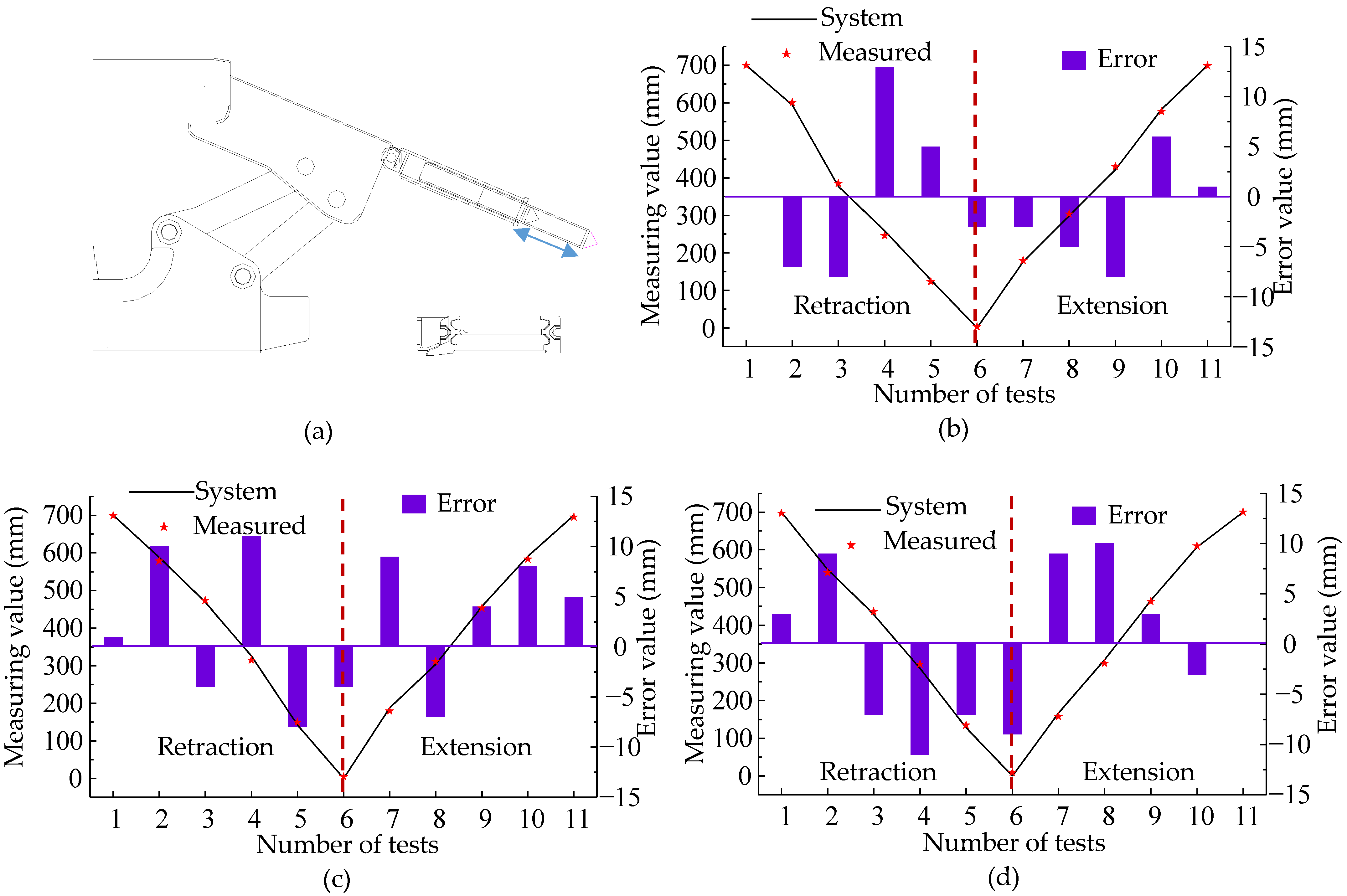
4.5.2. Accuracy Test of Insert Plate Stroke Sensor

Three supports (#14, #72, and #75) were selected during the ground debugging process of the hydraulic support frame to evaluate the accuracy of the stroke sensor for the insert plate. Eleven measurement points were strategically chosen within one complete cycle of plate extension and retraction, and manual measurements using a tape measure were carefully recorded to capture the exposed length of the insert plate (Figure 14a). A comparative analysis was subsequently conducted between these manual measurements and the data identified by the system. The test results for each support are visually presented in Figure 14b–d.
Figure 14 shows that the stroke sensor for the #14 hydraulic support offers a maximum error of 13 mm, a minimum error of 0 mm, and an average error of 5.4 mm within one operating cycle. For hydraulic support #72, the maximum, minimum, and average errors are recorded as 10, 1, and 6.5 mm, respectively, within one operating cycle. Hydraulic support #75 has maximum, minimum, and average errors of 11, 0, and 6.5 mm, respectively, within one operating cycle. The maximum measurement error of the stroke sensor is 13 mm, thereby satisfying the criteria for automated coal caving control.

5. Conclusions

This study focused on the issue of coal caving control in comprehensive mining operations, specifically addressing the following three stages: pre-caving, intra-caving, and post-caving. An automated system for coal caving control was established using various detection and monitoring technologies. This system was implemented at the 12309 working face of Wangjialing Coal Mine, and the effects of key technologies within this system were analyzed through practical measurements. The main conclusions drawn from this analysis are presented below.
  • Integrating ground-penetrating radar, automated electrohydraulic control, vibration signal coal gangue identification, and infrared scanning distance measurement technologies on a computer platform facilitated the development of an automated top coal caving control system with self-perception, self-learning, self-decision-making, and self-execution capabilities.
  • The automated top coal caving control system was tested on-site at the 12309 working face of Wangjialing Coal Mine, encompassing four key technologies: ground-penetrating radar-based top coal thickness detection, inertial navigation-based shearer positioning, tail beam vibration-based identification of coal and gangue, and magnetostrictive sensor-based monitoring of the tail beam and insert plate attitude.
  • In the automated top coal caving control system of Wangjialing Coal Mine, the average error of top coal thickness detection was 2%, the maximum error in the shearer inertial navigation test was 0.01°, the maximum error of the hydraulic support tail beam inclination angle was 0.4°, and the maximum error of the insert plate extension was 13 mm. Overall, these technologies successfully meet the requirements for automated coal caving control when implemented in field conditions.
  • The successful implementation of the automated coal caving control system presented in this article offers a solution for intelligently upgrading LTCC mining faces, providing valuable practical experience for promoting sustainable development within the coal mining industry.

Author Contributions

Conceptualization, Y.H. and D.Z. (Defu Zhu); methodology, Z.W.; software, D.Z. (Dangwei Zhao); validation, Y.H., D.Z. (Defu Zhu) and Z.W.; formal analysis, D.Z. (Dangwei Zhao); investigation, D.Z. (Defu Zhu); resources, D.Z. (Dangwei Zhao); data curation, Z.W.; writing—original draft preparation, Y.H.; writing—review and editing, D.Z. (Defu Zhu); visualization, Y.H.; supervision, D.Z. (Dangwei Zhao); project administration, Z.W.; funding acquisition, Y.H. and D.Z. (Defu Zhu). All authors have read and agreed to the published version of the manuscript.

Funding

This research was funded by the Shanxi Applied Basic Research Programs Science and Technology Foundation for Youths (grant number: 202103021223073); the Key Research and Development Program of Shanxi Province (grant number: 202202090301011); and the Open Research Fund of the State Key Laboratory for Fine Exploration and Intelligent Development of Coal Resources (grant number: SKLCRSM22KF019).

Institutional Review Board Statement

Not applicable.

Informed Consent Statement

Not applicable.

Data Availability Statement

All data and code used or analyzed in this study are available from the corresponding author upon reasonable request.

Conflicts of Interest

Author Yuming Huo was employed by the company Anhui Province Wanbei Coal-Electricity Group Co., Ltd. The remaining authors declare that the research was conducted in the absence of any commercial or financial relationships that could be construed as a potential conflict of interest.

References

  1. Duan, H.; Zhao, L.; Yang, H.; Zhang, Y.; Xia, H. Development of 3D top coal caving angle model for fully mechanized extra-thick coal seam mining. Int. J. Min. Sci. Technol. 2022, 32, 1145–1152. [Google Scholar] [CrossRef]
  2. Shi, J.; Zhang, Q.; Gao, X.; Xue, J. Quantitative Evaluation of Top Coal Caving Methods at the Working Face of Extra-Thick Coal Seams Based on the Random Medium Theory. Adv. Civ. Eng. 2021, 2021, 5528067. [Google Scholar]
  3. Chen, D.; Wu, Y.; Xie, S.; Guo, F.; He, F.; Liu, R. Reasonable location of stopping line in close-distance underlying coal seam and partition support of large cross-section roadway. Int. J. Coal Sci. Technol. 2022, 9, 55. [Google Scholar] [CrossRef]
  4. Klishin, V.; Starodubov, A.; Kramarenko, V.A.; Kadochigova, A.N.; Kaplun, A.V. Analysis of coal outlet parameters by simulation modeling of longwall top coal caving. J. Min. Sci. 2023, 59, 565–571. [Google Scholar] [CrossRef]
  5. Kurlenya, M.; Mirenkov, V. Assessment of deformation of coal seam and longwal lthrough the identification of top coal caving parameters. J. Min. Sci. 2020, 56, 505–511. [Google Scholar] [CrossRef]
  6. Le, T.; Dao, H.; Vu, D. Impact of Discrete Fracture Characteristics on Longwall Top Coal Stability. Acta Montan. Slovaca 2022, 27, 851–863. [Google Scholar]
  7. Chen, D.; Jiang, Z.; Ma, X.; Xie, S.; Wang, E.; Li, H. Evolution law and engineering application on main stress difference for a novel stress relief technology in two ribs on deep coal roadway. J. Cent. South Univ. 2023, 30, 2266–2283. [Google Scholar] [CrossRef]
  8. Liu, Y.; Wang, J.; Yang, S.; Li, L.; Wu, S. Improving the top coal recovery ratio in longwall top coal caving mining using drawing balance analysis. Int. J. Min. Reclam. Environ. 2023, 37, 319–337. [Google Scholar]
  9. Liang, M.; Hu, C.; Yu, R.; Wang, L.; Zhao, B.; Xu, Z. Optimization of the process parameters of fully mechanized top-coal caving in thick-seam coal using BP neural networks. Sustainability 2022, 14, 1340. [Google Scholar] [CrossRef]
  10. Zhang, Q.; Yue, J.; Liu, C.; Feng, C.; Li, H. Study of automated top-coal caving in extra-thick coal seams using the continuum-discontinuum element method. Int. J. Rock Mech. Min. Sci. 2019, 122, 104033. [Google Scholar] [CrossRef]
  11. Jiang, H.; Song, Q.; Gao, K.; Song, Q.; Zhao, X.G. Rule-based expert system to assess caving output ratio in top coal caving. PLoS ONE 2020, 15, e0238138. [Google Scholar] [CrossRef]
  12. Wang, G.; Ren, H.; Zhao, G.; Zhang, D.; Wen, Z.; Meng, L.; Gong, S. Research and practice of intelligent coal mine technology systems in China. Int. J. Coal Sci. Technol. 2022, 9, 24. [Google Scholar] [CrossRef]
  13. Liu, C.; Li, H. Numerical simulation of realistic top coal caving intervals under different top coal thicknesses in longwall top coal caving working face. Sci. Rep. 2021, 11, 13254. [Google Scholar] [CrossRef]
  14. Chang, Z.; Wang, X.; Qin, D.; Zhang, Y.; Chen, X.; Niu, Z.; Wang, J. Study on a mechanical model of a long cantilever beam structure formed by the fracture of thick partings transversely penetrating a coal-caving ellipsoid and its application. Rock Mech. Rock Eng. 2024, 57, 1153–1169. [Google Scholar] [CrossRef]
  15. Wu, G.; Fang, X.; Zhang, L.; Liang, M.; Lv, J.; Quan, Z. Positioning accuracy of the shearer based on a strapdown inertial navigation system in underground coal mining. Appl. Sci. 2020, 10, 2176. [Google Scholar] [CrossRef]
  16. Zheng, J.; Li, S.; Liu, S.; Fu, Q. Research on the shearer positioning method based on SINS and LiDAR with velocity and absolute position constraints. Remote Sens. 2021, 13, 3708. [Google Scholar] [CrossRef]
  17. Xue, B.; Zhang, Y.; Li, J.; Wang, Y. A review of coal gangue identification research-application to China’s top coal release process. Environ. Sci. Pollut. Res. 2023, 30, 14091–14103. [Google Scholar] [CrossRef]
  18. Si, L.; Xing, F.; Wang, Z.; Tan, C. Electromagnetic wave forward modeling of coal-gangue mixed model in top coal caving mining face. Simulation 2022, 98, 1127–1142. [Google Scholar] [CrossRef]
  19. Hou, T.; Kou, Z.; Wu, J.; Xu, P.; Zhang, B.; Peng, Y. Positioning Control Strategy of Hydraulic Support Pushing System in Fully Mechanized Coal Face. Electronics 2023, 12, 3628. [Google Scholar] [CrossRef]
  20. Lv, H.; Liu, F.; Gao, X.; Zhou, T.; Yuan, X. Influence of loading and unloading of hydraulic support on the caving property of top coal. Steel Compos. Struct. 2023, 48, 103–111. [Google Scholar]
  21. Yang, Y.; Zeng, Q.; Zhang, Q. Analysis of coal gangue recognition capability based on vibration characteristics of the tail beam and experimental study on coal gangue recognition in fully mechanized top coal caving. Int. J. Coal Prep. Util. 2023, 2023, 1–22. [Google Scholar] [CrossRef]
  22. Li, H.; Zhang, Y.; Yang, Y.; Zeng, Q. Performance analysis of coal gangue recognition based on hierarchical filtering and coupled wrapper feature selection method. IEEE Access 2023, 11, 85822–85835. [Google Scholar] [CrossRef]
  23. Wang, Z.; Wang, J.; Yang, S. An ultrasonic-based method for longwall top-coal cavability assessment. Int. J. Rock Mech. Min. Sci. 2018, 112, 209–225. [Google Scholar] [CrossRef]
  24. He, T.; Li, G.; Luo, F.; Li, X. Research on mining-induced stress distribution of extrathick coal seams based on electromagnetic wave ct technology. Adv. Civ. Eng. 2022, 6870207. [Google Scholar] [CrossRef]
  25. Li, Y.; Wang, J.; Chen, Y.; Wang, Z.; Wang, J. Overlying strata movement with ground penetrating radar detection in close-multiple coal seams mining. Int. J. Distrib. Sens. Netw. 2019, 15, 1550147719869852. [Google Scholar] [CrossRef]
  26. Ma, Y.; Shen, J.; Su, B.; Ma, Y.; Sun, Q. Research on ground of penetrating radar in the coal mine detecting: A case study of application in Huaibei coal mine. Elektron. Ir Elektrotech. 2019, 25, 37–42. [Google Scholar] [CrossRef]
  27. Wang, X.; Zhao, D.; Wang, Y. Nondestructive detection of coal–rock interface under mining environment using ground penetrating radar image. Int. J. Pattern Recognit. Artif. Intell. 2023, 37, 2354009. [Google Scholar]
  28. Yu, J.; Wang, X.; Ding, E.; Jing, J. A novel method of on-line coal-rock interface characterization using THz-TDs. IEEE Access 2021, 9, 25898–25910. [Google Scholar]
  29. Zhu, H.; Qu, B.; Liao, Q.; Wang, H.; Wang, J.; Hu, L.; Gao, R. Study on the effects of oxidation temperature and ambient humidity on the terahertz spectroscopy characteristics of lignite. Fuel 2023, 349, 128693. [Google Scholar] [CrossRef]
  30. Miao, S.; Liu, X. Free radical characteristics and classification of coals and rocks using electron spin resonance spectroscopy. J. Appl. Spectrosc. 2019, 86, 345–352. [Google Scholar] [CrossRef]
  31. Zhang, N.; Liu, C. Radiation characteristics of natural gamma-ray from coal and gangue for recognition in top coal caving. Sci. Rep. 2018, 8, 190. [Google Scholar] [CrossRef] [PubMed]
  32. Fu, C.; Lu, F.; Wu, F.; Zhang, G. Hybrid connected attentional lightweight network for gangue intelligent segmentation in top-coal caving face. J. Intell. Fuzzy Syst. 2023, 44, 5033–5044. [Google Scholar] [CrossRef]
  33. Fu, C.; Lu, F.; Zhang, G. Gradient-enhanced waterpixels clustering for coal gangue image segmentation. Int. J. Coal Prep. Util. 2023, 43, 677–690. [Google Scholar] [CrossRef]
  34. Zeng, Q.; Zhu, Y.; Yang, Y.; Li, Z.; Wan, L. Influence of Coal Caving Time and Tail Beam Swing Angle on the Evolution of the Coal Gangue Boundary Line during Top Coal Caving. Shock Vib. 2022, 2022, 9982117. [Google Scholar] [CrossRef]
  35. Zhu, Y.; Zeng, Q.; Wan, L.; Yang, Y.; Li, Z. Vibration response difference of caving mechanism under coal rock impact based on mechanical–hydraulic coupling. Sci. Rep. 2023, 13, 13794. [Google Scholar] [CrossRef] [PubMed]
  36. Chen, X.; Wang, S.; Liu, H.; Yang, J.; Liu, S.; Wang, W. Coal gangue recognition using multichannel auditory spectrogram of hydraulic support sound in convolutional neural network. Meas. Sci. Technol. 2021, 33, 015107. [Google Scholar] [CrossRef]
  37. Liu, C.; Mitri, H.; Li, H. Coal and gangue active identification method using microwave irradiation-infrared detection. Minerals 2022, 12, 951. [Google Scholar] [CrossRef]
  38. Zhang, J.; Wang, F.; Wei, W. Collector-assisted efficient coal/gangue recognition based on liquid intervention in longwall top coal caving. Int. J. Coal Prep. Util. 2023, 43, 2065–2090. [Google Scholar] [CrossRef]
  39. Zhang, J.; Han, X.; Cheng, D. Improving coal/gangue recognition efficiency based on liquid intervention with infrared imager at low emissivity. Measurement 2022, 189, 110445. [Google Scholar] [CrossRef]
Figure 1. Basic principles of ground-penetrating radar.
Sustainability 16 04261 g001
Figure 2. Dielectric constant experiment.
Sustainability 16 04261 g002
Figure 3. Inertial navigation repeatability test. (a) Elevation angle of the inertial navigation system; (b) sliding angle of the inertial navigation system; (c) azimuth angle of the inertial navigation system.
Sustainability 16 04261 g003
Figure 4. Data processing flow chart for the coal–rock identification sensor.
Sustainability 16 04261 g004
Figure 5. Principle of the infrared triangulation method.
Sustainability 16 04261 g005
Figure 6. Automated top coal caving control system.
Sustainability 16 04261 g006
Figure 7. Automated top coal caving control logic.
Sustainability 16 04261 g007
Figure 8. 12309 working face.
Sustainability 16 04261 g008
Figure 9. Test results of the top coal detection radar. (a) Detection results of the top coal thickness above support #16; (b) detection results of the top coal thickness above support #66; (c) detection results of the top coal thickness above support #81; (d) detection results of the top coal thickness above support #122.
Sustainability 16 04261 g009
Figure 10. Inertial navigation angles. (a) Elevation angle of the inertial navigation system; (b) sliding angle of the inertial navigation system; (c) azimuth angle of the inertial navigation system.
Sustainability 16 04261 g010
Figure 11. Vibration signal of coal in the caving process. (a) The test results of support #121; (b) the test results of support #122; (c) the test results of support #124; (d) the test results of support #125.
Sustainability 16 04261 g011
Figure 12. Vibration signal of gangue in the caving process: (a) The test results of support #56; (b) the test results of support #57; (c) the test results of support #58.
Sustainability 16 04261 g012
Figure 13. Angle of hydraulic support tail beam: (a) Testing method; (b) the test results of support #24; (c) the test results of support #30; (d) the test results of support #80.
Sustainability 16 04261 g013
Figure 14. Accuracy test of the plugboard travel sensor: (a) Testing method; (b) the test results of support #14; (c) the test results of support #72; (d) the test results of support #75.
Sustainability 16 04261 g014
Table 1. Coal seam and roof conditions.
NameThickness (m)Lithology
Main roof4.2Fine sandstone
Immediate roof5.4Silt stone
Top coal3.5Coal
Bottom coal3.0
Disclaimer/Publisher’s Note: The statements, opinions and data contained in all publications are solely those of the individual author(s) and contributor(s) and not of MDPI and/or the editor(s). MDPI and/or the editor(s) disclaim responsibility for any injury to people or property resulting from any ideas, methods, instructions or products referred to in the content.

