1. Introduction
The soil–structure interaction (SSI) is crucial in evaluating structural responses. When sitting on a flexible soil bed, a system considering the SSI effect exhibits a larger structural period than the system without SSI consideration. Many studies have investigated the SSI effects on the dynamic performance of structures [
1,
2,
3,
4,
5,
6] and on the structural ductility and strength demand [
7,
8,
9,
10,
11,
12,
13].
The stiffness and dynamic characteristics of soil are highly sensitive to the properties of soil contents and superstructure characteristics. To account for these characteristics, Gazetas [
14] proposed a complex frequency-dependent foundation–soil impedance (FSI) function consisting of both real and imaginary components. The real component indicates the stiffness and inertia of the supporting soil, whereas the imaginary component reflects the radiation and material damping of the foundation–soil impedance system. Since Gazetas’ work, numerous studies have been conducted to address various soil modeling issues, such as the incorporation of embedded, non-circular, non-rigid, or piled foundations [
15,
16,
17].
The frequency-dependent nature of soil often necessitates frequency-domain analyses when formulating the equation of motion for the SFS system. However, this approach can come at the cost of losing the benefits that time-domain analysis offers. Incorporating SSI into standard time-history analysis can be achieved by using a method proposed by Safak [
18], which involves approximating the frequency-dependent FSI function in the time domain using a discrete-time digital filter. This allows for the definition of the relationship between foundation forces and displacements through resultant time-domain finite-difference equations. Gash et al. [
19] later applied this method to solve the multiple-degree-of-freedom (MDOF) motion equation of a shear building supported by a rigid disk foundation and uniform-soil half-space. Another approach was taken by Sung et al. [
20], who used a z-transformed discrete-time infinite impulse response filter as a foundation–soil impedance function. They derived a transfer function between ground displacement and foundation shear, which allowed for the analysis of structural responses using the base force propagating function.
The structural damping mechanism typically results in the dissipation of energy, which can be quantified by the viscous damping ratio. This ratio takes into account all sources of energy dissipation and condenses them into a few basic modal parameters. This approach streamlines the motion equations and provides trustworthy outcomes, making it widely employed in both academic research and practical design applications. To determine radiation damping, the ATC3-06 [
21] and ASCE [
22] standards utilize Veletsos’ technique [
23] for assessing the structural and soil parameters. These standards propose that when evaluating foundation damping, it is important to account for both the radiation damping and soil material damping’s energy dissipation effects.
Among these two damping items, the radiation damping is dependent on the geometry of the foundation–soil contact area, the structural properties, and the soil properties. The soil material damping can be calculated from the stress–strain response in a steady-state cyclic loading using a variety of testing techniques. However, this method is only accurate as the system is in resonance [
24]. In addition, due to the frequency-dependent properties of soil, the soil material damping and radiation damping cannot be directly added into the seismic numerical analysis.
Time integration and motion equation are often used for solving the energy equation of motion. By constructing and solving the energy motion equation, McKevitt et al. [
25] evaluated the input energy, hysteretic energy, and the ratio of the cumulative hysteretic energy to the input energy for both single-degree-of-freedom (SDOF) and MDOF systems subjected to four earthquake records. They concluded that the input energy dissipated by the hysteretic mechanism was approximately the same for all four earthquake records.
Uang et al. [
26] proposed two procedures for computing the earthquake input energy: one procedure was based on the absolute motion, whereas the other was based on the relative motion. Bruneau et al. [
27] believed that the input energy derived from the relative motion method was more sensible than that from the absolute motion method. Hu et al. [
28] calculated the additional equivalent damping ratio of an external damping device through energy equations. That is, the ratio of the energy consumption of inherent damping to that of the added dampers can be obtained under external excitations in the time-history analysis. Unlike the strain energy method, this method can eliminate the effect of the excitation frequency on the additional equivalent damping ratio.
From the literature reviewed above, many studies have investigated SSI’s effects, inelastic structural behaviors, near-fault earthquakes, and energy dissipation considering SSI-related damping sources. However, few papers have been concerned with the following aspects together: (1) the implementation of the SSI effect through a frequency-dependent FSI function; (2) the energy quantities of yielding energy due to structural inelasticity and SSI-related energy; and (3) near-fault ground motions, which induce different structural responses to far-field earthquakes.
In view of this, this study aimed to develop a procedure for evaluating the SSI-related damping effect, through an energy perspective, on the responses of bridge pier structures. This evaluation procedure first constructs a soil–foundation–superstructure (SFS) system by expanding an inelastic SDOF system to include a frequency-dependent SSI model via the discrete-time infinite impulse response filter (IIRF) technique. Then, based on the motion equations of the SSI-based SFS system, the energy equations were formulated to distinguish distinct energy quantities in a quantitative manner, particularly the SSI-related energy. The SSI-related damping ratio (SSIDR) was also introduced herein. An implementation study was conducted not only to demonstrate the proposed evaluation procedure, but also to compare the response variance between distinct input earthquake recordings.
This paper proceeds as follows. In
Section 2, the methodology of the evaluation procedure is developed. The implementation study is in
Section 3. Conclusions are addressed in the last section.
2. Methodology
2.1. Soil–Foundation–Superstructure System
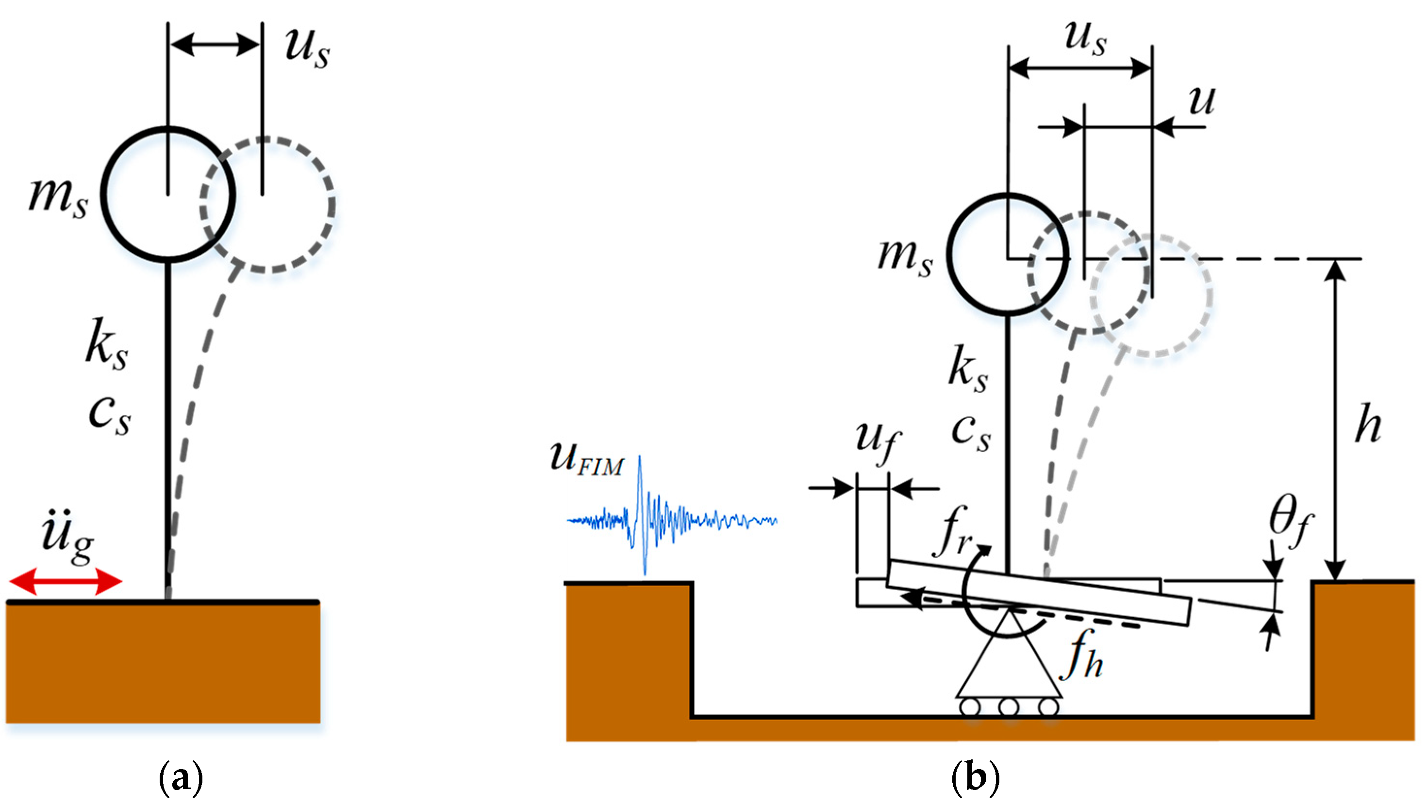
Figure 1a shows an SDOF system sitting on fixed base. The SSI effect is not considered by assuming the fixed-base SDOF system subject to the free-field ground motion. To consider the SSI effect, a 3DOF SSI-based SFS system was constructed by expanding the SDOF system, comprising the underlying soil, foundation, and superstructure, as shown in
Figure 1b. The SFS system includes a set of 3DOF, which encompasses the horizontal displacement
us of the superstructure mass, the horizontal displacement
uFIM, and the rotational angle
θf at the foundation level.
In
Figure 1b,
ms,
cs, and
ks denote the mass, damping, and stiffness of the superstructure, respectively,
us is the mass-to-ground relative displacement, and
uf is the foundation-to-ground relative displacement. The collective soil–foundation dynamic stiffness and damping properties are approximated as the transitional and rotational forces—
fh and
fr—at the foundation level.
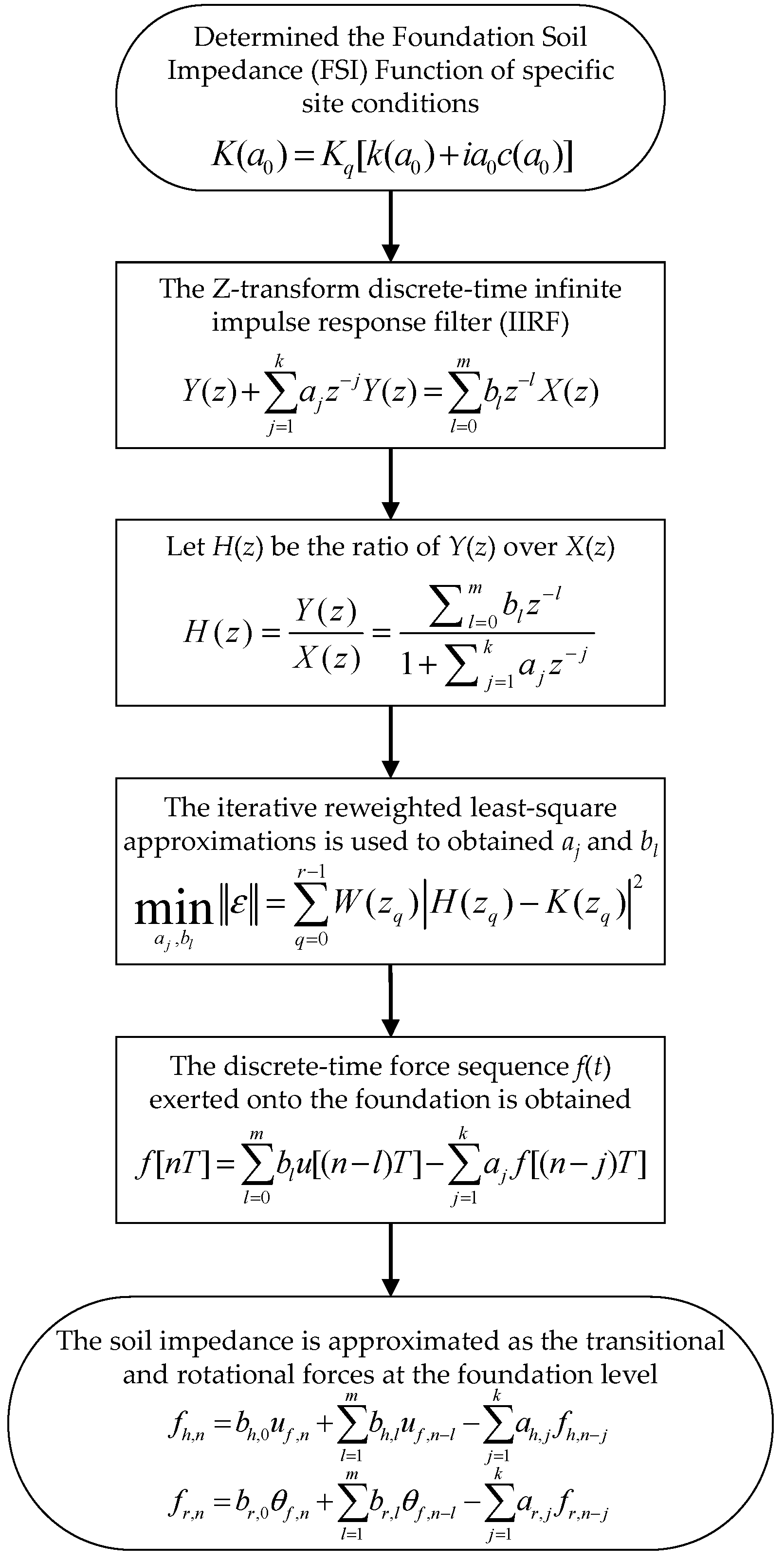
Figure 2 illustrates the process flowchart for determining the transitional and rotational forces using the IIRF technique.
In this context, the method proposed by Veletsos et al. [
16], Sieffert et al. [
24], and Safak [
18] was utilized to calculate the transitional and rotational forces, which are not explicitly discussed for the sake of brevity.
2.2. Motion Equations Considering SSI Effects and Superstructure’s Inelasticity
Equation (1) is used to formulate the equation of motion for the 3DOF SSI-based SFS system at a specific time instance
n.
where
ms = mass of the superstructure
mf = mass of the foundation
If = moment inertia of the foundation
cs = damping of the superstructure
ks = stiffness of the superstructure
The terms , , and , , and , , denote the displacement or rotational angle and their first- and second-order derivatives, and is the ground acceleration. The subscripts s and f represent structure- and foundation-related, respectively.
Equation (1) is intentionally restructured into the format of Equation (2) by relocating the terms
and
to the right-hand side of the equation. The terms
and
, as the partial contents of the horizontal force
fh,n and moment
fr,n, respectively, can be derived from the known quantities
uf,n−1,
θf,n−1,
fh,n−1 and
fr,n−1 of the previous time step. Such practice can avoid recalculation of
and
during the time-wise iteration, thereby enhancing the efficiency of the overall calculation process.
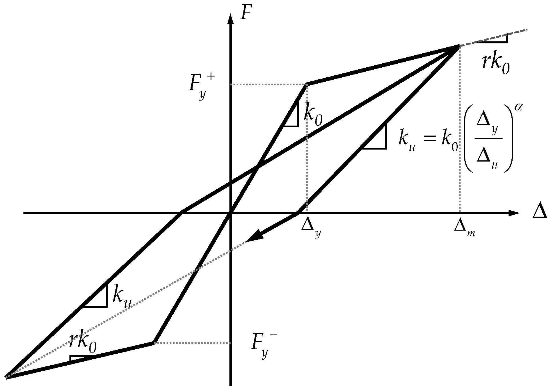
Literally, Equation (2) represents the motion equation obtained under the assumption of a linear system. However, to account for the nonlinear behavior of the superstructure, the Takeda hysteresis model illustrated in
Figure 3 was utilized to depict the force-displacement relationship of the superstructure during cyclic elastic–plastic evolution. The superstructure’s stiffness
ks in Equation (2) is no longer a constant but a variable that changes with the deformation process associated with loading, unloading, and reloading.
Figure 3 demonstrates that this study defines several stiffness components, including the initial stiffness
k0, the post-yielding stiffness factor
r, and power law constant
α.
2.3. Formulation of Energy Equations
To derive the mechanical energy quantities of the defined SSI-based SFS system during a ground motion excitation, Equation (1) is reorganized into the following three equilibrium equations for a particular time instant
t:
Through integration of Equations (5)–(7) w.r.t.
us(
t),
uf(
t), and
θf(
t), respectively, the energy equation for each degree of freedom is obtained:
From the view of energy dissipation mechanism, the above energy quantities can be classified into kinetic energy, Ek(t), damping energy, Ed(t), recoverable strain energy, Es(t), yielding energy, EY(t), SSI-related energy, ESSI-related(t), and input energy, Ein(t), as defined in Equations (11)–(15).
The kinetic energy is associated with the work undertaken by the inertial forces in the components of the system. The recoverable strain energy and yielding energy are dependent on the structural stiffness. The seismic input energy is primarily dissipated through the hysteresis damping of the superstructure and the SSI effect caused by supporting soil, which is alternatively represented through the work undertaken by the transitional and rotational foundation forces in this study.
Based on the energy conservation theorem, the energy equilibrium equation can be written as
2.4. Determination of SSI-Related Damping Ratio
This study used a work–energy theorem equation to determine the SSI-related Damping Ratio (SSIDR), as presented in Equation (17). The SSI-related energy dissipated is equalized with the energy dissipated by an equivalent viscous system during one vibration cycle:
where
ω = circular frequency of excitation
ωn = natural circular frequency of the system
u0 = maximum displacement of the structure in one cycle
ξSSI-related = SSI-related Damping Ratio (SSIDR)
cSSI-related = SSI-related damping coefficient in one loading cycle
In the paper, the frequency-related impedance function is presented in the time domain through the aforementioned IIRF system, and the energy equation expressed by applying the SSIDR is defined in Equation (18). The energy entity
signifies the energy dissipated due to SSI effect during a period of [0,
t].
Meanwhile, the energy dissipated by the inherent damping of the superstructure can be expressed as
where
denotes the inherent damping ratio of the superstructure. Accordingly, the SSIDR can then be defined as
When under an earthquake excitation, the ξSSI-related value varies as the time elapses. To circumvent the needs for determining the energy quantities and ξSSI-related at discrete time instants, this study calculated the ξSSI-related in the form of the total system energy.
3. Implementation Study
A procedure of using the energy method to evaluate the SSI-related damping in a bridge pier system was developed based on the methods and techniques elaborated in
Section 2. This section presents a bridge pier case to demonstrate an implementation procedure.
Theoretically, the proposed SSI-based SFS system is developed by expanding an SDOF model to include the SSI effects (e.g., damping) via the IIRF technique. As the base stone, the accuracy of the fixed-base SDOF model is of great importance.
Therefore, the case study is conducted by first referencing a previous experimental bridge pier study to verify the feasibility of the fixed-base SDOF model, and then conducting seismic analyses on the IIRF-integrated SFS system to explore the SSI effects on the relative displacement responses. Furthermore, great emphasis was laid on the energy dissipation mechanism of the SSI-based SFS system and the role of SSI-related energy dissipating in a quantitative manner (i.e., SSIDR) when different earthquake recordings were considered.
3.1. Experimental Study of Bridge Pier
To illustrate the proposed method and provide a comparison object, an experimental study by Chang et al. [
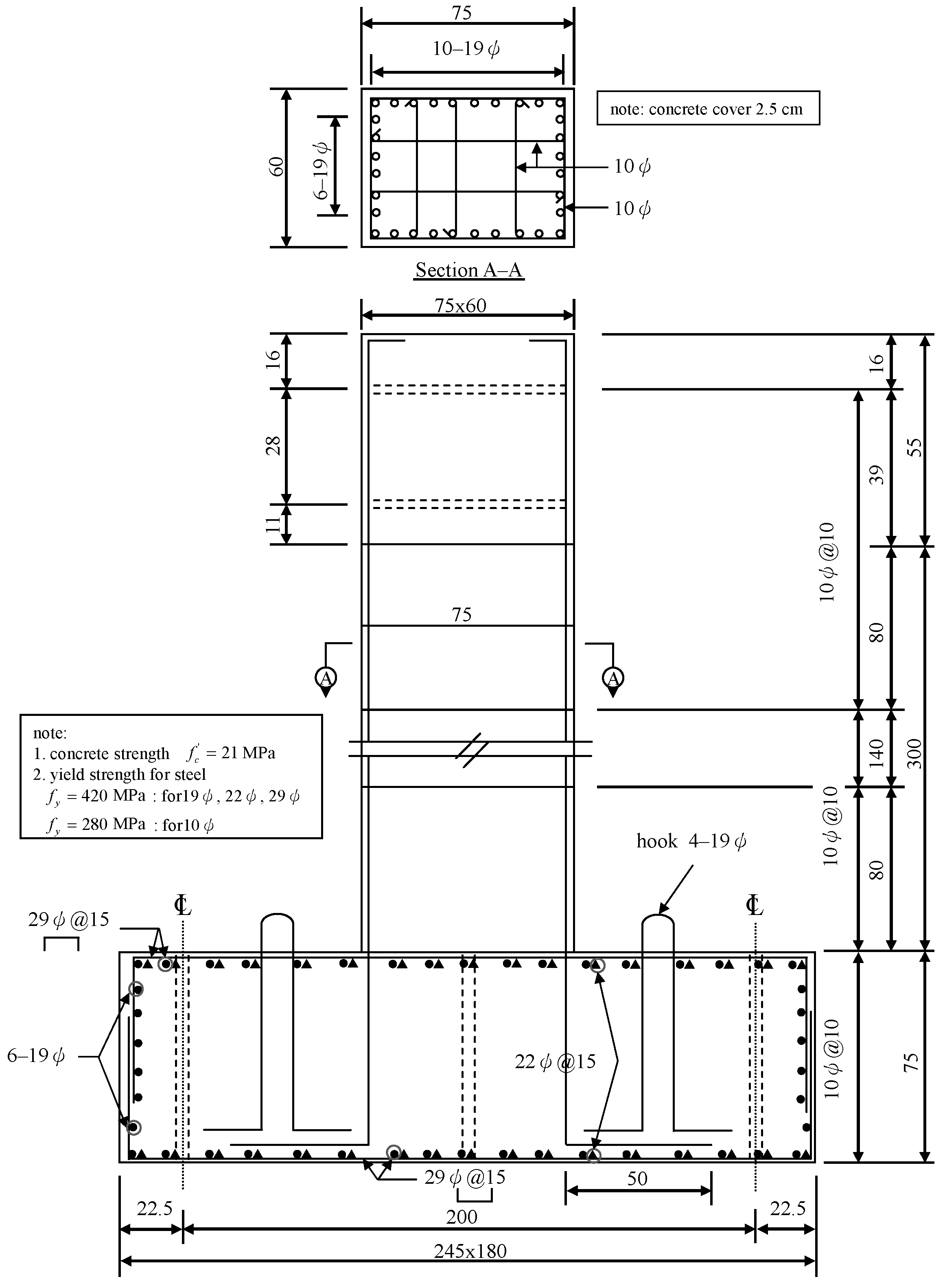
29] was referenced. Chang et al. conducted a series of experimental studies on the hysteresis performance of bridge columns under particular ground excitations. The experimental studies involved three identical reinforced-concrete (RC) bridge piers (Specimens A–C), which were designed according to the 1995 Taiwan Bridge Design Code, and the geometry and reinforcement details of the as-built specimens are illustrated in
Figure 4. The loading conditions were designed so that Specimen A was subjected to a cyclic loading at the specimen’s bottom, and that Specimens B and C were during real earthquake recordings. The masses of 27,500 kg and 68,000 kg were applied via a load cell to Specimens B and C, respectively.
In Chang et al.’s study, the loading conditions of Specimens B and C adopted the ground motion data recorded during the 1999 Chi-Chi Earthquake, Taiwan, at the stations of TCU075 and TCU102.
Figure 5 and
Figure 6 separately display the 30-s ground acceleration and velocity time-histories of the earthquake TCU075 recording with the PGA = 0.8 g and TCU102 recording with the PGA = 0.7 g.
It is noted that both ground excitation records exhibit pulse-like velocity patterns. For example, in the TCU075 ground motion, the ground velocity spikes from nearly zero to its maximum of 280.43 cm/s within a short time duration and then transits to 54.26 cm/s in the opposite direction, and the maximum incremental velocity (MIV) is 334.69 cm/s (+280.43 → −54.26 cm/s). However, TCU102 exhibits a rather opposite fashion in that the velocity instantaneously transits from the upper side peak of 164.34 cm/s to the bottom side peak of 201.99 cm/s, while the MIV is 366.33 cm/s (+164.34 → −201.99 cm/s).
The variance between the TCU075 and TCU102 recordings lay in the fact that the ground velocity from the upper side peak had a large intensity and the bottom side peak had a moderate intensity in the TCU075 recording, i.e., large-to-moderate MIV, and, by contrast, in the TCU102 recording, the ground velocity from the upper side peak had a large intensity to the bottom side peak with a large intensity, i.e., large-to-large MIV.
3.2. Verification of Bridge Pier Fixed-Base SDOF System
According to the results of Specimen A subjected to the cyclic loading, the lateral yielding force
Fy = 411.68 kN with the yielding displacement Δ
y = 42.23 mm, and the ultimate force
Fu = 432.69 kN with the ultimate displacement Δ
u = 150 mm. Based on the results, a Takeda’s model (
Figure 3) can be formulated with
k0 = 9748.78 MPa,
r = 0.06, and
a = 0.5 to present the bridge pier specimens’ elastic–plastic behavior. For the dynamic characteristics of Specimens B and C, the elastic structural period is 0.3337 s and 0.5248 s, respectively.
The fundamental dynamic characteristic of the test can be modeled by an SDOF system using lumped mass and experimental stiffness. A MATLAB-compiled simple fixed-base SDOF bridge pier model that incorporated the derived Takeda’s model was constructed, with the superstructure’s damping ratio of 5%. Dynamic simulations were then conducted by subjecting the inelastic fixed-base SDOF pier model to the earthquake TCU075 and TCU102 recordings (
Figure 5 and
Figure 6).
The resultant restoring force and mass-to-foundation relative displacement are displayed in
Figure 7 and
Figure 8, and the corresponding results of Chang et al.’s study are also depicted for a comparison purpose. According to the results during the earthquake TCU075 recording (large-to-moderate MIV), the maximum lateral restoring force and displacement in the experiment study were 466.97 kN and 68.32 mm, occurring at
t = 14.52 s (
Figure 7), in contrast to the analytical counterpart of 426.86 kN and 68.18 mm.
Likewise, for the earthquake TCU102 recording (large-to-large MIV), the maximum lateral restoring force and displacement in the experiment were 476.78 kN and 60.98 mm at
t = 14.79 s, while the analytical responses, simultaneously, were 429.08 kN and 72.66 mm (
Figure 8). Because pronounced concrete cover spalling and reinforcement buckling occurred at the bottom of the specimen during the test, the test was halted at
t = 16.27 s to avoid unpredictable catastrophes.
Given the resemblance of the hysteresis loops and displacement time-history, as well as the consistency of the maximum lateral restoring force and displacement, it is sensible to deduce that the inelastic fixed-base SDOF bridge pier model is reliable for later use as the foundation for developing the IIRF-integrated SSI-based SFS system.
3.3. Dynamic Analyses of Bridge Pier SFS System
By applying the methods stated in
Section 2.1 and
Section 2.2, the verified inelastic fixed-base SDOF bridge pier model was expanded to include the SSI effect via the discrete-time IIRF technique to develop the target SFS system.
Figure 9 and
Table 1 exhibit the modeling parameters for the soil and the foundation.
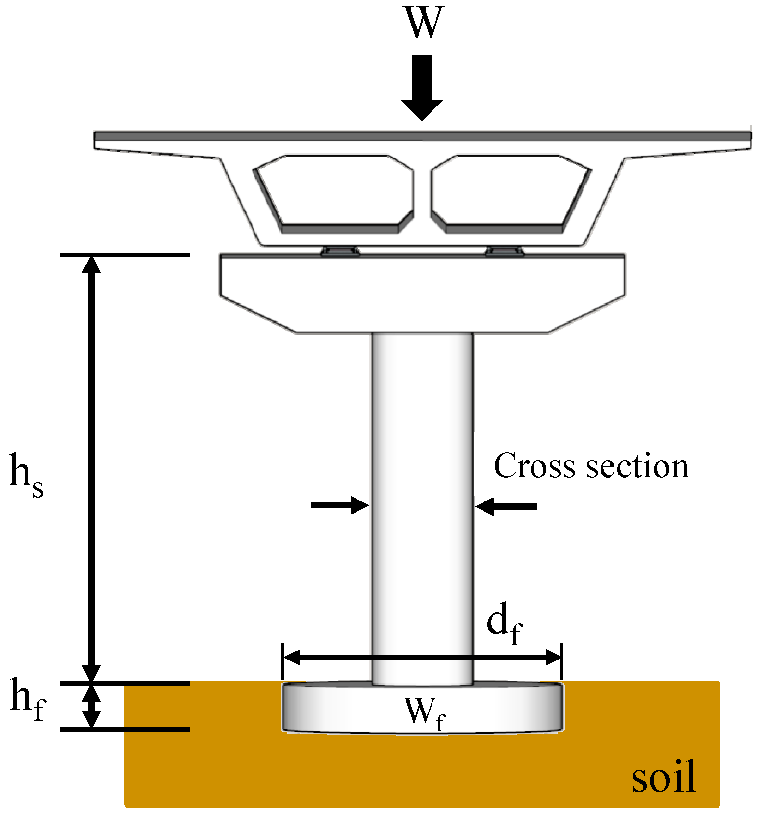
This study employed soil conditions with the shear wave velocity VS = 365 m/s. The superstructure of the SSI-based SFS model was assumed to be supported by a rigid disk foundation and an underlying uniform-soil half-space. The rigid disk foundation is 0.9 m in height and 4 m in diameter, with a mass of 27,143 kg.
Figure 10 and
Figure 11 and
Table 2 present the analytical results of the SSI-based SFS simulation during the earthquake TCU075 or TCU102 recordings, in contrast to those of the corresponding fixed-base SDOF simulation.
From the above results, it was found that:
As to the earthquake TCU075 recording (large-to-moderate MIV), when the SSI effect was considered, the hysteresis loops and the mass-to-foundation relative displacement time-history displayed good resemblance between the SSI-based SFS and fixed-base SDOF systems.
As to the earthquake TCU102 recording (large-to-large MIV), the SSI-based SFS system exhibited wider hysteresis loops and larger superstructure displacement responses than the fixed-base SDOF system. This indicated an amplification effect of the soil on the earthquake excitation and the corresponding superstructure responses.
In this study, frequency domain analysis was conducted on the structural system responses of the Fixed-base SDOF System and SSI-based SFS System using Fourier transform. The influence of the SSI effect on the structural period was investigated during different near-fault ground motions.
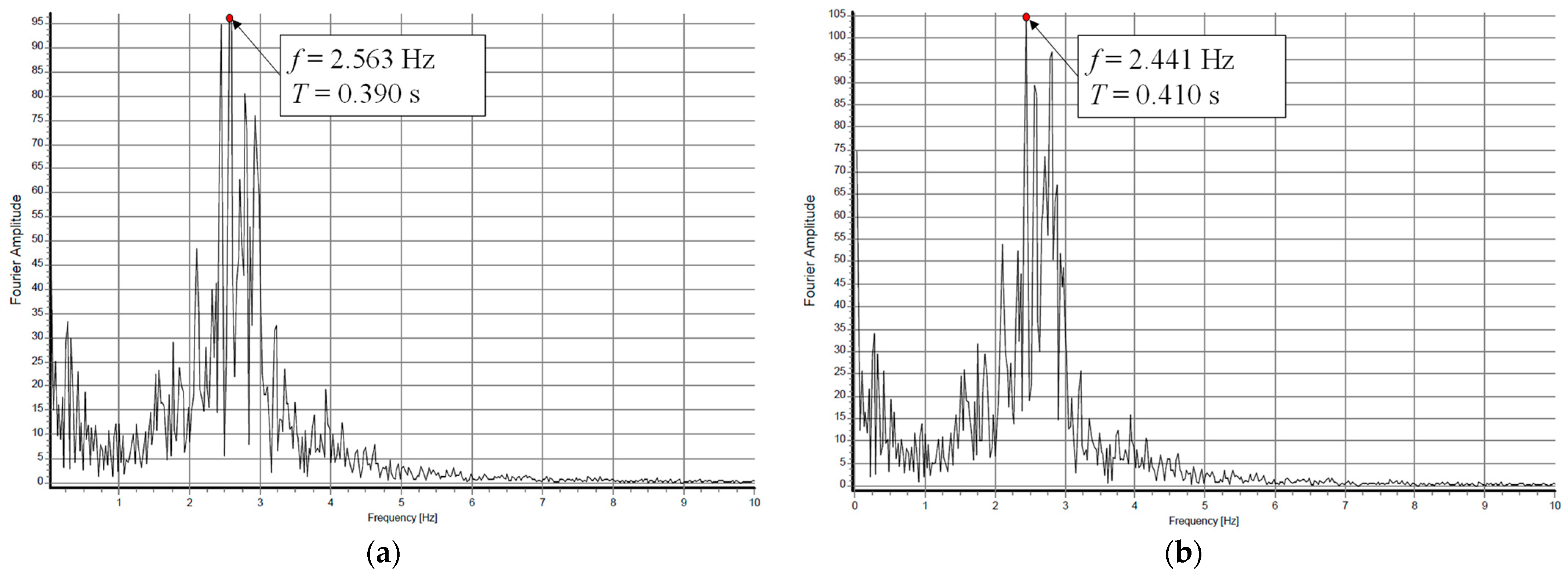
Figure 12 and
Figure 13 show the Fourier spectra of the Fixed-base SDOF System and SSI-based SFS System, respectively, for the earthquake recordings TCU075 and TCU102. The structural periods are summarized in
Table 3. Compared with the elastic period, the structural periods are larger as the structure enters the inelastic phase. Additionally, the results show that considering SSI can prolong the structural period (from 0.390 s to 0.410 s) during the earthquake TCU075 recording (large-to-moderate MIV). Meanwhile, during the earthquake TCU102 recording (large-to-large MIV), there is no difference in the Fourier transform of structural responses between the SFS System and Fixed-base SDOF System (0.640 s). This indicates that the SSI effect is suppressed during the earthquake TCU102 recording (large-to-large MIV).
The above observation exhibits the SSI effects on the displacement response of the superstructure in a qualitative manner, not rending an overview performance of the superstructure, foundation, and soil as a whole. The next section attempts, from an energy viewpoint, to discuss the SSI-based SFS system energy dissipation mechanism and the role of soil in energy dissipation in a quantitative manner.
3.4. Energy Time-History Analysis Considering SSI Effect
According to the formulation of energy equation mentioned in
Section 2.4 and the above analytical results of the SSI-based SFS system subjected to two near-fault earthquake recordings, this study obtained the separate energy quantities of damping energy,
Ed, recoverable strain energy,
Es, yielding energy,
EY, SSI-related energy,
ESSI-related, and input energy,
Ein, as defined in Equations (12)–(15) and shown in
Figure 14 and
Figure 15.
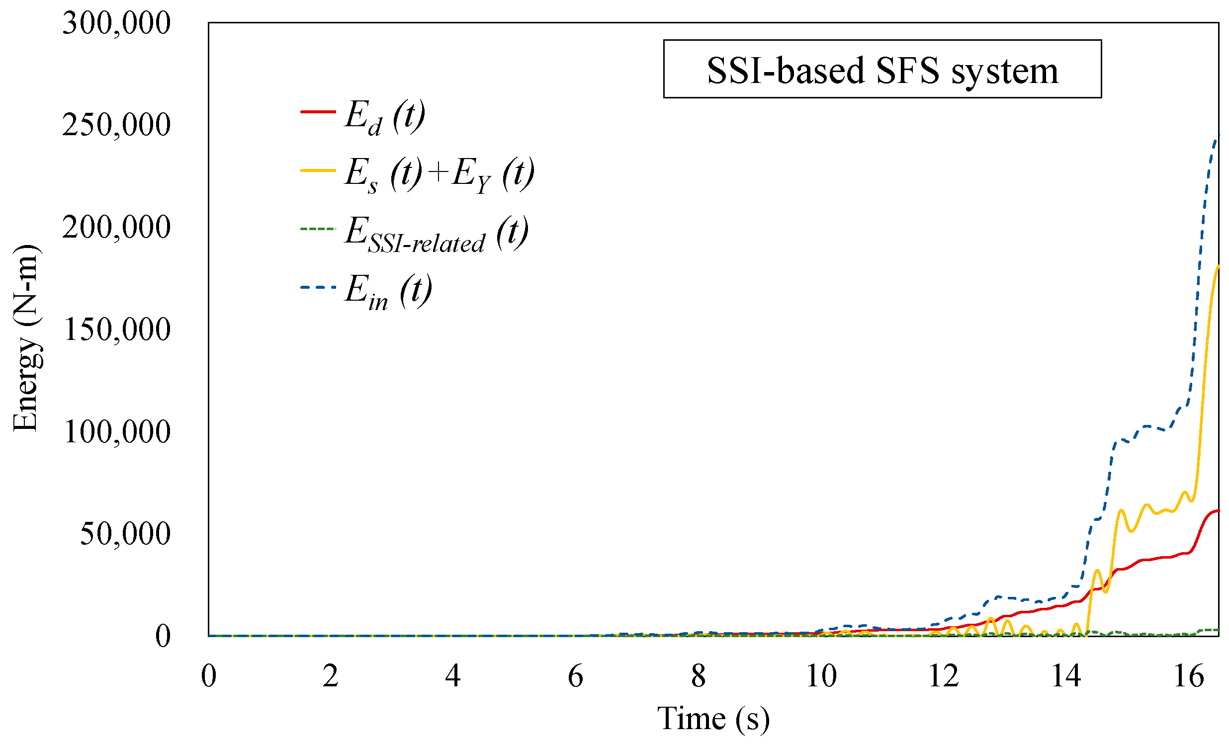
It can be seen from
Figure 14 that as the time elapses from the initiation of the earthquake TCU075 recording (large-to-moderate MIV), the input energy
Ein gradually increases till a considerable leap occurs at
t = 14–15 s. Such leaping fashion simultaneously happens to the energy sum of recoverable strain energy
Es and yielding energy
EY; this indicates that the superstructure enters its inelastic domain concurrently. Notably, the maximum velocity pulse (
Figure 5b) does not coincide with the energy leaping.
Likewise,
Figure 15 gives the energy time history of the SSI-based SFS system during the earthquake TCU102 recording (large-to-large MIV). The maximum velocity pulse occurred at approximately
t = 16 s (
Figure 6b), followed by an excitation cease considering the prevention of possible structural catastrophe, as shown in
Figure 8b. In other words, the original earthquake TCU102 recording was modified by truncating the excitation trace at
t = 16.27 s, after which the ground motion ceased.
In the TCU102 earthquake recording case, no pronounced SSI-related energy dissipation appears (
Figure 15). Such variance may be attributable to the fact that the two earthquake recordings have distinct ground motion traces. As shown in
Figure 6b, TCU102 exhibits a fashion that the velocity instantaneously transits from one side peak to the other side peak, with a velocity change of 366.33 cm/s. Such sudden large-to-large MIV may cause the soil to not be able to react in a short time and the structure suddenly reaches its failure limit.
Table 4 presents the energy quantities integrated over time regarding the earthquake recordings, and the percentage of the total input energy is determined and presented in
Table 4.
According to
Table 4, conclusions can be drawn as follows:
During the earthquake TCU075 recording (large-to-moderate MIV), the SSI-related energy ESSI-related took up only 2.4% of the total earthquake energy, whereas the damping energy Ed and the strain and yielding energy Es + EY accounted for 64.8% and 31.3%, respectively.
During the earthquake TCU102 recording (large-to-large MIV), the velocity pulse shifted too fast to initiate the SSI-related energy dissipation action; therefore, the SSI-related energy percentage was rather small, i.e., ESSI-related = 1.51% Ein. Given the fact that the strain and yielding energy Es + EY = 52.34%, it is sensible to deduce that the superstructure undertook the majority of energy by exerting its inelastic performance, with minor SSI effects on energy consumption.
3.5. SSIDR Determination
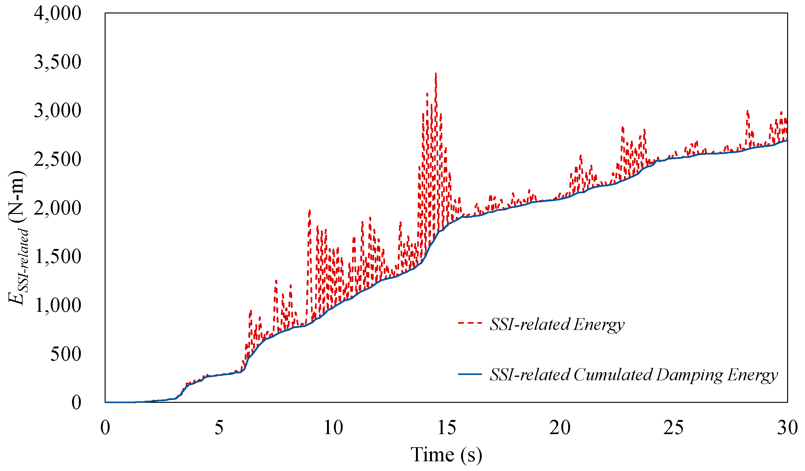
Through the IIRF method, the frequency-dependent characteristics of the soil can be transformed into the time domain for dynamic analysis. As a result, the SSI effect (including the dynamic stiffness and damping property of the soil) were approximated as the transitional force and rotational moment at the foundation level. Therefore, the work done by the transitional force and rotational moment can be regarded as the SSI-related energy of the SSI-based SFS system.
According to the characteristics of cumulated damping and recoverable strain energy, the SSI-related energy illustrated in
Figure 16 can be disassembled into the recoverable strain energy and cumulated damping energy.
Because the SSIDR is a variable during the time-history process, this study used the total system energy to calculate the representative SSIDR during a specific earthquake. The resultant SSIDRs are presented in
Table 5, and a solid trend can be found: The small SSIDR values during the earthquake TCU102 recording (large-to-large MIV) indicated minor SSI effects on the system, and that the majority of the earthquake energy was dissipated through the inelastic performance of the superstructure. This observation is consistent with the findings in
Section 3.3, where the SFS system’s structural period was not prolonged due to the SSI effect during the earthquake TCU102 recording (large-to-large MIV), indicating that the SSI effects are suppressed during near-fault earthquakes with large-to-large MIV characteristics.
4. Conclusions
This study proposed a procedure of using the energy method to evaluate the SSI-related damping effects on the responses of bridge pier structures. Through the IIRF method, the frequency-dependent SSI function was transferred into the time domain to formulate the motion equation of the bridge pier SSI-based SFS inelastic system. Based on the motion equation, the energy dissipation mechanism was formulated to explore the SSI-related and superstructure energy distribution separately. Taketa’s model, with the model parameters calibrated experimentally, was used to account for the elastic–plastic behavior of the bridge pier system. Therefore, the energy consumed by the superstructure yielding can be quantitatively determined. Finally, the SSIDR was obtained from the intrinsic damping ratio and the ratio of the SSI-related energy to the superstructure damping energy. Instead of achieving the SSIDR at each instant, this study determined an overall SSIDR based on the total system energy scale.
Furthermore, an implementation study was conducted based on a previous experimental study to compare the response variance between distinct input earthquake recordings, and the primary findings are briefly summarized as follows:
Earthquakes with large-to-large MIV may lead to low SSIDRs. For those with large-to-large MIV features, considering the decrease in the SSI effect, the structure may be exerted towards more nonlinear behaviors.
Regardless of the earthquake TCU075 or TCU102 recording, the SSI effect was suppressed when the SFS system underwent near-fault earthquakes. This phenomenon illustrated that the stiffness and damping contribution from the soil was not pronounced.








_Xie.png)


