


Theoretical and Experimental Study of Rotational Behaviour of Friction Pendulum Bearings


Abstract
:1. Introduction
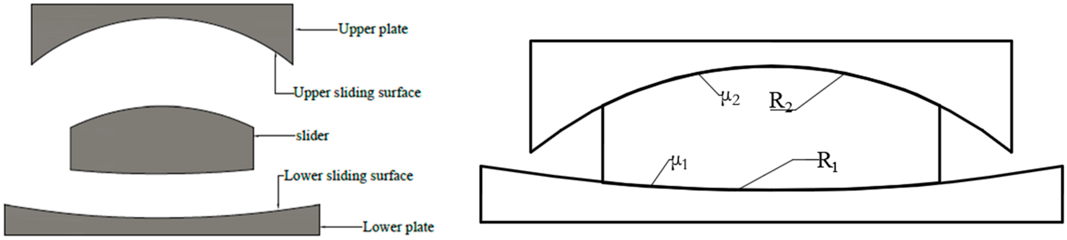
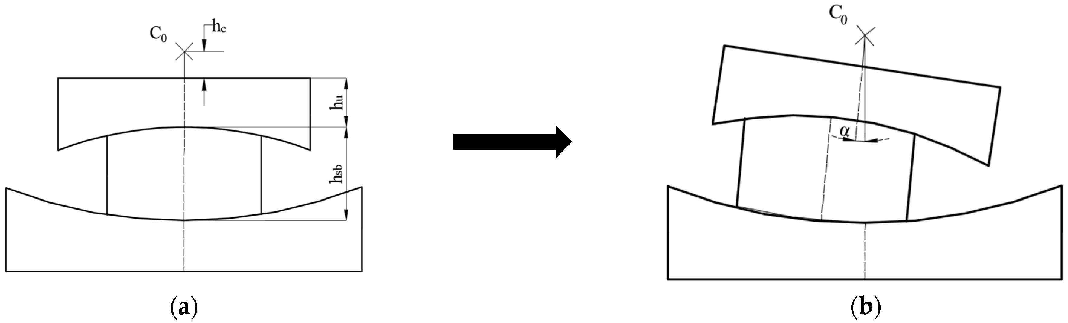
2. Theoretical Study of the Rotational Behaviour of FPB
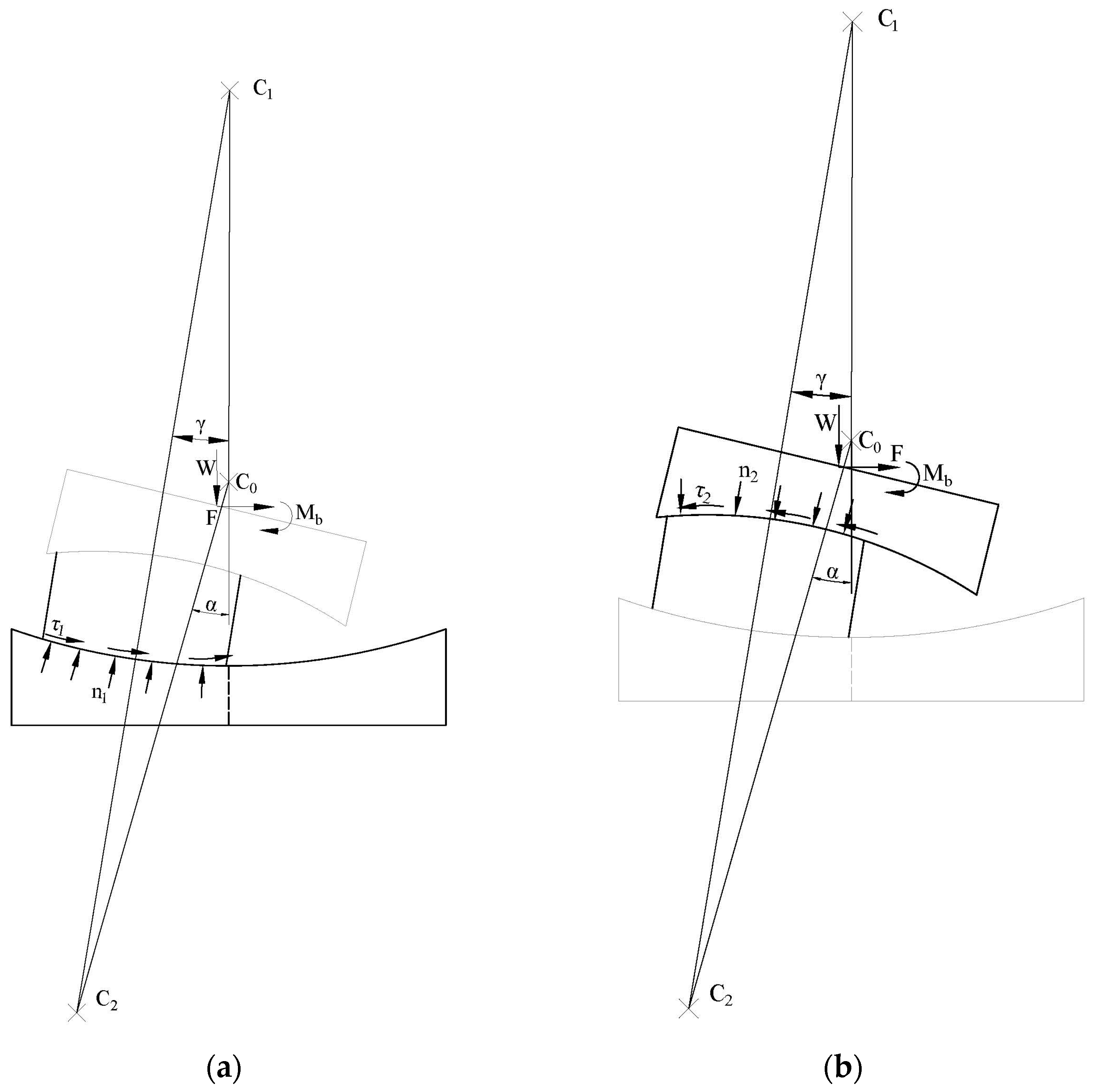
- The vertical load ;
- Rotation moment acting on the upper plate
- The horizontal restoring force ;
- The friction stresses acting on the lower and upper sliding surfaces, respectively and ;
- The normal stresses acting on the lower and upper sliding surfaces, respectively and .
- (1)
- Without any displacement before loading, the horizontal restoring force and moment are linear functions of the rotation angle α. It means that Equations (9) and (10) can be used more conveniently to compute the restoring force and moment of FPB from a zero initial state. It also means that simple connection elements of FEM software can be used to simulate rotational characteristics of FPB bearing.
- (2)
- From Equation (9), the rotational stiffness of the FPB can be obtained by Equation (12). To keep the sign of positive, the condition shown in Equation (13) must be satisfied.
- (3)
- From Equation (9), the values of and are relatively small compared to and , and the sign of is determined by the three first terms of Equation (11), knowing that is inferior to . Therefore, the initial value of the moment of FPB is generally positive. However, if is negative and the FPB rotation angle is large enough, the moment will be negative.
- (4)
- Constant terms of and are only related to bearing parameters and the vertical load; they are independent of the location of the rotation centre. Therefore, the location of the rotation centre has only influence on the rotational stiffness of FPB. To reduce the moment and make the bearing rotate as flexibly as possible, it is suggested to use a smaller friction coefficient and make the difference between the curvature radii of the two concave surfaces as large as possible.
3. Experimental Study
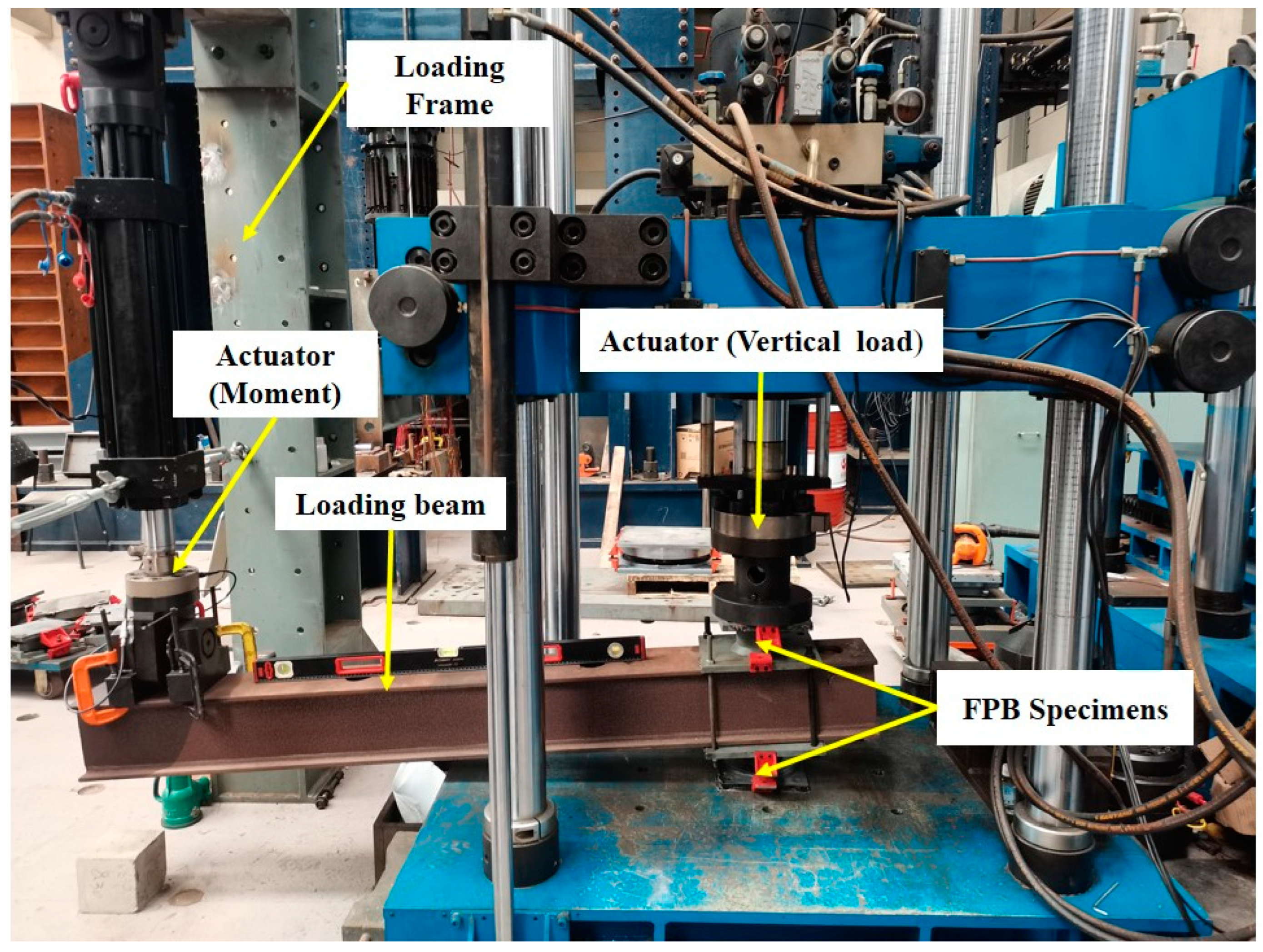
3.1. Testing Device
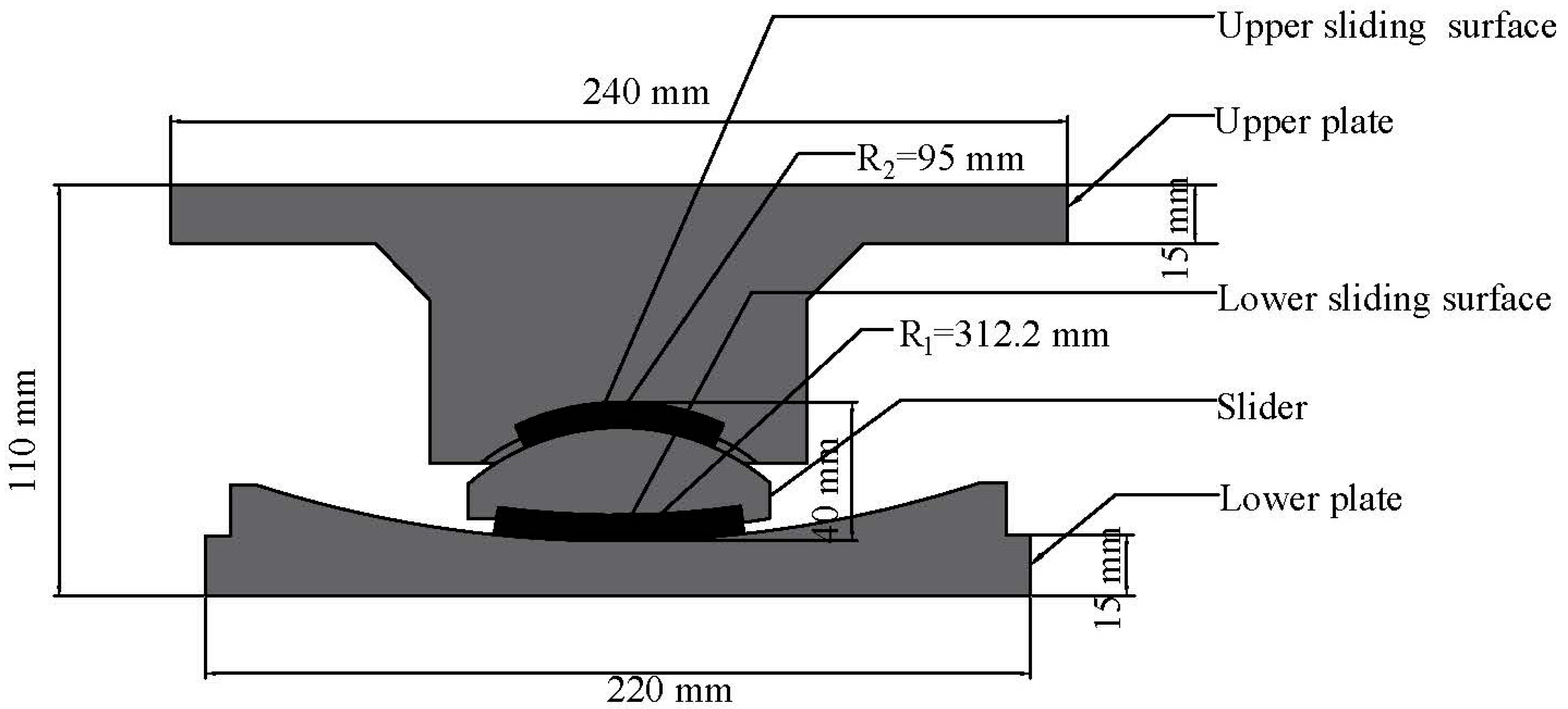
3.2. Test Specimen and Loading Procedure
3.3. Comparison of Theoretical and Experimental Results
4. Conclusions
Author Contributions
Funding
Data Availability Statement
Acknowledgments
Conflicts of Interest
References
- Coburn, A.W.; Spence, R.J.; Pomonis, A. Factors Determining Human Casualty Levels in Earthquakes: Mortality Prediction in Building Collapse. In Proceedings of the Tenth World Conference on Earthquake Engineering; Balkema: Rotterdam, The Netherlands, 1992. [Google Scholar]
- Cao, X.; Shen, D.; Feng, D.; Wang, C.; Qu, Z.; Wu, G. Seismic Retrofitting of Existing Frame Buildings through Externally Attached Sub-Structures: State of the Art Review and Future Perspectives. J. Build. Eng. 2022, 57, 104904. [Google Scholar] [CrossRef]
- Foti, D. Response of Frames Seismically Protected with Passive Systems in Near-Field Areas. Int. J. Struct. Eng. 2014, 5, 326. [Google Scholar] [CrossRef]
- Foti, D. Rolling Devices for Seismic Isolation of Lightweight Structures and Equipment. Design and Realization of a Prototype. Struct. Control Health Monit. 2019, 26, e231. [Google Scholar] [CrossRef]
- Habieb, A.B.; Valente, M.; Milani, G. Effectiveness of Different Base Isolation Systems for Seismic Protection: Numerical Insights into an Existing Masonry Bell Tower. Soil Dyn. Earthq. Eng. 2019, 125, 105752. [Google Scholar] [CrossRef]
- Kim, Y.-S.; Yun, C.-B. Seismic Response Characteristics of Bridges Using Double Concave Friction Pendulum Bearings with Tri-Linear Behavior. Eng. Struct. 2007, 29, 3082–3093. [Google Scholar] [CrossRef]
- Deringöl, A.H.; Güneyisi, E.M. Effect of Friction Pendulum Bearing Properties on Behaviour of Buildings Subjected to Seismic Loads. Soil Dyn. Earthq. Eng. 2019, 125, 105746. [Google Scholar] [CrossRef]
- Imran, I.; Siringoringo, D.M.; Michael, J. Seismic Performance of Reinforced Concrete Buildings with Double Concave Friction Pendulum Base Isolation System: Case Study of Design by Indonesian Code. In Proceedings of the Structures; Elsevier: Amsterdam, The Netherlands, 2021; Volume 34, pp. 462–478. [Google Scholar]
- Scheaua, F. Improvement of Structures Seismic Response Based on Pendulum Systems with Double Sliding Surface. In Proceedings of the IOP Conference Series: Materials Science and Engineering; IOP Publishing: Bristol, UK, 2020; Volume 916, p. 012102. [Google Scholar]
- Ates, S. Investigation of Effectiveness of Double Concave Friction Pendulum Bearings. Comput. Concr. 2012, 9, 195–213. [Google Scholar] [CrossRef]
- Calvi, P.M.; Calvi, G.M. Historical Development of Friction-Based Seismic Isolation Systems. Soil Dyn. Earthq. Eng. 2018, 106, 14–30. [Google Scholar] [CrossRef]
- Avinash, A.R.; Krishnamoorthy, A.; Kamath, K.; Chaithra, M. Sliding Isolation Systems: Historical Review, Modeling Techniques, and the Contemporary Trends. Buildings 2022, 12, 1997. [Google Scholar] [CrossRef]
- Touaillon, J. Improvement in Buildings. Patent No. 99,973, 15 February 1870. [Google Scholar]
- Fenz, D.M.; Constantinou, M.C. Spherical Sliding Isolation Bearings with Adaptive Behavior: Experimental Verification. Earthq. Eng. Struct. Dyn. 2008, 37, 185–205. [Google Scholar] [CrossRef]
- Lu, L.; Lee, T.; Yeh, S. Theory and Experimental Study for Sliding Isolators with Variable Curvature. Earthq. Eng. Struct. Dyn. 2011, 40, 1609–1627. [Google Scholar] [CrossRef]
- Malekzadeh, M.; Taghikhani, T. Adaptive Behavior of Double Concave Friction Pendulum Bearing and Its Advantages over Friction Pendulum Systems. Sci. Iran. 2010, 17, 81–88. [Google Scholar]
- Tsai, C.; Chiang, T.; Chen, B. Experimental Evaluation of Piecewise Exact Solution for Predicting Seismic Responses of Spherical Sliding Type Isolated Structures. Earthq. Eng. Struct. Dyn. 2005, 34, 1027–1046. [Google Scholar] [CrossRef]
- Lomiento, G.; Bonessio, N.; Benzoni, G. Friction Model for Sliding Bearings under Seismic Excitation. J. Earthq. Eng. 2013, 17, 1162–1191. [Google Scholar] [CrossRef]
- Fenz, D.M.; Constantinou, M.C. Behaviour of the Double Concave Friction Pendulum Bearing. Earthq. Eng. Struct. Dyn. 2006, 35, 1403–1424. [Google Scholar] [CrossRef]
- Shang, J.; Tan, P.; Zhang, Y.; Han, J.; Mi, P. Seismic Isolation Design of Structure Using Variable Friction Pendulum Bearings. Soil Dyn. Earthq. Eng. 2021, 148, 106855. [Google Scholar] [CrossRef]
- Ansari, S.; Fallah, N.; Tashakori, J. Optimal Reliability Design of Pure Friction Isolators Using Asymptotic Sampling. Asian J. Civ. Eng. 2019, 20, 911–924. [Google Scholar] [CrossRef]
- Castaldo, P.; Palazzo, B.; Ferrentino, T. Seismic reliability-based ductility demand evaluation for inelastic base-isolated structures with friction pendulum devices. Earthq. Eng. Struct. Dyn. 2017, 46, 1245–1266. [Google Scholar] [CrossRef]
- Becker, T.C.; Mahin, S.A. Effect of Support Rotation on Triple Friction Pendulum Bearing Behavior. Earthq. Eng. Struct. Dyn. 2013, 42, 1731–1748. [Google Scholar] [CrossRef]
- Becker, T.C.; Mahin, S.A. Correct Treatment of Rotation of Sliding Surfaces in a Kinematic Model of the Triple Friction Pendulum Bearing. Earthq. Eng. Struct. Dyn. 2013, 42, 311–317. [Google Scholar] [CrossRef]
- Mosqueda, G.; Whittaker, A.S.; Fenves, G.L.; Mahin, S.A. Experimental and Analytical Studies of the Friction Pendulum System for the Seismic Protection of Simple Bridges; UCB/EERC 2004/01; Earthquake Engineering Research Center, University of California: Berkeley, CA, USA, 2004. [Google Scholar]
- Peng, T.; Yan, B.; Li, F. The Hysteresis Model of the Friction Pendulum Bearing Based on the Moment Balance Theory. Ain Shams Eng. J. 2022, 13, 101707. [Google Scholar] [CrossRef]
- JT-T852-2013; Friction Pendulum Isolation Bearing for Highway Bridges. Ministry of Transportation of the People’s Republic of China: Beijing, China, 2013. (In Chinese)


| Configuration | Vertical Load | Friction Coefficient |
|---|---|---|
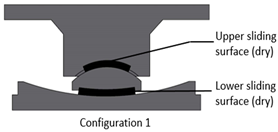 | 20 kN 30 kN 40 kN | |
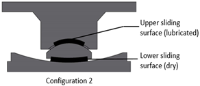 | 20 kN 30 kN 40 kN | |
 | 20 kN 30 kN 40 kN | |
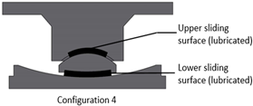 | 20 kN 30 kN 40 kN | |
| Configuration | Vertical Load (kN) | Experimental Rotational Stiffness (kN·m/rad) | Theoretical Rotational Stiffness (kN·m/rad) | Error |
|---|---|---|---|---|
| 1 | 20 | 1.122 | 1.030 | 8% |
| 30 | 1.612 | 1.510 | 6% | |
| 40 | 2.432 | 1.986 | 18% | |
| 2 | 20 | 0.941 | 1.030 | −9% |
| 30 | 1.851 | 1.510 | 18% | |
| 40 | 2.192 | 1.986 | 9% | |
| 3 | 20 | 1.203 | 1.030 | 14% |
| 30 | 1.872 | 1.510 | 19% | |
| 40 | 2.423 | 1.986 | 18% | |
| 4 | 20 | 1.020 | 1.030 | −1% |
| 30 | 1.428 | 1.510 | −6% | |
| 40 | 1.729 | 1.986 | −15% |
Disclaimer/Publisher’s Note: The statements, opinions and data contained in all publications are solely those of the individual author(s) and contributor(s) and not of MDPI and/or the editor(s). MDPI and/or the editor(s) disclaim responsibility for any injury to people or property resulting from any ideas, methods, instructions or products referred to in the content. |
© 2023 by the authors. Licensee MDPI, Basel, Switzerland. This article is an open access article distributed under the terms and conditions of the Creative Commons Attribution (CC BY) license (https://creativecommons.org/licenses/by/4.0/).
Share and Cite
Peng, T.; Liu, Y.; Ka, T.S. Theoretical and Experimental Study of Rotational Behaviour of Friction Pendulum Bearings. Sustainability 2023, 15, 7327. https://doi.org/10.3390/su15097327
Peng T, Liu Y, Ka TS. Theoretical and Experimental Study of Rotational Behaviour of Friction Pendulum Bearings. Sustainability. 2023; 15(9):7327. https://doi.org/10.3390/su15097327
Chicago/Turabian StylePeng, Tianbo, Yuxin Liu, and Thierno Seydou Ka. 2023. "Theoretical and Experimental Study of Rotational Behaviour of Friction Pendulum Bearings" Sustainability 15, no. 9: 7327. https://doi.org/10.3390/su15097327
APA StylePeng, T., Liu, Y., & Ka, T. S. (2023). Theoretical and Experimental Study of Rotational Behaviour of Friction Pendulum Bearings. Sustainability, 15(9), 7327. https://doi.org/10.3390/su15097327