Abstract
With the increasing demand for the energy density of battery system in railway vehicles, the ambient temperature of the battery system is increased. This means that the heat dissipation efficiency and battery service life are reduced, thus reducing the reliability of the battery. Contraposing the problem of the heat dissipation of energy storage batteries, the full deployment of the ARIZ algorithm has been provided for applications of problem-solving processes in this investigation. The advantage of using the ARIZ algorithm is that while the engineering system is kept unchanged or less changed, the effective heat dissipation of the energy storage battery with increasing energy density can be satisfied. During the process of the ARIZ algorithm, a mini problem is first defined. Moreover, the ideal final result and physical contradiction are defined. Following this, expanded material field resources are used, and finally, 22 innovative designs are obtained using the problem-solving tool in TRIZ theory. The final design scheme is provided by combining multiple schemes, and the heat compensator dispersion of a partially improved system in the optimized scheme has been simulated. The results show that the heat compensator dispersion of the air conditioning cooling system for battery modules has reached the design goals in this investigation, in which the maximum temperature of the module’s surface has been reduced to below 35.68 °C, and the maximum temperature difference of the module has reduced to below 5.6 °C.
1. Introduction
With the proposal of China’s “carbon peak, carbon neutral” target, the development of energy saving and emission reduction, together with environmentally friendly rail transit equipment, has become increasingly important for the development of sustainable manufacturing industries. The use of super-capacitors, batteries, hydrogen fuel cells, and other new energy storage power has gradually become one of the major power sources of urban rail transit vehicles [1,2].
However, the energy density of energy storage batteries has been continuously improved with the steady development of energy storage rail vehicles, and problems of battery temperature increase and safety have become increasingly prominent. An energy storage system has high energy density, high power, and high heat generation, and the working temperature of the battery must be within the optimal temperature range to avoid battery overheating, fires, etc. [3]. Meanwhile, when the energy storage power battery is overloaded and overcharged, overheating can easily cause the battery to experience violent chemical reactions, produce a large amount of heat, and may lead to battery leakage, deflation, smoke, fire, and violent combustion resulting in explosions [4]. Therefore, the heat dissipation problem of rail vehicle traction power energy storage has become an urgent problem that needs to be solved for the large-scale application of energy storage power rail vehicles [5].
Reference [6] used a superfluous exhaust from an air conditioner to control the temperature of the super-capacitor energy storage power supply of a tramway, in which the size and position of the exhaust outlet and the design parameter of the flow channel inside the power supply cabinet was optimized. Yang [7] used the computing fluid dynamics method (CFD) to calculate the temperature field of the energy storage power supply. According to calculation results, the optimization scheme of the heat dissipation of the energy storage power supply was proposed, and the optimized scheme was verified so as to provide a reference for the design of energy storage power supplies. Fu et al. [8] presented a systematic review of studies on super-capacitor heat management and compared the traditional heat dissipation and heat conditions of air cooling, liquid cooling, and phase change cooling. They concluded that a single type of cooling device could not meet the heat dissipation requirements of super-capacitors, while the combined comprehensive thermal management system should be considered to solve thermal safety problems in the future. Reference [9] proposed a lumped parameter model of a three-branch liquid cooling system for battery thermal dissipation, and the validation was carried out with the ultrasonic flow sensor test method.
TRIZ (theory of inventive problem solving) can successfully reveal the inherent rules and principles of creation and invention, and it is focused on clarifying and emphasizing contradictions in a system in order to completely solve the contradiction problems of inventions and obtain a final ideal solution. Zhang et al. [9] provided a method for the innovative design of products, and the method is proposed for the functional integration of product innovation based on the laws of need evolution. Shao et al. [10] proposed a mixed information evaluation method that can be developed for screening innovative design solutions, which improves the singularity of the type of solution evaluation indicators after the fusion of QFD and TRIZ. Shao et al. [11] also proposed a method based on the Cynefin framework-aided TRIZ application process to facilitate users using the corresponding design tool in problem-solving. Nie et al. [12] proposed the M-AID process model, which could facilitate the design and development of mechanical and product service system. Shao et al. [13] proposed an integrated method to acquire the technological evolution potential in order to stimulate innovative product designs, and the development of a steel-pipe cutting machine was used to verify its feasibility.
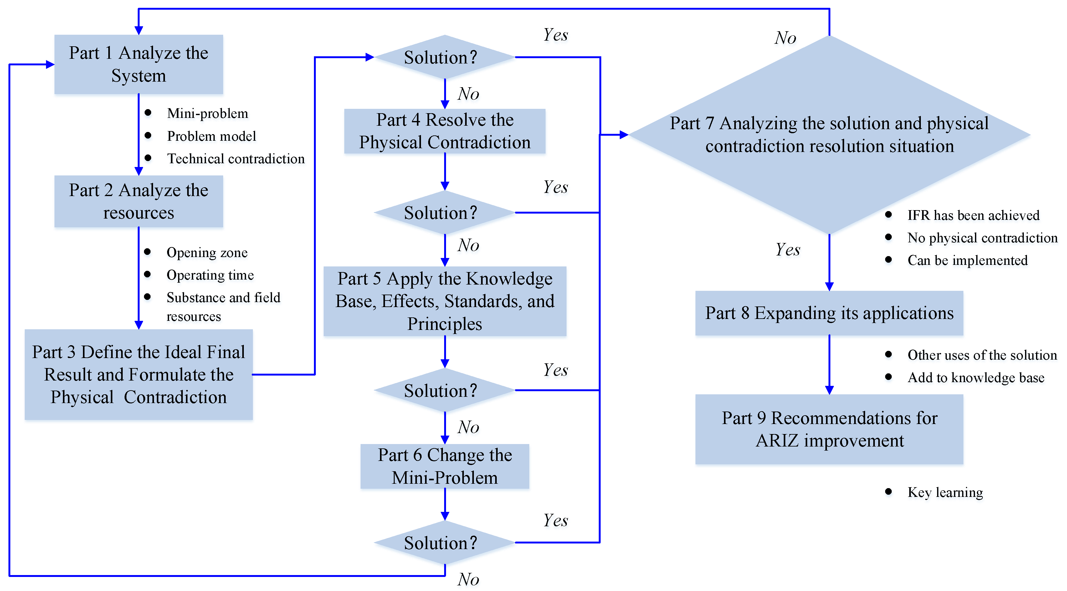
The ARIZ algorithm (algorithm for inventive problem solving) is a useful tool for solving the continuous iterative process problem of the TRIZ theory; this algorithm is a non-computational logical process that involves a series of deformation and redefinition for the initial problem, and it realizes the gradual in-depth analysis and transformation of the problem and finally solves the problem. These two theories are widely used for setting and solving problems to improve the techniques used in engineering system beyond traditional optimization measures. The process of the ARIZ algorithm (ARIZ-85 version) is shown in Figure 1. The solutions for the heat dissipation of energy storage power supplies are considered in order to realize TRIZ, which can provide a scientific and systematic approach to overcome contradictions by using innovative solutions in any field of technology [14,15,16]. The tool for solving the problem of TRIZ, the ARIZ algorithm (algorithm for inventive problem solving) [17,18,19], was adopted. A review of the present literature reveals that only a few works have been devoted to the study and application of ARIZ. Krasnoslobodtsev et al. [20,21,22] solved some problems by using ARIZ. Fey et al. [23] solved some engineering problems by obtaining non-obvious solutions when using ARIZ. Chen et al. used ARIZ as an innovative tool, and it was used for eco-innovation problems [24,25] and patent design problems [26,27].
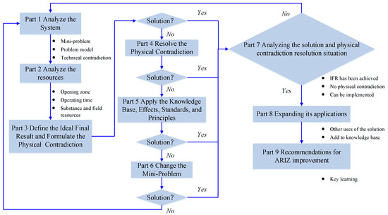
Figure 1.
The application process of ARIZ-85.
In this investigation, the process of the ARIZ algorithm was used to solve the problem of the heat dissipation problem of energy storage power supply in the field of rail transit technology in Section 3, which included a set of TRIZ tools, such as technology contradiction, Su-field model, physical contradiction, the ideal final result (IFR) and method of small smart people that can guide designers to obtain the solutions. Then the schemes were preliminarily evaluated and discussed in Section 4. Finally, the feasibility of the scheme was further verified by simulation.
2. The Description of Problems
2.1. Technical Background
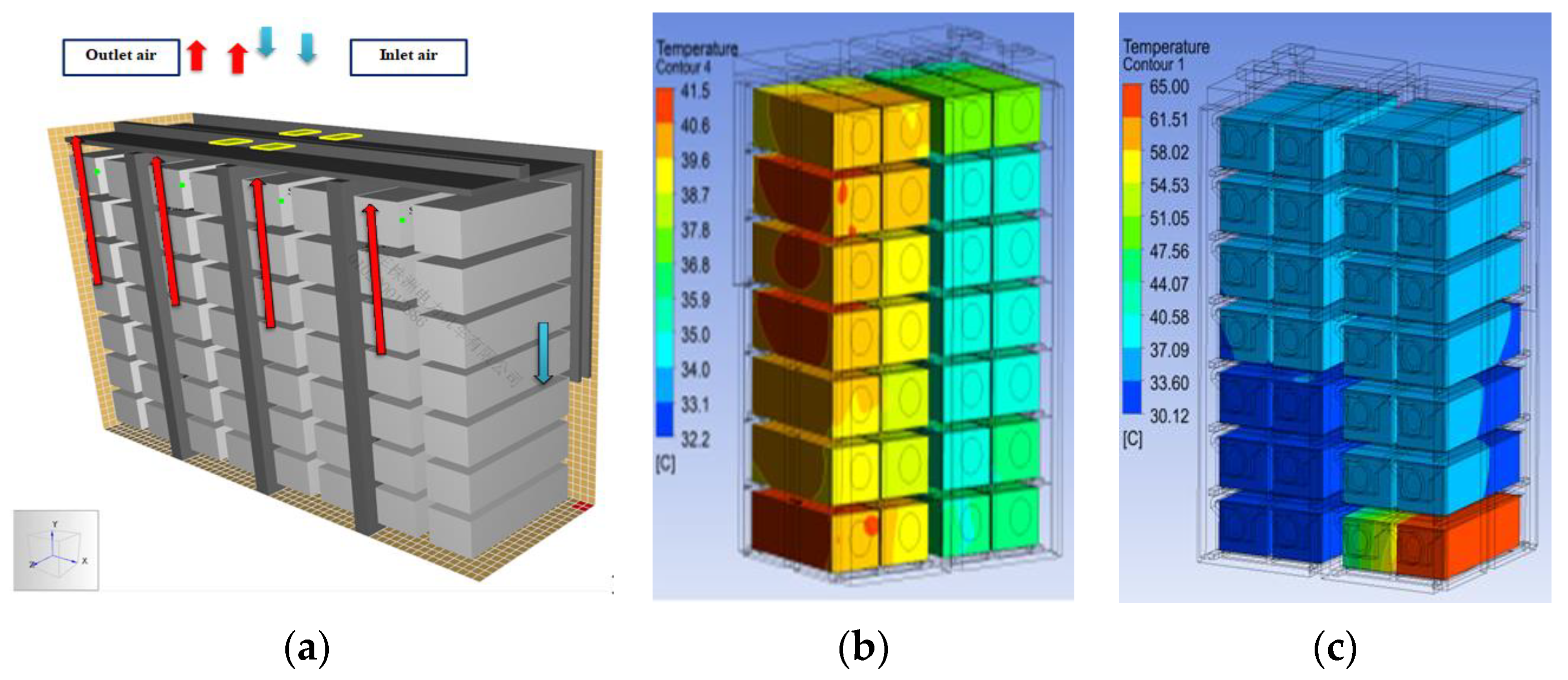
With the increasing demand for energy density in energy storage rail vehicles, battery efficiency, lifetime, and safety has become a primary concern in engineering respect. At present, existing solutions, including natural cooling, forced air cooling, and liquid cooling, both have their disadvantages and applicability. The diagram of the supply air cooling flow channel structure is shown in Figure 2a, in which the temperature distribution of the battery system has been analyzed by simulation in ANSYS fluent. The result clearly shows in Figure 2b that the temperature distribution is uneven, and the maximum temperature of the module inside the battery box is up to 65 °C, as shown in Figure 2c. It is also clearly found that the temperature difference inside the module is relatively large. Moreover, the minimum heat dissipation space between battery modules is around 2 mm for the supply air cooling flow channel, as illustrated in Figure 2a. Therefore, it means that using traditional forced cooling to control the temperature of the energy storage power supply has been very difficult under the limited space and weight conditions of the energy storage power supply.
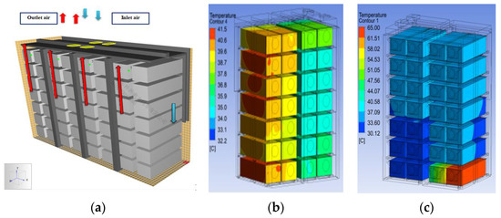
Figure 2.
Temperature distribution of energy storage power supply with single means of forced air cooling. (a) Illustration of supply air cooling flow channel for the battery system; (b) The temperature distribution at battery of the uneven temperature; (c) The temperature distribution at battery of the high temperature.
In this investigation, the ARIZ algorithm is applied to optimize the heat dissipation system of the energy storage battery. Considering the actual technical requirements of the studied system, the goal to be achieved is that the optimal scheme obtained is necessarily ensured that the working temperature of the energy storage system must be reduced to below 38 °C, and the temperature difference between battery modules must be reduced to below 6 °C.
2.2. The Analysis and Description of Problems
The function analysis in TRIZ theory has been used to analyze the key problems. In order to clearly obtain the key problems, it is necessary to clarify the engineering system that was generated, which is the energy storage power supply for the locomotive considered as the system in this investigation. For this system, its main function is blocking the heat field.
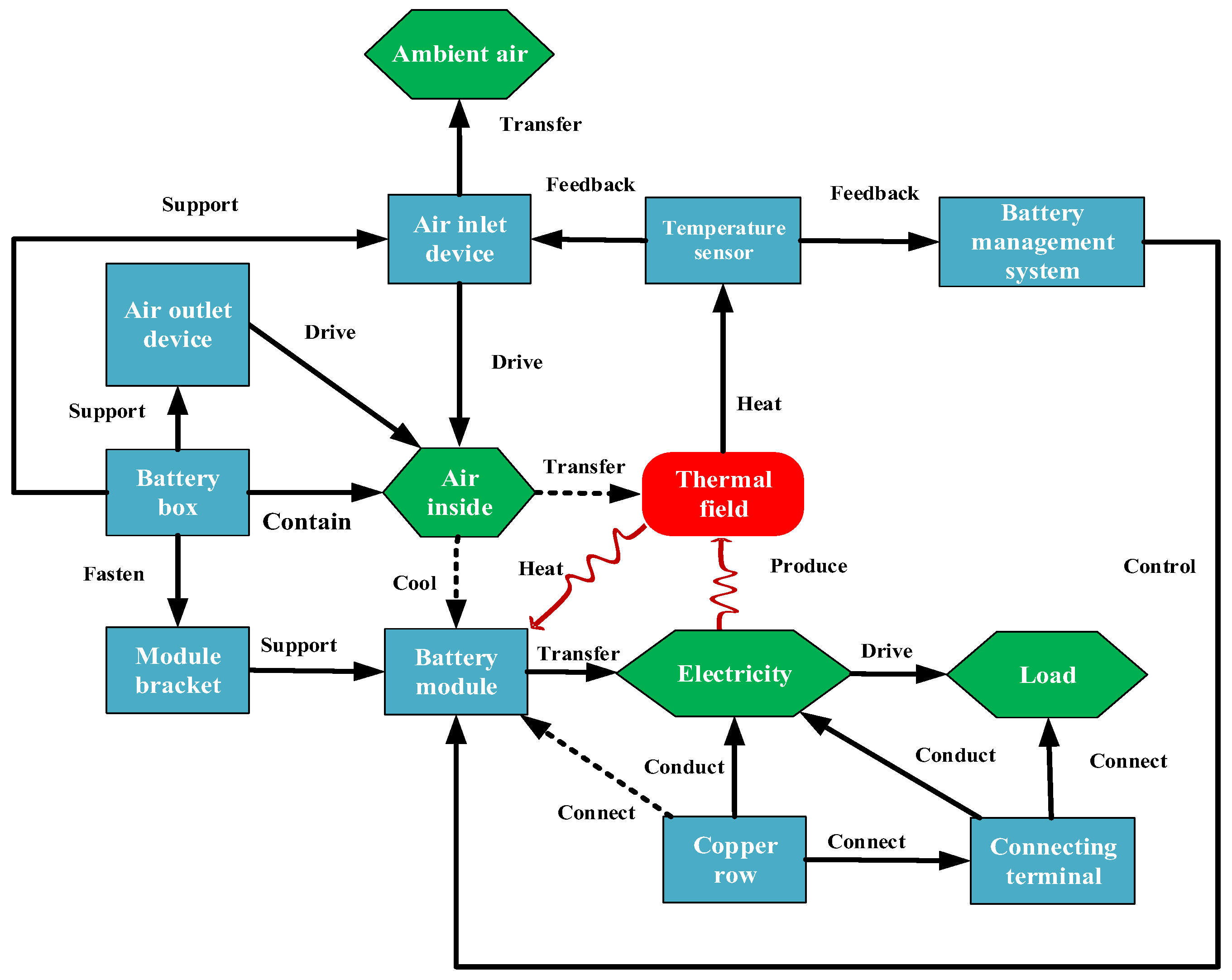
According to the process of function analysis in TRIZ theory, the engineering system should first be identified by components analysis. The system is formed of nine components, including the battery management system, the temperature sensor, the air inlet device, the air outlet device, the battery box, the module bracket, the battery module, the copper row, and the connecting terminal. Secondly, the interaction between each of the two components should be analyzed. Furthermore, the functional model is built, as shown in Figure 3.
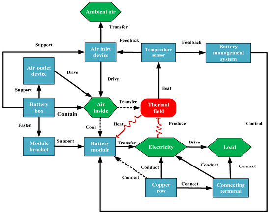
Figure 3.
The function model of a high-power locomotive battery module system.
It is clearly found in Figure 3 that the defects of the system for the high-power locomotive battery module system are all the defects generalized in Table 1.

Table 1.
The defect list of function model output.
Four defects were obtained by the function analysis, as shown in Table 1. Through analysis, the key problem was that the battery module could not effectively be cooled. Therefore, it means that if the cooling problem of the battery module has been solved, the goal of this system, that the working temperature and the temperature difference should be reduced, can be achieved. In this investigation, the ARIZ algorithm will be used to solve the problem.
3. Application Process of Ariz Algorithm
3.1. The Analysis of the System
3.1.1. Defining the Mini-Problem
The minimum problem is defined as a problem which requires finding a solution that minimizes changes to an existing engineering system. The current research technical system is the energy storage battery system, for which the main function is cooling the module. The technical contradiction has been used to help define the mini-problem, for which the description of technical contradiction is that in order to improve a parameter of the technical system, another parameter of the technical system deteriorates. Additionally, the contradiction composed of two parameters is called a technical contradiction. The technical contradictions in this engineering system problem are shown in Table 2. Therefore, the mini-problem defined is that it is necessary to improve the thermal conductivity of the energy storage battery module and ensure driving safety while keeping the engineering system unchanged, according to the two technical contradictions.

Table 2.
Positive and reverse technical contradiction for an engineering system.
3.1.2. Identifying Components in the Contradiction
In the engineering system, two functions will be implemented: (1) the energy storage rail vehicle is driven; (2) the battery module is heated. For these two functions, the objects of the function are the energy storage rail vehicle and the battery module, respectively.
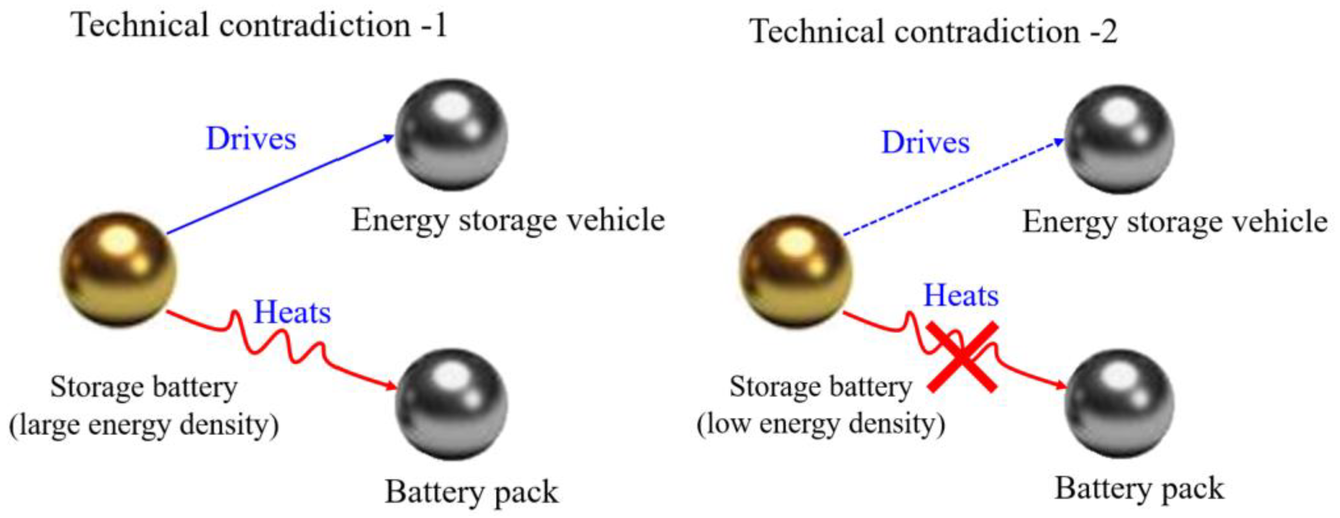
In the ARIZ algorithm, the contradiction pair is composed of a tool and product, which are used to identify the interaction between components. In the engineering system of this investigation, the tool is the energy storage battery (with high density and low density), and the product is the energy storage rail vehicle and battery module. The contradiction pairs are shown in Figure 4.
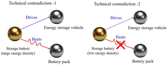
Figure 4.
The sketch of technical contradiction.
3.1.3. Intensifying Contradiction
In order to clarify the direction of problem-solving, one of the technical contradictions is selected to be solved, as illustrated in Figure 4. The evolution trend of the S-curve in TRIZ theory can be helpful in analyzing the evolution direction of products. Judging from the performance parameters, number of invention patents, the patent level, profit, and other indicators, the energy storage power supply products should be at the second stage of the S-curve. TRIZ theory has given the product development strategy of this stage, which is that optimization is the main method to develop a technical system. For the energy storage battery, the energy density still needs to be improved. Therefore, technical contradiction-1 is selected for a solution; that is, the energy density of the energy storage battery is improved, then the power of the energy storage rail vehicle is sufficient, but the heat generated by the battery module is large, and the safety performance is reduced.
The contradiction of the system must be intensified, which can effectively prevent the generation of a compromise scheme for project designers. The intensified technical contradiction-1 has been descripted as follows: the energy density of the energy storage battery has been infinitely improved, the power of the energy storage rail vehicle has been guaranteed, and the heat generated by the battery module is infinite.
In order to obtain more design schemes, the process of the ARIZ algorithm (ARIZ-85) in Figure 1 should be improved; the problem-solving process can start from the technical contradiction. Technical contradiction is a tool to solve problems in TRIZ theory, which can be solved by Altshuller’s contradiction matrix, and then the scheme can be obtained based on the tips for 40 invention principles [11,28,29]. The technical parameters were obtained in the technical contradiction-1, in which the improved parameter is “sufficient power” and the deteriorated parameter is “high thermal energy radiation”, respectively. The improved and deteriorated parameters were generalized the Altshuller’s technical parameters, in which “power” was selected as the improved parameter, and “harmful factors generated by objects” was selected as the deteriorated parameter, respectively, according to the definition of each of 39 Altshuller’s technical parameters. By consulting Altshuller’s contradiction matrix, three invention principles of invention were obtained, which were extraction (invention principle 02), the transformation of physical or chemical states of an object (invention principle 35), and mechanical vibration (invention principle 18), respectively.
According to the principle of invention (02), the principle of “extracting negative parts or attributes of objects” is extracted. Combined with professional knowledge, relevant technologies in which the heat in the charging and discharging process is reduced are adopted. The following two schemes have been obtained:
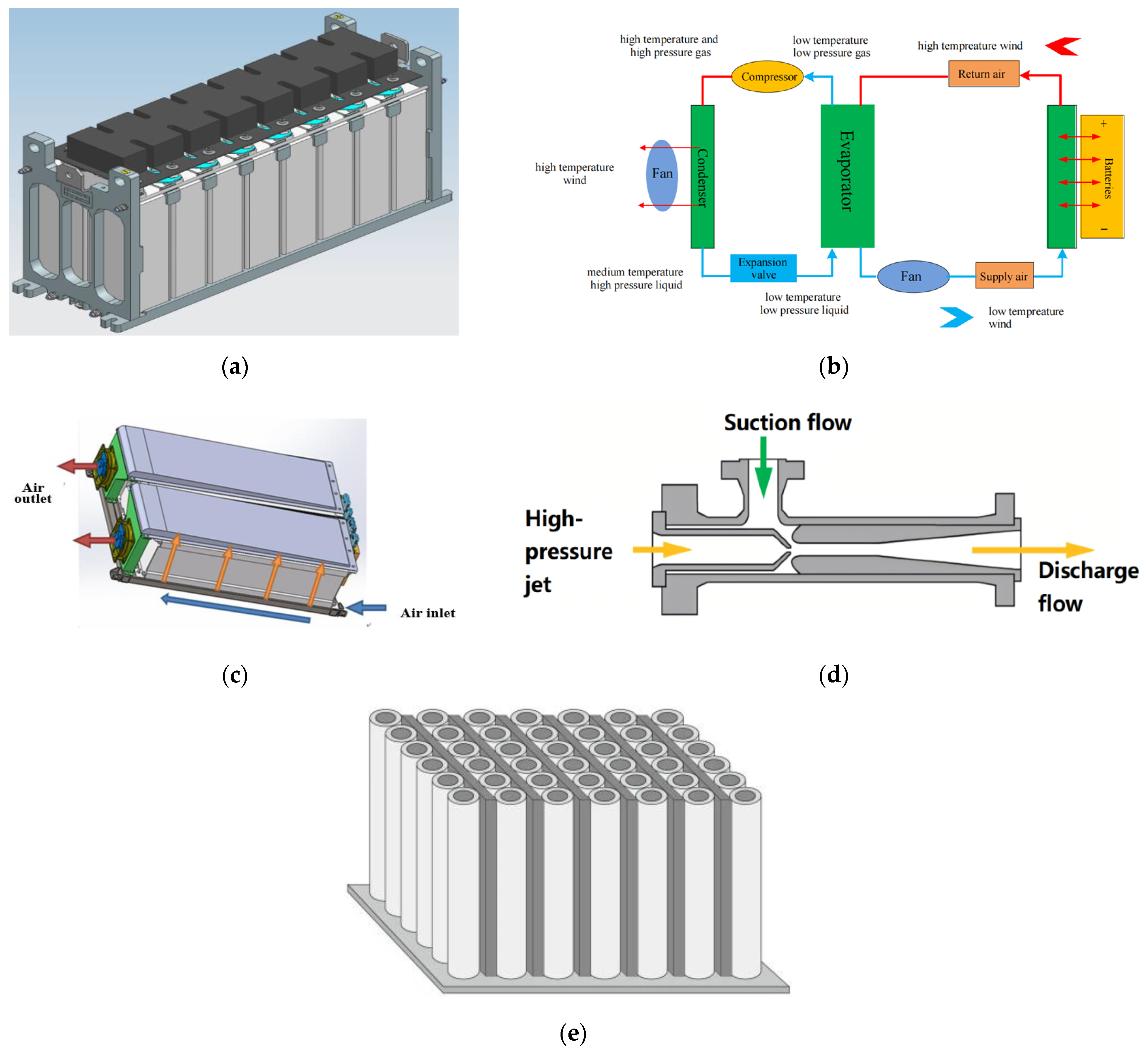
Scheme 1: The active DC/DC voltage-equalization method can be considered to be adopted for the battery module system, as shown in Figure 5a. The bi-directional voltage of the differential pressure cell can be considered to be controlled through the active DC/DC voltage-equalization mode. The specific design is that the high-voltage cell is discharged, and the low-voltage cell is recharged. The advantages of this design are that the energy of the cell can be effectively used, the energy loss of the energy storage system can be reduced, and the heat generation can be reduced.
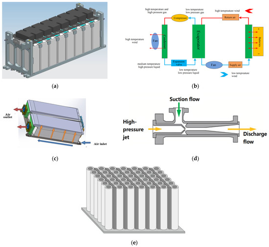
Figure 5.
The schematic diagrams of the schemes. (a) Active DC/DC voltage-equalization module of battery system; (b) Air conditioning temperature control system; (c) High-speed air suction device of battery module; (d) High-pressure jet device of battery module; (e) Air gel heat shield device for the battery module.
Scheme 2: Since the active graphene technology is still in the laboratory research stage, the material cannot be put into practical application. At present, the porous nano-activated carbon material should be preferentially considered for adoption for this reason at the present stage of battery material technology development. The porous nano-activated carbon composite energy storage battery should be considered to adopt in this scheme, in which the charge adsorption of the porous nano-activated carbon material is used for energy storage. The energy density of the battery is increased, the internal resistance of the battery is reduced, and the heat generation of the battery is reduced.
The description of the principle of invention (35) is the transformation of the physical or chemical states of an object. Combined with the tip of “changing the flexibility of objects” and professional knowledge, the deflector of the flexible shell is designed. According to the above ideas, the following schemes have been obtained:
Scheme 3: The semi-active flexible shell deflector based on flow induction can be considered to be used. The advantages of this design are that the area of the deflector can be increased, and the conductivity to the battery module can be increased due to the expansion of the flexible deflector with piezoelectric film on the surface under the action of fluid pressure.
The Su-field model is a very powerful tool of the well-known theory of inventive problem solving, which is solved by the 76 standard solutions. This TRIZ tool was created by G. Altshuller [30] between 1975 and 1985 as solutions for common inventive problems extracted from the studies of patents. The set of standards directly derives from the laws of technical system evolution, guiding the synthesis and transformation of these system by implicitly eliminating technical contradictions [31].
In practice, it is usually used in ARIZ [32] as part of the Substance-field analysis after the Su-field model has been built, and any constraints on the solution have been identified [33]. In the graph of technical contradiction-1, as shown in Figure 4, a harmful Su-field model is formed between battery modules of energy storage batteries. The solving tool of the Su-field model is 76 standard solutions in TRIZ theory, for which the standard solution in class 1.2 can be applied to solve the harmful Su-field model [34].
For this harmful Su-field model, the standard solution 1.2.4 is adopted, in which the field is used to offset the harmful effect. The description of this standard solution is that the harmful effect of field F1 is offset through the introduction of field F2. According to the suggestion of the standard solution 1.2.4, the temperature field or mechanical field should be considered to offset the harmful thermal field generated during the charging and discharging process. The following three solutions have been obtained.
Scheme 4: The air-cooled air conditioner for thermal management can be considered to be adopted for the battery system, as shown in Figure 5b. The mechanism of action is that the temperature radiated by the module can be sensed in real time by adding the air conditioning refrigeration device to the battery module. The temperature inside the control module can be controlled through the air conditioning frequency conversion unit, which the air conditioner may be automatically open and air-cooled for cooling of the battery when the maximum temperature of the battery reaches 38 °C.
Scheme 5: High-speed air suction device of the battery module can be considered to be adopted, as shown in Figure 5c. The working principle is that the density of air cooling flow inside the battery module can be increased through the negative generated by the pressure-designed high-speed fan inside the battery module.
Scheme 6: High-pressure jet device of the battery module can be used, as shown in Figure 5d. The core reason for heat dissipation in this scheme is the introduction of the high-pressure jet field inside the module. Specifically, the gas is compressed, and the negative pressure can be generated when the high-pressure gas passes through the variable cross-section nozzle of the jet ejector. It can lead to the increment of the cooling medium flow inside the battery module, the reason of which is that the airflow outside the module can be siphoned to the inside of the jet ejector.
The standard solution 1.2.1 can also be adopted to solve this harmful Su-field model. The description is that the harmful effect is eliminated when the external substance is introduced, which means that the substance S3 is introduced between substances S1 and S2, and then the harmful effect can be eliminated. According to the suggestion of the standard solution 1.2.1, it can be considered to add thermal insulation materials between the battery modules to block the harmful thermal field generated during the charging and discharging process. The following solution has been obtained.
Scheme 7: The porous aerogel thermal insulation material can be considered to be added to the battery surface, as shown in Figure 5e. The reason for the purpose of adding aerogel heat insulation material is that the material can be used to isolate the heat between the battery modules, for which the radiation of the thermal field among the modules can be reduced efficiently.
3.1.4. Determining the Mini-Problem
According to the above process of analysis, the mini-problem can be defined in the following form: An X factor is introduced, and then the harmful effects should be prevented by factor X, and useful effects should be maintained. The X factor may be a kind of material and may be a parameter, which the introduction of the X factor will not complicate with the analyzed engineering system, nor will additional harmful effects be introduced.
The mini-problem in this investigation is defined as: it is necessary to introduce the X factor, which can not only meet the requirement for increasing the energy density of energy storage batteries but also achieve the effect of effective heat dissipation.
3.2. The Analysis of Resources
3.2.1. Opening Zone Analysis
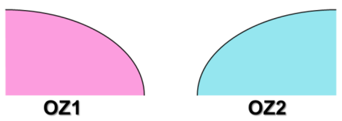
The specific spatial area executed by the system function is analyzed to determine whether two functions have been executed in the same area or different areas. As shown in Figure 6, OZ1 is the area where the energy storage rail vehicle is driven, while OZ2 is the area where the battery module is heated, respectively. In this system, the driven area of the energy storage rail vehicle is outside the energy storage battery, while the heated area of the battery module is inside the energy storage battery, respectively. It can simply be inferred that OZ1 and OZ2 are different executed areas, and the schematic diagram of the operation space for function execution has been shown in Figure 6. Therefore, the conflicting of the parameter can be separated in space, according to the solving tool of physical contradiction [11], for which this parameter can be solved by the space separation principle.
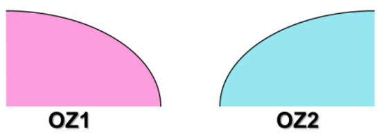
Figure 6.
Operating space for function execution.
The space separation principle recommended six invention principles, including segmentation (invention principle 01), taking out (invention principle 02), local quality (invention principle 03), nested doll (invention principle 07), asymmetry (invention principle 04), and another dimension (invention principle 17). In this investigation, the invention principle (17) of space separation is adopted. The description, another dimension, is that moving or stationary objects in one-dimensional space are changed into those in two-dimensional space, and objects in two-dimensional space are changed into those in three-dimensional space. According to the tip of this inventive principle, the thought that the heat dissipation area of the battery surface is increased through dimensional change should be considered. The following scheme has been obtained.
Scheme 8: Fin surface structure can be considered to adopt, as shown in Figure 7a. Using this design scheme, the heat dissipation area of the battery module can be increased efficiently due to the increased fin structure on the battery surface.

Figure 7.
The schematic diagrams of the schemes. (a) The fin heat dissipation device of the battery module; (b) The structure of the radial flow deflector; (c) The orthogonal nested deflector of the battery module.
According to the recommended inventive principle (1) of space separation, and segmentation, it can be described that an object is divided into mutually independent parts. It is considered that multiple independent structures are used to transfer heat, and the following solution has been obtained.
Scheme 9: A radial flow deflector structure can be considered to be designed, as shown in Figure 7b. The guide area can be increased efficiently by conducting the flow through the amplitude flow blade.
The invention principle (7) by the space separation, nested doll, is described as “one object passes through the cavity of another object”. The thought that added multiple guided structures should be considered. The following scheme has been obtained.
Scheme 10: A kind of orthogonal nested deflector can be considered to be designed, as shown in Figure 7c. The diversion area can be increased efficiently by orthogonally embedding diversion structures of different sizes on the diversion plate.
3.2.2. Operating Time Analysis
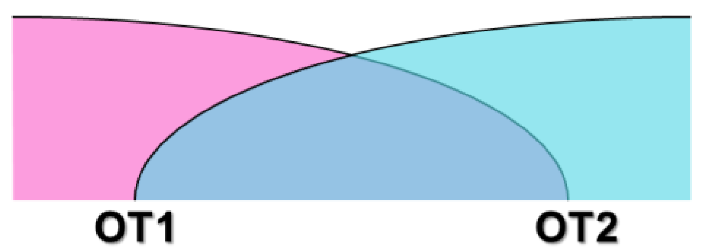
The specific execution time of the system function has also been analyzed to determine whether two functions are executed in the same time period or different time periods. As shown in Figure 8, OT1 is the time when the energy storage rail vehicle is driven, while OT2 is the time when the battery module is heated, respectively. The time for the energy storage rail vehicle to be driven and the time for the battery module to be heated are both the time periods for train operation. Therefore, OT1 and OT2 are the same, which means that the contradictory parameter cannot be separated in time.
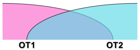
Figure 8.
Operating time of function execution.
3.2.3. The Analysis of Substance and Field Resources (SFR)
Resources refer to the objective existence that can be used. In TRIZ theory, resource analysis focuses on selecting the operation space where conflicts occur, the operation time when conflicts occur, and the materials and fields of the engineering system and their super-system. Substance and field resources may be materials, fields, and parameters, and also may be time and space. Substance and field resources can be divided into two types, including system resources and super-system resources. The system resources can be divided into tool resources and product resources. According to the technical problems solved in this investigation, the field resources that may be used are shown in Table 3.

Table 3.
The substance and field resources of system.
3.3. Definition of the Ideal Final Result and Formulation of the Physical Contradiction
3.3.1. The Formulation and Description of the Ideal Final Result (IFR)
In TRIZ theory, the ideal final result (IFR) of the problem through idealization has usually been defined without various objective constraints to try to obtain the solution. The purpose is to clarify the direction and location of the ideal solution, which ensures that the process of problem-solving can develop along its goal and that the final ideal solution can be successfully obtained. It can effectively avoid the drawbacks of the lack of goals in traditional innovation methods, and it also can improve the efficiency of innovative design.
IFR-1 can be described by the introduction of the X factor. During the operation space and time, harmful effects are eliminated, and the working performance is maintained. Then, the result of the introduced X factor is that harmful system can be eliminated (insufficient heat dissipation), while the main function can be executed (the energy storage rail vehicle is driven) during the operating time (during the operation period of the energy storage rail vehicle) and in the operation space (outside the energy storage battery) without making the system more complex, and without any harmful consequences being generated. Finally, IFR1 should be strengthened. The existing resources (resources in Table 2) in the current system were used to replace X elements one by one. The replacement results have been as follows:
- (1)
- Based on the analysis of the substance and field resources of system, the number of fans can be an X factor introduced above and solved by IFR. The IFR-1 describes that the number of fans can eliminate the harm (insufficient heat dissipation) and perform the main functions (the energy storage rail vehicle is driven) in the operating time (the time-operating period of the energy storage rail vehicle) and in the operating space (except for the energy storage battery) without making the system more complex, without any harmful consequences being generated. The following solution can be obtained:
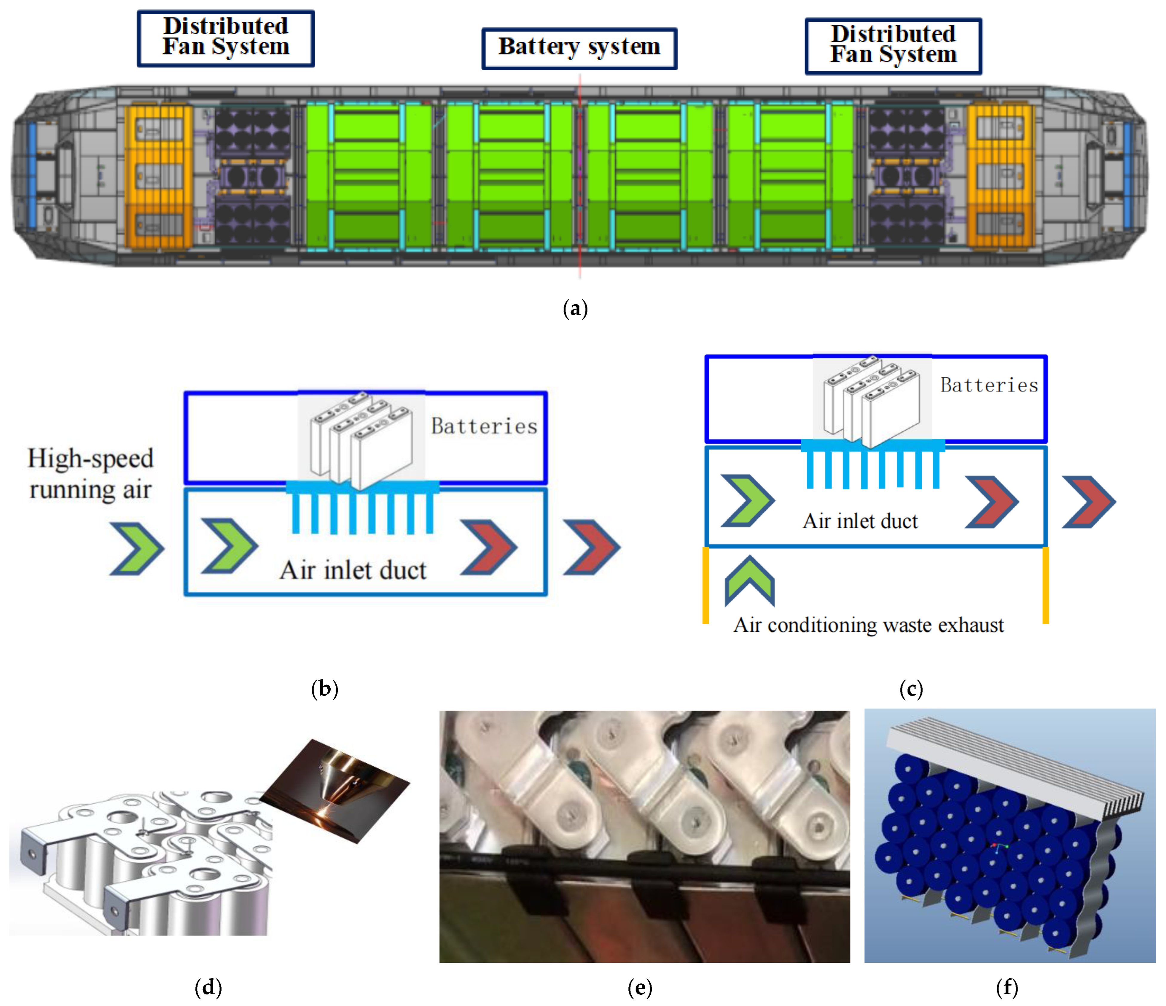
Scheme 11: A distributed fan cooling system can be considered for an energy storage power system, as illustrated in Figure 9a. The working principle is that a single high-power fan should be divided into multiple low-power fans, the purpose of which is that the heat dissipation performance of the energy storage system can be further increased while the space volume of the energy storage system should not be increased.
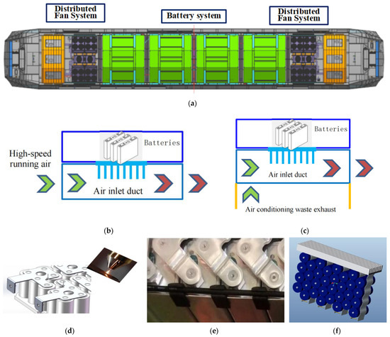
Figure 9.
The schematic diagrams of the schemes. (a) Distributed fan cooling system of energy storage power system; (b) High-speed running air supply system; (c) Air supply system for waste air exhaust of passenger compartment; (d) The copper bar and the single pole are welded; (e) Filling of conductive paste in the space between the copper bar and monomer; (f) Plate type super-conducting heat pipe cooling system.
- (2)
- The air supply system can be another X factor introduced above and solved by IFR. The IFR-1 can be described as the air supply system that can eliminate the harmful effects (insufficient heat dissipation) and perform the main functions (the energy storage rail vehicle is driven) during the operating time (during the operation period of the energy storage rail vehicle) and in the operation space (except for the energy storage battery) without making the system more complex, and without any harmful consequences being generated. The following solutions can be obtained:
Scheme 12: The high-speed running air supply system of the train is considered to adopt, as shown in Figure 9b. The working principle is that the compressed air at the head of the train causes negative pressure in front of the cab when the train is moving at high speed, and then the high-speed shaped air can be used as the air supply system for the heat dissipation of the train.
Scheme 13: The waste air exhaust and cooling air supply system of the passenger compartment air conditioner can be adopted, as shown in Figure 9c. The working principle is that the waste exhaust cold air of the air conditioner in the passenger compartment is used as the air supply system of the battery system in order to achieve the goal of heat dissipation.
- (3)
- The contact mode between the copper bar and the battery can be seen as the third X factor introduced above and solved by IFR. The IFR-1 can be described as the contact mode between the copper bar and the battery that can eliminate the harmful (insufficient heat dissipation) and perform the main functions (the energy storage rail vehicle is driven) in the operating time (the time-operating period of the energy storage rail vehicle) and the operating space (except for the energy storage battery) without making the system more complex, and without any harmful consequences being generated. The following solutions can be obtained:
Scheme 14: The copper bar and single pole can be considered to be welded, as shown in Figure 9d. The purpose of the welding copper bar and unipolar is that the contact area between the copper bar and the single pole can be increased; meanwhile, the contact resistance between them is reduced. It can efficiently reduce heat.
Scheme 15: The method of adding conductive paste between a copper bar and monomer can be adopted. The filling of conductive adhesive in the space between the copper bar and the monomer can conclude that the conductivity of the copper bar can be further increased, and the heating of the copper bar can be reduced. The scheme is shown in Figure 9e.
- (4)
- The heat dissipation device can be the fourth X factor introduced above that can be solved by IFR. The IFR-1 can be described as the heat dissipation device that can eliminate the harmful (insufficient heat dissipation) and perform the main functions (the energy storage rail vehicle is driven) in the operating time (during the operation period of the energy storage rail vehicle) and the operating space (except for the energy storage battery) without making the system more complex, and without any harmful consequences being generated. The following solutions can be obtained:
Scheme 16: The plate-type super-conducting heat pipe can be considered to be placed among the batteries, as shown in Figure 9f. The purpose of this approach is that the battery heat is quickly exported through the phase change material in the super-conducting heat pipe.
3.3.2. The Formulation of the Physical Contradiction
- (1)
- Macro-Physical Contradiction
Physical contradiction can be divided into macro and micro aspects. On the macro level, the introduction of the X factor will not only meet the demand of the energy storage rail vehicle to be driven but also meet the good heat dissipation performance of the energy storage battery. Based on the analysis of the substance and field resources of this system, the number of condenser fans may be selected as the fifth X factor. Then, the model of physical contradiction can be described as follows: the number of condenser fans should be large, for which the reason is that the heat dissipation demand of the condenser must be met, but the number should be small. The reason is that the installation space of the vehicle is limited. The physical contradiction can be separated by relation separation. According to the suggestions of the invention principle 03 (local quality) and the invention principle 17 (another dimension), the following two schemes can be obtained, respectively.
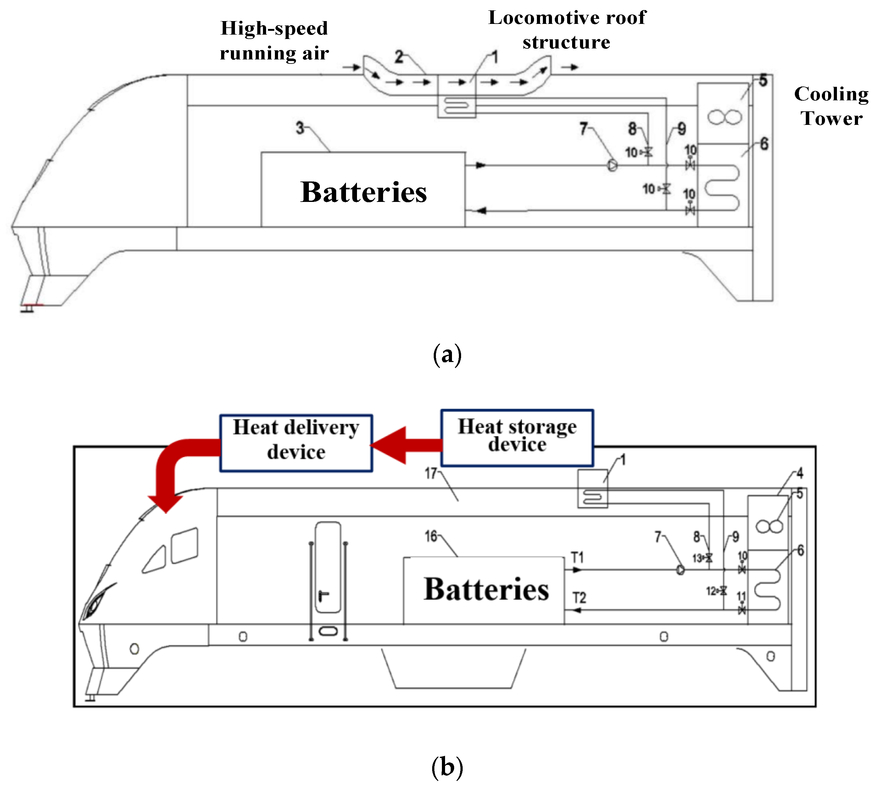
Scheme 17: The combined heat dissipation device of the locomotive roof structure, high-speed running wind, and cooling tower can be considered to be designed. The working principle is that the heat generated by the energy storage power supply can be distributed to the locomotive roof and the cooling tower; meanwhile, the car body metal top cover, high-speed running air, and cooling-tower fan are used for heat dissipation, as shown in Figure 10a.
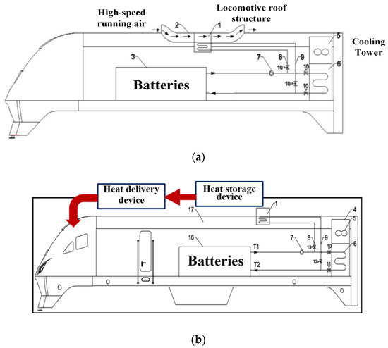
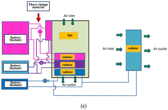
Figure 10.
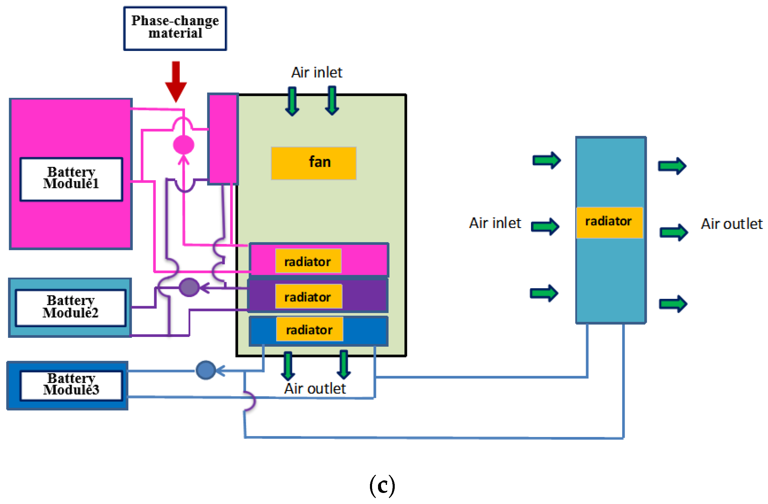
Schematic diagrams of the schemes. (a) The combined heat dissipation device of the locomotive roof structure, high-speed running wind, and cooling tower [35]; (b) Heat storage and delivery device; (c) Phase heat exchanger for battery system.
Scheme 18: The heat absorption and transmission device of the energy storage power supply is considered to be designed. The purpose of this design is that the heat generated by the energy storage power supply is quickly absorbed and transmitted to the cab for supply heating, as shown in Figure 10b.
- (2)
- Micro-Physical Contradiction
Based on the analysis of the substance and field resources of this system, the air molecules are selected as the sixth X factor. The heat generated needs to be absorbed and released during the charging and discharging process. From a microscopic perspective, it is the contradiction between the limited absorption and release capacity of air molecules for heat and the heat generated during charging and discharging. The satisfaction principle is adopted to solve the physical contradiction. According to the tip of the invention principle 36 (phase transition), the following scheme can be obtained:
Scheme 19: In Figure 10c, the phase heat exchanger can be considered to be adopted for the battery system, the working principle of which is that the latent heat of phase change can be used to absorb and release heat.
3.4. Application of Substance and Field Resources (SFR)
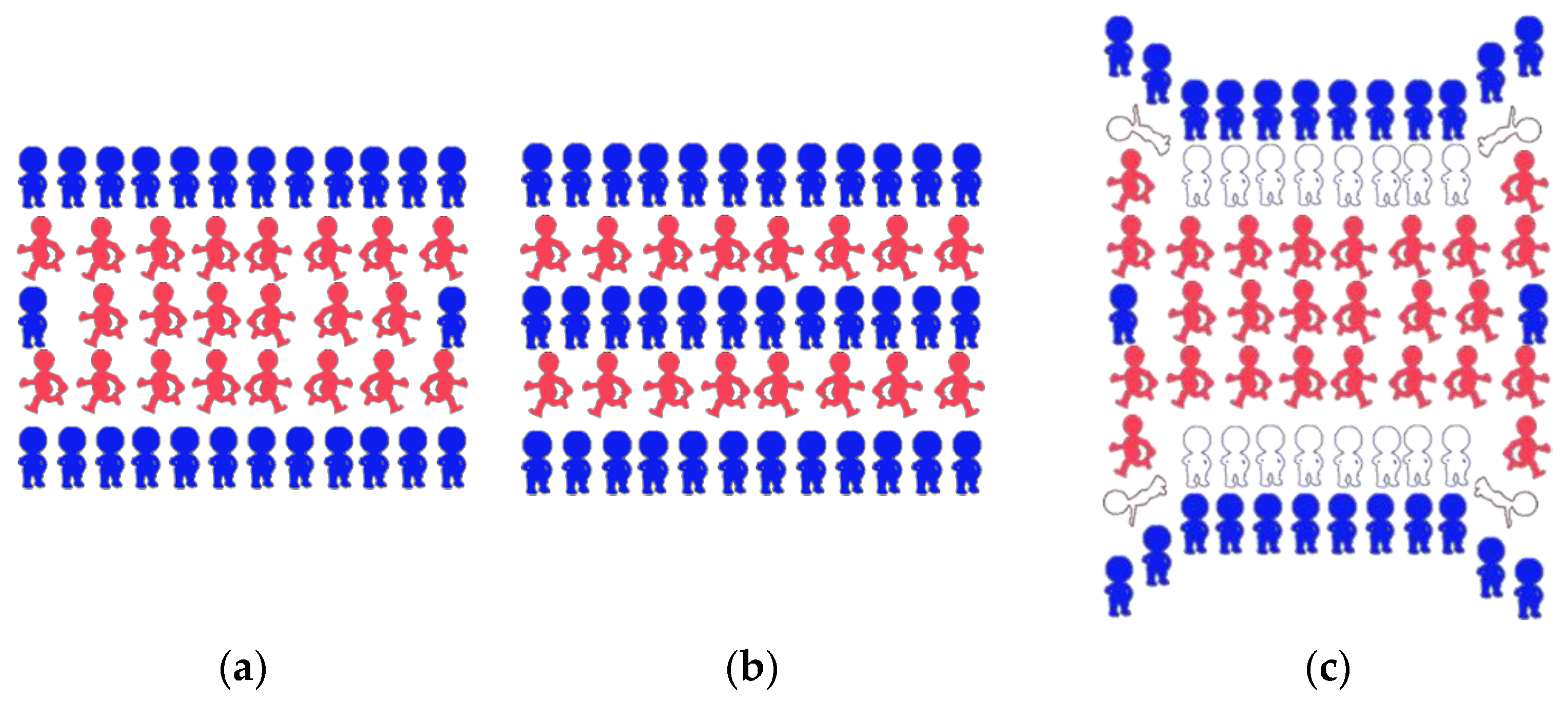
In order to obtain more conceptual solutions for screening, ARIZ should be used to continue the analysis. The problem could be solved by the method of small smart people, which is an important thought tool of TRIZ theory that can effectively break the inertia of thinking. As shown in Figure 11, the battery module is represented by the blue small smart people, and the heat is represented by the red small smart people. The establishment of the problem model is shown in Figure 11a. After personification, the scenario can be described as the red people needing to escape from the surrounding of the blue villain, and the space surrounded by the blue people is too small, which directly leads to the red people being more crowded when escaping.
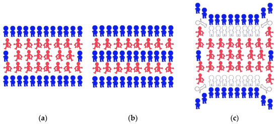
Figure 11.
Schematic diagram for a method of small smart people for problem model (a); solution model 1 (b); solution model 2 (c).
The small people of different colors in the problem model need to be reorganized. The first reorganization pattern is that the blue people need to be reorganized, which can form multiple channels to make it easy for the red people to escape. The problem-solving model is shown in Figure 11b. According to the hints of the reorganization pattern, the following scheme can be obtained.
Scheme 20: A multi-layer air diversion device can be considered for battery modules, as shown in Figure 12a. The working principle is that the flow deflector should be increased in the layer of space of the battery module monomer in order to increase the battery monomer of the flow diversion.

Figure 12.
Schematic diagrams of the schemes. (a) Multi-layer air diversion device; (b) Battery module diversion structure.
Scheme 21: As shown in Figure 12b, the space of the battery module can be considered to be divided to form multiple airflow channels, the purpose of which is that the module monomer conducts multi-layer diversion and heat dissipation in order to increase the cooling airflow of the module.
Another reorganization pattern is that the white people are introduced to help the red people escape from the encirclement of the blue people. The problem-solving model is shown in Figure 11c. According to the tip of the reorganization pattern, the following scheme can be obtained.
Scheme 22: The thermal expansion metal material can be considered to be adopted and designed as the surface of the bimetallic battery. The purpose of this approach is that the bimetallic sheet can be used to deform when heated in order to improve the heat dissipation effect.
4. Determination of the Final Design Scheme
4.1. The Evaluation of Schemes
Summarizing all schemes obtained by the ARIZ algorithm, the schemes can be divided into eight types based on the thermal control mechanism, as listed in Table 4. Type 1 is mainly to improve the thermal control of the battery and its connected copper bars, including schemes 1, 2, 14, and 15, respectively.

Table 4.
The classification of all schemes.
The thermal control mechanism for type 2 is that the property of heat dissipation for the vehicle energy storage power supply has been improved by the improvement of the air supply apparatus. In this investigation, the variable frequency air conditioning, high-speed running air, air conditioning waste exhaust, and other air supply resources as the air supply apparatus can be improved. The schemes of this type include schemes 4, 12, and 13, respectively.
The thermal control mechanism for type 3 is that the negative pressure of high-speed air absorption and high-pressure gas compression have been used to increase the cooling, including schemes 5 and 6.
The adopted technology for type 4 is mainly that of using the different diversion structures to guide the energy storage batteries, which includes schemes 3, 9, 10, 20, and 21, respectively. In this type, the property of deformation produced by the piezoelectric conductive plate scheme introduced by scheme 3 is an important direction of semi-active and active diversion structure technology.
The schemes of type 5 are based on the phase change heat dissipation technology, including schemes 16, 17, 18, and 19, respectively. The thermal control mechanism is that the heat of the energy storage battery can be quickly exported through the super-conducting phase change material by the condenser or the heat dissipation resources of the super-system.
Type 6 includes schemes 8 and 22, in which the main mechanism is that the property of the heat dissipation for the battery can be improved by increasing the heat dissipation surface area of the battery.
The action mechanism of type 7 is the use of thermal insulation material, for which the concrete scheme is that using the aerogel heat insulation plate introduced by scheme 7 as the thermal insulation material to isolate the heat between the battery modules can effectively reduce the radiation of the thermal field.
The principle of scheme 11 as type 8 is that the distributed fan system has been used in the heat transfer of the battery system, which can greatly improve the heat dissipation performance, meanwhile, decrease the volume of setting space.
It can be clearly concluded in Table 4 that the problem of heat dissipation of an energy storage supply system for high-power locomotives can be solved along eight design concepts. Considering the actual requirement of the engineering project, the final design scheme can be considered obtained through three design concepts, which are the improvement of the thermal control of the battery and its connected copper bars (type 1), improvement of the air supply apparatus (type 2), and the use of the different diversion structures that guide the energy storage batteries (type 4), respectively.
In order to obtain the final design scheme, the above 22 schemes would be further analyzed by the ideality, which can be described by the five parameters of heat compensator dispersion, reliability and safety, system complexity, maintenance convenience, and cost of each solved scheme in this investigation.
The ideality [36] in the TRIZ theory reflects the adaptability of the technical system to social needs in the process of evolution, which can be used to evaluate each solved scheme. The calculation formula of ideality can be given as:
where FU is the score of useful function, FH is the score of harmful function, and C is the score of cost, respectively. In this investigation, the useful function includes the functions of heat compensator dispersion, reliability and safety, and maintenance convenience. Additionally, the harmful function includes the function of system complexity. The scores of each function for all schemes had been given by some technical experts, and the average score of each function is also listed in Table 5, where the parameter FA is the function score of heat compensator dispersion, FB is the function score of reliability and safety, FC is the function score of system complexity, and FD is the function score of maintenance convenience, respectively. The total score of each function has also been given in Table 4, in which the distribution of scores is 30, 30, 20, 10, and 10, respectively.

Table 5.
The evaluation of all schemes.
It should be noted that the higher FC score and C score mean that the system is less complex and the system cost is lower, respectively. The Formula (1) for the calculation formula of ideality in this investigation can be modified as:
where TotalFC is the total function score of system complexity and TotalC is the total score of cost, respectively. The ideality of each scheme can be calculated by Formula (2) and then sorted by the score values for all schemes, which are also listed in Table 4.
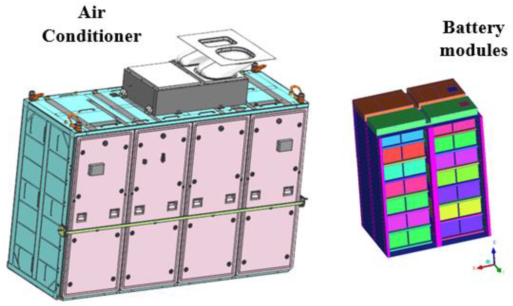
Finally, the final design scheme can be obtained by the overall consideration of the four analyzed design directions and the ranking of the ideality. The schemes with the higher ranking of the ideality in the determined types 1, 2, 3, and 4 are selected for combination to obtain the final scheme. The final design scheme is that the temperature of the battery system can be controlled by the combination design of schemes 1, 4, 5, 14, 15, 20, and 21. It means that the final scheme has included the mode of the multi-layer current diversion both in the module’s inner and outer space (schemes 20 and 21), the active voltage balancing method of the battery module (schemes 1), the use of intelligent variable frequency control cooling system (schemes 4), the use of a high-speed air suction device (schemes 5), the design of welding of copper bar and single pole (schemes 14), and the design of increasing conductive paste between a copper bar and monomer (schemes 15). The 3D model of the air conditioning cooling system for battery modules is shown in Figure 13.
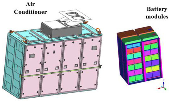
Figure 13.
3D model of air conditioning cooling system for battery modules.
It should be noted that other schemes of the higher ranking of the ideality can also be considered to adopt the corresponding engineering requirements.
4.2. The Verification by Numerical Simulation
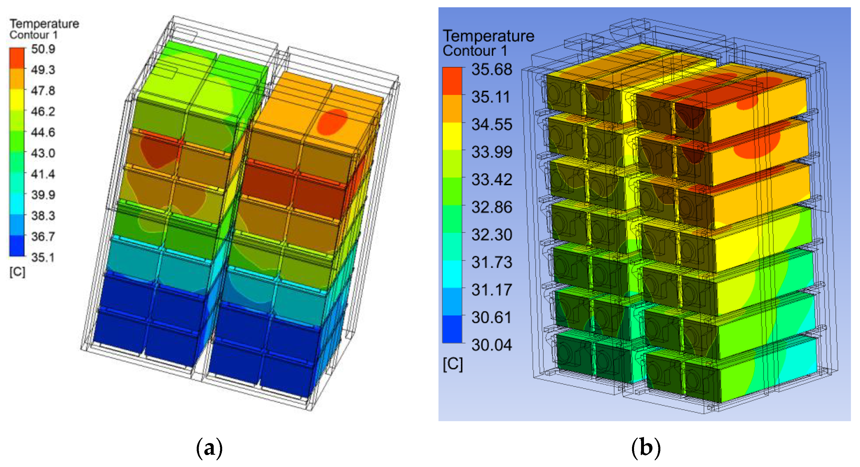
The optimized scheme of the heat dissipation for the energy storage power system, combined with schemes 4, 5, 20, and 21, had been simulated and analyzed by computational fluid dynamics software (ANSYS fluent). According to the air volume and temperature conditions of the heat dissipation scheme of the energy storage power box, the battery box module is cooled by using the inlet cold air temperature of 28 °C and the cold air volume of 800 m3/h. The inlet adopts the speed inlet boundary condition; the equivalent speed is 5.31 m/s, the outlet is the pressure outlet boundary condition, and the reference pressure value is set to 0 Pa. The internal wall of the energy storage power box is the non-slip coupling boundary condition, the external wall is the heat exchange boundary condition of natural convection with the external environment, the ambient temperature is set to 40 °C, and the heat transfer coefficient is set to 8 W/m2K. The fan inside the module is set to the pressure curve of the fan. The temperature distributions of the battery module for the optimized scheme and original scheme have been shown in Figure 14, respectively.
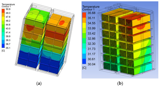
Figure 14.
The temperature distributions of the battery module for the original scheme (a) and optimized scheme (b).
It is clearly found in Figure 14a that the maximum temperature of the module surface is 50.9 °C for the original scheme, and the minimum temperature is 35.1 °C in the temperature distribution of the module. The maximum temperature difference of the module is 15.8 °C. The optimized scheme has also been given in Figure 14b, in which the result is that the maximum temperature of the module surface is 35.68 °C, the minimum temperature is 30.04 °C, and the maximum temperature difference of the module is 5.6 °C. The internal temperature difference of the battery cooling system has been decreased from 15.8 °C to 5.6 °C after optimization, according to the calculation. It can be concluded that the non-uniformity of the temperature distribution for the battery module can be effectively reduced by this optimization. The result shows that the maximum temperature of the module surface is 35.68 °C, and the maximum temperature difference of the module is 5.6 °C, which means that the optimization goal (the working temperature must be reduced to below 38 °C, and the temperature difference must be reduced to below 6 °C) has been achieved in this investigation.
It should be noted that if the heat dissipation effect produced by schemes 1 and 14 have been considered, the maximum temperature of the module surface should reduce to below 35.68 °C, and the maximum temperature difference of the module should reduce to below 5.6 °C.
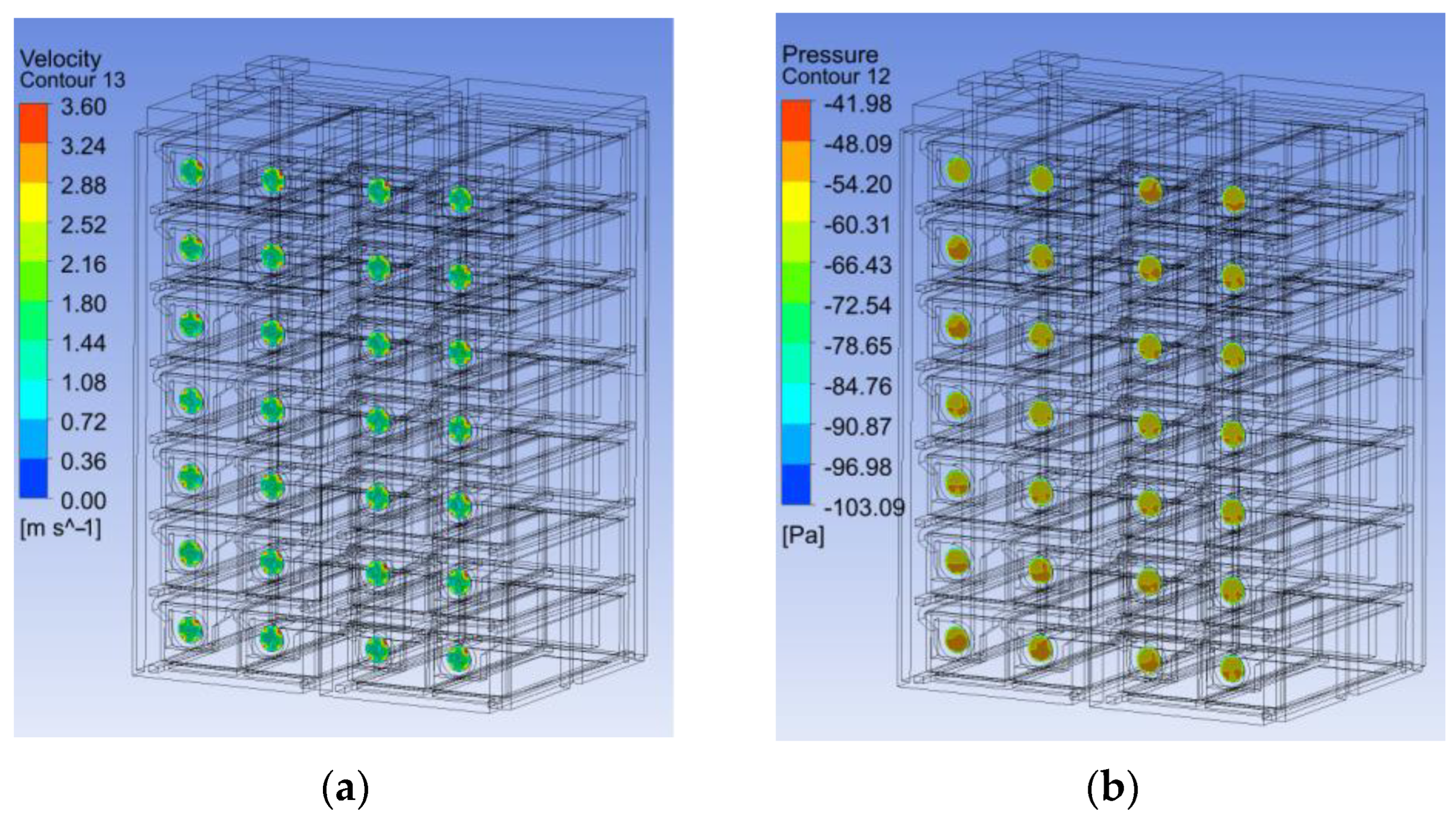
The velocity and pressure distributions for the independent fan surface (Scheme 5) of the battery module in the optimized scheme have also been simulated, and the results are shown in Figure 15a,b, respectively. The simulation results show that the velocity and pressure distributions of the exhaust fan for the 28 battery modules are uniform. The conclusion is that the ventilation air volume of each battery module is uniform for the optimized design scheme.
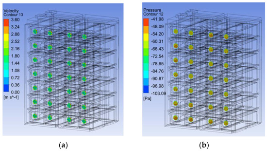
Figure 15.
The velocity (a) and pressure (b) distributions for the independent fan surface of the battery module in the optimized scheme.
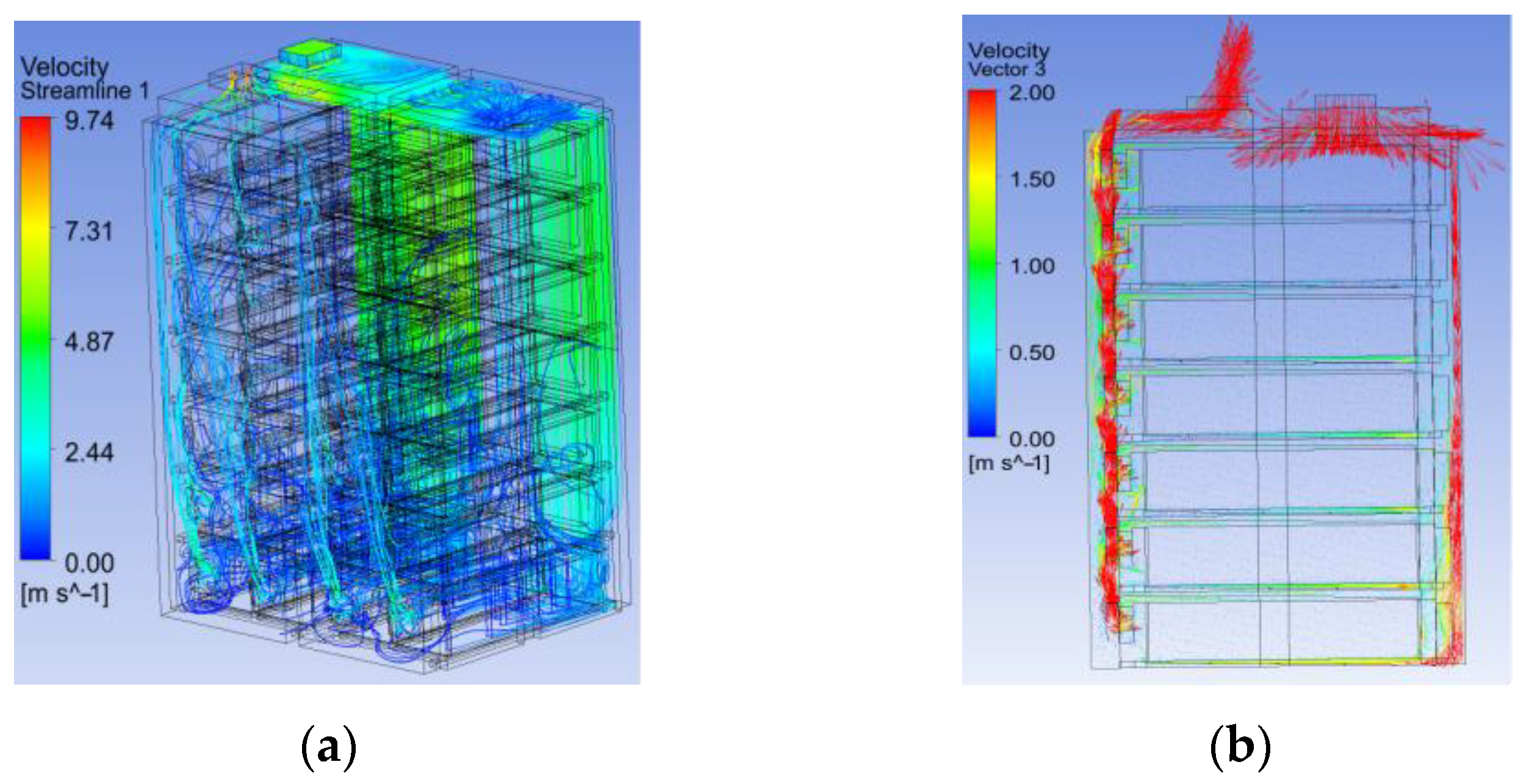
The airflow streamlines and velocity vector distributions inside the battery box of the optimized scheme have been simulated, and the results are shown in Figure 16a,b, respectively. The calculation results show that the airflow field uniformity of the module has been greatly improved by optimizing the structure of the power supply box.
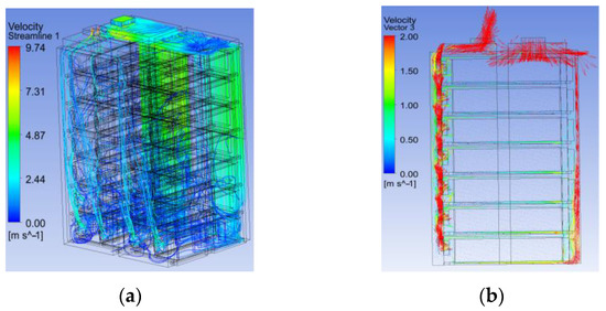
Figure 16.
The airflow streamlines (a) and velocity vector (b) distributions inside the battery box of the optimized scheme.
5. Conclusions
This paper used the ARIZ algorithm to deal with the problem of heat dissipation in the energy storage battery of a high-power locomotive. A total of 22 innovation schemes have been obtained by the improved algorithm. The ideality in TRIZ theory has been used to evaluate all the schemes after classification based on the thermal control mechanism, and then the final design scheme has been combined with the seven schemes (Schemes 20, 21, 1, 4, 5, 14, and 15). Based on the simulation results of the partially improved system in the optimized scheme, the heat compensator dispersion of the air conditioning cooling system for battery modules has reached design goals in this investigation, which the maximum temperature of the module surface has reduced to below 35.68 °C, and the maximum temperature difference of the module has reduced to below 5.6 °C.
The innovative schemes by the ARIZ algorithm provide flexibility in the process of solving engineering problems, and the full deployment (Part 3) of the improved ARIZ algorithm is applied to get suitable solutions for solving heat dissipation of energy storage supply system. Even though the research is dedicated to the improvement of the heat dissipation system, the pattern of the TRIZ approach in the paper could be applied to other product designs, and the paper is the perfect case study for the full procedure of the ARIZ algorithm for the product design and improvement of the high-power locomotive.
Author Contributions
Conceptualization, X.L.; data curation, S.C. and G.J.; formal analysis, D.L. and S.C.; funding acquisition, D.L.; investigation, D.L., S.C. and Y.Z.; methodology, D.L.; project administration, L.S.; resources, Z.L. and A.Q.; supervision, X.L. and L.S.; validation and software, G.J., Z.L. and Y.Z.; writing—original draft, D.L.; writing—review and editing, L.S. and X.L. All authors have read and agreed to the published version of the manuscript.
Funding
This research was partially supported by the Ministry of Innovation Special Projects Funding of the Ministry of Science and Technology, China, under Grant No. 2019IM05010. The first author would like to acknowledge the support from the project of the China Postdoctoral Science Foundation (Grant No. 256069).
Institutional Review Board Statement
Not applicable.
Informed Consent Statement
Not applicable.
Data Availability Statement
The data used to support the findings of this study are included in the article.
Conflicts of Interest
The authors declare no conflict of interest.
References
- Mao, Y.; Long, Y.; Chen, S.; Xiao, X. New E-E Hybrid Power Drive Energy Package for Rail Transit. Electr. Loco-Motiv. Mass Transit Veh. 2020, 41, 7–11. [Google Scholar]
- Qiao, Z.; Ruan, D. Application of Supercapacitors in Urban Rail Transit Vehicles. Railw. Loco-Motiv. Car. 2019, 39, 83–90. [Google Scholar]
- Luo, L.; Song, W.; Lin, S.; Lv, J.; Chen, Y.; Feng, Z. Research Progress on Effects of Temperature on SOC and Its Estimation for LFP Battery. Adv. New Renew. Energy 2015, 3, 59–69. [Google Scholar] [CrossRef]
- EN 45545-2; Railway Applications-Fire Protection of Railway Vehicles-Part 2: Requirement for The Fire Behaviour of Materials and Components. EN (European Committee for Standardization): Brussels, Belgium, 2013.
- Li, X.; Fu, G.; Zhao, R.; Deng, Y. Heat Dissipation Simulation and Design Optimization of Modern Tram Super Capacitor Energy Storage Cabinet. Mod. Urban Transit 2019, 1, 11–15. [Google Scholar]
- Fu, Y.; Wen, W.; Li, Y. Heat Dissipation Design of Energy Storage Power Supply for a Strong Hybrid EMU. Electr. Loco-Motiv. Mass Transit Veh. 2021, 44, 30–34. [Google Scholar]
- Yang, Y.; Zhou, P. Simulation and Optimization of Heat Dissipation of Energy Storage Power Supply for a Hybrid EMU. Electr. Locomot. Mass Transit Veh. 2020, 43, 6–9. [Google Scholar]
- Xueting, F.; Boxuan, Y.; Huabo, C.; Chaohua, D. Survey on Super-Capacitor Thermal Management System for Rail Transit. Chin. J. Power Sources 2019, 43, 1403–1406. [Google Scholar]
- De Rosa, R.; Romagnuolo, L.; Frosina, E.; Belli, L.; Senatore, A. Validation of a Lumped Parameter Model of the Battery Thermal Management System of a Hybrid Train by Means of Ultrasonic Clamp-On Flow Sensor Measurements and Hydronic Optimization. Sensors 2023, 23, 390. [Google Scholar] [CrossRef]
- Zhang, L.; Tan, R.; Peng, Q.; Dong, Y.; Sun, J. Function Integrated Product Innovation Base-d on Laws of Need Evolution. Comput.-Aided Des. Appl. 2023, 20, 133–146. [Google Scholar] [CrossRef]
- Peng, S.; Runhua, T.; Qingjin, P.; Chuan, H.; Fang, L.; Yafan, D. A Hybrid Model for Acquisition an Devaluation of Product Innovation Solutions. Comput.-Aided Des. Appl. 2023, 20, 119–132. [Google Scholar] [CrossRef]
- Peng, S.; Runhua, T.; Qingjin, P.; Lulu, Z.; Kang, W.; Yafan, D. Problem-Solving in Product Innovation Based on the Cynefin Framework-Aided TRIZ. Appl. Sci. 2022, 12, 4157. [Google Scholar] [CrossRef]
- Nie, Z.; Cao, G.; Zhang, P.; Peng, Q.; Zhang, Z. Multi-Analogy Innovation Design Based o-n Digital Twin. Machines 2022, 10, 652. [Google Scholar] [CrossRef]
- Shao, P.; Tan, R.; Peng, Q.; Yang, W.; Liu, F. An Integrated Method to Acquire Technological Evolution Potential to Stimulate Innovative Product Design. Mathematics 2023, 11, 619. [Google Scholar] [CrossRef]
- Ismail, E.; Mustafa, K. TRIZ Methodology and an Application Example for Product Development. Procedia Soc. Behav. Sci. 2015, 195, 2689–2698. [Google Scholar] [CrossRef]
- Christian, S.; Davide, R. TRIZ Industrial Case Studies: A Critical Survey. Procedia CIRP 2016, 39, 51–56. [Google Scholar] [CrossRef]
- Shreya, M.; Shreeyash, K.; Vedant, V.; Amit, A.; Sandeep, P. A Study on Product Development Using the TRIZ and Additive Manufacturing. Mater. Today Proc. 2023, 72, 1367–1371. [Google Scholar] [CrossRef]
- Genrich, S.A. Algorithm of Inventive Problem Solving (ARIZ-85C). In Rules of a Game without Rules; ARIZ: Petrozavodsk, Russia, 1989; pp. 11–50. (In Russian) [Google Scholar]
- Genrich, S.A. And Suddenly the Inventor Appeared: TRIZ, the Theory of Inventive Problem Solving; Technical Innovation Center: Worcester, MA, USA, 1996. [Google Scholar] [CrossRef]
- Victor, R.F. Innovation on Demand: New Product Development Using TRIZ, 2nd ed.; Wiley: Cambridge, MA, USA, 2006. [Google Scholar] [CrossRef]
- Valery, K.; Richard, L. TRIZ Application in Development of Climbing Robots; Technical Innovation Center Inc.: Tokyo, Japan, 2005. [Google Scholar]
- Valery, K.; Jun-Young, L.; Jeong-Bae, L. TRIZ Improvement of Rotary Compressor Design. J. TRIZ Eng. Des. 2005, 1, 2–13. [Google Scholar]
- Valery, K.; Richard, L. Applied TRIZ in High-Tech Industry. In Proceedings of the TRIZCON2006, Milwaukee, WI, USA, 29 April–3 May 2006. [Google Scholar]
- Fey, V.R.; Rivin, E.I.; Vertkin, I.M. Application of the Theory of Inventive Problem Solving to Design and Manufacturing systems. Ann. CIRP 1994, 43, 107–110. [Google Scholar] [CrossRef]
- Chen, W.C.; Chen, J.L. An Eco-innovative Method by ARIZ. In Proceedings of the 6th International Symposium on Environmentally Conscious Design and Inverse Manufacturing, Ecodesign09, Sapporo, Japan, 7–9 December 2009. [Google Scholar]
- Chen, W.C.; Chen, L.J.H. Eco-innovation Design Method: Eco-ARIZ. Chin. Soc. Mech. Eng. 2013, 34, 379–389. [Google Scholar]
- Chen, W.C.; Chen, J.L. Eco-innovation by Applying Design-Around Concepts on Eco-ARIZ Method. In Proceedings of the 7th International Symposium on Environmentally Conscious Design and Inverse Manufacturing, Ecodesign11, Kyoto, Japan, 30 November–2 December 2011. [Google Scholar] [CrossRef]
- Chen, W.C.; Chen, J.L. Innovative Method by Design-Around Concepts with Integrating the Algorithm for Inventive Problem Solving. Mech. Sci. Technol. 2014, 28, 201–211. [Google Scholar] [CrossRef]
- Chen, D.; Wang, L.; Wu, X.; Chen, J.; Khan, S.U.; Kołodziej, J.; Tian, M.; Huang, F.; Liu, W. Hybrid Modelling and Simulation of Huge Crowd over a Hierarchical Grid Architecture. Future Gener. Comput. Syst. 2013, 29, 1309–1317. [Google Scholar] [CrossRef]
- Lin, S.Y.; Wu, C.T. Application of TRIZ Inventive Principles to Innovate Recycling Machine. Adv. Mech. Eng. 2016, 8, 1687814016647303. [Google Scholar] [CrossRef]
- Davide, R.; Stefano, D. From Altshuller’s 76 Standard Solutions to a New Set of 111 standards. Procedia Eng. 2015, 131, 747–756. [Google Scholar] [CrossRef]
- Yuri, S. TRIZ: The Right Solution at The Right Time; Insytec B.V.: Hattem, The Netherlands, 1999. [Google Scholar]
- Genrich, S.A. To Find an Idea: Introduction to the Theory of Inventive Problem Solving; Publ Nauka: Novosibirsk, Russia, 1986. [Google Scholar]
- Davide, S.; Philip, S.; Neil, D. 76 Standard Solutions; John Wiley & Sons, Ltd.: Hoboken, NJ, USA, 2015; pp. 144–152. [Google Scholar] [CrossRef]
- Ke, Y.; Qiang, L.; Yejun, M.; Maohua, Z.; Tianzhi, Y.; Shilin, L.; Shimin, L.; Li, X.; Sheng, Y.; Shiwen, C.; et al. A Rail Vehicle Heat Dissipation System. Z.L. Patent 202110076356, 3 November 2022. [Google Scholar]
- Vladimir, S.; Petr, L. Algorithm for Process Innovation by Increasing Ideality. Processes 2022, 10, 1283. [Google Scholar] [CrossRef]
Disclaimer/Publisher’s Note: The statements, opinions and data contained in all publications are solely those of the individual author(s) and contributor(s) and not of MDPI and/or the editor(s). MDPI and/or the editor(s) disclaim responsibility for any injury to people or property resulting from any ideas, methods, instructions or products referred to in the content. |
© 2023 by the authors. Licensee MDPI, Basel, Switzerland. This article is an open access article distributed under the terms and conditions of the Creative Commons Attribution (CC BY) license (https://creativecommons.org/licenses/by/4.0/).

