
A High Voltage Gain Interleaved DC-DC Converter Integrated Fuel Cell for Power Quality Enhancement of Microgrid

 , ,
, ,  and
and 
Abstract
1. Introduction
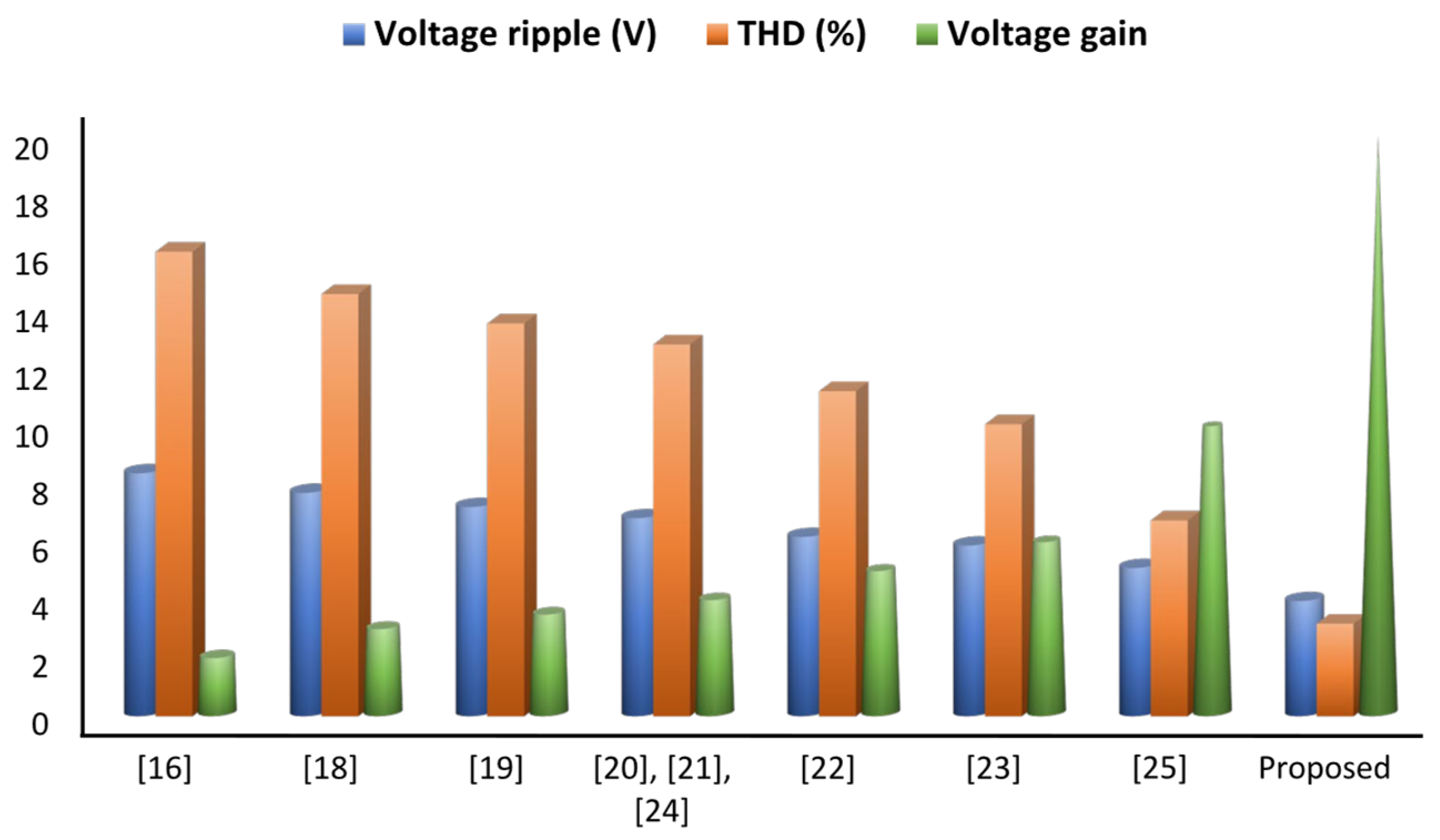
- Proposed a novel configuration of high gain interleaved DC-DC converter consisting of a voltage doubler circuit that can boost the output voltage of the fuel cell to almost 20 times in nominal circumstances.
- The proposed converter can achieve high voltage gain without using any transformer and can operate with a small duty cycle ratio, ensuring reduced switching losses and voltage/current ripple. Moreover, it persists with a maximum switching voltage stress of almost 50% of the output voltage and a maximum the diode voltage stress of nearly 25% of the output voltage.
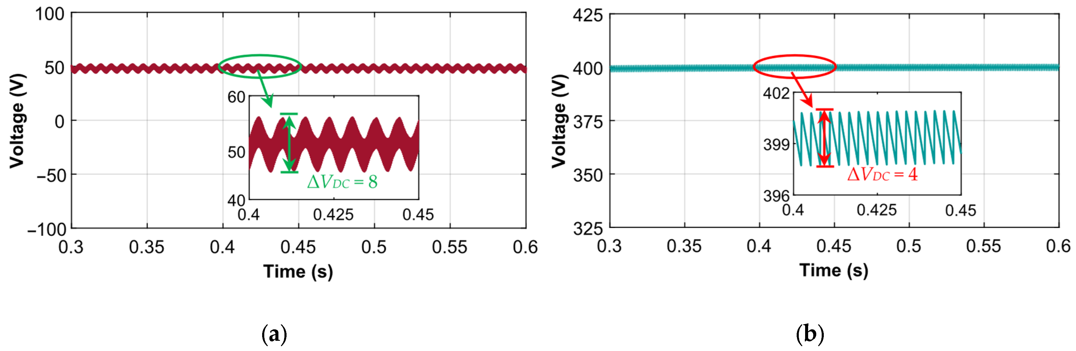
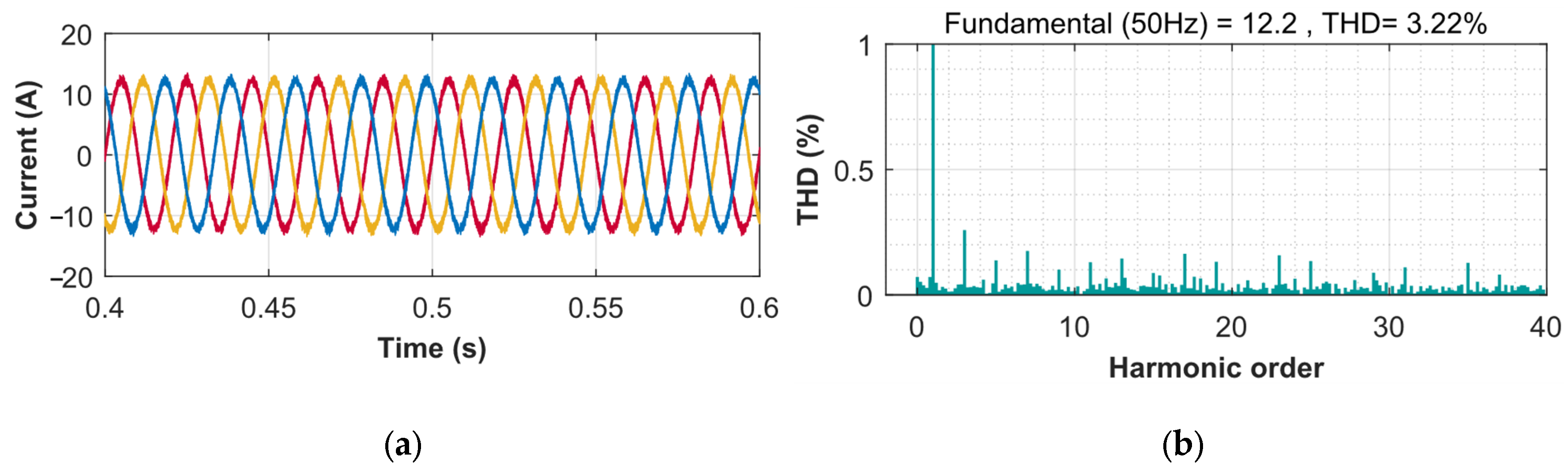
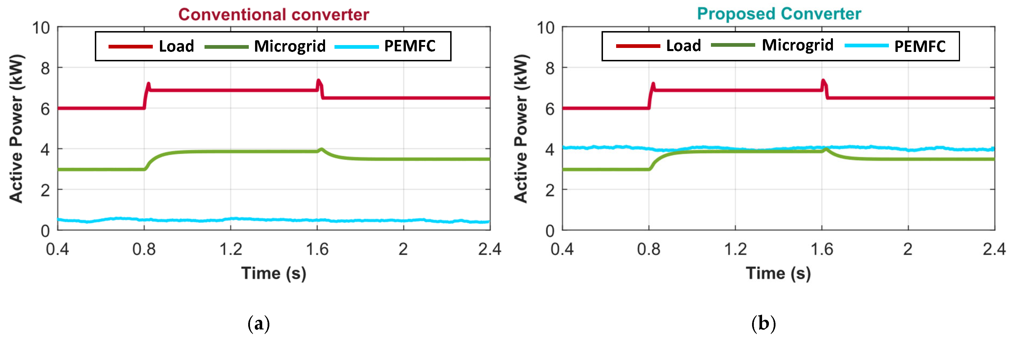
- Integration of the proposed converter with PEMFC allowed the microgrid to reduce the current harmonics (THD) to 3.22% along with minimal voltage ripple of 4V. Furthermore, integration properly managed the power requirements of the electrical loads, ensuring an improvement of the system’s power factor.
- The mathematical model and the results of the system are extensively analyzed, compared, and verified using proper simulation and hardware results.
2. High Gain Interleaved DC-DC Converter
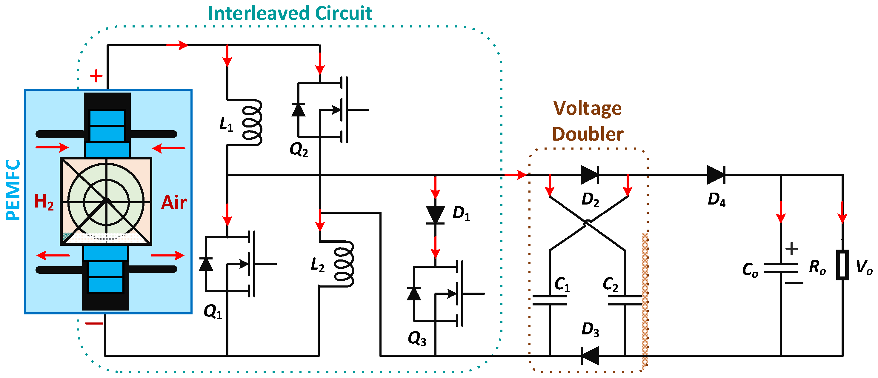
2.1. Circuit Configuration
2.2. Circuit Operation
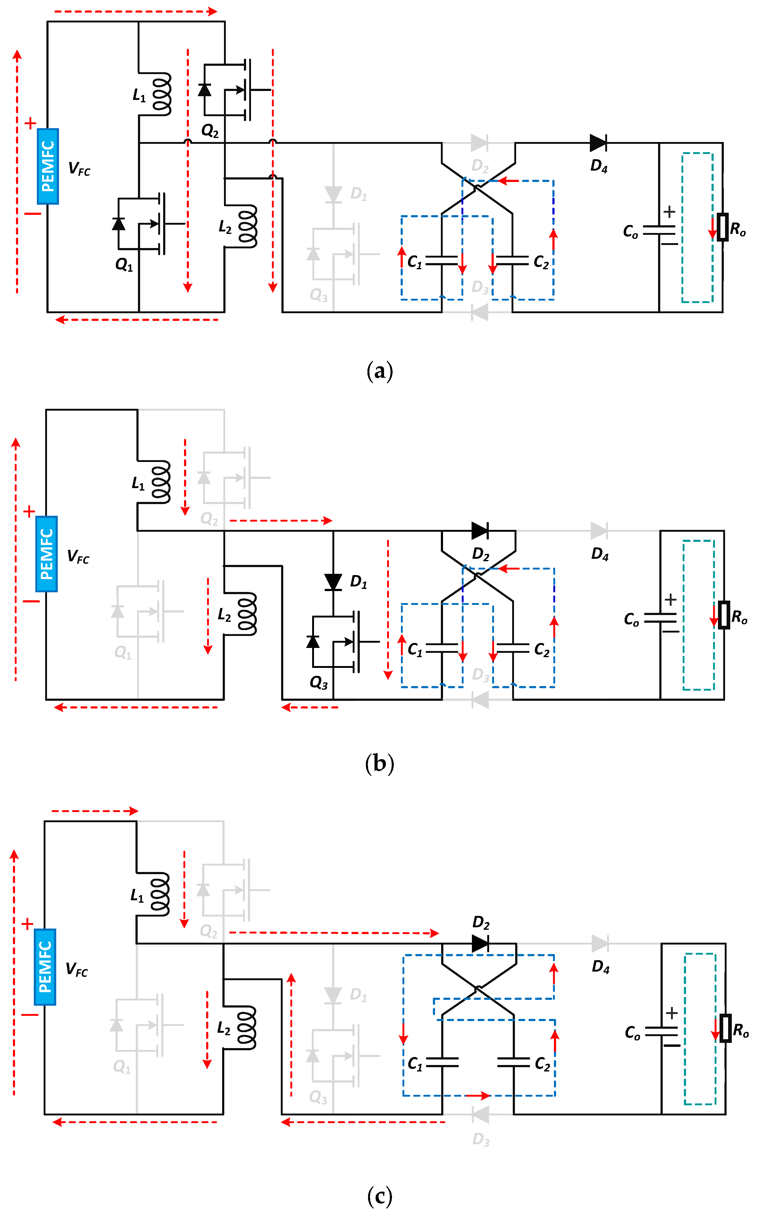
2.2.1. Mode 1

2.2.2. Mode 2
2.2.3. Mode 3
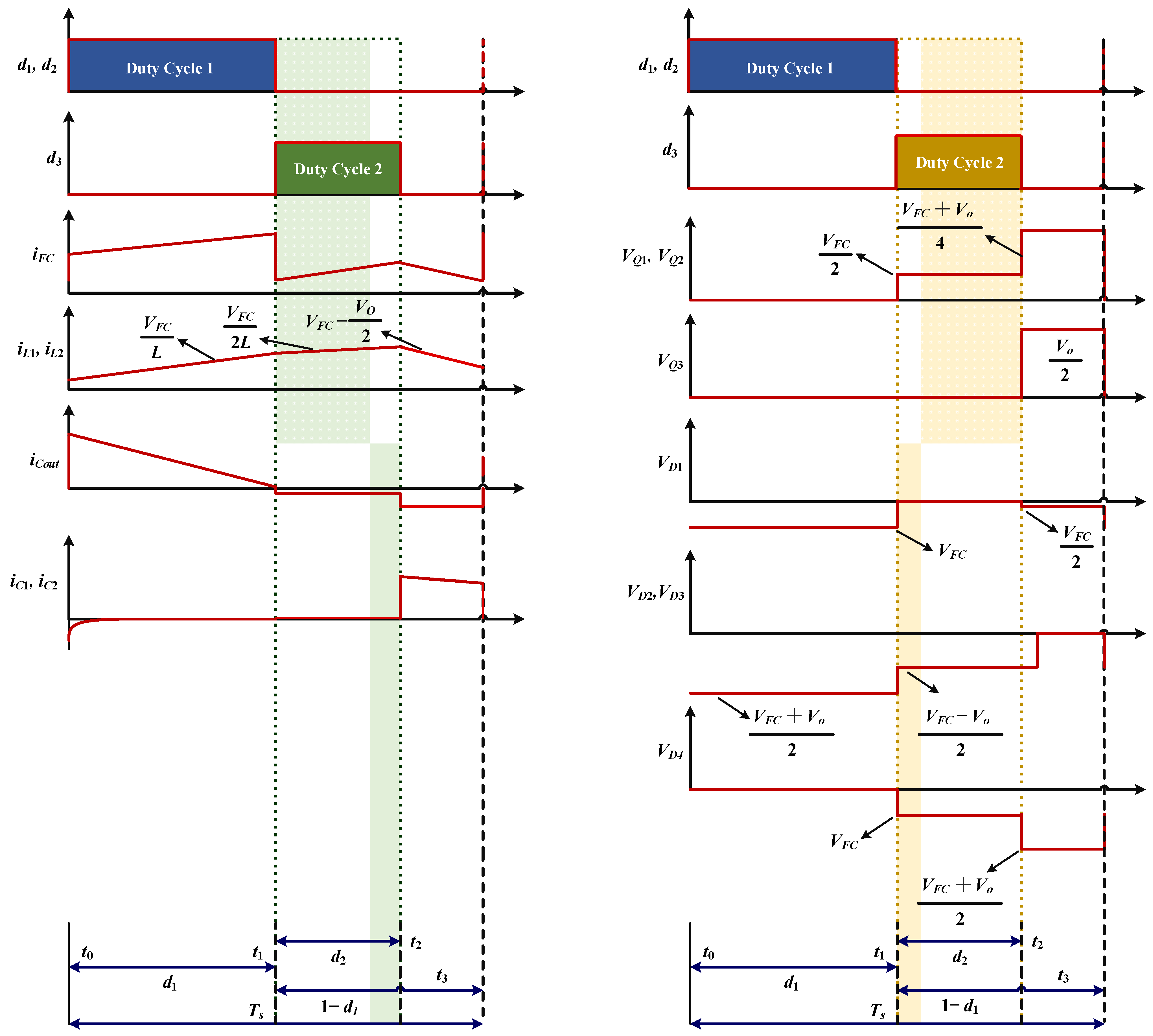
2.3. Mathematical Modelling
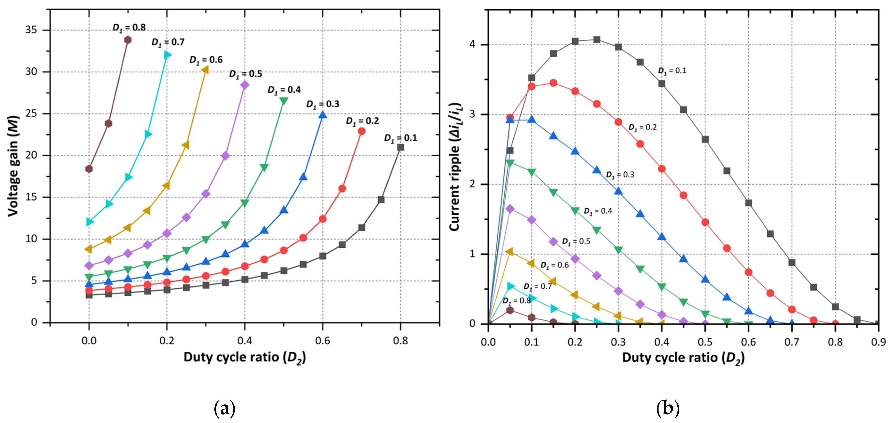
2.3.1. Voltage Gain Calculation
2.3.2. Current Ripple Calculation
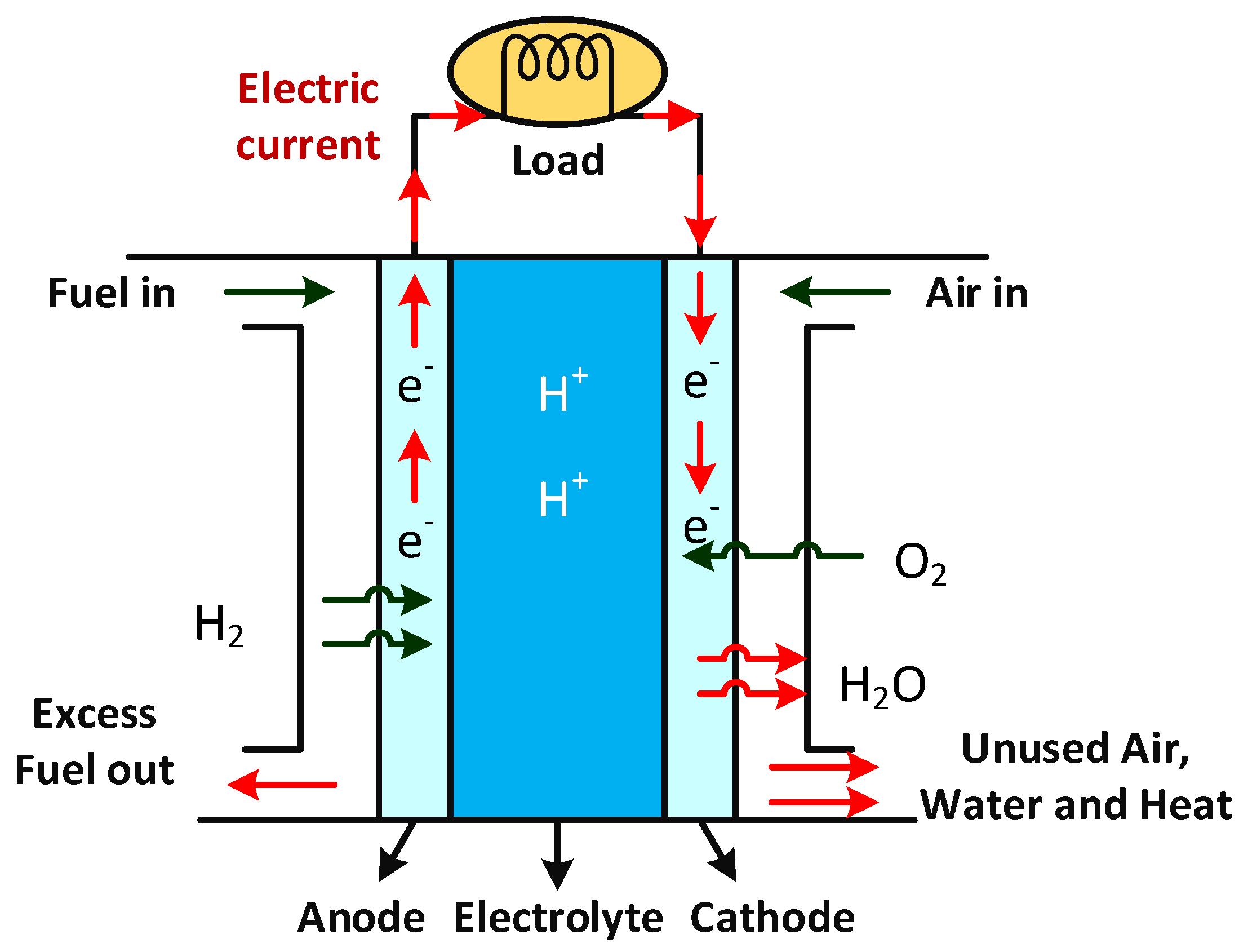
3. Proton Exchange Membrane Fuel Cell (PEMFC)
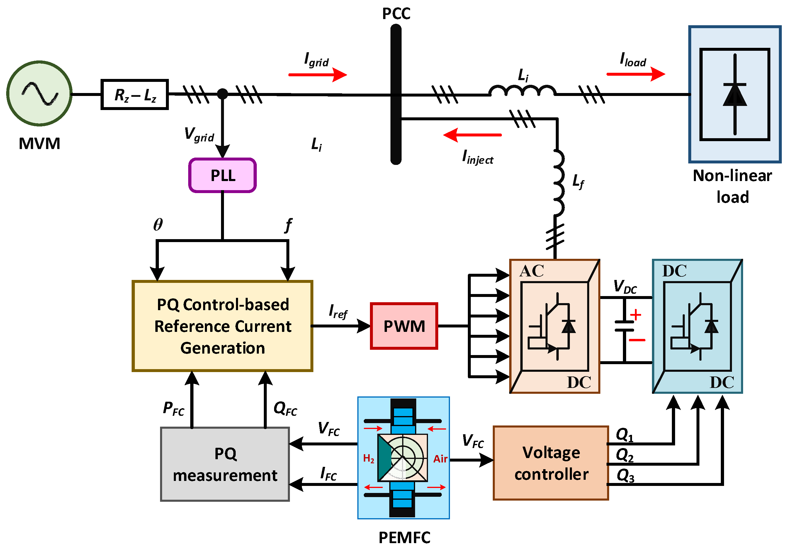
4. PEMFC Integrated Microgrid
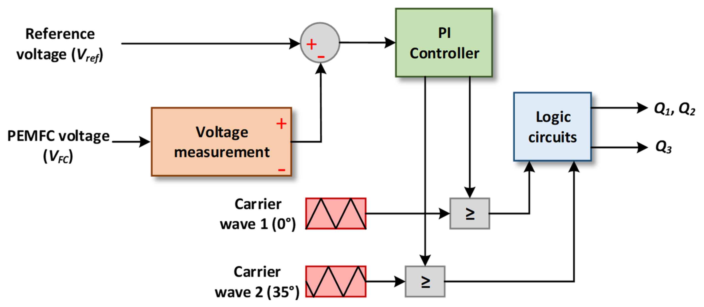
4.1. Control of the Proposed DC-DC Converter
4.2. Control of the DC-AC Inverter
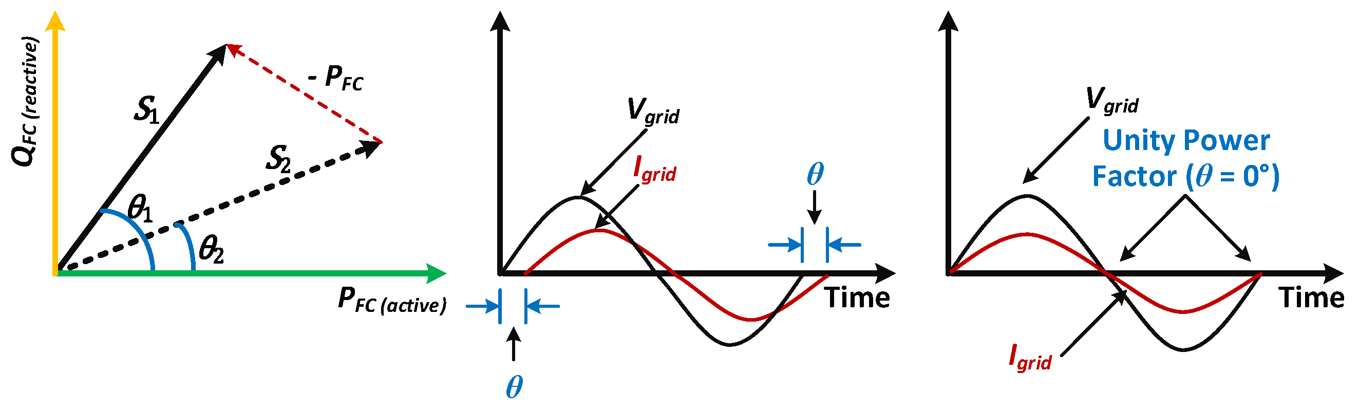
4.3. Active/Reactive Power Management
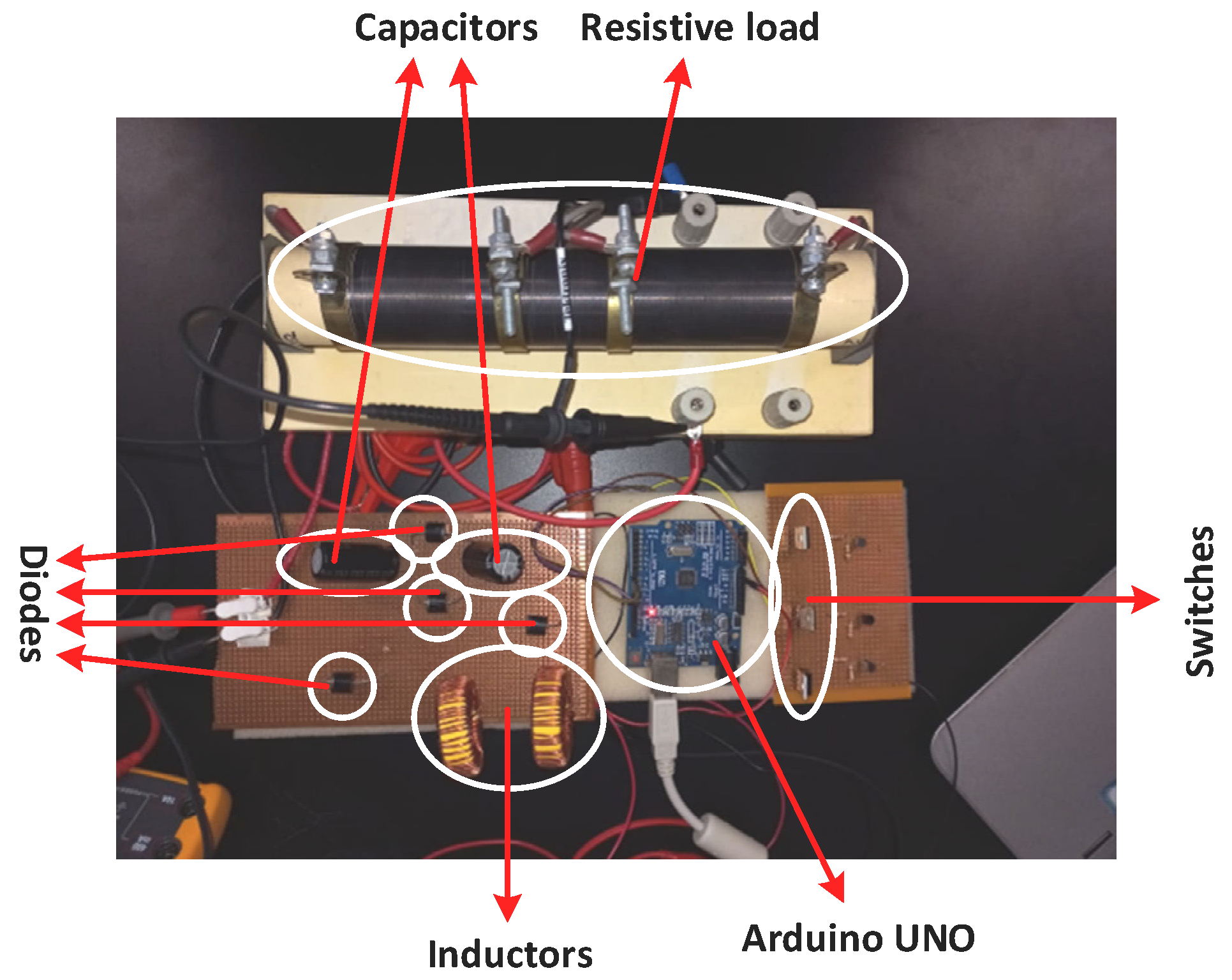
5. Result and Discussion
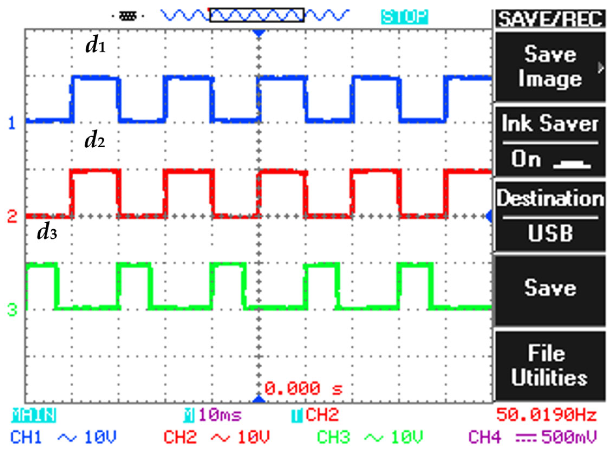
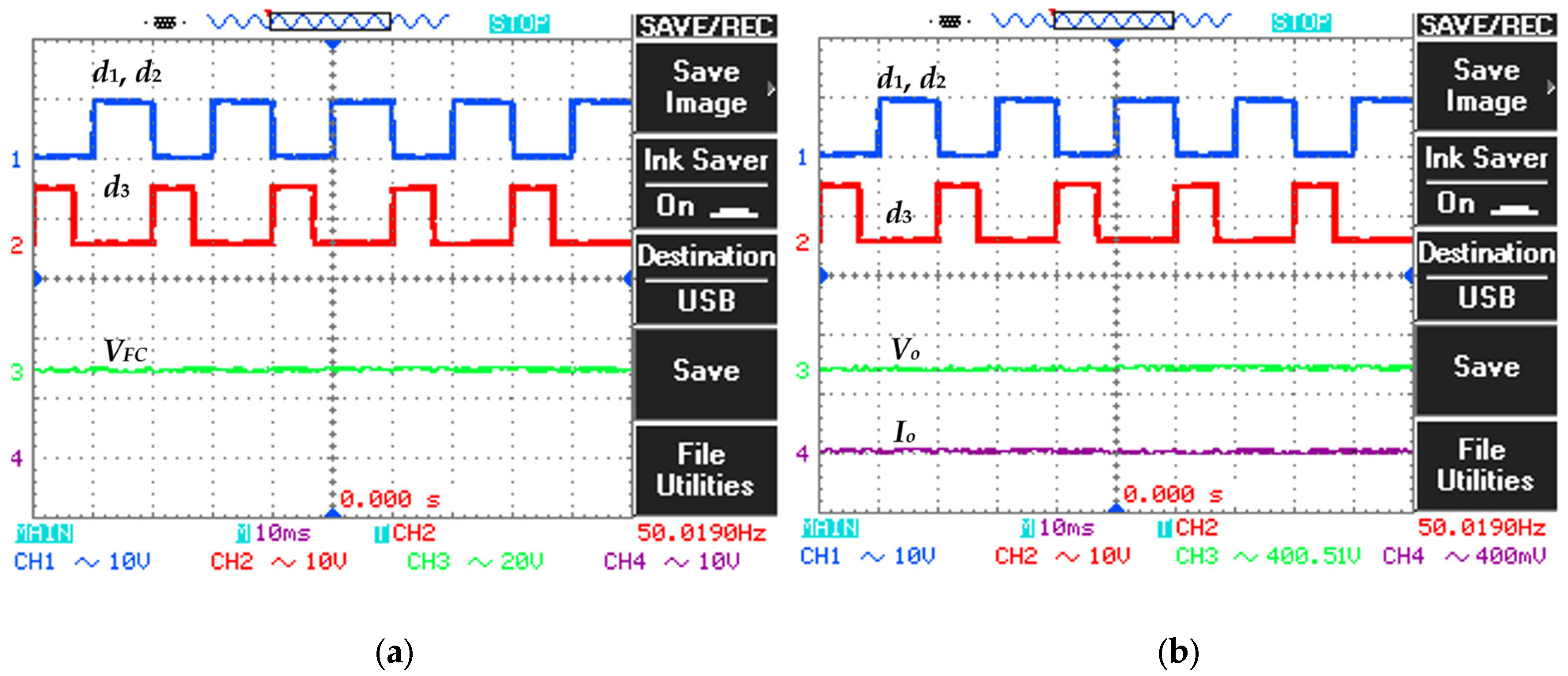
5.1. Performance of The Proposed DC-DC Converter
5.2. Performance of The PEMFC Integrated Microgrid
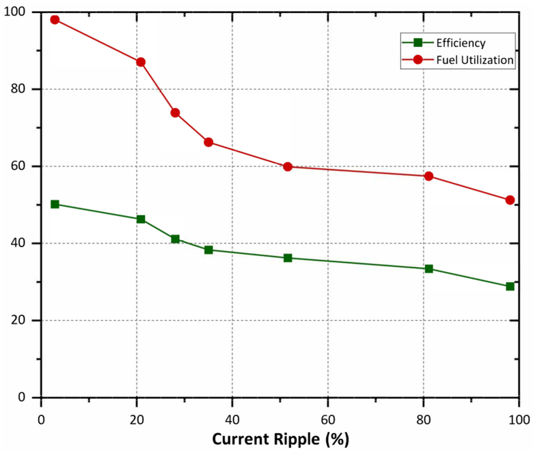
5.3. Performance Asssessment of the PEMFC
6. Conclusions
Author Contributions
Funding
Institutional Review Board Statement
Informed Consent Statement
Data Availability Statement
Acknowledgments
Conflicts of Interest
References
- Chakraborty, S.; Dash, S.K.; Elavarasan, R.M.; Kaur, A.; Elangovan, D.; Meraj, S.T.; Kasinathan, P.; Said, Z. Hydrogen Energy as Future of Sustainable Mobility. Front. Energy Res. 2022, 10. [Google Scholar] [CrossRef]
- İnci, M.; Türksoy, Ö. Review of fuel cells to grid interface: Configurations, technical challenges and trends. J. Clean. Prod. 2019, 213, 1353–1370. [Google Scholar] [CrossRef]
- Kalchschmid, V.; Erhart, V.; Angerer, K.; Roth, S.; Hohmann, A. Decentral Production of Green Hydrogen for Energy Systems: An Economically and Environmentally Viable Solution for Surplus Self-Generated Energy in Manufacturing Companies? Sustainability 2023, 15, 2994. [Google Scholar] [CrossRef]
- Meraj, S.T.; Yahaya, N.Z.; Hasan, K.; Lipu, M.H.; Elavarasan, R.M.; Hussain, A.; Hannan, M.A.; Muttaqi, K.M. A filter less improved control scheme for active/reactive energy management in fuel cell integrated grid system with harmonic reduction ability. Appl. Energy 2022, 312, 118784–118801. [Google Scholar] [CrossRef]
- Mansouri, S.A.; Jordehi, A.R.; Marzband, M.; Tostado-Véliz, M.; Jurado, F.; Aguado, J.A. An IoT-enabled hierarchical decentralized framework for multi-energy microgrids market management in the presence of smart prosumers using a deep learning-based forecaster. Appl. Energy 2023, 333, 120560. [Google Scholar] [CrossRef]
- Mansouri, S.A.; Ahmarinejad, A.; Sheidaei, F.; Javadi, M.S.; Jordehi, A.R.; Nezhad, A.E.; Catalao, J.P. A multi-stage joint planning and operation model for energy hubs considering integrated demand response programs. Int. J. Electr. Power Energy Syst. 2022, 140, 108103. [Google Scholar] [CrossRef]
- Shen, Q.; Hou, M.; Yan, X.; Liang, D.; Zang, Z.; Hao, L.; Shao, Z.; Hou, Z.; Ming, P.; Yi, B. The voltage characteristics of proton exchange membrane fuel cell (PEMFC) under steady and transient states. J. Power Sources 2008, 179, 292–296. [Google Scholar] [CrossRef]
- Bizon, N.; Thounthong, P. Real-time strategies to optimize the fueling of the fuel cell hybrid power source: A review of issues, challenges and a new approach. Renew. Sustain. Energy Rev. 2018, 91, 1089–1102. [Google Scholar] [CrossRef]
- Meraj, S.T.; Abd Rahman, M.S.; Yahaya, N.Z.; Ker, P.J.; Hossain, T.M.; Lipu, M.H.; Muttaqi, K.M.; Hannan, M.A. A Pencil Shaped 9-Level Multilevel Inverter with Voltage Boosting Ability: Configuration and Experimental Investigation. IEEE Access 2022, 10, 111310–111321. [Google Scholar] [CrossRef]
- Meraj, S.T.; Yu, S.S.; Rahman, M.S.; Hasan, K.; Lipu, M.S.H.; Trinh, H. Energy management schemes, challenges and impacts of emerging inverter technology for renewable energy integration towards grid decarbonization. J. Clean. Prod. 2023, 405, 137002–137034. [Google Scholar] [CrossRef]
- Kabalo, M.; Blunier, B.; Bouquain, D.; Miraoui, A. State-of-the-Art of DC-DC Converters for Fuel Cell Vehicles. In Proceedings of the IEEE Vehicle Power and Propulsion Conference, VPPC 2010, Lille, France, 1–3 September 2010; pp. 1–6. [Google Scholar]
- Overview. Step-Up DC—DC Converters: A Comprehensive Review of Voltage-Boosting Techniques. IEEE Trans. Power Electron. 2017, 32, 9143–9178. [CrossRef]
- Solsona, J.A.; Jorge, S.G.; Busada, C.A. Modeling and Nonlinear Control of DC-DC Converters for Microgrid Applications. Sustainability 2022, 14, 16889. [Google Scholar] [CrossRef]
- Kummara, V.G.R.; Zeb, K.; Muthusamy, A.; Krishna, T.N.V.; Kumar, S.V.P.; Kim, D.-H.; Kim, M.-S.; Cho, H.-G.; Kim, H.-J. A comprehensive review of DC–DC converter topologies and modulation strategies with recent advances in solar photovoltaic systems. Electronics 2020, 9, 31. [Google Scholar] [CrossRef]
- Hossain, M.Z.; Rahim, N.A. Recent progress and development on power DC-DC converter topology, control, design and applications: A review. Renew. Sustain. Energy Rev. 2018, 81, 205–230. [Google Scholar] [CrossRef]
- Gao, D.; Jin, Z.; Liu, J.; Ouyang, M. An interleaved step-up/step-down converter for fuel cell vehicle applications. Int. J. Hydrog. Energy 2016, 41, 22422–22432. [Google Scholar] [CrossRef]
- Mansouri, S.A.; Ahmarinejad, A.; Nematbakhsh, E.; Javadi, M.S.; Jordehi, A.R.; Catalao, J.P.S. Energy hub design in the presence of P2G system considering the variable efficiencies of gas-fired converters. In Proceedings of the SEST 2021—4th International Conference on Smart Energy Systems and Technology, Vaasa, Finland, 6–8 September 2021. [Google Scholar] [CrossRef]
- Thounthong, P.; Davat, B. Study of a multiphase interleaved step-up converter for fuel cell high power applications. Energy Convers. Manag. 2010, 51, 826–832. [Google Scholar] [CrossRef]
- Huangfu, Y.; Zhuo, S.; Chen, F.; Pang, S.; Zhao, D.; Gao, F. Robust Voltage Control of Floating Interleaved Boost Converter for Fuel Cell Systems. IEEE Trans. Ind. Appl. 2018, 54, 665–674. [Google Scholar] [CrossRef]
- Wang, P.; Zhou, L.; Zhang, Y.; Li, J.; Sumner, M. Input-Parallel Output-Series DC-DC Boost Converter with a Wide Input Voltage Range, for Fuel Cell Vehicles. IEEE Trans. Veh. Technol. 2017, 66, 7771–7781. [Google Scholar] [CrossRef]
- Wu, J.C.; Der Wu, K.; Jou, H.L.; Wu, Z.H.; Chang, S.K. Novel power electronic interface for grid-connected fuel cell power generation system. Energy Convers. Manag. 2013, 71, 227–234. [Google Scholar] [CrossRef]
- Wu, Y.; Huangfu, Y.; Ma, R.; Ravey, A.; Chrenko, D. A strong robust DC-DC converter of all-digital high-order sliding mode control for fuel cell power applications. J. Power Sources 2018, 413, 222–232. [Google Scholar] [CrossRef]
- Pires, V.F.; Cordeiro, A.; Foito, D.; Silva, J.F. High step-up DC-DC converter for fuel cell vehicles based on merged quadratic boost-Cuk. IEEE Trans. Veh. Technol. 2019, 68, 7521–7530. [Google Scholar] [CrossRef]
- Elsayad, N.; Moradisizkoohi, H.; Mohammed, O.A. A Single-Switch Transformerless DC-DC Converter with Universal Input Voltage for Fuel Cell Vehicles: Analysis and Design. IEEE Trans. Veh. Technol. 2019, 68, 4537–4549. [Google Scholar] [CrossRef]
- Bi, H.; Wang, P.; Che, Y. A capacitor clamped H-Type Boost DC-DC converter with wide voltage-gain range for fuel cell vehicles. IEEE Trans. Veh. Technol. 2019, 68, 276–290. [Google Scholar] [CrossRef]
- Khan, S.; Mahmood, A.; Zaid, M.; Tariq, M.; Sadaf, S. A Single Inductor, Single Switch High Gain DC-DC Boost Converter. In Proceedings of the IEEE International Women in Engineering (WIE) Conference on Electrical and Computer Engineering (WIECON-ECE 2020), Bhubaneswar, India, 26–27 December 2020; pp. 98–101. [Google Scholar] [CrossRef]
- Khan, S.; Mahmood, A.; Zaid, M.; Tariq, M.; Lin, C.H.; Ahmad, J.; Alamri, B.; Alahmadi, A. A High Step-up DC-DC Converter Based on the Voltage Lift Technique for Renewable Energy Applications. Sustainability 2021, 13, 11059. [Google Scholar] [CrossRef]
- Khan, S.; Mahmood, A.; Tariq, M.; Zaid, M.; Khan, I.; Rahman, S. Improved Dual Switch Non-Isolated High Gain Boost Converter for DC microgrid Application. In Proceedings of the 2021 IEEE Texas Power and Energy Conference (TPEC), College Station, TX, USA, 2–5 February 2021. [Google Scholar] [CrossRef]
- Huangfu, Y.; Ma, Y.; Bai, H.; Xu, L.; Wang, A.; Ma, R. A family of high gain fuel cell front-end converters with low input current ripple for PEMFC power conditioning systems. Int. J. Hydrog. Energy 2021, 46, 27156–27172. [Google Scholar] [CrossRef]
- Mahmood, A.; Zaid, M.; Ahmad, J.; Khan, M.A.; Khan, S.; Sifat, Z.; Lin, C.-H.; Sarwar, A.; Tariq, M.; Alamri, B. A Non-Inverting High Gain DC-DC Converter with Continuous Input Current. IEEE Access 2021, 9, 54710–54721. [Google Scholar] [CrossRef]
- Schmitz, L.; Martins, D.C.; Coelho, R.F. Comprehensive conception of high step-Up DC-DC converters with coupled inductor and voltage multipliers techniques. IEEE Trans. Circuits Syst. I Regul. Pap. 2020, 67, 2140–2151. [Google Scholar] [CrossRef]
- Zhang, D.; Yang, Y.; Fang, J.; Alkhayyat, A. An optimal methodology for optimal controlling of a PEMFC connected to the grid based on amended penguin optimization algorithm. Sustain. Energy Technol. Assess. 2022, 53, 102401. [Google Scholar] [CrossRef]
- Schumann, M.; Cosse, C.; Becker, D.; Vorwerk, D.; Schulz, D. Modeling and experimental parameterization of an electrically controllable PEM fuel cell. Int. J. Hydrog. Energy 2021, 46, 28734–28747. [Google Scholar] [CrossRef]
- Priya, M.; Ponnambalam, P. Circulating Current Control of Phase-Shifted Carrier-Based Modular Multilevel Converter Fed by Fuel Cell Employing Fuzzy Logic Control Technique. Energies 2022, 15, 6008. [Google Scholar] [CrossRef]
- Dhimish, M.; Vieira, R.G.; Badran, G. Investigating the stability and degradation of hydrogen PEM fuel cell. Int. J. Hydrog. Energy 2021, 46, 37017–37028. [Google Scholar] [CrossRef]
- Li, M.; Liu, H.; Yan, M.; Xu, H.; He, H. A Novel Multi-Objective Energy Management Strategy for Fuel Cell Buses Quantifying Fuel Cell Degradation as Operating Cost. Sustainability 2022, 14, 16190. [Google Scholar] [CrossRef]
- Hasan, K.; Meraj, S.T.; Othman, M.M.; Lipu, M.S.H.; Hannan, M.A.; Muttaqi, K.M. Savitzky–Golay Filter-Based PLL: Modeling and Performance Validation. IEEE Trans. Instrum. Meas. 2022, 71, 1–6. [Google Scholar] [CrossRef]
- Afonso, J.; Couto, C.; Martins, J. Active Filters with Control Based on the p-q Theory. IEEE Ind. Electron. Soc. Newsl. 2000, 47, 5–10. Available online: https://www.researchgate.net/publication/251506378 (accessed on 20 February 2023).
- Rahimi-Esbo, M.; Sangtabi, A.R.; Alizadeh, E. Manifold Design in a PEM Fuel Cell Stack to Improve Flow Distribution Uniformity. Sustainability 2022, 14, 15702. [Google Scholar] [CrossRef]


| Parameters | Values |
|---|---|
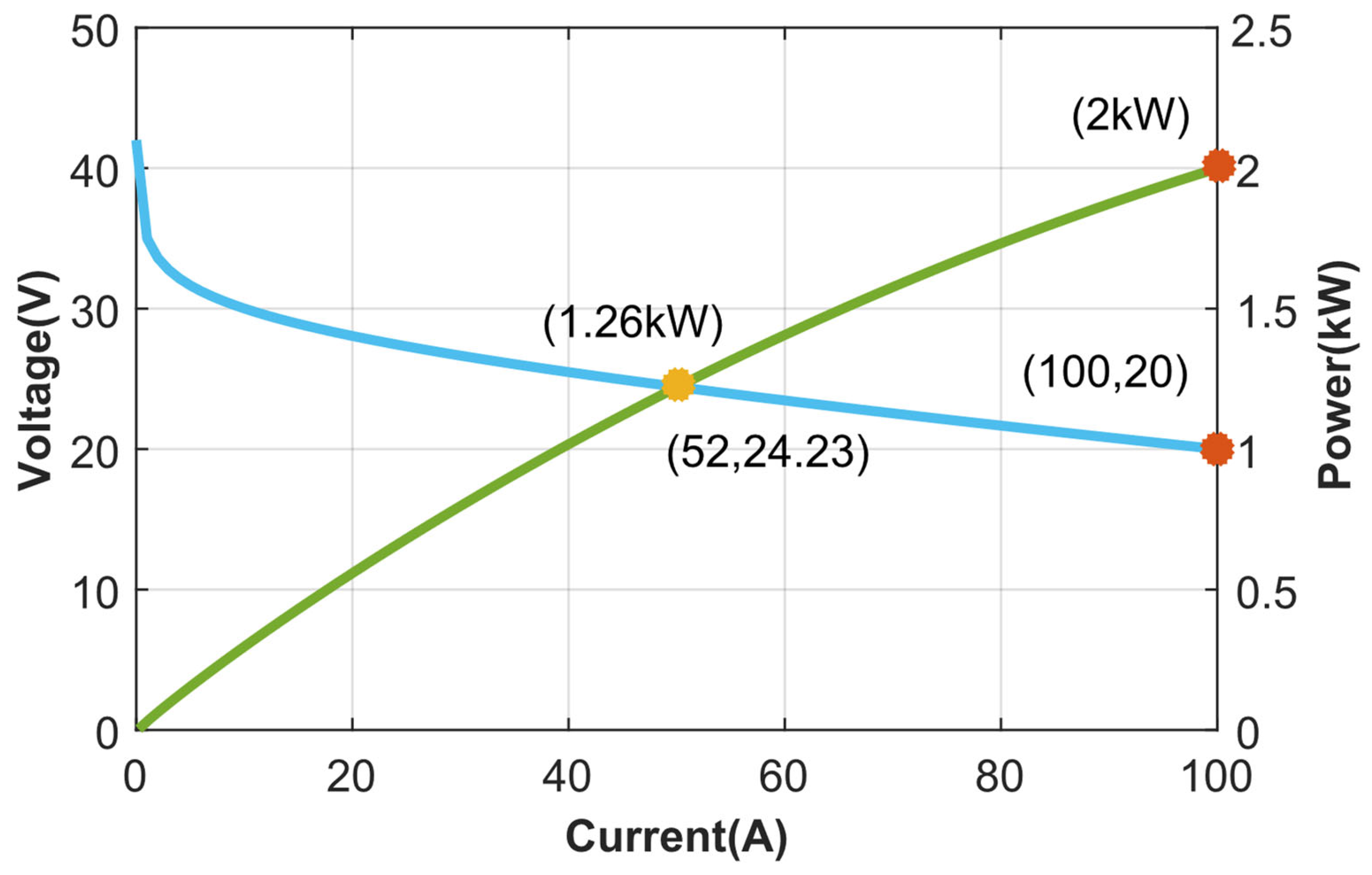
| Open Circuit Voltage | 42 V |
| Nominal voltage | 24.3 V |
| Maximum voltage | 20 V |
| Nominal current | 52 A |
| Maximum current | 100 A |
| Exchange current | 0.027 A |
| Nominal power | 1.26 kW |
| Maximum power | 2 kW |
| Number of cells | 42 |
| Nominal stack efficiency | 46% |
| Operating temperature | 55 °C |
| Nominal air flow rate | 2400 lpm |
| Maximum air flow rate | 4615 lpm |
| Internal resistance | 0.06 Ω |
| Activation coefficient | 0.308 |
| Parameters | Symbols | Values |
|---|---|---|
| Grid voltage | Vgrid | 400 V |
| Grid current | Igrid | 13 A |
| Active power | Pgrid | 5.2 kW |
| Passive filter | Lf | 5 mH |
| Line inductance | Lind | 1 mH |
| Non-linear load | R–L | 50 Ω–5 mH |
| PI controller | kp, ki | 0.001, 0.01 |
| Reference voltage | Vref | 400 V |
| Fundamental frequency | f | 50 Hz |
| Switching frequency | fsw | 25 kHz |
| Impedance | Rz–Lz | 10 Ω–1 mH |
| Parameters | Ratings (Units) |
|---|---|
| Rated Power | 160 W |
| Source Voltage | 20 V |
| Output Voltage | 400 V |
| Duty Cycle Ratio (D1) | 50% |
| Duty Cycle Ratio (D2) | 35% |
| Switching Frequency (fsw) | 25 kHz |
| Inductors (LX, LY) | 120 μH |
| Capacitor (C1, C2, Co) | 100 μF |
| Switches (SX, SY, SZ) | FDP20N40 |
| Diodes (D1, D2, D3, D4) | SBR20A200CTB |
| System | Loads (R–L) | Switching Time (s) | Microgrid (kW) | PEMFC (kW) | Load Demand (kW) | Injected Power Capability (kW) | Power Factor |
|---|---|---|---|---|---|---|---|
| Conventional | 5.5 Ω–3.6 mH | t < 0.8 | 2.79 | 0.5 | 6.03 | 2.84 | 0.53 |
| 3.5 Ω–5.5 mH | 0.8 < t < 1.6 | 3.72 | 6.86 | 3.77 | 0.55 | ||
| 4.5–5 mH | t > 1.6 | 3.34 | 6.44 | 3.39 | 0.53 | ||
| Proposed | 5.5 Ω–3.6 mH | t < 0.8 | 2.79 | 4 | 6.03 | 6.79 | 0.99 |
| 3.5 Ω–5.5 mH | 0.8 < t < 1.6 | 3.72 | 6.86 | 7.72 | 0.99 | ||
| 4.5–5 mH | t > 1.6 | 3.34 | 6.44 | 7.34 | 0.99 |
Disclaimer/Publisher’s Note: The statements, opinions and data contained in all publications are solely those of the individual author(s) and contributor(s) and not of MDPI and/or the editor(s). MDPI and/or the editor(s) disclaim responsibility for any injury to people or property resulting from any ideas, methods, instructions or products referred to in the content. |
© 2023 by the authors. Licensee MDPI, Basel, Switzerland. This article is an open access article distributed under the terms and conditions of the Creative Commons Attribution (CC BY) license (https://creativecommons.org/licenses/by/4.0/).
Share and Cite
Mumtaz, F.; Yahaya, N.Z.; Meraj, S.T.; Singh, N.S.S.; Rahman, M.S.; Hossain Lipu, M.S. A High Voltage Gain Interleaved DC-DC Converter Integrated Fuel Cell for Power Quality Enhancement of Microgrid. Sustainability 2023, 15, 7157. https://doi.org/10.3390/su15097157
Mumtaz F, Yahaya NZ, Meraj ST, Singh NSS, Rahman MS, Hossain Lipu MS. A High Voltage Gain Interleaved DC-DC Converter Integrated Fuel Cell for Power Quality Enhancement of Microgrid. Sustainability. 2023; 15(9):7157. https://doi.org/10.3390/su15097157
Chicago/Turabian StyleMumtaz, Farhan, Nor Zaihar Yahaya, Sheikh Tanzim Meraj, Narinderjit Singh Sawaran Singh, Md. Siddikur Rahman, and Molla Shahadat Hossain Lipu. 2023. "A High Voltage Gain Interleaved DC-DC Converter Integrated Fuel Cell for Power Quality Enhancement of Microgrid" Sustainability 15, no. 9: 7157. https://doi.org/10.3390/su15097157
APA StyleMumtaz, F., Yahaya, N. Z., Meraj, S. T., Singh, N. S. S., Rahman, M. S., & Hossain Lipu, M. S. (2023). A High Voltage Gain Interleaved DC-DC Converter Integrated Fuel Cell for Power Quality Enhancement of Microgrid. Sustainability, 15(9), 7157. https://doi.org/10.3390/su15097157