Article

Design Criteria for the Construction of Energy Storage Salt Cavern Considering Economic Benefits and Resource Utilization

1
School of Health Economics and Management, Nanjing University of Chinese Medicine, Nanjing 210023, China
2
Institute of Geotechnical Engineering, Zhejiang University, Hangzhou 310058, China
3
MOE Key Laboratory of Soft Soils and Geoenvironmental Engineering, Zhejiang University, Hangzhou 310058, China
*
Author to whom correspondence should be addressed.
Sustainability 2023, 15(8), 6870; https://doi.org/10.3390/su15086870
Submission received: 27 March 2023 / Revised: 14 April 2023 / Accepted: 15 April 2023 / Published: 19 April 2023
(This article belongs to the Topic Energy Storage Using Underground Mine Space)

Abstract

:
Underground salt caverns have been widely used for oil and gas storage and have attracted increasing attention. The construction design of salt caverns is directly related to the final storage capacity, economic benefits, and resource utilization. However, due to the numerous combinations of multi-stage process parameters involved in the construction design, it is difficult to optimize them individually through indoor experiments and numerical simulations. In this regard, this paper attempts to put forward the basic principles of cavern construction design criteria with economic benefits and resource utilization as indicators. Firstly, 1258 groups of cavern construction process parameters were randomly generated under certain basic rules, including inner tube depth, outer tube depth, oil pad depth, duration, and water injection flow rate, for five direct leaching stages. Then, the cavern capacity, economic benefit, and rock salt resource utilization corresponding to these process parameters were obtained through batch processing using single-well salt cavern leaching simulation software (SSCLS). Finally, the influence laws of the distance between the inner tube and oil pad and lifting heights, and the rates of the inner tube and oil pad on the expected economic benefits and salt resource utilization, are discussed. In the actual project, it is recommended to increase the distance between the inner tube and the oil pad, increase the ratio of oil pad lifting height to duration, and use the appropriate lifting height to obtain greater expected revenue and resource utilization. This work will improve the efficiency and scientificity of cavern construction design, which is of great significance in guiding the construction and design for energy storage in salt caverns.

1. Introduction

1.1. Construction Requirements and Process of Rock Salt Storage

In recent years, underground salt caverns have been widely used in oil, gas, and compressed air energy storage [1], which have attracted increasing attention [2,3]. In 2020, more than 90% of the U.S. strategic petroleum reserve was in the Texas and Louisiana rock salt reservoirs, with a total storage capacity of 119 million tons [4,5]. At present, there are more than 90 underground rock salt gas storage locations in the world, with a total working gas volume of more than 28 billion cubic meters and a daily gas extraction volume of about 1.56 billion cubic meters; gas storage accounts for 23% of all storage types [6]. Rock salt storage reservoirs are generally located 1000–2000 m underground and are mainly constructed through water solution mining. Fresh water is injected into the deep rock salt strata through tubes, and the dissolved rock salt is brought to the surface with the brine discharge. After years of the injection–dissolution–discharge cycle, a cavern with a volume of 0.1–1 million cubic meters is gradually formed [6,7].
The process of water solution mining is shown in Figure 1. Fresh water is injected through the inner tubes and brine is discharged from the outer tubes, which is called the direct leaching mode, and vice versa [8]. In the single-well water solution mining process, two concentric casings must be drilled into the rock salt formation. The casing is a flow path for the solvent-resistant oil pad, usually using diesel fuel, which is used to protect the top of the rock salt formation from being dissolved. The construction of salt caverns is a moving boundary problem with large dimensions, long periods, and extremely complex convective mass transfer processes, and it is usually divided into several stages. Each stage requires the determination of a series of parameters, such as the depth of the inner tube, outer tube, and oil pad, and the water injection amount, which will affect the concentration and flow fields of the brine, change the dissolution rate at the boundary, and, ultimately, determine the cavern shape [8,9].

1.2. Importance of Construction Design and Shape Control

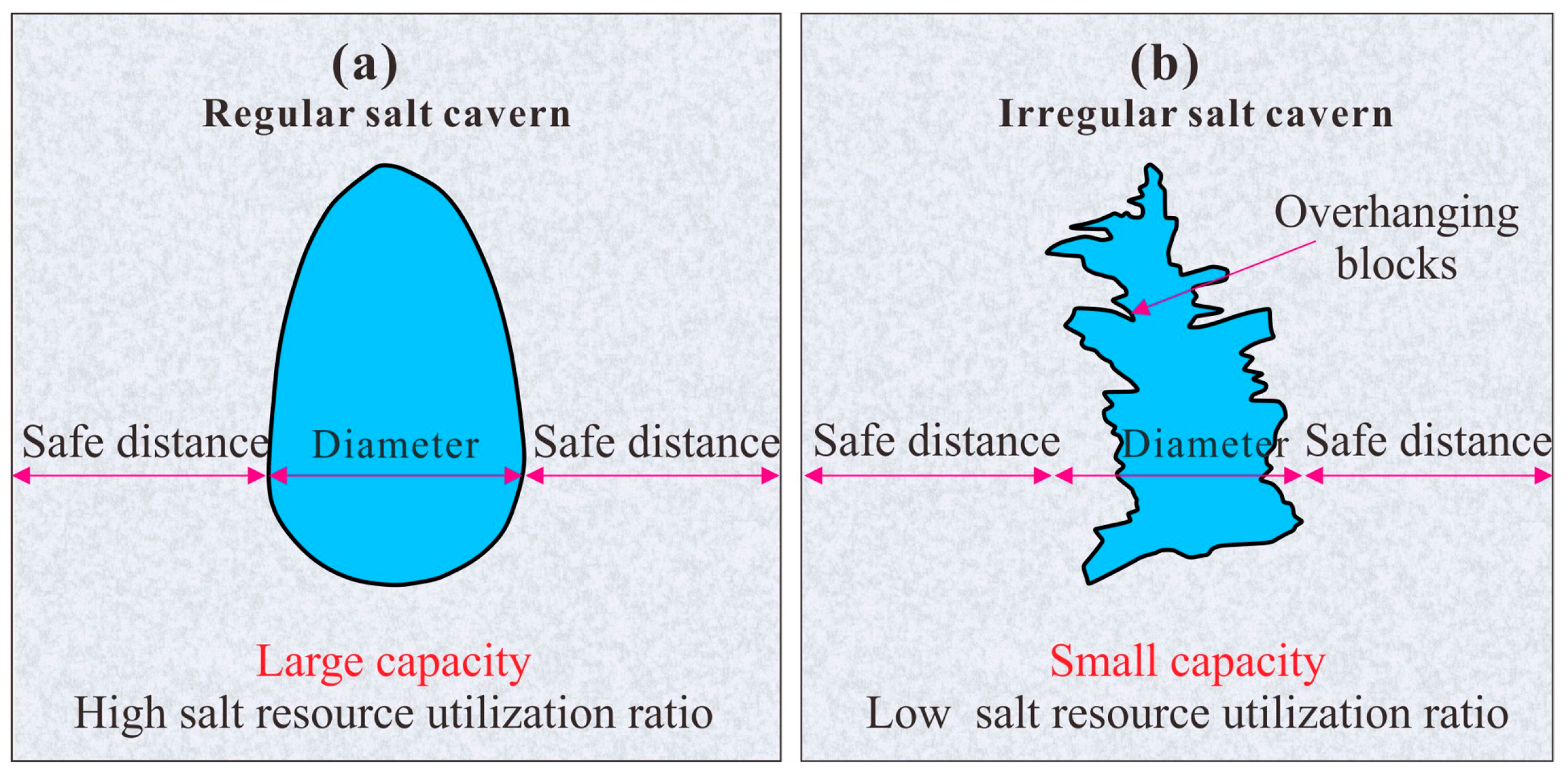
A regular and reasonable shape (e.g., an ellipsoid) is the key to ensuring storage capacity and long-term safety and stability. The rock salt resource occupied by the cavern includes the storage itself and the underground space occupied by the safe distance that must be maintained to keep the storage safe and stable. The ideal cavern design occupies less of the rock salt resources and obtains more storage capacity and more expected revenue. Usually, the ratio of storage capacity to occupied rock salt resources is adopted to measure rock salt resource utilization. In the actual cavern construction, there are significant differences between the actual cavern shape and the designed cavern shape due to the lack of strict control of the water solution mining process.
Different shapes of rock salt caverns are shown in Figure 2 [10]. The cavern shapes shown in Figure 2a,b occupies the same underground space and consumes the same rock salt resources. However, the storage capacity of the regular cavern shape is significantly larger compared to the irregular cavern shape, which implies more economic benefits and higher utilization of rock salt resources. Moreover, the overhanging blocks formed in the salt caverns may easily collapse and cause very serious economic losses and safety accidents [10,11,12]. Therefore, the construction design and shape control of the salt caverns play extremely important roles in energy storage. In general, the design and control should meet the requirements of having a regular and stable shape, large storage capacity, and high construction efficiency as much as possible [13].

1.3. Shortcomings of the Current Research

Most of the current research focuses on shape predictions, while there is a dearth of work on construction design and economic analysis [7,13]. Durie and Jessen summarized the relationship between the rock salt dissolution rate and the concentration, flow rate, interface angle, interface roughness, temperature, and other factors through rock salt dissolution experiments in the laboratory, and they obtained an empirical equation [14,15]. Kazemi, Reda, Liu, et al. investigated the flow patterns and laws of freshwater–brine buoyancy convection through jet experiments and proposed a simplified model of the non-constant, three-dimensional turbulent flow field in salt caverns [3,16,17]. Yang et al. discussed the effect of the initial velocity on the development pattern of the final flow field using physical simulation experiments and particle image velocimetry (PIV). They developed a simplified two-dimensional mathematical model for the buoyant jet [9].
In terms of simulation software, Li et al. and Xiao et al. simulated the dynamic dissolution process of two-dimensional salt caverns by directly solving the NS equation and the convective diffusion equation [10,18,19]. Saberian proposed a plume ascent model and prepared a water solution mining process model program—SALGAS, and the simulation results are in good agreement with the field data [20]. Kunstman and Urbanczyk proposed a gravitational equilibrium model, based on a program called “WinUbro”, which has since been developed and is widely used worldwide [21]. Li et al. developed the SSCLS program to improve shape prediction accuracy by considering the accumulation of insoluble substances at the bottom of salt caverns [8]. Wan et al. developed a new VC++ solver—TWHSMC, which can predict the salt cavern shape more accurately [22].
The laws for the cavern construction parameters that influence the water solution mining process and cavern shape are the basis for the construction design and parameter optimization of rock salt caverns. Wang et al. proposed the optimization of the leaching mode, oil pad height, and flow rate by analyzing the water solution mining process [23]. Wang et al. analyzed the site production data and provided suggestions to optimize the oil pad lifting height, inner and outer tube spacing, and water injection amount [24]. Li et al. predicted rock salt storage capacity through machine learning and optimized the construction parameters, such as the duration, inner tube depth, outer tube depth, and oil pad depth [6]. Xiao et al. discussed the effects of the water injection rate and direction in horizontal caverns on leaching efficiency, water-saving capacity, rock salt resource utilization, and cavern shape through numerical simulation [19]. Ren et al. studied the cavern volume expansion law at different injection flow rates and well spacings through model tests [25]. Based on the cavern construction simulation program, TWHSMC, Wan et al. discussed the effects of the water injection method, oil pad, and oil tube lifting method on the horizontal cavern construction process and salt cavern shape [26,27].
Although the cavern shape can be predicted through a combination of experiments in the laboratory and simulation software models, the construction design and parameter optimization of rock salt caverns require several iterations of process parameter adjustment based on experimental and simulation results. Due to the very large range of process parameters that can be adjusted and the interplay of results at different stages, this process is generally time-consuming and relies on extensive engineering experience. These current studies have provided optimization methods and schemes for cavern construction design. However, the data sources are very limited. Further, the laws regarding the key process parameters influencing storage economics and rock salt resource utilization have not been comprehensively summarized. Therefore, current research fails to provide effective references and improve the efficiency of cavern construction design and shape control.

1.4. The Research Purpose of This Paper

The purpose of this paper was to propose the basic principles of the design optimization of cavern construction parameters with consideration of the economic benefits and resource utilization serving as indicators. Firstly, 1258 groups of multi-stage construction parameters were randomly generated under certain base rules, including inner tube depth, outer tube depth, oil pad depth, duration, and the water injection flow rate, for five direct leaching stages. Then, the cavern construction results corresponding to these process parameters, including the final storage volume, expected revenue, and resource utilization rate, were obtained through batch processing using single-well salt cavern leaching simulation software (SSCLS). Finally, the laws influencing the effects of the inner tube and oil pad distance, the lifting height of the inner tube and oil pad, and the lifting rate on the expected revenue and resource utilization of rock salt storages are discussed, and corresponding design principles are proposed. This work will improve the efficiency and scientificity of cavern construction design, which is of great significance in guiding the construction and design of rock salt energy storage locations.

2. Data Acquisition

2.1. Cavern Construction Design Parameters

In this paper, the cavern construction process is temporarily taken as five direct leaching stages, as shown in Figure 3. During each stage, different design parameters were randomly generated. The randomly generated rules for each design parameter during each stage were as follows:
(1) The inner tube depths in the initial stage were all 0 m, and the depths of the outer tubes and oil pad were determined relative to that depth;
(2) The oil pad depths in the final stage were all 80 m to control the heights of the final cavern, which were all 80 m;
(3) The inner tube depth in each stage was lifted, in turn, and the height of each lift was not less than 5 m;
(4) The outer tube depth in each stage needed to be higher than the inner tube depth and 5 m lower than the oil pad depth;
(5) The oil pad depth in each stage was lifted, in turn, and the height of each lift was not less than 5 m;
(6) The duration during each cavern construction stage was a minimum of 30 days and a maximum of 200 days, for a total of 600 days across the five stages (approximately two years);
(7) The adjustment range of the flow rate and concentration of the injected water in the actual project was small. Therefore, the flow rate and concentration, during each stage, were taken as the common values in the current project. The flow rate of water injection was 60 m3/h and the concentration was 0 [6,28].
With the above rules, 1258 groups of randomly combined process parameters were finally generated, some of which are shown in Table 1. Each group contained 5 stages of inner tube depths, oil pad depths, and durations. For this paper, it was assumed that the insoluble substance content in the rock salt was constant, which was 10% in all cases, and the effect of the insoluble interlayer was not considered [6,7,8,29].

2.2. Expected Revenue and Resource Utilization

The cavern capacity, expected revenue, and resource utilization were obtained using our previously developed software for simulating the dynamic expansion of salt caverns, called “Single-well Salt Cavern Leaching Simulation (SSCLS)” [8]. In this software, formulas for calculating the radius of salt caverns, brine concentration, flow rate, salt cavern volume, and insoluble substance height were derived based on mass conservation and some reasonable assumptions. Further, a mathematical model for the expansion of the salt cavern boundary was established,
ρ s V c t ( 1 u ) + V d t C s Q V c t V d t C = ( V c C ) t
where ρ s is the density of rock salt, V c is the volume of the circulation zone, u is the content of insoluble in the salt, V d is the volume of the dead zone under the inner tube, C s is the saturated concentration of brine, Q is the flow of the injected water, C is brine concentration in the circulation, and t is time.
Based on the particle accumulation theory, the redistribution equation of the insoluble substance was derived, and the mathematical model of the insoluble substance surface was established.
z t = ( R , Θ , H ) P r , θ , z U R , Θ , H V R , Θ , H π [ D ( H z ) ] 2 t + d z r , θ + d z r , θ
where r , θ , z are spatial coordinates in the column coordinate system; U R , Θ , H is the in soluble content of the micro-element on point (R, Θ, H); D is the scattering coefficient between the maximum distance from the position of a fallen insoluble particle to the projection of its starting point on the cavern bottom and the height of the falling path of the insoluble particle; and V R , Θ , H t is the volume variation in the micro-element on point (R, Θ, H).
The state variables, governing equations, initial conditions, and boundary conditions for this numerical model have been described in detail in the references [8]. The VC++ program was written using the finite difference method. Here, after determining the initial values of the design parameters, the boundary extension of salt caverns, the brine concentration, and the surface of the insoluble substance could be calculated. The simulation results of the SSCLS software matched well with the shape of the Jintan-52 cavern and the Jintan-101 cavern in the actual project, and the shape prediction of the cavern bottom and top was very accurate. The reliability of the SSCLS simulation software has been proven and is widely recognized and applied in the design and construction of rock salt storage locations in China [29,30,31,32].
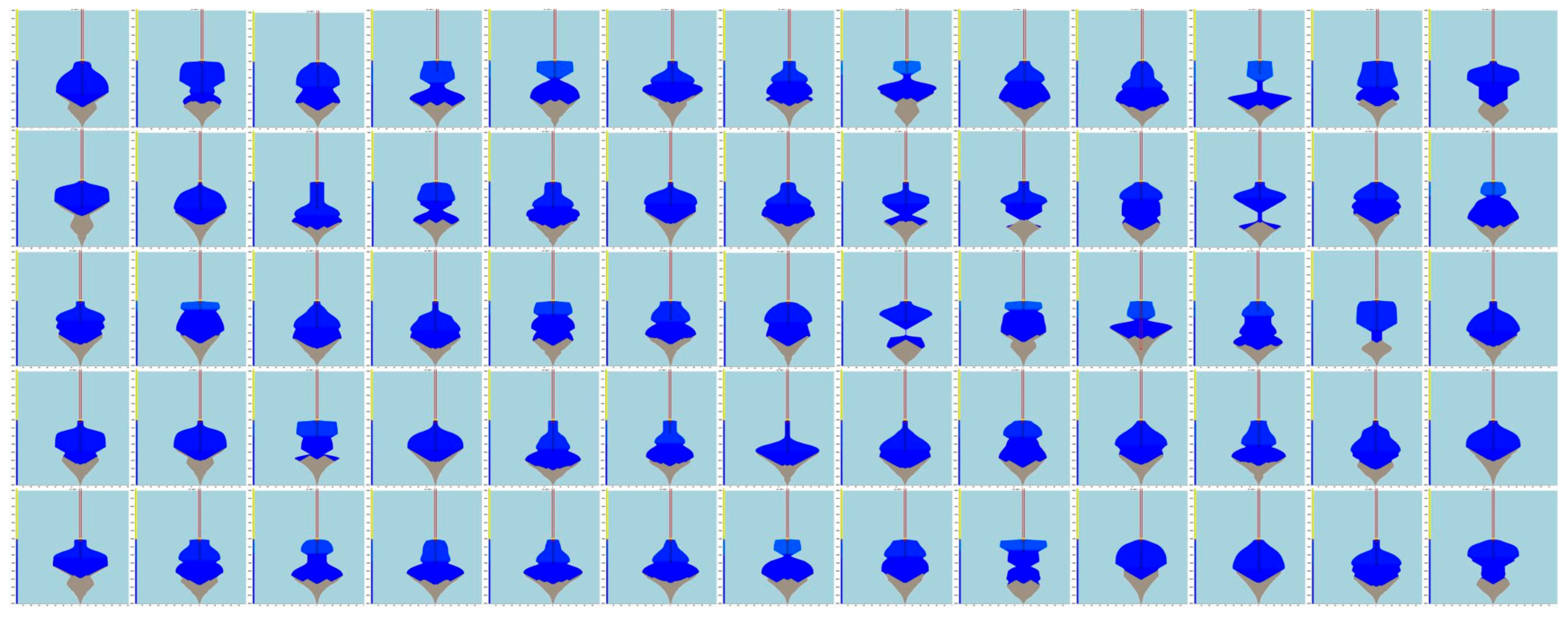
These random design parameters were imported into SSCLS software, and finally, 1258 groups of simulated caverns, their effective volumes, and their maximum radii were obtained after batch processing simulations. Some sections of the final cavern shape, simulated using the SSCLS software, are shown in Figure 4. As can be seen, there are significant differences in the cavern volumes and maximum radii corresponding to different process parameters, which are directly related to the expected revenue of the storage and the resource utilization of rock salt. These 1258 groups of 5-stage process parameters and the corresponding simulation results constitute our datasets.
In the evaluation of cavern construction results, the expected revenue and resource utilization values are the core concerns of cavern construction design. It is the goal of cavern design to build storage caverns with the largest possible capacity and the largest possible expected revenue using limited rock salt resources. The expected revenue of rock salt storage locations is determined by the storage capacity and is directly related to the cavern volume. For liquids, such as petroleum, the storage volume is the effective capacity of the storage. Here is an example representing storing natural gas. The working gas volume is the amount of natural gas stored in rock salt caverns during an injection and discharge cycle, which can generally be calculated using the following formula [33]:
V g = M m o l V S ρ g R P max Z max T max P min Z min T min
where Vg is the working gas volume of natural gas; Mmol is the molar mass of natural gas; Vs. is the effective capacity of the storage; ρ is the density of natural gas; R is the universal gas constant; Pmax and Pmin are the maximum and minimum pressures inside the salt cavern, respectively; Zmax and Zmin are the compression coefficients at the maximum and minimum internal pressures, respectively; Tmax and Tmin are the maximum temperature at injection and the minimum temperature at discharge, respectively. In the preliminary estimation, assuming ideal natural gas and constant injection and discharge temperature, the effective volume of 1 m3 of the salt cavern could store 119.9 m3 of natural gas. The current unit price of natural gas storage in China is 0.848 ¥/m3, and the expected revenue is the average of the cavern volume multiplied by the unit price of natural gas [34].
To ensure the safety and stability of the reservoir, a certain safety distance should be maintained between adjacent salt caverns (see Figure 2), which in turn affects the resource utilization of rock salt. The capacity coefficient (fc) of salt caverns (the ratio of the storage capacity of salt caverns to the space occupied) is calculated using the following formula, which can measure rock salt resource utilization [13].
f ¯ c = V ¯ j 2 r max + W 2 H c
where V ¯ j is the average cavern volume; W is the safe distance between adjacent caverns, usually 2 times the maximum cavern diameter (or 4rmax) in China [6,13,35,36]; and Hc is the cavern height.
Based on the dataset, the expected revenue and resource utilization of salt caverns can be derived. The evaluation indexes corresponding to some of the cavern construction process parameters are shown in Table 2.

3. Analysis and Discussion of the Main Design Parameters

The actual engineering data and cavern design experience recommend that main design parameters, including the distance between the inner tube and oil pad, the lifting height of the inner tube and oil pad, and the ratio of the lifting height of the inner tube and oil pad to the duration, have an influence on the construction results. Their influence laws can provide guidance for cavern design and optimization.
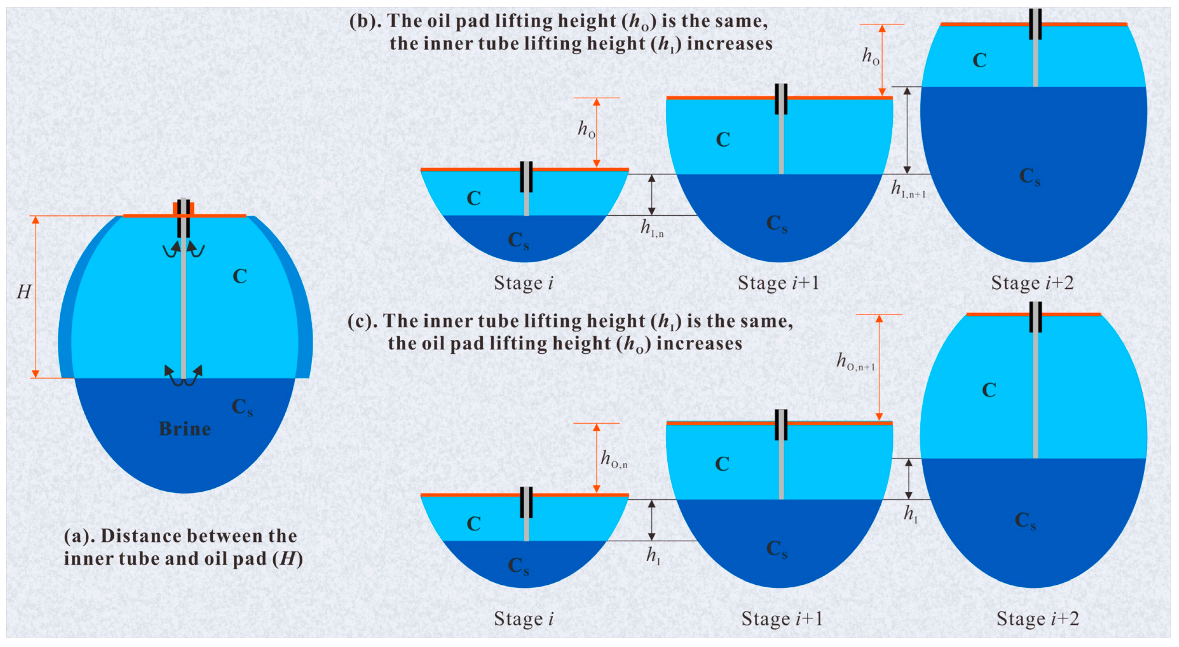
During the actual water solution mining process, as an example, fresh water is injected from the inner tube in the direct leaching mode, as shown in Figure 5a. The density of fresh water is lower than the density of high-concentration brine in the cavern; therefore, the injected fresh water will float up under the effect of the density difference. The brine below the inner tube height will not be replenished with fresh water; it will inevitably reach the saturation concentration, and the rock salt will no longer dissolve. Therefore, the inner tube height determines the lower limit of the rock salt dissolution height (see Figure 5b,c). The oil pad, which is solvent-resistant, determines the contact interface between the rock salt and brine, as well as the upper limit of the rock salt dissolution height.
The lifting height of the inner tube and oil pad, and the duration of the stage should meet a certain ratio to ensure that the rock salt within the height of the circulation zone is fully dissolved and the cavern is evenly expanded to obtain a regular shape. Therefore, the distance between the inner tube and the oil pad, their lifting heights, and their lifting rates were considered the main design parameters in this paper. The meanings of these process parameters are shown in Figure 5. The distance between the inner tube and the oil pad (H) is the oil pad height minus the inner tube height, which is the circulation zone height. The lifting height of the inner tube (hI) (lifting height of the oil pad (hO)) is the height of the next stage minus the height of the current stage. Further, the ratio of the oil pad lifting height (hO) to the stage duration (ti) in each stage can be obtained.

3.1. Distance between the Inner Tube and the Oil Pad

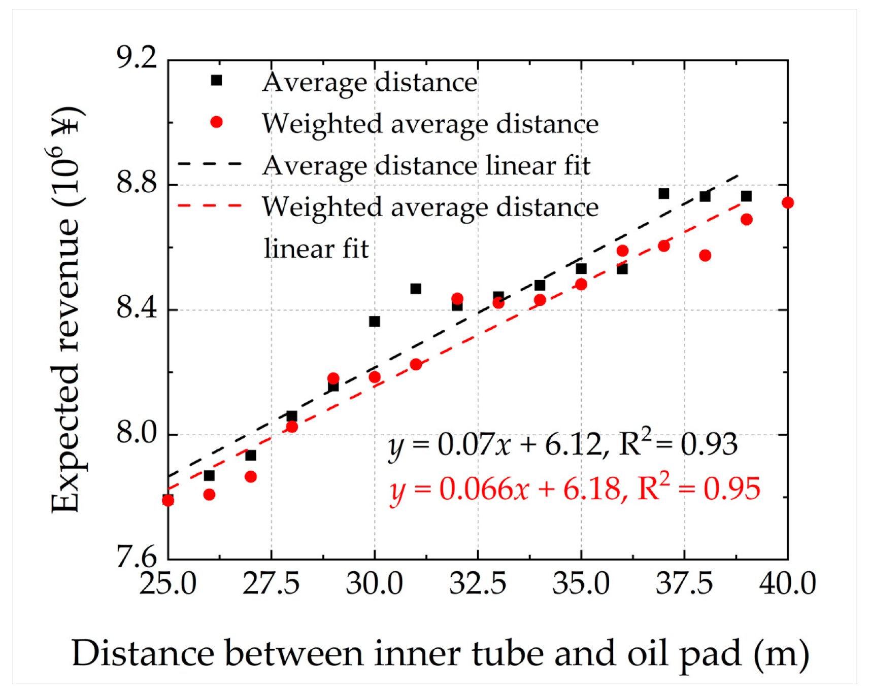
Here, the average distance between the inner tube and the oil pad for each stage (HA), from the dataset in Section 2, and the weighted average distance (HW) for each day were calculated and rounded down according to the following equation:
H ¯ A = R o u n d d o w n i = 1 5 H i 5 , 0
H ¯ W = R o u n d d o w n i = 1 5 H i × t i 120 × 5 ,   0
where H ¯ A and H ¯ W represent the average distance and the weighted average distance, respectively; Hi is the distance between the inner tube and the oil pad at stage i; and ti is the duration at stage i.
The average distance between the inner tube and the oil pad (HA), and the weighted average distance (HW) ranged between 25 and 40. Each number j in the range corresponds to the n group’s cavern data. The average cavern volume was obtained according to the following equation:
V ¯ j = k = 1 n V k n
where V ¯ j is the average cavern volume when the process parameter is equal to j and V k is the volume of the kth group of the dataset.
According to the previously mentioned formula, the variation law of the expected revenue and resource utilization of rock salt storage caverns with the distance between the inner tube and oil pad can be obtained, as shown in Figure 6 and Figure 7, respectively. It can be seen that the expected revenue and resource utilization of the storage caverns both increased gradually with an increase in the distance between the inner tube and the oil pad. Under the premise of a certain flow rate, the larger the distance between the inner tube and the oil pad, the larger the contact area between the rock salt and the brine (Figure 5a). On one hand, it leads to the greater dissolution of rock salt, which results in a larger storage volume and higher expected revenue. On the other hand, the more uniformly the injected fresh water mixes with the brine in the cavern, the more regular the shape of the salt cavern and the smaller the maximum radius. The increase in the distance between the inner tube and the oil pad leads to higher expected revenue and resource utilization. It can be suggested that a large distance between the inner tube and the oil pad (greater than 30 m) should be designed for more storage and larger resource utilization.

3.2. Lifting Height of the Inner Tube and the Oil Pad

The average lifting height of the inner tube and the oil pad is calculated and rounded down according to the following equation:
h ¯ = R o u n d d o w n i = 1 4 h i + 1 h i 4 ,   0
where h ¯ is the average lifting height, hi+1 is the lifting height of stage i + 1, and hi is the lifting height of stage i.
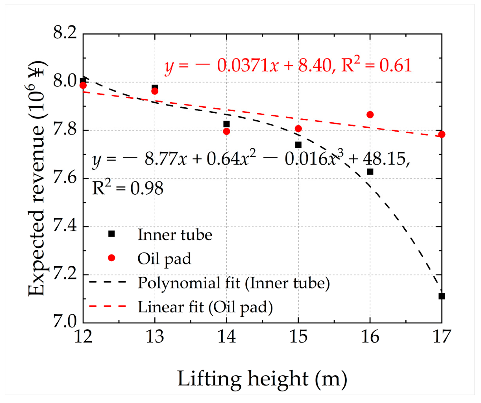
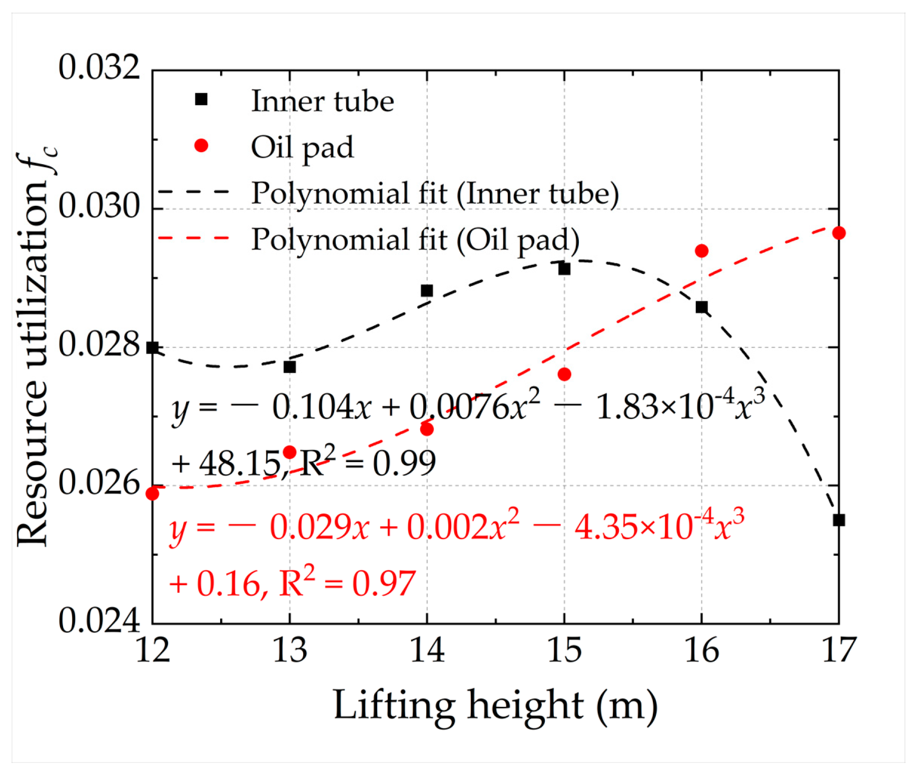
Each number j in the average lifting height range corresponded to n caverns, and the cavern volume was averaged according to Equation (7). The variation in the expected revenue and resource utilization of the rock salt storage caverns, based on the lifting height of the inner tube and the oil pad, were further obtained, as shown in Figure 8 and Figure 9, respectively. It can be seen that the expected revenue of the storage caverns gradually decreased with an increase in the inner tube lifting height, and the resource utilization did not change significantly. As the oil pad lifting height increased, the expected revenue decreased slightly, while resource utilization increased significantly. This suggests that reducing the inner tube lifting height was beneficial for improving the expected revenue, and increasing the oil pad lifting height was beneficial for improving rock salt resource utilization. Under the premise of the same oil pad lifting height (Figure 5b), the larger the inner tube lifting height, the larger the area below the inner tube that could not be dissolved because of the saturated brine, and the smaller the dissolvable area above the inner tube. This led to a significant reduction in the cavern volume. Thus, the storage capacity and expected revenue of are salt caverns were decreased. However, the circulation zone height slightly decreased with the increase in the inner tube lifting height, and the degree of brine mixing remained basically unchanged. Thus, the change in salt cavern shape and maximum radius was small, which had a small impact on the resource utilization of the storage cavern. At the same inner tube lifting height (Figure 5c), the larger the oil pad lifting height and the slightly larger the insoluble area below the inner tube. Therefore, the cavern volume and expected revenue were slightly reduced. At the same time, the circulation zone height was significantly increased, the brine mixing was more uniform, the cavern shape was more regular, the maximum radius was reduced, and resource utilization was increased. Therefore, the reduction in the inner tube lifting height led to more expected revenue, and the increase in the oil pad lifting height led to higher resource utilization. In the actual project, it is recommended to reduce the inner tube lifting height (to less than 15 m) and increase the oil pad lifting height (to greater than 14 m), considering the field conditions and influential laws.

3.3. Ratio of the Lifting Height to Duration

The process of rock salt dissolution and cavern expansion takes a long time. Therefore, the ratio of the lifting height to the duration may have an influence on the cavern construction results. In this section, the variation in expected revenue and resource utilization of salt storage caverns, with the ratio of lifting height to the duration, are discussed. The average ratio of the lifting height to the duration can be calculated according to the following equation:
h ¯ = R o u n d d o w n i = 1 4 h i + 1 h i / t i 4 ,   0
where, h ¯ is the ratio of lifting height to duration, ti is the duration of each stage, hi+1 is the lifting height of stage i + 1, and hi is the lifting height of stage i.
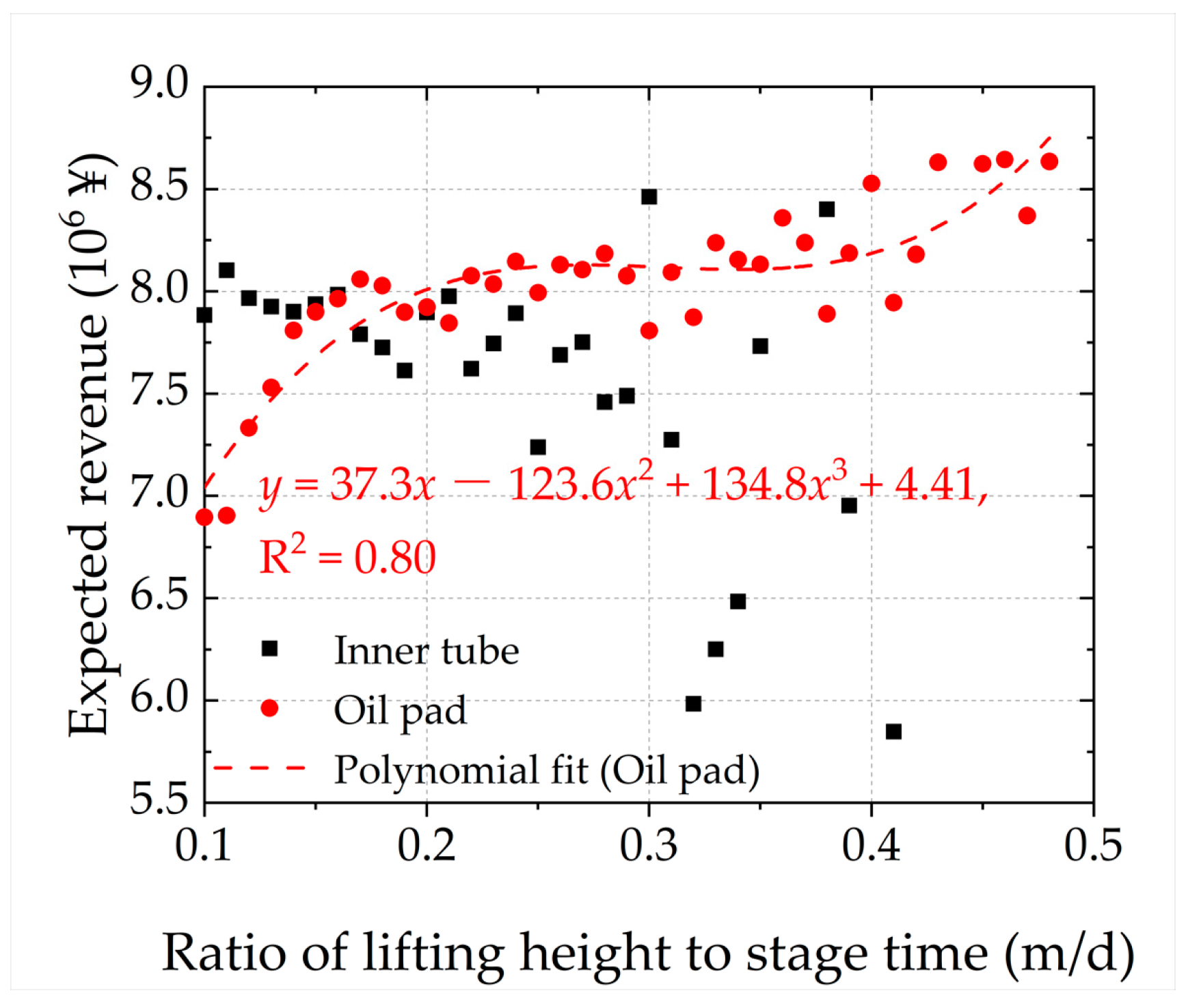
The variation in the expected revenue and resource utilization of salt storage caverns, based on the ratio of lifting height to duration, were further obtained and are shown in Figure 10 and Figure 11, respectively. As the ratio of the inner tube lifting height to duration increased, there was no clear pattern in the changes in expected revenue and resource utilization, which may be larger or smaller, haphazard, and described by the fluctuation. The reason for this is that the inner tube mouth may be submerged in the sediment at the bottom. The circulation zone height was the greater value of the inner tube height and the insoluble substance height. Therefore, there was no significant relationship between the expected revenue or resource utilization and the inner tube lifting rate. As the oil pad lifting rate increased, both the expected revenue and resource utilization gradually increased. The faster the oil pad was lifted, the faster the circulation zone height increased, the larger the contact area between the rock salt and water, the larger the salt cavern volume, and the greater the expected revenue. At the same time, the more uniformly the injected fresh water and brine 2343 mixed, the more regular the salt cavern shape was and the greater the capacity coefficient and the rock salt resource utilization were. Therefore, as the ratio of the oil pad lifting height to the duration increased, both the expected revenue and resource utilization gradually increased. In the actual project, it is recommended to increase the ratio of the oil pad lifting height (greater than 0.2 m/d) to the duration.
In summary, the design criteria for the construction of rock salt energy storage caverns, considering the economic benefits and resource utilization, are shown in Table 3.

4. Conclusions

In this paper, based on the randomly generated 1258 groups of multi-stage cavern construction process parameters for five direct leaching stages, the cavern construction results were obtained through batch processing using single-well salt cavern leaching simulation software (SSCLS). According to these data, the influences of the key process parameters on the expected revenue and resource utilization were discussed. The following conclusions were obtained:
(1) During the cavern design and construction process, the distance between the inner tube and the oil pad should be greater than 30 m. Increasing the distance is beneficial for improving the expected revenue and utilization of rock salt resources. As the distance increases, the contact area between rock salt and brine becomes larger, and the injected freshwater mixes more evenly with the brine. This leads to a larger and more regular shape of salt caverns, which will increase both the expected revenue and the capacity coefficient.
(2) The inner tube lifting height should be less than 15 m, and the oil pad lifting height should be greater than 14 m. Reducing the inner tube lifting height is beneficial for improving the expected revenue of salt caverns, and increasing the oil pad lifting height is beneficial for improving the rock salt resource utilization rate.
(3) The ratio of the oil pad lifting height to the duration should be greater than 0.2 m/d. In practical engineering, increasing the ratio of the oil pad lifting height to the duration is beneficial for improving the expected revenue and the rock salt resource utilization rate.
The key process parameter design principles proposed in this paper will greatly enhance the efficiency of rock salt cavern construction design and shape control and can provide guidance for the more reasonable and adequate utilization of rock salt resources in actual projects. It is still important to note that the design criteria in this paper are only applicable to the direct leaching process for vertical caverns. In the next study, the diverse leaching process needs to be discussed further. More importantly, this paper does not consider the effect of insoluble interlayers and insoluble substance content variation on the construction results. Insoluble sediments are very detrimental to cavern construction and oil and gas storage processes. On the one hand, insoluble sediments may clog the tube during the leaching process and oil and gas extraction processes. On the other hand, these insoluble sediments will reduce the effective capacity and expected revenue of the cavern. The adoption of porous media percolation and multiphase flow theory [37,38,39] to study the influence of insoluble sediments on the leaching process and oil and gas extraction processes may become a hot spot for future research.

Author Contributions

Conceptualization, H.S. and J.L.; software, J.L. and H.S.; validation, S.Z. and J.L.; formal analysis, Z.W. and H.S.; investigation, Z.W. and Q.L.; data curation, Z.W. and S.Z.; writing-original draft preparation, H.S., S.Z. and Z.N.; writing-review and editing, J.L. and Z.N.; visualization, J.L. and S.Z.; supervision, J.L. and H.S.; funding acquisition, J.L. All authors have read and agreed to the published version of the manuscript.

Funding

This research was funded by the National Natural Science Foundation of China, grant numbers 52109138 and 52122403; the Basic Science Center Program for Multiphase Evolution in Hyper-gravity of the National Natural Science Foundation of China, grant number 51988101; and the Fundamental Research Funds for the Central Universities, grant number 2021QNA4026.

Institutional Review Board Statement

Not applicable.

Informed Consent Statement

Not applicable.

Data Availability Statement

Not applicable.

Conflicts of Interest

The authors declare no conflict of interest.

Nomenclature

mMeter
m3Cubic meter
¥Chinese ¥
VgWorking gas volume, m3
MmolMolar mass of natural gas, g/mol
VsEffective capacity of the storage, m3
VcVolume of circulation zone, m3
VdVolume of the dead zone under inner tube, m3
CBrine concentration in the circulation, g/L
rRadius in the column coordinate system
ΘAngle in the column coordinate system
zHeight in the column coordinate system
tTime, s
CsSaturated concentration, g/L
DScattering coefficient
QFlow of injected water, m3/h
UInsoluble content of the micro-element on point
uContent of insoluble in the salt
ρsDensity of rock salt, kg/m3
ρDensity of natural gas, kg/m3
RUniversal gas constant, 8.314 J/(mol·K)
PmaxMaximum pressures inside salt caverns, kPa
PminMinimum pressures inside salt caverns, kPa
ZmaxCompression coefficients at the maximum internal pressures
ZminCompression coefficients at the minimum internal pressures
TmaxMaximum temperature at injection, K
TminMinimum temperature at discharge, K
fcCapacity coefficient
f ¯ c Average capacity coefficient
VkCavern volume kth of the n groups data, m3
V ¯ j Average volume when the process parameter is equal to j, m3
rmaxMaximum radius, m
WSafe distance between adjacent caverns, m
HcCavern height, m
HDistance between the inner tube and oil pad, m
hiLifting height of stage i, m
hoLifting height of oil pad, m
hILifting height of inner tube, m
tiDuration, day
H ¯ A Average distance between the inner tube and oil pad, m
H ¯ W Weighted average distance between the inner tube and oil pad, m
h ¯ Average lifting height, m
h ¯ Ratio of lifting height to duration, m/day
iStage i
nn groups data
kGroup k of the n groups data, summation index
jThe process parameters are rounded down to a value equal to j
rounddown (x, 0)Function of the round down toward zero, for example, rounddown (23.7, 0) = 23, rounddown (−23.2, 0) = −23

References

  1. Mortazavi, A.; Nasab, H. Analysis of the behavior of large underground oil storage caverns in salt rock. Int. J. Numer. Anal. Methods. Geomech. 2017, 41, 602–624. [Google Scholar] [CrossRef]
  2. Yang, C.; Wang, T.; Li, Y.; Yang, H.; Li, J.; Qu, D.; Xu, B.; Yang, Y.; Daemen, J.J.K. Feasibility analysis of using abandoned salt caverns for large-scale underground energy storage in China. Appl. Energy 2015, 137, 467–481. [Google Scholar] [CrossRef]
  3. Liu, W.; Zhang, Z.; Chen, J.; Fan, J.; Jiang, D.; Daemen, J.J.K.; Li, Y. Physical simulation of construction and control of two butted-well horizontal cavern energy storage using large molded rock salt specimens. Energy 2019, 185, 682–694. [Google Scholar] [CrossRef]
  4. Zhang, N.; Liu, W.; Zhang, Y.; Shan, P.; Shi, X. Microscopic pore structure of surrounding rock for underground strategic petroleum reserve (SPR) caverns in bedded rock salt. Energies 2020, 13, 1565. [Google Scholar] [CrossRef]
  5. Zhang, N.; Ma, J.; Wang, M.; Zhang, Q.; Li, J.; Fan, P. Comprehensive risk evaluation of underground energy storage caverns in bedded rock salt. J. Loss Prevent. Proc. 2016, 45, 264–276. [Google Scholar] [CrossRef]
  6. Li, J.; Wang, Z.; Zhang, S.; Shi, X.; Xu, W.; Zhuang, D.; Liu, J.; Li, Q.; Chen, Y. Machine-learning-based capacity prediction and construction parameter optimization for energy storage salt caverns. Energy 2022, 254, 124238. [Google Scholar] [CrossRef]
  7. Ling, D.; Zhu, S.; Zheng, J.; Xu, Z.; Zhao, Y.; Chen, L.; Shi, X.; Li, J. A simulation method for the dissolution construction of salt cavern energy storage with the interface angle considered. Energy 2023, 263, 125792. [Google Scholar] [CrossRef]
  8. Li, J.; Shi, X.; Yang, C.; Li, Y.; Wang, T.; Ma, H. Mathematical model of salt cavern leaching for gas storage in high-insoluble salt formations. Sci. Rep. 2018, 8, 372. [Google Scholar] [CrossRef]
  9. Yang, J.; Li, H.; Yang, C.; Li, Y.; Wang, T.; Shi, X.; Han, Y. Physical simulation of flow field and construction process of horizontal salt cavern for natural gas storage. J. Nat. Gas. Sci. Eng. 2020, 82, 103527. [Google Scholar] [CrossRef]
  10. Li, L.; Rivas, E.; Gracie, R.; Dusseault, M.B. Methodology for the nonlinear coupled multi-physics simulation of mineral dissolution. Int. J. Numer. Anal. Methods Geomech. 2021, 45, 2193–2213. [Google Scholar] [CrossRef]
  11. Yang, C.; Wang, T.; Qu, D.; Ma, H.; Li, Y.; Shi, X.; Daemen, J.J.K. Feasibility analysis of using horizontal caverns for underground gas storage: A case study of Yunying salt district. J. Nat. Gas. Sci. Eng. 2016, 36, 252–266. [Google Scholar] [CrossRef]
  12. Wang, T.; Yang, C.; Li, J.; Li, J.; Shi, X.; Ma, H. Failure analysis of overhanging blocks in the walls of a gas storage salt cavern: A case study. Rock. Mech. Rock. Eng. 2017, 50, 125–137. [Google Scholar] [CrossRef]
  13. Li, J.; Shi, X.; Zhang, S. Construction modeling and parameter optimization of multi-step horizontal energy storage salt caverns. Energy 2020, 203, 117840. [Google Scholar] [CrossRef]
  14. Durie, R.W.; Jessen, F.W. The influence of surface features in the salt dissolution process. SPE J. 1964, 4, 275–281. [Google Scholar] [CrossRef]
  15. Durie, R.W.; Jessen, F.W. Mechanism of the dissolution of salt in the formation of underground salt cavities. SPE J. 1964, 4, 183–190. [Google Scholar] [CrossRef]
  16. Kazemi, H.; Jessen, F.W. Mechanism of flow and controlled dissolution of salt in solution mining. Soc. Pet. Eng. J. 1964, 4, 317–328. [Google Scholar]
  17. Reda, D.C.; Russo, A.J. Experimental studies of salt-cavity leaching by freshwater injection. SPE Prod. Eng. 1986, 1, 82–86. [Google Scholar] [CrossRef]
  18. Li, L.; Gracie, R.; Dusseault, M.B.; Xiao, N.; Liang, W. Modeling and verification of non-linear mineral dissolution processes with buoyancy effects. Int. J. Rock. Mech. Min. 2023, 161, 105257. [Google Scholar] [CrossRef]
  19. Xiao, N.; Liang, W.; Yu, Y.; Zhang, S.; Li, L. Shape prediction and parameter optimization of single-well retreating horizontal salt cavern for energy storage. J. Energy Storage 2023, 59, 106557. [Google Scholar] [CrossRef]
  20. Saberian, A. Numerical Simulation of Development of Solution-Mined Storage Cavities. Ph.D. Thesis, University of Texas System, Austin, TX, USA, 1974. [Google Scholar]
  21. Kunstman, A.; Urbanczyk, K. Application of WinUbro software to modelling of carven development in trona deposit. In Proceedings of the Solution Mining Research Institute Technical Conference, Krakow, Poland, 27–28 April 2009. [Google Scholar]
  22. Wan, J.; Peng, T.; Shen, R.; Jurado, M. Numerical model and program development of TWH salt cavern construction for UGS. J. Pet. Sci. Eng. 2019, 179, 930–940. [Google Scholar] [CrossRef]
  23. Wang, Y.; Zhou, D.; Deng, L.; Fu, Y.; Guan, D. Study on improving the solution-mining processes of salt-cavern gas storage and field applications of the improved process technology. J. Southwest Pet. Univ. 2018, 5, 1674–5086. [Google Scholar] [CrossRef]
  24. Wang, J.; Zhu, K.; Li, Y.; Fan, L.; Wang, W.; Ge, C. Optimization of key cavity construction parameters of Jintan salt-cavern gas storage. Oil Drill. Prod. Technol. 2020, 4, 471–475. [Google Scholar] [CrossRef]
  25. Ren, S.; Tang, K.; Yi, L.; Chen, J.; Liu, W. Research on two-well solution mining cavity expansion with small well space. Chin. J. Undergr. Space Eng. 2017, 14, 805–812. [Google Scholar]
  26. Wan, J.; Peng, T.; Jurado, M.J.; Shen, R.; Yuan, G.; Ban, F. The influence of the water injection method on two-well-horizontal salt cavern construction. J. Pet. Sci. Eng. 2020, 184, 106560. [Google Scholar] [CrossRef]
  27. Wan, J.; Peng, T.; Yuan, G.; Ban, F.; Jurado, M.J.; Xia, Y. Influence of tubing/oil-blanket lifting on construction and geometries of two-well-horizontal salt caverns. Tunn. Undergr. Space Technol. 2021, 108, 103688. [Google Scholar] [CrossRef]
  28. Li, J.; Shi, X.; Yang, C.; Li, Y.; Wang, T.; Ma, H.; Shi, H.; Li, J.; Liu, J. Repair of irregularly shaped salt cavern gas storage by re-leaching under gas blanket. J. Nat. Gas. Sci. Eng. 2017, 45, 848–859. [Google Scholar] [CrossRef]
  29. Li, J.; Yang, C.; Shi, X.; Xu, W.; Li, Y.; Daemen, J.J.K. Construction modeling and shape prediction of horizontal salt caverns for gas/oil storage in bedded salt. J. Pet. Sci. Eng. 2020, 190, 107058. [Google Scholar] [CrossRef]
  30. Yang, C.; Wang, T. Advance in deep underground energy storage. Chin. J. Rock Mech. Eng. 2022, 41, 1729–1759. [Google Scholar] [CrossRef]
  31. Li, J.; Tang, Y.; Shi, X.; Xu, W.; Yang, C. Modeling the construction of energy storage salt caverns in bedded salt. Appl. Energy 2019, 255, 113866. [Google Scholar] [CrossRef]
  32. Yang, C.; Wang, T.; Chen, X. Theoretical and technological challenges of deep underground energy storage in China. Engineering 2022. [Google Scholar] [CrossRef]
  33. Ślizowski, J.; Lankof, L.; Urbańczyk, K.; Serbin, K. Potential capacity of gas storage caverns in rock salt bedded deposits in Poland. J. Nat. Gas. Sci. Eng. 2017, 43, 167–178. [Google Scholar] [CrossRef]
  34. Li, Q.; Ning, Z.; Liu, J.; Xu, W.; Zhan, L.; Liu, J.; Chen, Y.; Shi, X.; Chen, X.; Li, J. Stability and economic evaluation of multi-step horizontal salt caverns with different step distances in bedded salt formations. J. Energy Storage 2023, 57, 106192. [Google Scholar] [CrossRef]
  35. Liu, W.; Zhang, Z.; Chen, J.; Jiang, D.; Wu, F.; Fan, J.; Li, Y. Feasibility evaluation of large-scale underground hydrogen storage in bedded salt rocks of China: A case study in Jiangsu province. Energy 2020, 198, 117348. [Google Scholar] [CrossRef]
  36. Zhang, N.; Shi, X.; Zhang, Y.; Shan, P. Tightness analysis of underground natural gas and oil storage caverns with limit pillar widths in bedded rock salt. IEEE Access 2020, 8, 12130–12145. [Google Scholar] [CrossRef]
  37. Yan, G.; Li, Z.; Bore, T.; Galindo Torres, S.A.; Scheuermann, A.; Li, L. A lattice boltzmann exploration of two-phase displacement in 2D porous media under various pressure boundary conditions. J. Rock. Mech. Geotech. 2022, 14, 1782–1798. [Google Scholar] [CrossRef]
  38. Yan, G.; Ma, Y.; Scheuermann, A.; Li, L. The hydraulic properties of aquabeads considering forchheimer flow and local heterogeneity. Geotech. Test. J. 2022, 45, 20210234. [Google Scholar] [CrossRef]
  39. Yan, G.; Li, Z.; Galindo Torres, S.A.; Scheuermann, A.; Li, L. Transient two-phase flow in porous media: A literature review and engineering application in geotechnics. Geotechnics 2022, 2, 32–90. [Google Scholar] [CrossRef]
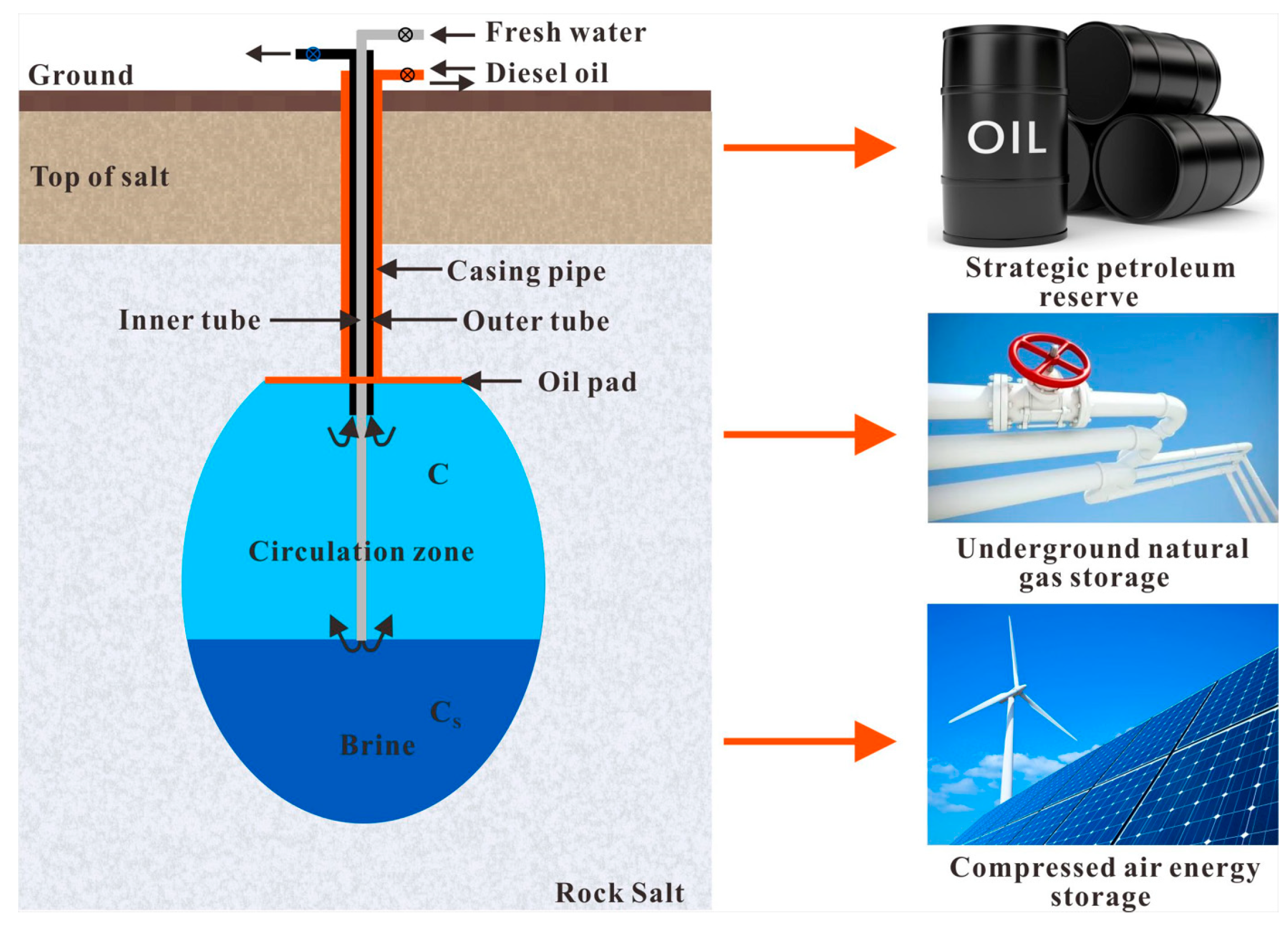
Figure 1. Schematic diagram of the water solution mining process.
Sustainability 15 06870 g001
Figure 2. Irregular cavern shapes result in small storage capacity, a low salt resource utilization ratio, and poor safety. (a,b) These two rock cavern shapes occupy the same underground space and consume the same rock salt resources. However, the storage capacity of (a) is significantly larger than that of (b).
Sustainability 15 06870 g002
Figure 3. Diagram of the cavern construction process.
Sustainability 15 06870 g003
Figure 4. A portion (65) of the 1258 caverns, simulated using SSCLS software. The dark blue color represents the salt cavern filled with brine, and the light blue color in the background represents rock salt.
Sustainability 15 06870 g004
Figure 5. Schematic diagram of key process parameters for cavern construction design. The distance between the inner tube and the oil pad (H) is the oil pad height minus the inner tube height, which is the circulation zone height. The lifting height of the inner tube (hI) (lifting height of the oil pad (hO)) is the height of the next stage minus the height of the current stage. Further, the ratio of the oil pad lifting height (hO) to the stage duration (ti) in each stage can be obtained.
Sustainability 15 06870 g005
Figure 6. Variation in the expected revenue based on the distance between the inner tube and the oil pad.
Sustainability 15 06870 g006
Figure 7. Variation in resource utilization based on the distance between the inner tube and the oil pad.
Sustainability 15 06870 g007
Figure 8. Variation in expected revenue with the average lifting height.
Sustainability 15 06870 g008
Figure 9. Variation in resource utilization with the average lifting height.
Sustainability 15 06870 g009
Figure 10. Variation in the expected revenue with the ratio of the lifting height to the duration.
Sustainability 15 06870 g010
Figure 11. Variation in resource utilization with the ratio of the lifting height to the duration.
Sustainability 15 06870 g011
Table 1. The partial key parameters randomly generated for the cavern construction process.
StageProcess ParametersG-1G-2G-3G-4G-5G-6G-7G-8
1Inner tube depth (m)00000000
Oil pad depth (m)2026231114232624
Duration (days)5526472722604740
2Inner tube depth (m)815105520155
Oil pad depth (m)2326232221354343
Duration (days)17812482112190148184155
3Inner tube depth (m)1018161215191923
Oil pad depth (m)2631302446625865
Duration (days)175245263217754975110
4Inner tube depth (m)2628252431224538
Oil pad depth (m)6743717475726275
Duration (days)8910587132133185160159
5Inner tube depth (m)4342596769425558
Oil pad depth (m)8080808080808080
Duration (days)103100121112180158134136
Notice: G-n represents the nth group, only 8 groups of data are listed here.
Table 2. Expected revenue and resource utilization of salt caverns.
IndicatorsG-1G-2G-3G-4G-5G-6G-7G-8
Cavern volume (103 m3)38.5743.1943.3343.8048.0684.1984.1984.20
Maximum radius (m)27.230.730.729.230.635.030.729.4
Expected revenue (106 ¥)3.924.394.414.454.898.568.568.56
Resource utilization fc0.0180.0160.0160.0180.0180.0240.0310.034
Table 3. The design criteria for the construction of rock salt energy storage.
ParametersDistance between Inner Tube and Oil PadInner Tube Lifting HeightOil Pad Lifting HeightRatio of Lifting Height to Duration
Criteria>30 m<15 m>14 m>0.2 m/d
Disclaimer/Publisher’s Note: The statements, opinions and data contained in all publications are solely those of the individual author(s) and contributor(s) and not of MDPI and/or the editor(s). MDPI and/or the editor(s) disclaim responsibility for any injury to people or property resulting from any ideas, methods, instructions or products referred to in the content.