
Shear Thickening Fluids in Cork Agglomerates: An Exploration of Advantages and Drawbacks
 , ,
, ,  and
and 
Abstract
1. Introduction
2. Materials and Methods
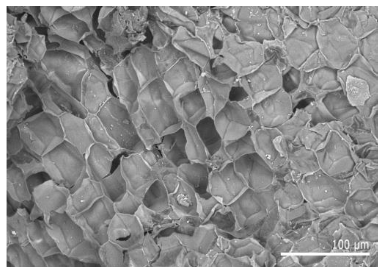
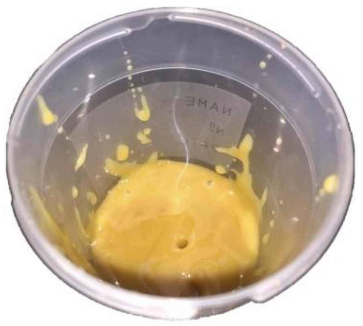
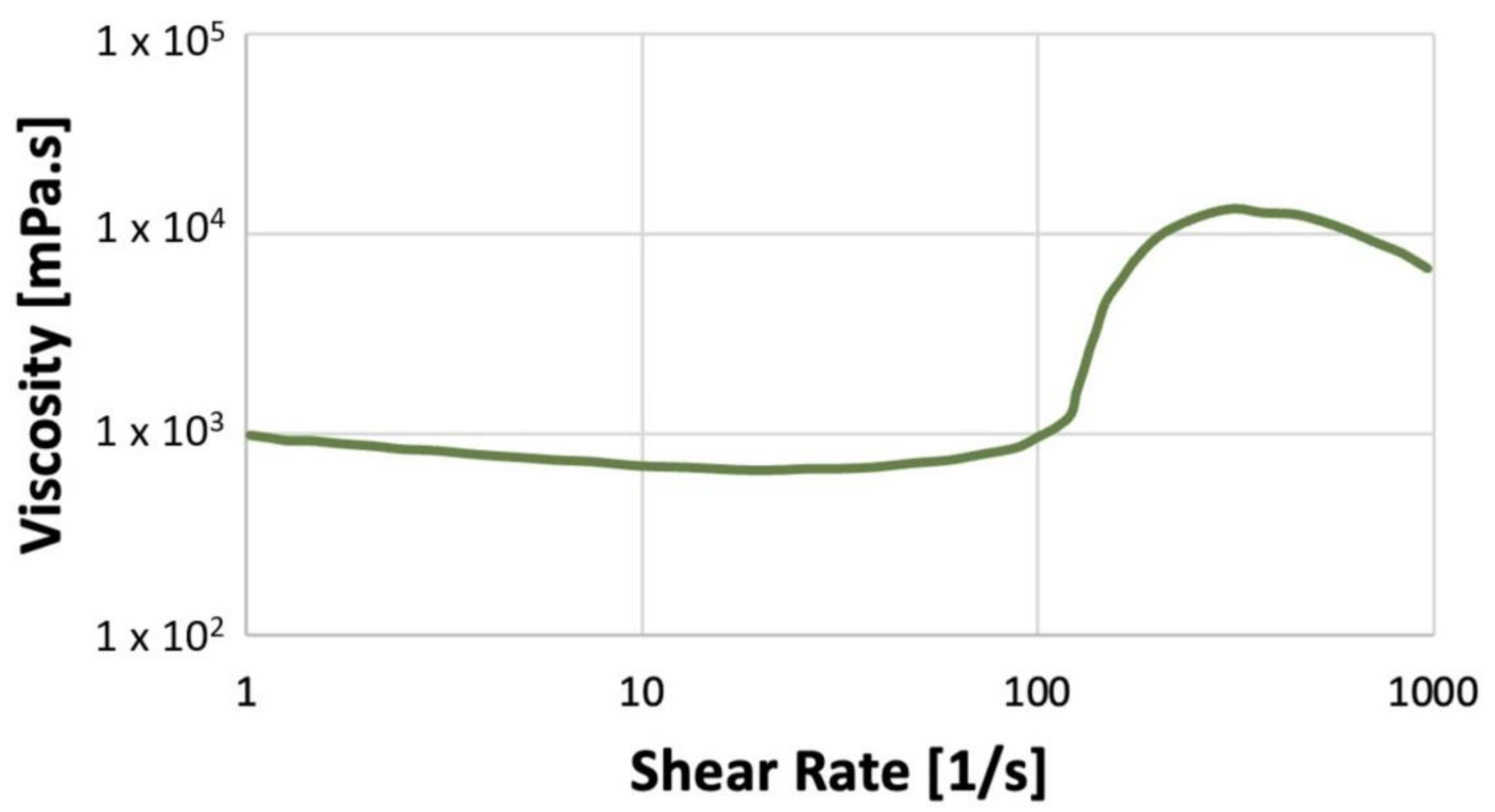
2.1. Materials
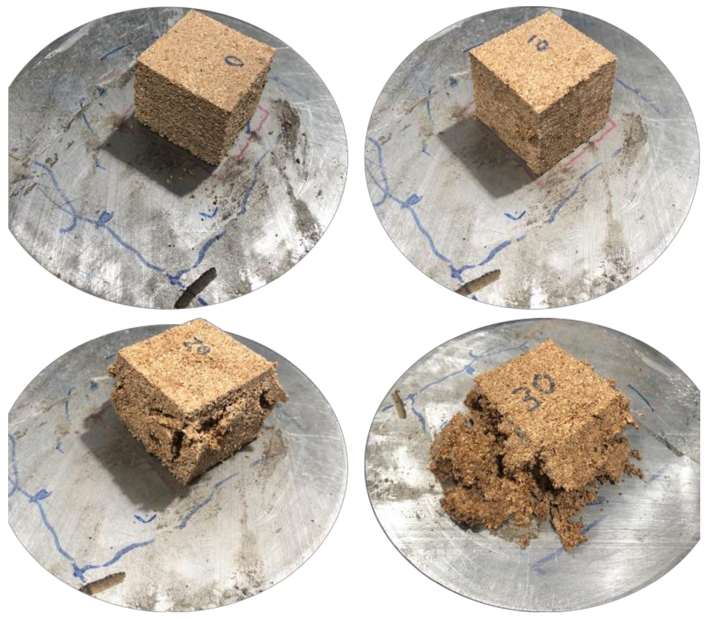
2.2. Samples Production
3. Experimental Testing
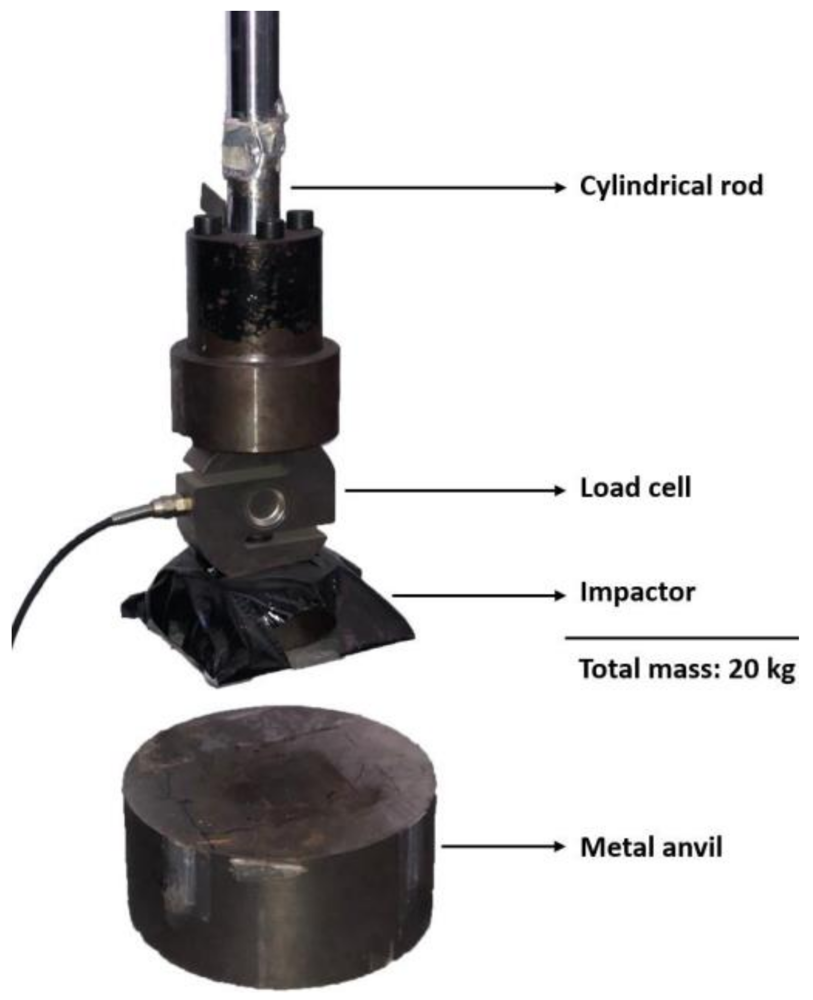
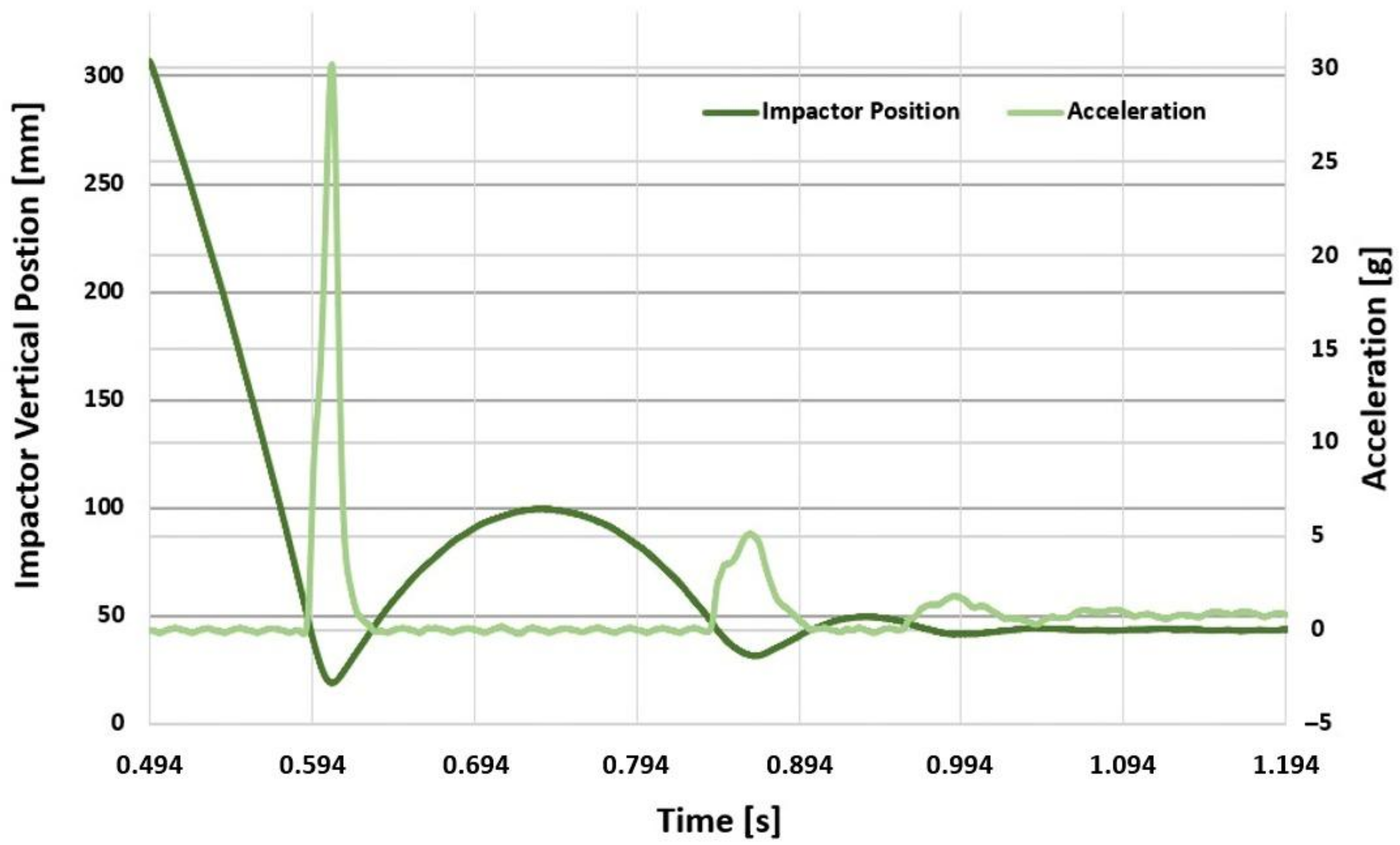
3.1. Dynamic Impact Tests
3.2. Quasi-Static Tests
4. Results and Discussion
4.1. Impact Tests
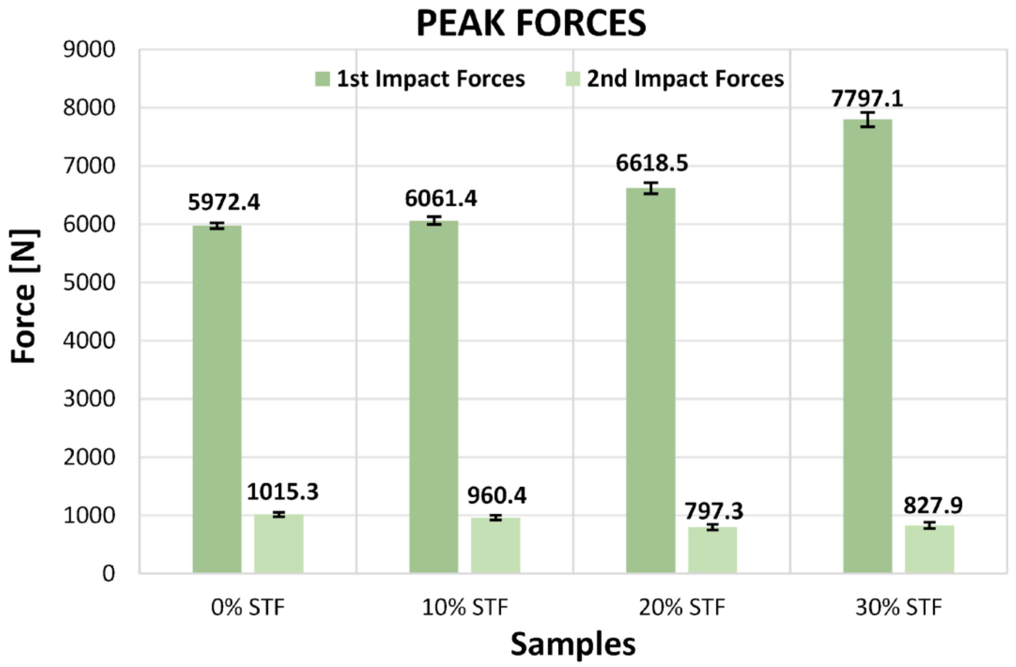
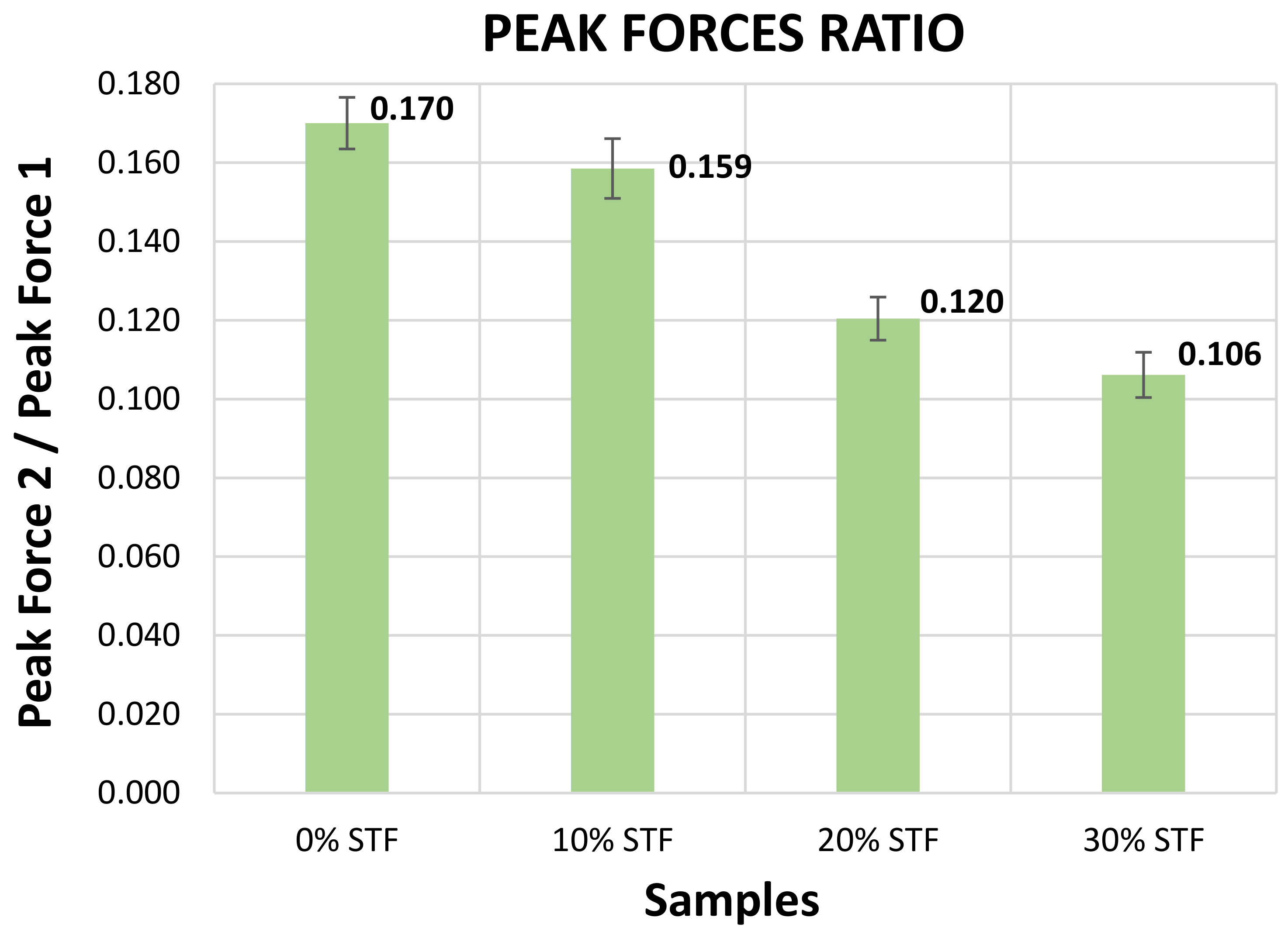
4.1.1. Peak Forces
4.1.2. Peak Acceleration
4.1.3. Absorbed Energy Densities
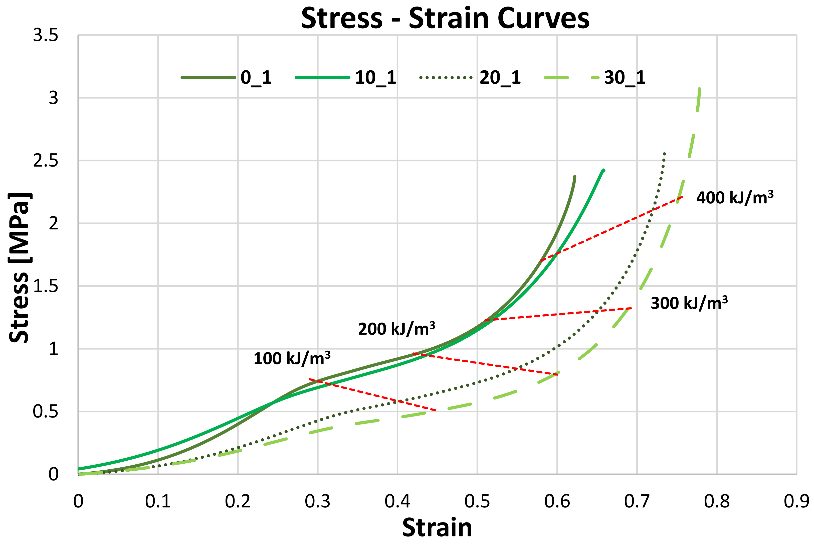
4.2. Quasi-Static Tests
Energy Densities
5. Conclusions
Supplementary Materials
Author Contributions
Funding
Data Availability Statement
Conflicts of Interest
References
- Gürgen, S.; de Sousa, R.J.A. Rheological and deformation behavior of natural smart suspensions exhibiting shear thickening properties. Arch. Civ. Mech. Eng. 2020, 20, 110. [Google Scholar] [CrossRef]
- Lee, Y.S.; Wagner, N.J. Dynamic properties of shear thickening colloidal suspensions. Rheol. Acta 2003, 42, 199–208. [Google Scholar] [CrossRef]
- Barnes, H.A. Shear-Thickening (“Dilatancy”) in Suspensions of Nonaggregating Solid Particles Dispersed in Newtonian Liquids. J. Rheol. 1989, 33, 329–366. [Google Scholar] [CrossRef]
- Fischer, C.; Braun, S.A.; Bourban, P.E.; Michaud, V.; Plummer, C.J.; Månson, J.A. Dynamic properties of sandwich structures with integrated shear-thickening fluids. Smart Mater. Struct. 2006, 15, 1467–1475. [Google Scholar] [CrossRef]
- Pinto, F.; Meo, M. Design and Manufacturing of a Novel Shear Thickening Fluid Composite (STFC) with Enhanced out-of-Plane Properties and Damage Suppression. Appl. Compos. Mater. 2017, 24, 643–660. [Google Scholar] [CrossRef]
- FGalindo-Rosales, J.; Martínez-Aranda, S.; Campo-Deanõ, L. CorkSTFμfluidics—A novel concept for the development of eco-friendly light-weight energy absorbing composites. Mater. Des. 2015, 82, 326–334. [Google Scholar] [CrossRef]
- Wagner, N.J.; Brady, J.F. Shear thickening in colloidal dispersions. Phys. Today 2009, 62, 27–32. [Google Scholar] [CrossRef]
- Gürgen, S.; Kuşhan, M.C.; Li, W. Shear thickening fluids in protective applications: A review. Prog. Polym. Sci. 2017, 75, 48–72. [Google Scholar] [CrossRef]
- Lee, Y.S.; Wetzel, E.D.; Wagner, N.J. The ballistic impact characteristics of Kevlar® woven fabrics impregnated with a colloidal shear thickening fluid. J. Mater. Sci. 2003, 38, 2825–2833. [Google Scholar] [CrossRef]
- Majumdar, A.; Butola, B.S.; Srivastava, A. An analysis of deformation and energy absorption modes of shear thickening fluid treated kevlar fabrics as soft body armour materials. Mater. Des. 2013, 51, 148–153. [Google Scholar] [CrossRef]
- Haro, E.E.; Odeshi, A.G.; Szpunar, J.A. The energy absorption behavior of hybrid composite laminates containing nano-fillers under ballistic impact. Int. J. Impact Eng. 2016, 96, 11–22. [Google Scholar] [CrossRef]
- Na, W.; Ahn, H.; Han, S.; Harrison, P.; Park, J.K.; Jeong, E.; Yu, W.R. Shear behavior of a shear thickening fluid-impregnated aramid fabrics at high shear rate. Compos. Part B Eng. 2016, 97, 162–175. [Google Scholar] [CrossRef]
- Kaczynski, P.; Ptak, M.; Wilhelm, J.; Fernandes, F.A.O.; de Sousa, R.J.A. High-energy impact testing of agglomerated cork at extremely low and high temperatures. Int. J. Impact Eng. 2019, 126, 109–116. [Google Scholar] [CrossRef]
- Fernandes, F.A.O.; Jardin, R.T.; Pereira, A.B.; de Sousa, R.J.A. Comparing the mechanical performance of synthetic and natural cellular materials. Mater. Des. 2015, 82, 335–341. [Google Scholar] [CrossRef]
- Santos, P.T.; Pinto, S.; Marques, P.A.A.P.; Pereira, A.B.; de Sousa, R.J.A. Agglomerated cork: A way to tailor its mechanical properties. Compos. Struct. 2017, 178, 277–287. [Google Scholar] [CrossRef]
- Garcia, A.R.; Júlio, M.F.; Ilharco, L.M. A cork–silica xerogel nanocomposite with unique properties. J. Sol-Gel Sci. Technol. 2017, 83, 567–573. [Google Scholar] [CrossRef]
- Zhuang, J.; Ghaffar, S.H.; Fan, M.; Corker, J. Restructure of expanded cork with fumed silica as novel core materials for vacuum insulation panels. Compos. Part B Eng. 2017, 127, 215–221. [Google Scholar] [CrossRef]
- Serra, G.F.; Fernandes, F.A.O.; de Sousa, R.J.A.; Noronha, E.; Ptak, M. New hybrid cork-STF (Shear thickening fluid) polymeric composites to enhance head safety in micro-mobility accidents. Compos. Struct. 2022, 301, 1138–1161. [Google Scholar] [CrossRef]
- Carel, Carel. 2014. Available online: http://carel.pt/ (accessed on 15 October 2022).
- Polyanswer, Polyanswer. 2016. Available online: http://polyanswer.com/ (accessed on 12 October 2022).
- Flexpur, Flexpur. 2013. Available online: https://www.flexpur.pt/ (accessed on 16 October 2022).
- Gibson, L.; Ashby, M. Cellular Solids: Structure and Properties, 2nd ed.; Cambridge Solid State Science Series; Cambridge University Press: Cambridge, UK, 1997. [Google Scholar] [CrossRef]


| Samples | STF wt.% | Cork wt.% | Binder wt.% | Water wt.% | Density [kg/m3] |
|---|---|---|---|---|---|
| 0_x | 0 | 85 | 10 | 5 | 240 |
| 10_x | 10 | 75 | 10 | 5 | 240 |
| 20_x | 20 | 65 | 10 | 5 | 240 |
| 30_x | 30 | 55 | 10 | 5 | 240 |
| Sample | Energy Density [kJ/m3] |
|---|---|
| 0_x | 273.525 |
| 10_x | 248.353 |
| 20_x | 164.029 |
| 30_x | 132.268 |
| Sample | Energy Density [kJ/m3] |
|---|---|
| 0_x | 217.258 |
| 10_x | 177.367 |
| 20_x | 102.963 |
| 30_x | 46.8443 |
| Sample | Mean E [MPa] (Dynamic) | Mean E [MPa] (Static) |
|---|---|---|
| 0_x | 2.851 | 2.433 |
| 10_x | 2.429 | 2.309 |
| 20_x | 1.467 | 1.422 |
| 30_x | 0.963 | 1.138 |
Disclaimer/Publisher’s Note: The statements, opinions and data contained in all publications are solely those of the individual author(s) and contributor(s) and not of MDPI and/or the editor(s). MDPI and/or the editor(s) disclaim responsibility for any injury to people or property resulting from any ideas, methods, instructions or products referred to in the content. |
© 2023 by the authors. Licensee MDPI, Basel, Switzerland. This article is an open access article distributed under the terms and conditions of the Creative Commons Attribution (CC BY) license (https://creativecommons.org/licenses/by/4.0/).
Share and Cite
Antunes e Sousa, G.J.; Rocha, A.R.S.; Serra, G.F.; Fernandes, F.A.O.; Alves de Sousa, R.J. Shear Thickening Fluids in Cork Agglomerates: An Exploration of Advantages and Drawbacks. Sustainability 2023, 15, 6764. https://doi.org/10.3390/su15086764
Antunes e Sousa GJ, Rocha ARS, Serra GF, Fernandes FAO, Alves de Sousa RJ. Shear Thickening Fluids in Cork Agglomerates: An Exploration of Advantages and Drawbacks. Sustainability. 2023; 15(8):6764. https://doi.org/10.3390/su15086764
Chicago/Turabian StyleAntunes e Sousa, Guilherme José, Ana Rita Santos Rocha, Gabriel Ferreira Serra, Fábio António Oliveira Fernandes, and Ricardo José Alves de Sousa. 2023. "Shear Thickening Fluids in Cork Agglomerates: An Exploration of Advantages and Drawbacks" Sustainability 15, no. 8: 6764. https://doi.org/10.3390/su15086764
APA StyleAntunes e Sousa, G. J., Rocha, A. R. S., Serra, G. F., Fernandes, F. A. O., & Alves de Sousa, R. J. (2023). Shear Thickening Fluids in Cork Agglomerates: An Exploration of Advantages and Drawbacks. Sustainability, 15(8), 6764. https://doi.org/10.3390/su15086764