Article

Optimization of Signal Timing for the Contraflow Left-Turn Lane at Signalized Intersections Based on Delay Analysis

School of Traffic and Transportation Engineering, Dalian Jiaotong University, Dalian 116028, China
*
Author to whom correspondence should be addressed.
Sustainability 2023, 15(8), 6477; https://doi.org/10.3390/su15086477
Submission received: 28 February 2023 / Revised: 16 March 2023 / Accepted: 3 April 2023 / Published: 11 April 2023
(This article belongs to the Section Sustainable Transportation)

Abstract

:
The exit-lanes for a left-turn (EFL) is an unconventional method of organizing traffic for left-turns at signalized intersections. In this paper, we propose a nonlinear optimization model to minimize delay by establishing a delay-time diagram for the left-turn traffic when the left-turn traffic is non-oversaturated, considering the relationship between the pre-signal start node of the exit-lanes for a left-turn and the queuing dissipation time of left-turn vehicles. Model validation is performed with example calculations to compare and analyze each operating index and fleet type after signal timing optimization of intersection lane borrowing left-turn lanes. The results show that compared with the conventional left-turn lane, the average delay of vehicles operating with the model decreased by 15.7%, exhaust emission decreased by 11.4%, and capacity increased by 65.7%. The model can support EFL pre-signal design, where signal control is related to queue dissipation time. In practice, a well-designed pre-signal control scheme based on traffic volume can improve capacity and reduce emissions while minimizing average vehicle delays.

1. Introduction

In recent years, with the rapid development of cities, traffic congestion problems are becoming more and more prominent, and urban road intersections are the key nodes where traffic flows converge and are the focus of relieving urban traffic congestion conflicts. The existence of left-turning traffic at intersections increases the complexity of signal control at intersections; to avoid conflicts, the process of releasing left-turning vehicles usually requires a separate left-turning phase for left-turning vehicles during the release. How to optimize the organization of left-turn traffic flow becomes the problem to solve to improve intersection congestion.
For left-turn traffic flow, conventional management methods have very limited effectiveness, and in recent years, an increasing number of scholars have proposed unconventional intersection designs to improve the access and delay of left-turn traffic flow; these unconventional methods include shifted left-turn intersections [1,2,3], u-shaped intersections [4,5,6], super-street intersections [7,8,9], exit-lanes for left- turn intersection, etc. [10].
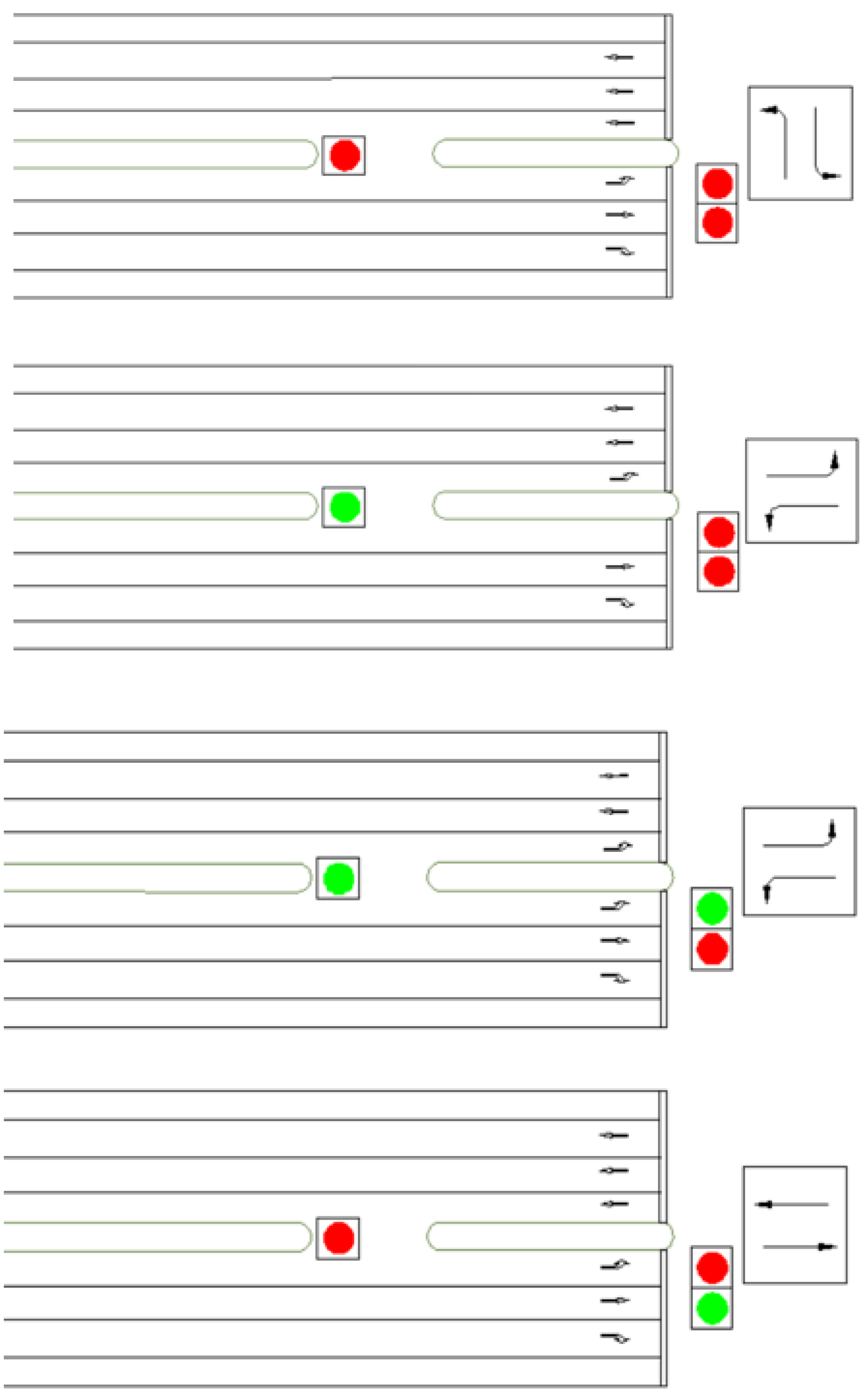
Among them, the exit-lanes for left-turn (EFL) intersections can effectively improve the capacity and reduce vehicle delays without increasing the road space. The main design idea of EFL is to set part of the exit lane as a mixed-use zone to allow left-turning vehicles to turn into the reverse lane. Additionally, pre-signals are provided at the area openings. The main signal is used for intersection left-turn release control, and the pre-signal is used to control the opening and closing of the reverse lane. In Figure 1, the mixed-use zone switches the beat between the exit lane and the left-turn lane. Coordinated control of the main signal and pre-signal is used to improve traffic in the left-turn lane at the intersection and reduce delays for left-turning vehicles [11].
The following conditions need to be considered in the management strategy of the left turn by lane.
  • To avoid the left-turn traffic from generating new conflict points when driving in the mixed area, it is necessary to advance the left-turn phase timing to the opposite flow straight ahead phase, so as to ensure that the left-turn vehicles using mixed-use lanes do not conflict with the opposite straight ahead vehicles.
  • The pre-signal scheme needs to ensure that: the vehicles in the mixing zone are cleared before the end of the left-turn phase, thus ensuring the steady running of the opposing vehicles. This can be achieved by presetting a reasonable pre-signal end time that is sufficient to clear the vehicles in the mixing zone [12].
According to the above requirements, the pre-signal should be turned on before the left-turn release phase, so that vehicles with left-turn demand can drive into the mixing zone and queue up. Additionally, before the main signal ends and stops the left-turn release, the pre-signal must end to prohibit vehicles from entering the mixed-use zone. These theories are gradually being experimented with in reality. In 2016, the EFL design based on the above timing scheme was piloted in Handan, China, becoming the first city in China to implement EFL intersections, as shown in Figure 2.

2. Literature Review

In conventional left-turn designs, left-turn steering usually requires left-turning vehicles to change lanes, which reduces the throughput efficiency. In an early theoretical study of EFL, Xuan et al. [13]. demonstrated that this scenario could improve capacity significantly while guaranteeing the primary passing rate based on a pre-signal control scheme for mixed-use lanes. Zhao et al. [12]. were the first to develop an overall optimization framework including lane assignment, mixed-use zone length, and signal control parameters. Su et al. [14]. demonstrated the advantages of this design in terms of vehicle left-turn operation and throughput efficiency. In terms of model development, the assumptions and constraints associated with the scheme based on the EFL design of left-turn vehicle conservation, pre-signal opening emptying constraint, and lane length constraint were gradually improved, and the optimization model to maximize the capacity was proposed [3]. Based on the above design ideas, Wu et al. [15]. analyzed the delay of left-turn movement and left-turn capacity to optimize the location of the median opening and signal timing of the pre-signal. While the basic model was improved, optimization studies were gradually carried out, and Liu [16] proposed a shock wave-based optimization method to estimate the maximum left-turn queue length by adding consideration of the unique queuing behavior at the pre-signal. Zhao et al. [17]. proposed field data-based EFL control to improve the operation of EFL intersections, and further developed a driving signal control strategy. Chen et al. [18]. performed robust optimization of intersection signal control and conducted extensive research in the case of fluctuating traffic demand at conventional intersections to obtain the most suitable control scheme for different traffic volumes. For the study of traffic signal control, Heydecker [19] studied the effect of traffic fluctuation on signal timing and formed a set of suitable control schemes to minimize the average delay; Ribeiro [20] proposed a new control scheme with better generality, and the TRANSYT test results showed that the scheme has good performance in the fluctuation of traffic flow. Considering the traffic demand fluctuations, Park and Kamarajugadda [21] proposed a dynamic signal control method based on a genetic algorithm, and the simulation results of CORSIM showed that this method has better robust performance than the SYNCHRO control scheme. Yin [22] proposed three robust optimization schemes that can adapt well to traffic fluctuations. Based on these studies, Li et al. [23] applied the EFL model, improved the solution algorithm, and proposed a discrete modeling approach to obtain the global optimal solution by transforming the problem into a binary integer program. Tong et al. [24] proposed a stochastic programming model to optimize adaptive signal control. By comparing with the traditional EFL deterministic linear programming model, it was found that the application of the stochastic programming model can reduce the total vehicle delay and queue length and improve the throughput. A robust optimization model for the integrated design of lane assignment and signal timing at isolated intersections was proposed by Yu et al. [25]. A pre-signal timing robust optimization model for unsaturated intersections was proposed by Hao et al. [26]. In terms of the effectiveness of the design, the research team [14] demonstrated through simulation experiments that the method is effective in improving left-turn capacity and reducing intersection vehicle delays under high left-turn demand. On the other hand, in the work related to the safety of EFL design, researchers used a high-simulation driving simulator to simulate the driving behavior of vehicles applying EFL design and standard markings at intersections. The results suggest that driver confusion can be eliminated by promoting and demonstrating an introduction to EFL use. Additionally, drivers unfamiliar with the borrowed lane rule can use the regular left turn lane to make a left turn. Therefore, the application of EFL does not pose a significant safety issue. However, there are limitations to the simulation, and a large amount of field data still needs to be analyzed for applicable conditions and implementation prerequisites [27]. Currently, the EFL design has been implemented in several cities in China, such as Jinan, Handan, and Shenzhen. The field data provided by these cities allow the potential safety performance of left-turn maneuvers to be evaluated. The results show that the risk stemming from violations or speeding/under-speeding still exists at EFL intersections. However, it can be offset by providing information about the intersection and penalizing the violating operation [28]. To improve the operation of EFL intersections, Zhao et al. [17] proposed a saturation flow regulation model for EFL control based on the field data and further developed a driving signal control strategy. To evaluate the safety, first Wu et al. [29] analyzed the driver’s response to this design under various traffic signs and markings using a high-fidelity driving simulator. The results showed that this design was unlikely to pose a serious safety risk, although drivers were generally confused and hesitant when encountering an EFL intersection for the first time. Based on this, Zhao et al. [30]. evaluated the safety using empirical data. The results showed that potential safety issues at EFL intersections mainly include a high percentage of red light running, wrong-way violations during peak periods, and low speeds in mixed-use areas. However, these risks could be mitigated by providing more guidance information and increased enforcement, such as installing cameras to investigate violations. Among the existing signal control methods to address traffic fluctuations are several approaches, including robust signal control, drive control, and adaptive control.
To summarize the above development process, the overall feasibility and safety of the EFL design have been tested comprehensively from conception to practical application, and the corresponding modeling simulation and data analysis are also very comprehensive. Scholars have also done a lot of research in model construction; from the earliest capacity model to the subsequent development of optimization models and analysis of delay, throughput rate, and other indicators, the model has gradually improved, but the shortcoming is that the applicability of EFL design is relatively limited, and the “heavy congestion of left-turn traffic” is the premise of most of the model construction, The intersection service level and tailpipe emission are less considered. On the other hand, the correlation study between EFL design indicators is still not comprehensive, including the length of the borrowing lane, pre-signal distribution, and other design indicators; and traditional traffic indicators are missing. This paper intends to investigate the correlation between pre-signal distribution and intersection indicators by changing the pre-signal distribution and improving the evaluation of the service level of applied intersections based on the consideration of the original signal control scheme, queue evacuation time of left-turning vehicles, saturation, capacity, and other indicators.
At present, EFL optimization schemes are mostly used to optimize congestion at oversaturated intersections. To maximize the relief of oversaturation, the optimization objective of EFL is to obtain the maximum capacity during the effective green light period, and the optimization scheme can maximize the reduction of intersection saturation and achieve the purpose of oversaturated intersection optimization. According to the research results, the intersection control design should be matched with an appropriate duration of passage, so that the capacity is slightly higher than the traffic demand while minimizing the delay, number of stops, fuel consumption, and other indicators, to ensure the smooth flow of vehicles and reduce operating costs. This paper mainly considers the premise that intersection congestion is effectively improved after the EFL optimization scheme is adopted, and the major priority in the objective setting is the service level of the intersection. Based on this, this paper proposes to take delay as the optimization objective under this condition and re-propose the corresponding constraints for the analysis of delay.
In addition to the innovative ideas of the article, in terms of content, this studycompares with more classic articles of the same kind in recent years. The optimization model, improvement effect, research method, analysis and evaluation, and sustainability are considered, as shown in Table 1. Compared with similar articles, the research in this paper is richer in content, especially in pre-signal timing and sustainability research.
By analyzing the intersection traffic flow operation characteristics, establishing a graph theory model with peak hourly flow and design traffic flow, and also analyzing the traffic delay of left-turning vehicles, we derive and establish an optimization model of traffic delay at signalized intersections, calculating the average delay of left-turning vehicles under different pre-signal control schemes in the saturation state and determining the optimal pre-signal control scheme. This study can provide a theoretical basis for the planning and design of urban signal-controlled road intersections, thus improving the level of urban road traffic service, relieving road traffic congestion, and improving urban road traffic planning and management in general.
3. EFL Solution Design

This section provides a concise and precise description of the experimental results and their interpretation, as well as the experimental conclusions that can be drawn.

3.1. Setting Conditions

Assumptions

  • The original intersection is oversaturated mainly due to excessive left-turn traffic, and the intersection can be improved by developing an unsaturated intersection by EFL optimization, which is assumed to be added to the subsequent delay model establishment in the form of constraints.
  • Set the pre-signal duration as the effective pre-signal duration, without considering the driver’s reaction time and vehicle start-up time.
  • The arrival of left-turning vehicles conforms to the uniform distribution, and the behavior of left-turning vehicles through the intersection conforms to the uniform distribution.
  • After the pre-signal is turned off, the vehicles in the mixed-use lanes can still empty and do not affect the operation of other traffic flows at the intersection.
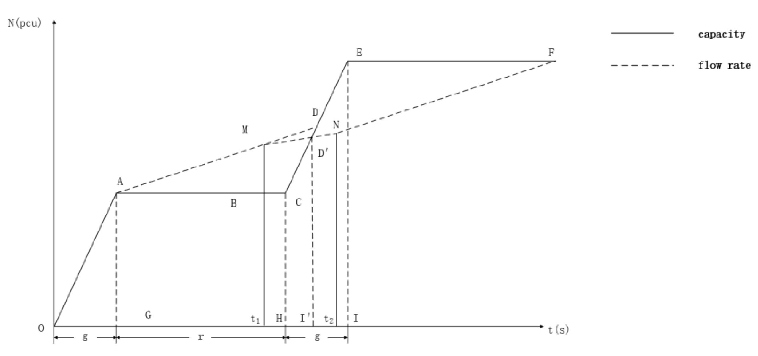
According to the setting conditions of the left-turn borrowing strategy, when the left-turning traffic is borrowing the lane, it is necessary to ensure that the vehicles driving in the opposite direction are emptied before the pre-signal starts, and the delay is minimized as the goal for the optimal configuration of the pre-signal. Let the pre-signal opening moment be t1 and the ending moment be t2, then the traffic flow delay changes as shown in Figure 3.
In Figure 3, The horizontal coordinate indicates the time, including the effective ban and release time; the vertical coordinate indicates the number of vehicles. The solid line represents the roadway capacity and dashed line the left-turn traffic rate.
The straight line AM represents the left-turn flow rate, and the straight line MN represents the flow rate that changes during the pre-signal opening. In contrast, the solid line CE represents the road capacity after the release. When the dissipated traffic flow is the same as the accumulated traffic flow, MN and CE intersect with point D′. Currently, the queue is completely dissipated and subsequent vehicle operations do not incur delays. In this periodic queuing and dissipation behavior, the traffic delay time of a single cycle can be expressed as the area of polygon ACD′M. The above is a simple analysis of the delay model for a single-case EFL design. The specific analysis of the model and the model study based on it are presented in the subsequent section.
It is worth mentioning that the classical graph theory model is used in the delay analysis of this paper. The model draws a line graph with the operational characteristics of traffic flow and road capacity, and the graph contains traffic information such as flow rate, flow, capacity, and signal duration. The advantage of this model is that it provides a realistic reflection of the traffic operation and queue state, and can accurately represent the characteristics of a certain type of traffic flow. The calculation of delays caused by queues or time-varying congestion is relatively accurate and suitable for macroscopic delay analysis. In EFL design, the delay analysis diagram can properly represent the flow rate change after adopting the opposite direction using lanes.

3.2. Modeling

3.2.1. Constraint Analysis

(1) Based on vehicle driving safety, vehicles must all leave within one main signal left turn green light time; the queue length on the traditional left turn lane at the intersection should exceed the length of the borrowed lane. Fluctuation theory derived from the minimum constraint of this left turn flow is applied
Q 1 n k 1 k 2 L T 1
Q1 is the left-turn peak hourly flow rate before the mixed-use area is opened (for the convenience of calculation, the unit of flow rate here is unified as pcu/s, the same below; n is the number of lanes of the left-turn lane; k1 is the blockage density of the intersection (pcu/m); k2 is the density of left-turn traffic upstream of the intersection (pcu/m); L is the length of the mixed-use area (m); T1 is the time when the red light is turned on from the pre-signal (s).
(2) After EFL optimization, the intersection is not saturated; left-turning vehicles can complete the turn in a single cycle, that is, to meet the left turn once through, mixed-use lanes and left-turn lane maximum through vehicles should be greater than the left-turn demand.
Q 1 · C N + n · Q 1 · t 2 g r / n + 1 S · t g
C is the full cycle duration of the intersection (s); N is the maximum number of vehicles that can stop in the left-turn lane between the stop line and the pre-signal position; t1 is the pre-signal green light on time (s); t2 is the pre-signal green light off time (s); g is the effective green light duration for left-turn phase traffic (s); r is the effective red light duration for left-turn phase traffic (s); S is the saturation flow of the left-turn lane (pcu/s); tg is the effective green light duration for the main signal (s).
(3) Due to the oversaturation caused by the excessive left-turn demand at the original intersection, the overall congestion at the intersection should be relieved after optimization, and the flow ratio requirement in the traditional HCM model is used as the intersection smoothness criterion to propose constraints [34].
Q 1 Q 3 c < 0.9 Q i c i
c is the left-turn lane capacity (pcu/s); Q3 is the peak hourly flow rate of the left-turn lane (pcu/s) after the mixed-use area is opened. Qi is the peak hourly traffic flow (pcu/s) at phase i of the intersection except for the left-turn phase; ci is the capacity (pcu/s) at phase i of the intersection except for the left-turn phase.
(4) In the EFL signal timing scheme, the pre-signal needs to be set to meet the requirement of opening the mixed-use area in advance as a left-turn lane for vehicles to queue before the left-turn phase starts, so a minimum time constraint needs to be set for the early opening of the green light in the pre-signal timing.
T 1 T 0 + L / v
T0 is the time (s) for the first vehicle to enter the mixed-use area after the pre-signal green light is turned on, and its average value is statistically calculated to be about 2.5 s. v is the average speed (m/s) of the vehicle driving into the mixed-use area.
(5) The program should empty the vehicles in the mixed-use area before the end of the left turn, and vehicles need to be prohibited from driving into the mixed-use area to resume the use of the exit lane; therefore, the minimum time constraint for the early closure of the green light in the pre-signal timing needs to be set for vehicle emptying.
T 2 L / v
T2 is the pre-signal early closing time (s).

3.2.2. Build the Optimization Model

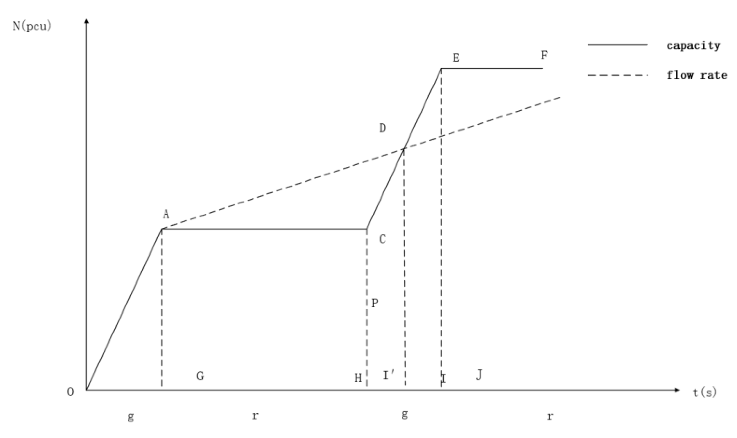
The delay analysis of the left-turn lane is shown in Figure 4. With no EFL set, left-turn vehicles pile up during the red light, i.e., the accumulated vehicles (N) corresponding to the flow rate line AD. After the green light is turned on, the left-turn queue, represented by line CE, begins to dissipate in terms of capacity. When the number of dissipation is balanced with the number of oncoming traffic, the queue is completely dissipated, i.e., line AD intersects CE at the dissipation point D. In this case, the total delay time for left-turning vehicles is the area of the triangle ADC.
Next, we analyze the changes in the model after the introduction of EFL. Compared to the conventional left-turn lane, a pre-signal is added to control the flow. The pre-signal on moment (t1) and pre-signal off moment (t2) are added to the time axis. Depending on the setting of the t2 moment, the models can be classified into two types.
(1)
t2 moment before the original dissipation point (point D)
In this case, as shown in Figure 3, the traffic stops diverging only after the pre-signal is turned off, and the queuing traffic has dissipated by then, i.e., the flow change line MN intersects CE at point D′, thus creating a new dissipation point D′, at which time the total delay area is the area of polygon ACD′M, and the left-turn traffic evacuation time is (I′-H) seconds after the green light is turned on, and it can be seen that both delay and evacuation time are reduced compared with that when the EFL scheme is not set. Model I is as follows:
Objective   function :   m i n Z = S A C D M
Constraints :   Q 1 n k 1 k 2 L T 1
Q 1 · C N + n · Q 1 · t 2 g r / n + 1 c · t g
Q 1 N + n · Q 1 · t 2 g r / n + 1 / C c < 0.9 Q i c i  
g + r t 1 T 0 + L 2 / V 1
2 g + r t 2 L 2 / V 1
g < t 1 < g + r
t I < t 2 < 2 g + r
t 1 . t 2 > 0
Above, the delayed area in the objective function is parametrically calculated as:
m i n Z = Q 1 · T 1 2 2 + T · Q 1 · T 1 + Q 2 · T 2 c · T 3 2 2 + c · Q 3 · T 1 2 2 c Q 3
T is the effective duration of the pre-signal (s); T3 is the pre-signal on the moment from queue dissipation (s); Q2 is the peak hourly flow rate of the mixed-use area (pcu/s) after the mixed-use area is opened.
(2)
t2 moment after the original dissipation point (point D)
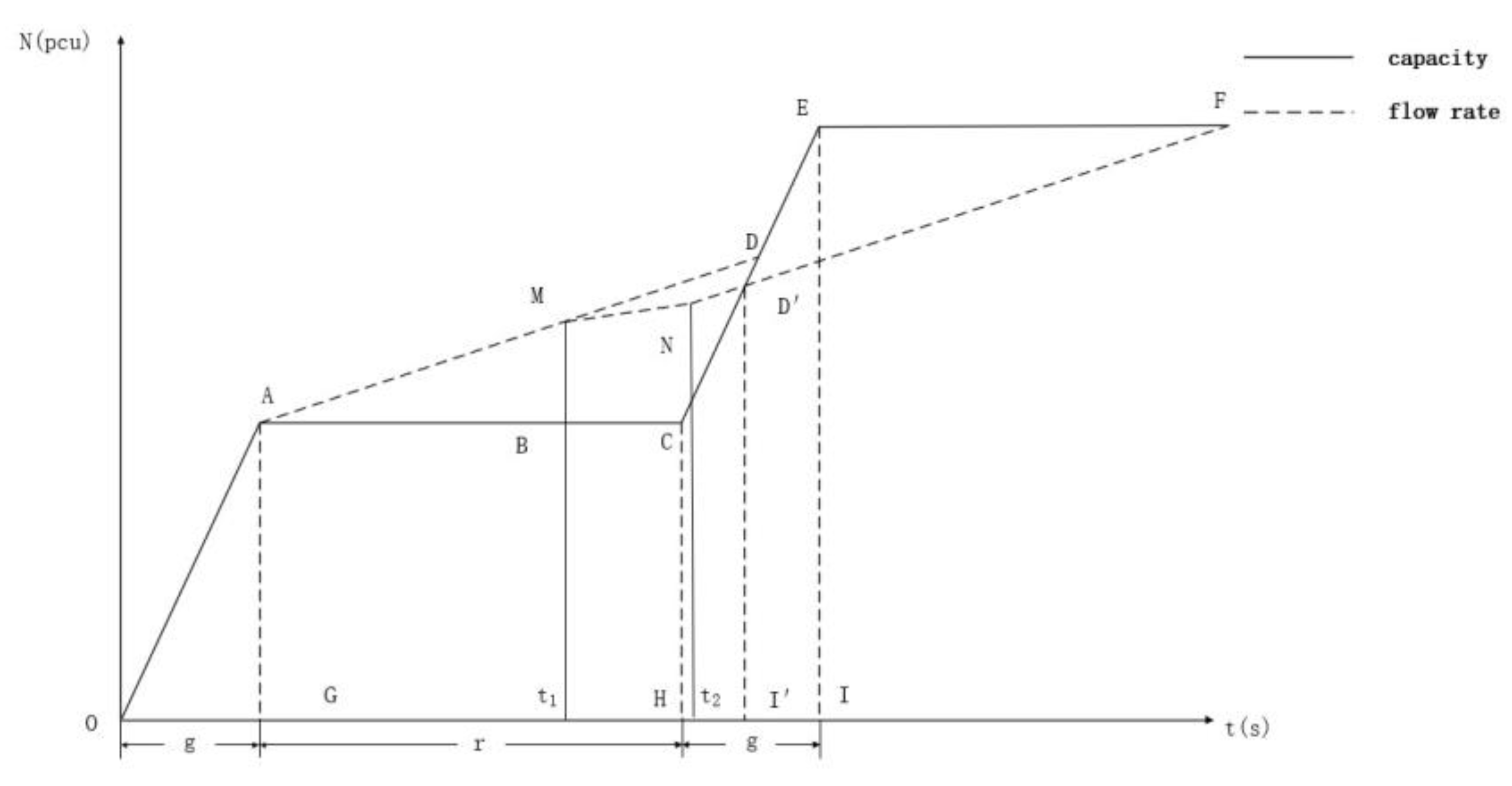
In this case, the traffic stops diverging only after the pre-signal is turned off, as shown in Figure 5, while the queuing traffic still has not dissipated and continues to queue with the original flow. At this time, the flow is connected to the original flow line NF after the diversion line MN, and the original flow line NF intersects CE at point D′, thus creating a new dissipation point D′. At this time, the total delay is the area of polygon ACD′NM in Figure 5, and the left-turn traffic evacuation time is after the green light is turned on (I′-H) seconds; and similarly, it can be seen that the delay time decreases with the evacuation time.
Based on the image, the model II is constructed. In this case, the objectives and some constraints of the model are changed, and the following are the objectives and constraints changed in Model II.
Objective   function :   m i n Z = S A C D N M
g + r < t 2 < t I
The remaining constraints of model II are the same as the previous Equations (7)–(12) and (14).
The delayed area in the parametrically calculated objective function is as follows:
m i n Z = Q 1 · T 1 2 2 + T · Q 1 · T 1 + Q 2 · T 2 + T 3 · 2 Q 1 · r + 2 Q 2 · T Q 1 · T 3 2 c · T 4 2 2 + c · Q 3 · T 1 2 2 c Q 3
T4 is the green light on the moment from the queue dissipation time (s).
Subsequently, the optimal solutions of the two models need to be compared to determine the optimal solution for the pre-signal onset time of the left-turn traffic.

4. Model Validation

4.1. Subjects and Preparation of Experiments

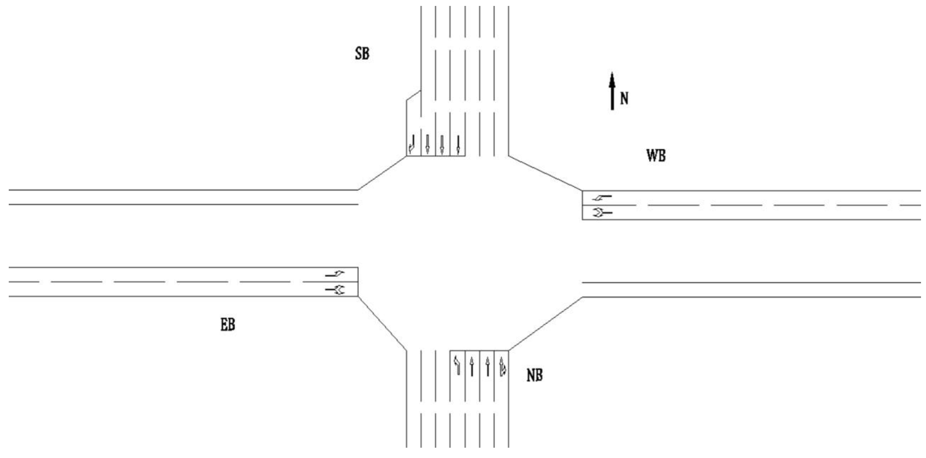
In this paper, the exit-lanes for left-turn traffic pre-signal timing optimization analysis is carried out at the Shikui Road/Jiefang Road intersection (Figure 6) in Zhongshan District, Dalian City, for example.
The basic road information of the intersection is shown in Figure 6. The intersection is formed by the intersection of Jiefang Road, a main road flowing north-south, and Shi kui Road, a secondary trunk road flowing east-west. There is a viaduct (Shiqui Bridge) in the east-west direction, and its pillars partially occupy the roadway area of Shiqui Road, but this has no impact on the normal operation of the intersection. The intersection uses three-phase signal control, with the set EFL program conditions. On the other hand, the north-south flow of the road for two-way eight lanes, taking into account the road resources and surrounding bridge facilities factors, is suitable for the use of EFL design for optimization.
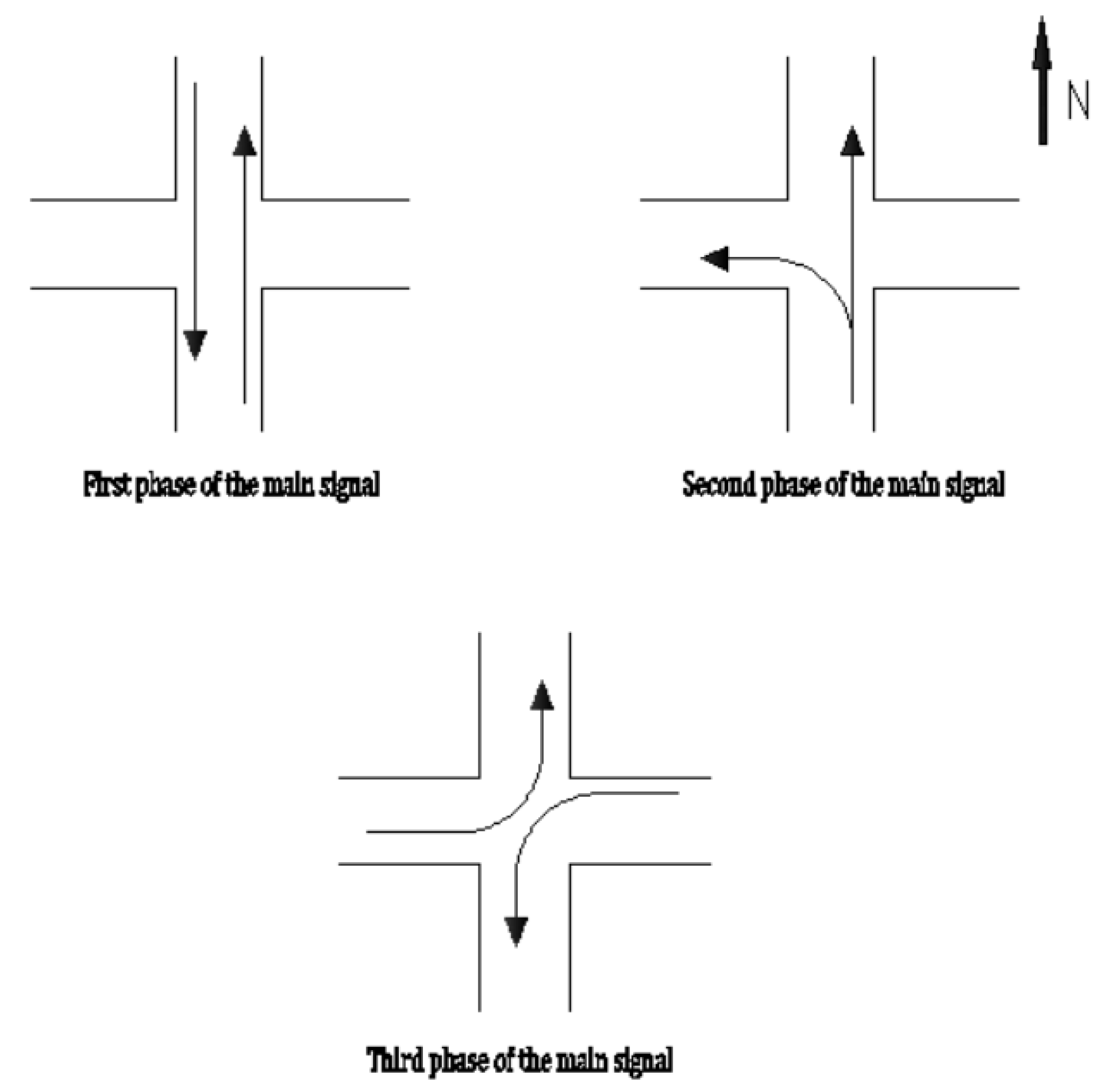
The intersection adopts the three-phase timing scheme of the delayed left turn, and the phase and timing diagrams are as Figure 7 and Figure 8:
The information on the intersection’s timing phase scheme is as follows:
The South import left turn passing phase display green light duration is 100 s. The straight-line phase shows the green light for 50 s. The intersection yellow light duration is 3 s. The full cycle duration is 304 s in total. The phase control scheme of the intersection meets the premise assumptions of the model and has an application basis.

4.1.1. Investigation and Estimation

We investigated the evening peak flow by vehicle at the intersection during 17:00–19:00 h on 13 June 2022 (workday). The survey was conducted with a 5-min counting period. In the processing of the data, motor vehicles were converted to passenger car units (pcu). The sum of the traffic volumes for adjacent cycles was calculated sequentially as the peak 15-min selection. From there, the peak hourly flow rates for each lane at the intersection were determined.
Additionally, we observed the saturation headway of vehicles at the intersection during the same period. For convoys longer than 10 pcu, the vehicles after the 5th vehicle in the convoy after the start of the release were used as the observation targets. The sample size for each lane was 3, and the headway statistics were averaged. Following the Highway Capacity Manual, the base saturation flow was estimated with the formula:
S bi = 3600 h 0
Sbi is the basic saturation flow (pcu/h); h0 is the saturation headway time distance(s), which is the time interval between the headways of two vehicles traveling continuously through a location. The data for each lane investigated above are shown in Table 2.
After investigating the traffic flow along the intersection during peak hours and analyzing the flow data, it is found that during the morning and evening peak hours, there is traffic congestion caused by excessive left-turn traffic flow, and the saturation of the left-turn lane at the south entrance is large, which is the main cause of congestion at the intersection and meets the application conditions of the model.
The formula for estimating the capacity of each lane is as follows:
S f = S bi × f F i  
Sf indicates the design saturation flow of the import lane(pcu/h); Sbi is the basic saturation flow of the i-th import lane(pcu/h); f (Fi) is various correction factors for various types of import lanes.
The following design saturation flow equation for the left-turn lane, using the South left-turn lane as an example, is:
S L = S bL × f g × f W × f r
SL is the design saturation flow of the left turn lane (pcu/h); SbL is the basic saturation flow of the left turn lane (pcu/h); fg is the correction factor for heavy vehicles. fw represents the lane width correction factor; fr denotes the turning radius correction factor.
The observed average left-turn headway was 3.38 s, with a basic saturation flow of about 1064 pcu/h. The correction factor for heavy vehicles can be calculated as follows:
f g = 1 HV
where HV represents the ratio of heavy vehicles. In the survey conducted, the average heavy vehicle rate in the left turn lane was 3.36%. The correction factor for heavy vehicles was 0.966.
The lane width factors are next formulated with the following intervals:
f w = 0.4 W 0.5 1 0.05 W + 16.5
W is the width of the lane (m). These are the corresponding values for widths of 2.7–3.0 m, 3.0–3.5 m, and not less than 3.5 m, respectively. In practice, the width of the left-turn lane is 3.5 m. The coefficient takes 1.
The left turn radius of the vehicle is 20 m and the correction factor is 0.97. Table 3 provides the specification table concerning the manual.
At this point, we have completed the calculation of the design saturation flow. The left turn lane is 997 pcu/h. Converting this to capacity:
c = S f × λ
λ is the Phase splits, i.e., the ratio of release time to signal period. The left-turn release occupies 32.89%. The left-turn lane capacity is 327 pcu/h. Table 4 shows the capacity (pcu/h) and congestion status of each lane.
From the table, it can be seen that the congestion problem at the intersection is mainly concentrated in the northbound left-turn lane and the saturation is within the controllable range. The basic assumptions of the model application are met. The EFL design and model experiments are performed next.

4.1.2. Program Design

The main points to consider in the design solution are driver safety and adaptability. On this basis, the assumptions needed for the model are added. Depending on the congestion of the left turn, excessive use of the opposite lane is unnecessary and risky. Therefore, a southbound exit lane near the roadway median was designed as an EFL lane.
Based on existing experience, it is acceptable and safe for drivers to enter mixed areas in urban roads with openings 25 m or more from the stop line. The long opening reduces the possibility of incorrect operation. On the other hand, in the model assumptions, it is required that the mixing area can accommodate all incoming vehicles. We set the opening at 60 m from the stop line and set a prominent pre-signal.
In addition to this, in practice, some measures are recommended to reduce driver uncertainty.
  • Place a hanging guide sign 25 m from the opening of the road, every 5 m.
  • At the beginning of the application, place speed bumps on the road before entering the mixing area.
  • Add guide markings on the road for the exit lane for left-turn lanes.
  • At the opening, the guardrail uses an automatic guardrail with pre-signal coordination control.
  • Add a dedicated signal light directly above the exit lane for left-turn lanes, synchronized with the left-turn control light.
  • Set reminder signals before the pre-signal opens and ends, such as flashing lights, countdown timers, etc.
The above measures can give drivers more sufficient time to obtain more complete information. Keeping drivers safe and reducing the accident rate should be the primary consideration in the application.

4.2. Model Application

The example parameters of the left-turn lane at the northbound of Jiefang Road are input and the delays are calculated for it, and the total delays of the left-turn lane without optimization are as follows:
d = S A C D = 204 · 289.756 · 0.1267 2 = 3744.6 s
The left-turning vehicles are delayed as follows:
d ¯ = d n = 102 s
Statistically, the percentage of left-turning vehicles at the intersection was 14.3% for new energy vehicles. The rate of medium-duty and heavy-duty vehicles is 3.36%. The percentage of left-turning light-duty cars except for new energy vehicles is 82.8%. Calculate the emissions of standard vehicles:
The total tailpipe emissions due to delays of left-turning vehicles Δp are as follows [35,36,37]:
Δ p = p S + p D + p I
pS is the emission when the vehicle stops until it returns to its initial speed; pD is the emission when the vehicle decelerates until it returns to its initial speed; and pI is the emission when the vehicle’s engine is idling. The emissions of the three components are calculated as follows:
p S = Q · m · E = 3.09 kg
Q is the volume of traffic corresponding to the lane (pcu/h): m is the stopping percentage of arriving vehicles; E is the additional emissions corresponding to the change in speed per kilometer (kg/pcu).
p D = T D · Q · E T O = 2.48 kg
TD is the delay time from vehicle deceleration (s); TO is the delay time from speed change per km (s).
p I = T s · Q · E I = 5.78 kg
TS is the stopping delay time per vehicle (s); EI is the emission rate when the vehicle engine is idling (g/pcu∙min).
The total emissions caused by the delay of left-turning light-duty vehicles at the intersection is 11.35 kg.
Of the other vehicles turning left, 46.67% were medium-duty vehicles and 53.33% were heavy-duty vehicles. Relevant studies [38,39,40] were referenced for the total emission ratio of different vehicle models under the same speed and environment. The emissions of this part of medium-duty and heavy-duty vehicles is about 4.67 kg. The estimated emissions and percentage by vehicle type are shown in Table 5.
The total left-turning vehicle emissions affected by the delay at the intersection is approximately 16.02 kg.
Above are the left-turn vehicle delays and emissions for the existing intersection. In the optimization model, the part of the delay is obtained in the target, and the emissions can be further obtained by the optimized parameters of delay, acceleration, and deceleration vehicles.
To divert the queue earlier, in Model I, we extend the release time of the opposite lane and always keep the pre-signal closure time after the queue dissipation time. In Model II, we always keep the pre-signal closure time before the queue dissipation time. And in pursuit of more rapid evacuation, interestingly, this brings a series of changes including target areas, constraints, and delay calculations. On the other hand, the pre-signal control periods and dissipation moments are constantly changing with the need to reduce delays in both cases, and this change is complex, unpredictable, and non-linear. In the assumed ideal case, by experimenting with existing intersections, we analyze the validity of the model and variation of various parameters in them.
We implemented EFL optimization for the above study intersection by making an opening in the median 60 m from the south inlet stop line and using the inner exit lane corresponding to the open section as a mixed-use area. The maximum number of vehicles stopped in the area is about 12, and the average roadway speed is taken as the measured value of 6 m/s. In the survey of this fleet, the clogging density was 0.20 pcu/m and the evacuation density was 0.16 pcu/m. The intersection parameters are applied to the above delay model. In Model I, the queuing dissipation time (tI) is represented as follows:
t I = c · C + t 1 Q   1 Q   2 Q   1 · g c Q 2
The corresponding objective functions and parameters in the model are calculated as follows:
m i n Z 1 = 0.06335 t 1 100 2 + t 2 t 1 · ( 0.0082 t 1 12.667 + 0.1185 t 2 0.0002084 t 2 2 + 0.0002084 t 1 t 2 ) 0.2141 · 0.0004168 t 1 t 2 0.1103 t 1 0.1267 t 2 + 59.378 0.1911 + 0.0004168 t 2 2 + 0.2141 · 0.0004168 t 2 0.1103 · 304 t 1 2 0.5384 0.0004168 t 2
t 1 118.9
t 2 > 326.2
t 1 291.5
t 2 394
100 < t 1 < 304
117.472 < 0.0004168 t 2 2 0.0004168 t 1 t 2 + 0.1911 t 2 + 0.1133 t 1
The above model is solved iteratively by using non-linear programming in MATLAB. The optimization results are as follows: t1 is 183.3 s, and t2 is 372.5 s. The mixed-use area is opened for left-turn vehicles to queue at 83.3 s after the start of the left-turn prohibited phase. The vehicles are prohibited from entering the mixed-use area at 68.5 s after the start of the left-turn released phase, and the pre-signal release time is 189.2 s. The corresponding average delay of the left-turn lane is 87.6 s. An intuitive pre-signal control scheme for model I is shown in Figure 9.
In Model II, the queuing dissipation time is represented as follows:
t I = t 2 · Q   2 Q   1 Q   2 · t 1 + Q 1 · t 1 g + c · C c Q 1
The objective function and constraints are calculated as follows:
m i n Z = 0.06335 · t 1 100 2 + t 2 t 1 · ( 0.0002084 t 1 t 2 0.0002084 t 2 2 + 0.0082 t 1 + 0.1185 t 2 55.48 ) + ( 0.0006584 t 1 t 2 0.0006584 t 2 2 0.3744 t 1 + 0.5544 t 2 13.884 ) · ( 0.0006914 t 1 t 2 0.0006914 t 2 2 0.3932 t 1 0.0349 t 2 + 258.774 ) 2.356 · ( 0.0004168 t 1 t 2 0.0004168 t 2 2 0.237 t 1 + 0.1103 t 2 + 64.364 ) 2
t 1 118.9
t 2 > 326.2
t 1 293.167
t 2 395.667
100 < t 1 < 304
0.0004168 t 2 2 0.0004168   t 1 t 2 + 0.237 t 1 + 0.1911 t 2 < 64.364
After solving, the optimal results are: t1 takes 239.1 s, and t2 takes 326.2 s. The opening of the mixed-use zone for left-turning vehicles to queue is at 139.1 s after the left-turn prohibited phase. After 22.4 s of the left-turn phase opening, left-turning vehicles are prohibited from entering the mixed-use area. The pre-signal release time is 87 s. The corresponding average delay of the left-turn lane is 86 s. The pre-signal timing diagram for model II is shown in Figure 10.
Comparison of the results of the above two solutions in Table 6:
In the experimental comparison of the above two models, the pre-signal of model I on the moment is earlier, and the off moment is close to the queue dissipation moment. The EFL is open for a more extended period. In contrast, the model II mixing area is open for a shorter period, closing the entrance to the exit lane before the queue dissipates.
In model I, the prolonged use of the mixing zone makes the diversion effect stronger. The average vehicle delay is reduced by 14.1% from 102 s to 87.6 s. At the same time, the total emissions changed from 16.02 kg to 14.37 kg. In model II, the open time of the mixed-use area is shorter. After the pre-signal is turned off, the emptying time in the opposite lane is close to the main queue dissipation time, making full use of the EFL evacuation capability. The average vehicle delay was reduced to 86 s, a decrease of 15.7%. Total emissions dropped to 14.19 kg, a 11.4% reduction. In both models, there is a large improvement in capacity and delay, but the benefits differ. With sufficient capacity, the benefits of model 2 are more substantial in terms of delays and emissions compared with model 1.
Through the above model comparison, it can be concluded that in the EFL design, the delay gain is related to the queue dissipation time corresponding to the set pre-signal on/off moment; and based on the actual traffic data, the delay gain of the EFL application can be improved by setting a reasonable pre-signal control scheme concerning the queue dissipation time. When designing EFL for intersections with the goal of delay minimization, the pre-signal off time should match the queue dissipation time as much as possible. On the other hand, the pre-signal start time should not be too early, and too long a control time may cause a reduction of delay improvement effect.

4.3. Comparison of Fleet Energy Types

This section investigates the relationship between fleet operation and EFL delays. The operating characteristics of different models, such as start-up acceleration, average vehicle speed, and delayed reaction time, are considered. A total of 385 vehicles approaching the intersection during the evening peak were surveyed during a 5-min period and categorized according to the main types of energy used. The main types are traditional ICE vehicles (ICEV) and new energy vehicles; the latter can be divided into plug-in hybrid vehicles (PHEV) and battery electric vehicles (according to the different energy sources). Next, the saturation headway of three sample fleets in the left-turn lane was investigated by types during the same time period [41], and the results are shown in Table 7.
Statistically, the headway of ICEV is larger with a mean value of 3.31 s. The PHEV is more dynamic and stable, with a shorter average headway of 2.56 s. Pure electric vehicles start lighter and faster, with an average headway of 2.78 s.
To better study the operating characteristics of different types of convoys and their adaptability to the model, we assume that the left-turning vehicles are all of the same type. Keeping the peak flow rate and facilities such as lanes unchanged, the model parameters such as capacity of the above three types of convoys are calculated separately. The type of parameters is shown in Table 8:
Substituting the parameters into the models to solve for them, the results for each type of fleet delay are shown in Table 9.
It is clear from the results that the types of fleets have a degree of influence on the delays generated. In the optimization results of the EFL model, the average delay of the new energy fleet is smaller. Of these, the delays for the pure electric and plug-in hybrid fleets decreased by 1.72% and 7.72%, respectively, compared with the conventional internal combustion engine fleet. This suggests that choosing a more powerful model can speed up the dissipation of the queue and thus reduce the overall delay time. On the other hand, it can also be found that the effect of changing the capacity on delays is not very significant when the left-turn flow in the EFL is tolerable.

4.4. Sensitivity Analysis

In this paper, the total traffic flow delay model is established by considering various factors, and the corresponding solution method is designed. Finally, the established model is applied to the specific problem. To further explore the internal laws of the model, this paper uses the peak flow rate as the variable for sensitivity analysis, and the peak flow rate is taken to range from 400 pcu/h to 600 pcu/h with an increased step of 10 pcu/h for the delay calculation, and the results of model I are shown in Table 10.
The results of model II are shown in Table 11.
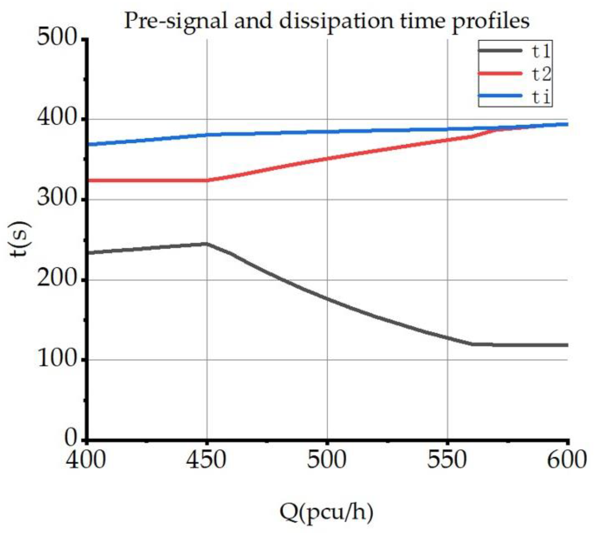
With the peak flow rate as the independent variable, the optimal values corresponding to the pre-signal on moment t1, pre-signal off moment t2, and queue dissipation moment ti are calibrated, respectively, and the flow rate/time chart of Model I is plotted in Figure 11.
It can be observed that as the flow rate continues to increase, the queue dissipation moment is continuously delayed, while the optimal closing moment t2 of the pre-signal is always consistent with the dissipation moment ti until the peak flow rate reaches 570 pcu/h and the optimal closing moment reaches the upper bound of 394 s, while the dissipation time continues to increase; at the peak flow rate in the lower range of 400 pcu/h–560 pcu/h of the pre-signal, the optimal opening moment t1 changes more steadily, and as the flow rate increases further, the optimal opening moment starts to move forward significantly to ensure the delay gain after the pre-signal closing moment reaches the upper bound, until the flow rate reaches saturation at 600 pcu/h, and the opening moment is 118.9 s.
The flow rate/time chart for model II is calibrated as shown in Figure 12.
Distinguished from model I, model II is more sensitive to changes in flow rate. In the lower flow rate interval of 400–450 pcu/h, the optimal case of the pre-signal closing moment takes the lower bound of 324 s. While the opening moment takes the value of the upper bound corresponding to the vehicles in the lane that can be cleared, and the total pre-signal duration takes the minimum. With the increasing flow rate, the optimal closing moment of the pre-signal is close to the queue dissipation moment until the flow rate reaches 600 pcu/h, optimal closing moment reaches the upper bound of 394 s, and intersection reaches saturation; while the optimal opening moment of the pre-signal t1 keeps decreasing and reaches the lower bound at 570 pcu/h.
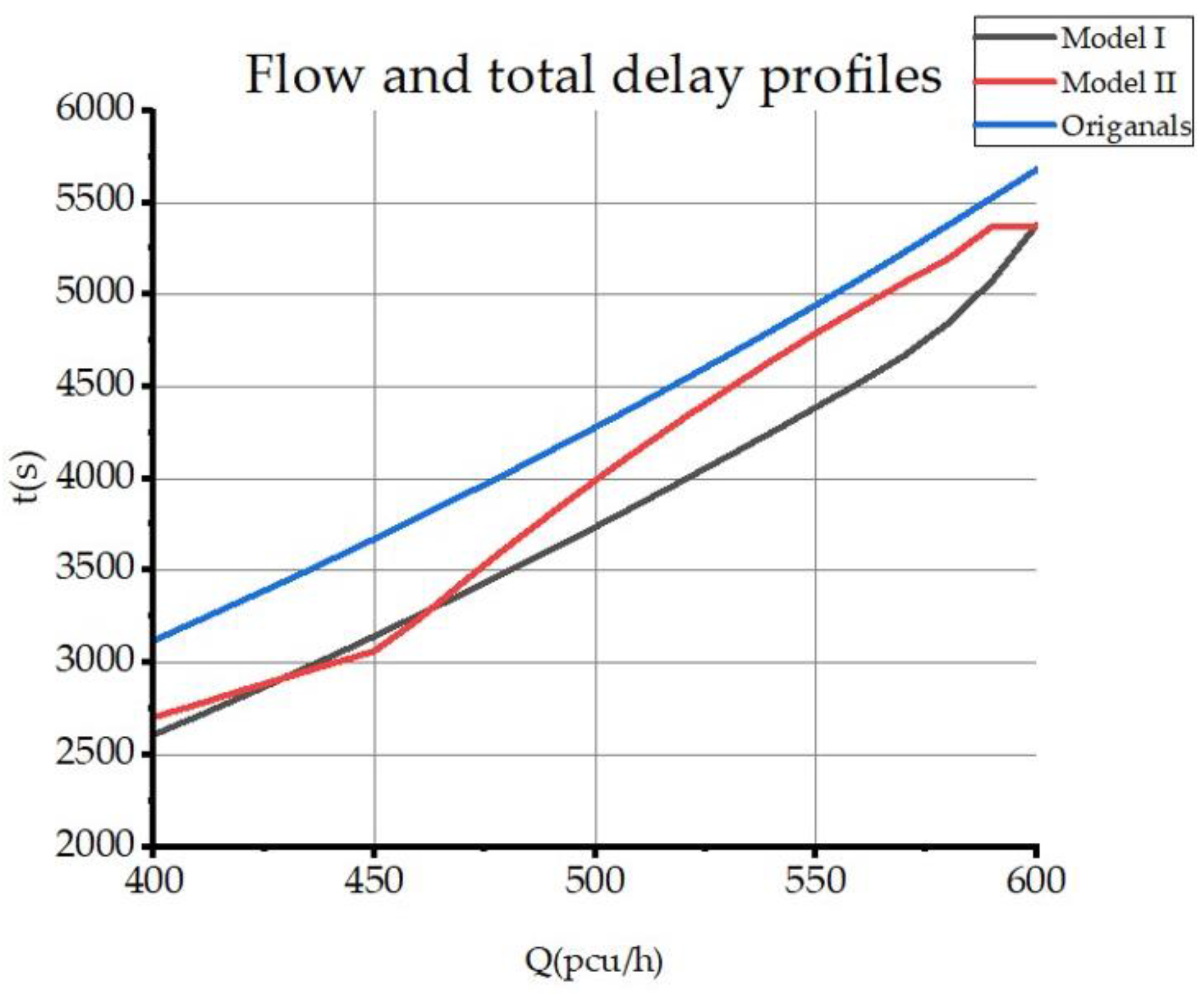
In the case of flow variation, the trend of delay benefits for both models is shown in Figure 13. Compared with model II, model I has a longer pre-signal on time, but it can be found from the experimental data that the delay reduction gains of model I and model II are not much different when the flow rate is low; and when the flow rate increases further, model I with the pre-signal off time set after the queue dissipation time has a better effect, while model II with the pre-signal off time set before the queue dissipation time has relatively more significant impact when the intersection flow is close to saturation.

5. Conclusions

With the model assumptions satisfied, the implementation of EFL resulted in a 15.7% reduction in total left-turn vehicle delay, along with an 11.4% reduction in fleet emissions and a 65.7% increase in left-turn capacity. The delay model constructed in this paper is valid. Additionally, the following conclusions can be drawn from the above study:
  • From the experimental model comparison, model I, which has the better capacity, lags behind model II in terms of delay reduction. In EFL design, a pre-signal scheme that more significantly increases capacity does not necessarily minimize fleet delays.
  • From the experimental results and subsequent fleet-type comparisons, it can be seen that the adjustment for adequate capacity has a limited degree of impact on delays at lower flows. To effectively reduce delays, in the EFL design, if the intersection is not saturated after design, the design of the pre-signal control and queue dissipation time should be considered.
  • It can also be seen from the comparison of the operation of different vehicle types: the operational status of the fleet can be considered in EFL, and higher powered vehicles with faster start-up (e.g., plug-in hybrids) can help speed up fleet evacuation.
  • The following conclusions were drawn from the dual model comparison at different flow rates. The pre-signal closure time will be designed to fit and precede the queue dissipation time as much as possible, which will reduce the average vehicle delay when evacuating queued vehicles.
  • From the sensitivity analysis, it is found that in many cases, longer pre-signal open time is not ideal for delay reduction. The pre-signal design time should not be too long. Based on the actual flow of pre-signal timing, designing a reasonable application time can obtain a higher delay reduction effect.

Author Contributions

Conceptualization, B.F. and M.Z.; data curation, B.F.; formal analysis, B.F.; investigation, B.F.; methodology, B.F.; project administration, Y.L.; software, B.F.; validation, B.F.; visualization, B.F., M.Z. and Y.L.; writing—original draft, B.F. and M.Z.; writing—review & editing, M.Z. and Y.L. All authors have read and agreed to the published version of the manuscript.

Funding

This research received no external funding.

Institutional Review Board Statement

Ethical review and approval were waived for this study due to the studies not involving humans or animals.

Informed Consent Statement

Patient consent was waived due to the studies not involving humans.

Data Availability Statement

The source of all traffic data at the intersection used in this paper is the actual field survey in Dalian, Liaoning Province. The author guarantees the authenticity and reliability of the data used in the validation section.

Conflicts of Interest

The authors declare no conflict of interest.

References

  1. Jagannathan, R.; Bared, J. Design and Operational Performance of Crossover Displaced Left-Turn Intersections. Transp. Res. Rec. 2004, 1881, 1–10. [Google Scholar] [CrossRef]
  2. Suh, W.; Hunter, M.P. Signal design for displaced left-turn intersection using Monte Carlo method. Ksce J. Civ. Eng. 2014, 18, 1140–1149. [Google Scholar] [CrossRef]
  3. Zhao, J.A.; Ma, W.; Head, K.L.; Yang, X. Optimal operation of displaced left-turn intersections: A lane-based approach. Transp. Res. Part C Emerg. Technol. 2015, 61, 29–48. [Google Scholar] [CrossRef]
  4. Hummer, J.E. Unconventional left-turn alternatives for urban and suburban arterials—Part one. ITE J. 1998, 68, 66–69. [Google Scholar]
  5. Liu, P.; Lu, J.J.; Chen, H. Safety effects of the separation distances between driveway exits and downstream U-turn locations. Accid. Anal. Prev. 2008, 40, 760–767. [Google Scholar] [CrossRef]
  6. Jing, Z.; Ma, W.; Head, K.L.; Yang, X. Optimal Intersection Operation with Median U-Turn: Lane-Based Approach. Transp. Res. Rec. J. Transp. Res. Board 2014, 2439, 71–82. [Google Scholar]
  7. Hummer, J.E. Unconventional left-turn alternatives for urban and suburban arterials—Part two. ITE J. 1998, 68, 101–106. [Google Scholar]
  8. Moon, J.P.; Kim, Y.R.; Kim, D.G.; Lee, S.K. The potential to implement a superstreet as an unconventional arterial intersection design in Korea. KSCE J. Civ. Eng. 2011, 15, 1109–1114. [Google Scholar] [CrossRef]
  9. Holzem, A.M.; Hummer, J.E.; Cunningham, C.M.; O’Brien, S.W.; Schroeder, B.J.; Salamati, K. Pedestrian and bicyclist accommodations and crossings on superstreets. Transp. Res. Rec. 2015, 2486, 37–44. [Google Scholar] [CrossRef]
  10. Xuan, Y.; Daganzo, C.F.; Cassidy, M.J. Increasing the capacity of signalized intersections with separate left turn phases. Transp. Res. Part B Methodol. 2011, 45, 769–781. [Google Scholar] [CrossRef]
  11. Chen, K.; Zhao, J.; Knoop, V.L.; Gao, X. Robust signal control of exit lanes for left-turn intersections with the consideration of traffic fluctuation. IEEE Access 2020, 8, 42071–42081. [Google Scholar] [CrossRef]
  12. Zhao, J.; Ma, W.; Zhang, H.M.; Yang, X. Increasing the capacity of signalized intersections with dynamic use of exit lanes for left-turn traffic. Transp. Res. Rec. 2013, 2355, 49–59. [Google Scholar] [CrossRef]
  13. Xuan, Y.; Gayah, V.V.; Cassidy, M.J.; Daganzo, C.F. Presignal used to increase bus-and car-carrying capacity at intersections: Theory and experiment. Transp. Res. Rec. 2012, 2315, 191–196. [Google Scholar] [CrossRef] [Green Version]
  14. Su, P.; Krause, C.; Bared, J.G.; Hale, D.; Bared, J.; Huang, Z. Operational advantages of contraflow left-turn pockets at signalized intersections. In Proceedings of the Transportation Research Board 95th Annual Meeting, Washington DC, USA, 10–14 January 2016; Volume 86, pp. 44–49. [Google Scholar]
  15. Wu, J.; Liu, P.; Tian, Z.Z.; Xu, C. Operational analysis of the contraflow left-turn lane design at signalized intersections in China. Transp. Res. Part C Emerg. Technol. 2016, 69, 228–241. [Google Scholar] [CrossRef]
  16. Liu, Y.; Wong, C.K. Refining lane-based traffic signal settings to satisfy spatial lane length requirements. J. Adv. Transp. 2017, 64, 1–27. [Google Scholar] [CrossRef] [Green Version]
  17. Zhao, J.; Liu, Y. Safety evaluation of intersections with dynamic use of exit-lanes for left-turn using field data. Accid. Anal. Prev. 2017, 102, 31–40. [Google Scholar] [CrossRef]
  18. Chen, Q.; Yi, J.; Wu, Y. Cellular automaton simulation of vehicles in the contraflow left-turn lane at signalised intersections. IET Intell. Transp. Syst. 2019, 13, 1164–1172. [Google Scholar] [CrossRef]
  19. Wong, C.K.; Heydecker, B.G. Optimal allocation of turns to lanes at an isolated signal-controlled junction. Transp. Res. Part B Methodol. 2011, 45, 667–681. [Google Scholar] [CrossRef]
  20. Ribeiro, P.C.M. Handling traffic fluctuation with fixed-time plans calculated by TRANSYT. Traffic Eng. Control 1994, 6, 362–366. [Google Scholar]
  21. Park, B.; Kamarajugadda, A. Development and evaluation of a stochastic traffic signal optimization method. Int. J. Sustain. Transp. 2007, 1, 193–207. [Google Scholar] [CrossRef]
  22. Zhang, L.; Yin, Y.; Chen, S. Robust signal timing optimization with environmental concerns. Transp. Res. Part C Emerg. Technol. 2013, 29, 55–71. [Google Scholar] [CrossRef]
  23. Li, X.; Sun, J.Q. Turning-lane and signal optimization at intersections with multiple objectives. Eng. Optim. 2019, 51, 484–502. [Google Scholar] [CrossRef]
  24. Tong, Y.; Zhao, L.; Li, L.; Zhang, Y. Stochastic programming model for oversaturated intersection signal timing. Transp. Res. Part C Emerg. Technol. 2015, 58, 474–486. [Google Scholar] [CrossRef]
  25. Yu, C.; Ma, W.; Lo, H.K.; Yang, X. Robust optimal lane allocation for isolated intersections. Comput. Aided Civ. Infrastruct. Eng. 2017, 32, 72–86. [Google Scholar] [CrossRef]
  26. Hao, W.; Mam, C.; Moghimi, B.; Fan, Y.; Gao, Z. Robust optimization of signal control parameters for unsaturated intersection based on tabu search-artificial bee colony algorithm. IEEE Access 2018, 6, 32015–32022. [Google Scholar] [CrossRef]
  27. Guler, S.I.; Menendez, M. Analytical formulation and empirical evaluation of pre-signals for bus priority. Transp. Res. Part B Methodol. 2014, 64, 41–53. [Google Scholar] [CrossRef]
  28. Zhao, J.; Yun, M.; Zhang, H.M.; Yang, X. Driving simulator evaluation of drivers’ response to intersections with dynamic use of exit-lanes for left-turn. Accid. Anal. Prev. 2015, 81, 107–119. [Google Scholar] [CrossRef]
  29. Wu, J.; Liu, P.; Qin, X.; Yang, Z. Developing an actuated signal control strategy to improve the operations of contraflow left-turn lane design at signalized intersections. Transp. Res. Part C Emerg. Technol. 2019, 104, 53–65. [Google Scholar] [CrossRef]
  30. Zhao, J.; Yu, J.; Zhou, X. Saturation flow models of exit lanes for left-turn intersections. J. Transp. Eng. Part A Syst. 2019, 145, 04018090. [Google Scholar] [CrossRef]
  31. Zheng, Y.; Hua, X.; Wang, W.; Xiao, J.; Li, D. Analysis of a signalized intersection with dynamic use of the left-turn lane for opposite through traffic. Sustainability 2020, 12, 7530. [Google Scholar] [CrossRef]
  32. Liu, S.; Wang, Z.; Jiang, H. Signal timing optimisation with the contraflow left-turn lane design using the cell transmission model. Transp. A Transp. Sci. 2022, 18, 1254–1277. [Google Scholar] [CrossRef]
  33. Chen, Q.; Luo, D. Flow feasibility condition analysis and design optimization of contraflow left-turn lanes at signalized intersections based on kinematic wave theory. Transp. B Transp. Dyn. 2021, 9, 746–774. [Google Scholar] [CrossRef]
  34. Michael, R.; Neil, P.; Robert, E.; Transportation Research Board. Highway Capacity Manual 2010; Transportation Research Board of the National Academies: Washington, DC, USA, 2010; pp. 1–26, Chapter 30. [Google Scholar]
  35. Karim, A.I.; Sugito, S. Impact of Motor Vehicle Emissions on Air Quality in Urban and Sub Urban Area. In Proceedings of the International Conference on Engineering and Technology Development (ICETD), Lampung, Indonesia, 27–28 October 2014. [Google Scholar]
  36. Fu, L.; Hao, J.; He, D.; Li, P. Assessment of vehicular pollution in China. J. Air Waste Manag. Assoc. 2001, 51, 658–668. [Google Scholar] [CrossRef] [Green Version]
  37. Hu, J.; Wu, Y.; Wang, Z.; Li, Z.; Zhou, Y.; Wang, H.; Bao, X.; Hao, J. Real-world fuel efficiency and exhaust emissions of light-duty diesel vehicles and their correlation with road conditions. J. Environ. Sci. 2012, 24, 865–874. [Google Scholar] [CrossRef] [PubMed]
  38. Wu, X.; Zhang, S.; Wu, Y.; Li, Z.; Zhou, Y.; Fu, L.; Hao, J. Real-world emissions and fuel consumption of diesel buses and trucks in Macao: From on-road measurement to policy implications. Atmos. Environ. 2015, 120, 393–403. [Google Scholar] [CrossRef]
  39. Rahman SM, A.; Masjuki, H.H.; Kalam, M.A.; Abedin, M.J.; Sanjid, A.; Sajjad, H.J.E.C. Impact of idling on fuel consumption and exhaust emissions and available idle-reduction technologies for diesel vehicles—A review. Energy Convers. Manag. 2013, 74, 171–182. [Google Scholar] [CrossRef]
  40. Kirchstetter, T.W.; Harley, R.A.; Kreisberg, N.M.; Stolzenburg, M.R.; Hering, S.V. On-road measurement of fine particle and nitrogen oxide emissions from light-and heavy-duty motor vehicles. Atmos. Environ. 1999, 33, 2955–2968. [Google Scholar] [CrossRef]
  41. Yin, S.; Li, Z.; Zhang, Y.; Yao, D.; Su, Y.; Li, L. Headway distribution modeling with regard to traffic status. In Proceedings of the IEEE Intelligent Vehicles Symposium, Xi’an, China, 3–5 June 2009; IEEE: New York City, NY, USA, 2009; pp. 1057–1062. [Google Scholar]
Figure 1. Schematic of EFL phase control.
Sustainability 15 06477 g001
Figure 2. Handan EFL intersection under implementation.
Sustainability 15 06477 g002
Figure 3. Analysis of left-turn lane delays at EFL intersections.
Sustainability 15 06477 g003
Figure 4. Left turn lane delay.
Sustainability 15 06477 g004
Figure 5. Model II: Pre-dissipation delay model.
Sustainability 15 06477 g005
Figure 6. The application intersection and direction of travel (e.g., North-Bound).
Sustainability 15 06477 g006
Figure 7. Intersection phase order.
Sustainability 15 06477 g007
Figure 8. Intersection signal control scheme.
Sustainability 15 06477 g008
Figure 9. The model I pre-signal timing diagram.
Sustainability 15 06477 g009
Figure 10. The model II pre-signal timing diagram.
Sustainability 15 06477 g010
Figure 11. Flow rate/time chart for model I.
Sustainability 15 06477 g011
Figure 12. Flow rate/time chart for model II.
Sustainability 15 06477 g012
Figure 13. Comparison of model optimization.
Sustainability 15 06477 g013
Table 1. Modeling factors comparison [30,31,32,33].
Modeling of EFLZhao et al., (2019) [30]Zheng et al., (2020) [31]Liu et al., (2021) [32]Chen et al., (2021) [33]This Paper
Delay optimization
Pre-signal timing optimization
Capability optimization
Considerations for sustainability
Consideration of traffic flow status
Sensitivity analysis
Study of the correlation of indicators
Table 2. Intersection flow survey.
LanesBasic Saturation Flow (pcu/h)Peak Hour Flow (pcu/h)Directional
Proportion
Southbound lane 11767305Single
Southbound lane 21428228Single
Southbound lane 31278197Single
Southbound right-turn lane1164178Single
Westbound right-turn lane1355403Single
Westbound left and right lane14094103.54
Northbound left-turn lane1064456Single
Northbound lane 11536390Single
Northbound lane 21547445Single
Northbound and right turn lane15234250.87
Eastbound left-turn lane1394440Single
Eastbound left and right lane14894260.11
The order of lanes from left to right.
Table 3. Turning radius correction factor for left-turn lanes.
Turning Radius (m)10152025303540
fr0.900.950.971.001.001.051.10
Table 4. Intersection saturation survey.
Phase OrderLanesCapacitySaturation
Phase 1
Straight north-south
Southbound lane 12961.03
Southbound lane 22680.85
Southbound lane 32170.91
Southbound right-turn lane2170.82
Northbound lane 12710.48
Northbound lane 22560.58
Northbound and right turn lane2530.56
Phase 2
Northbound and left turn
Northbound left-turn lane3271.39
Northbound straight lane 15420.48
Northbound straight lane 25120.58
Northbound and right turn lane5060.56
Phase 3
Straight east-west
Westbound left-turn lane6950.58
Westbound left and right lane7330.56
Eastbound left-turn lane6870.64
Eastbound left and right lane7110.60
The order of lanes from left to right.
Table 5. Vehicle emissions under different types.
Vehicle TypesMDBMDTHDBHDT
Emissions (kg)0.920.351.152.25
Percentage of vehicles33.3%13.33%33.33%20%
Table 6. Comparison of model results.
TypeModel IModel II
t1 (s)183.3239.1
t2 (s)372.5326.2
Total delay after optimization (s)3213.93154.6
Optimized average vehicle delay (s)87.686.0
Delayed improvement effect14.1%15.7%
Passage capacity improvement effect111.9%65.7%
Emission reduction10.3%11.4%
Table 7. Headway of different types of vehicles.
Main Vehicle TypesSaturation Headway (s)Proportion
Sample 1Sample 2Sample 3
ICEV3.173.283.4985.7%
PHEV2.432.243.015.7%
BEV2.772.832.747.0%
Table 8. The model parameters of the fleets.
Fleet TypesHeadway (m)Evacuation Density (pcu/m)Saturation Flow (pcu/h)Capacity (pcu/h)
ICEV6.620.151088335
PHEV8.960.111406433
BEV8.340.121295399
Table 9. The total delay of the fleets.
Fleet TypesTotal Delay for Model ITotal Delay for Model II
ICEV3179.33062.2
PHEV2933.93025.7
BEV3124.73039.5
Table 10. Benefits of model I with different flows.
Q (pcu/h)t1 (s)t2 (s)tiTotal Delay Delayed Improvement EffectEmission Improvement Effect
400182.8362.1362.12608.90.1640.120
410183.0363.9363.92712.00.1600.116
420183.1365.8365.82817.20.1560.113
430183.2367.6367.62924.60.1520.110
440183.2369.5369.53034.10.1480.107
450183.3371.4371.43145.80.1440.105
460183.3373.3373.33259.80.1400.102
470183.3375.2375.23375.90.1360.099
480183.2377.1377.13494.30.1330.097
490183.1379.0379.03615.00.1290.094
500182.9380.9380.93738.00.1260.092
510182.7382.9382.93863.20.1230.090
520182.5384.8384.83990.70.1200.088
530182.2386.7386.84120.60.1170.086
540181.9388.7388.74252.80.1150.084
550181.5390.7390.74387.30.1120.082
560181.1392.6392.64524.20.1100.080
570174.8394.0394.04665.60.1080.078
580155.2394.0394.04846.00.0980.072
590136.0394.0394.05076.60.0810.059
600118.9394.0394.05377.30.0530.039
Table 11. Benefits of model II with different flows.
Q (pcu/h)t1 (s)t2 (s)tiTotal Delay Delayed Improvement EffectEmission Improvement Effect
400233.2324368.327040.1340.098
410235.7324370.72776.60.1400.102
420238.1324373.12848.90.1460.106
430240.4324375.52920.90.1530.111
440242.5324377.92992.80.1590.116
450244.5324380.43064.40.1660.121
460232.4328.6381.73236.70.1460.106
470216.5334.6382.53436.50.1210.088
480202340.3383.33628.60.0990.072
490188.5345.73843813.20.0820.059
500176.2351384.73990.90.0670.049
510164.7356385.44161.90.0550.040
520154.2360.9386.14326.80.0460.034
530144.6365.5386.74486.30.0390.028
540135.6370387.44640.70.0340.025
550127.4374.33884790.80.0310.022
560119.9378.5388.74930.70.0300.022
570118.9386.8389.65066.50.0320.023
580118.9389.5390.75194.00.0340.025
590118.9392.4392.35368.50.0280.021
600118.9394394.25372.20.0540.039
Disclaimer/Publisher’s Note: The statements, opinions and data contained in all publications are solely those of the individual author(s) and contributor(s) and not of MDPI and/or the editor(s). MDPI and/or the editor(s) disclaim responsibility for any injury to people or property resulting from any ideas, methods, instructions or products referred to in the content.