1. Introduction
Based on the aim of sustainable development during urban regeneration, we are increasingly concerned about whether a structure can be used effectively and sustainably. It has been found that many buildings that can be preserved from ancient times benefit from their own rocking motion when they encounter external vibration, such as the Yingxian wooden tower [
1] in China and the Aphaia temple in Greece [
2]. These structures weaken the connection between themselves and the foundation, release vibration energy through their own rocking under external excitation, reduce the damage of the structure itself, and achieve sustainability.
For the early study of rocking motion, people did not directly observe the partial lifting of buildings, but started from some smaller and more intuitive structures or furniture. The first person who systematically studied the problem of shaking and overturning of rigid blocks and the good performance of some obviously unstable structures under strong ground vibration was Housner [
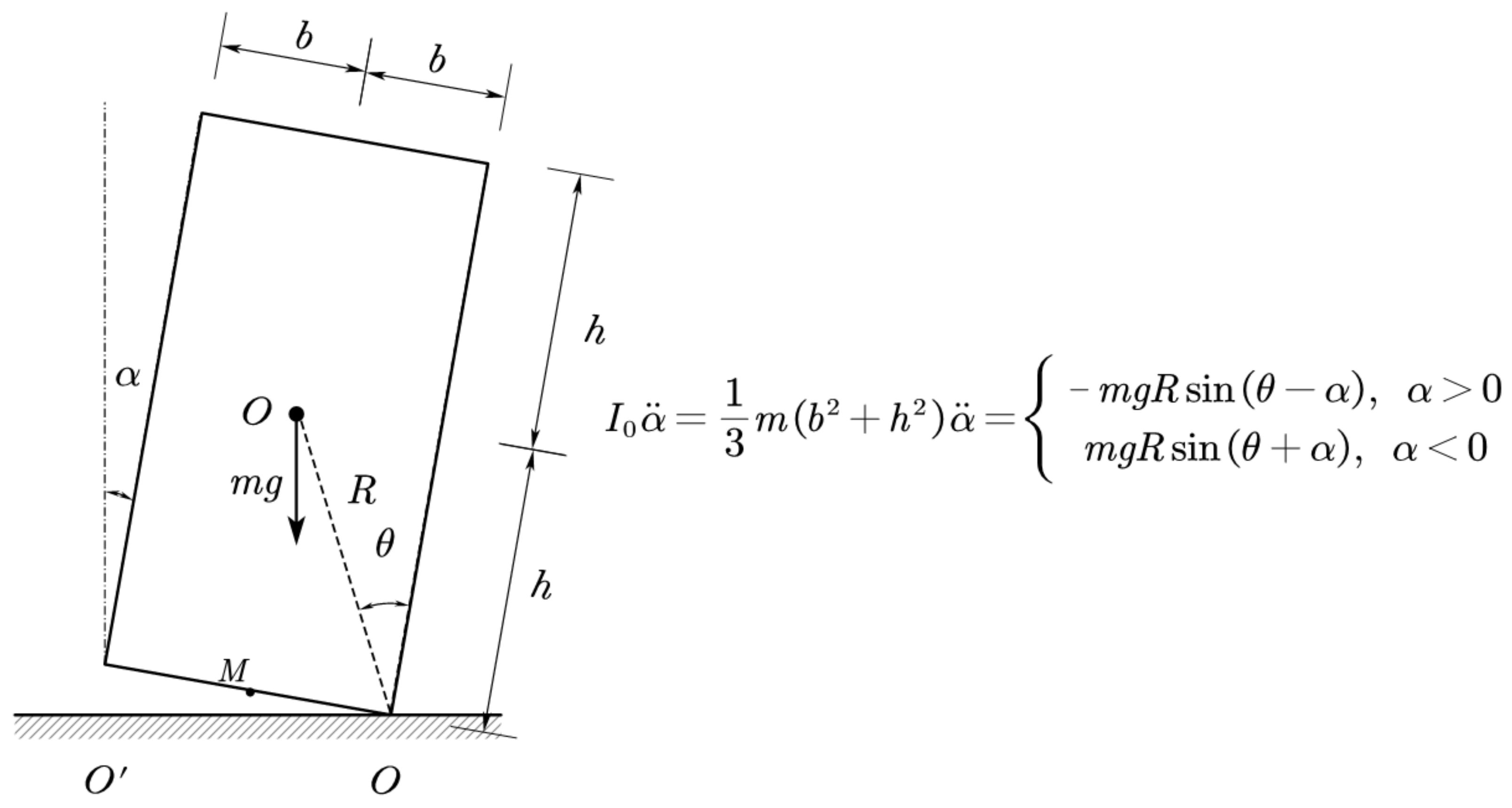
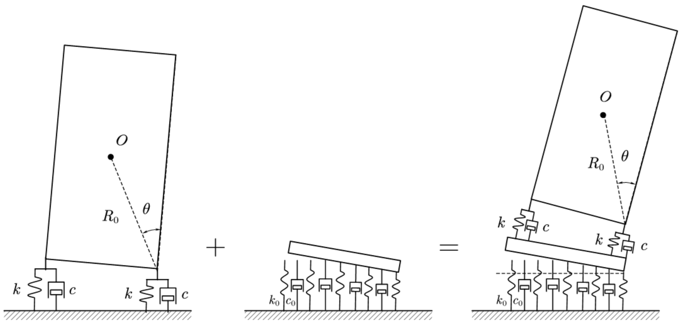
3]. In the Chile earthquake in May 1960, Houser observed that a few elevated water tanks designed with a special construction similar to a hinge joint at the bottom were almost intact after the earthquake, while other reinforced concrete elevated water tanks that seemed more stable were seriously damaged. From this, he proposed a theoretical model of the rigid rocking block (as shown in
Figure 1), started the analysis and research of it, and analyzed the rocking behavior of the rigid rocking block when excited by the base. In 1978, Meek [
4] carried out structural analysis through the simplified single mode model of rocking core tube and found that the rocking core tube can significantly reduce the dynamic response of the structure. The greater the height–width ratio, the more significant the reduction effect of the dynamic response. In 1983, Psycharis and Jennings [
5] conducted a linear analysis of the rocking response of a rigid block on a viscoelastic foundation. In 1985, Yim and Chopra [
6] carried out research on the condition that the bottom of the flexible structure is allowed to lift, and gave the corresponding linear analysis method.
Taniguchi’s research [
7] in 2002 found that a rocking motion is a nonlinear problem, and even simple harmonic excitation can produce many kinds of rocking motion. In 2003, Jeong [
8] conducted research on undamped rocking structures and found that periodic motion and mixed motion are the main dynamic responses of such structures. In 2004, Kuraffia [
9] found that the earthquake damage of structures can be reduced with the structural lifting and rocking motion by studying the rocking structures with post-tensioned tendons. In 2008, Palmeri and Makris [
10] analyzed the nonlinear moment of the momentum equation and found that the main factors affecting the motion of the rocking block were the structural size, structural shape, height–width ratio, stiffness and damping of the foundation, and energy loss in the collision process.
To create a sustainable and well-performing structural form that can rock to release the energy input from the outside, the rationality of its assumptions in design must be fully considered to ensure its long-term stability in practical use. The soil–structure interaction (SSI) has long been a hot topic in earthquake engineering. At present, we usually calculate the dynamic characteristics of the structure based on the assumption of a rigid foundation. Considering the soil–structure interaction, the dynamic characteristics of the structure system will be changed [
11,
12,
13,
14]. In the past, designers usually thought that the interaction effect of soil and structure would make the structure safer and ignored the interaction effect of the soil and structure to develop a more conservative design. However, a large number of studies show that the soil–structure interaction is not always conservative [
15]. In some cases, the SSI effect cannot be ignored [
16,
17,
18].
An actual earthquake disaster shows that the interaction between the soil and the structure may cause the actual natural period of the structure to be larger than the calculated value. Due to the wrong calculation of the structural period, the seismic period of the structure is consistent with the site seismic period in the actual earthquake, resulting in significant amplification of the building response and major damage (the Gediz earthquake in 1970, the Mexico City earthquake in 1985, the Adana Ceyhan earthquake in 1998, etc.) [
19]. George Mylonakis [
20] summarized the disadvantages of the soil–structure interaction with the structure, including increasing the natural vibration period of the structure, increasing the seismic response of the structure, and increasing the ductility demand of the structure.
The research on the analytical solution of the simplified model of the soil–structure dynamic interaction originated from the Boussinesq problem, in which Lamb [
21] used the transformation integral method to study the reaction of an elastic half space surface under a vertical load in 1904. By 1936, Reissner [
22] had analyzed and studied the vibration problem of a rigid circular foundation on the surface of an elastic half space, and integrated the solution given by Lamb, which was considered as the official start of the study of soil–structure dynamic interactions. In the 1950s, many researchers obtained the transient and steady analytical solutions of the translational, rotational, and torsional vibrations of circular and rectangular foundations under stress boundary conditions. By the mid-1960s, Parmelee [
23] had initially revealed the basic law of inertial dynamic interaction. After that, with the continuous improvement of computer performance, the finite element method has been used more often in the research of SSI systems. However, even today, the analytic calculation method still has the advantages of fast calculation and a clear concept. At present, the Winkler foundation model [
24] is the most popular analytical method; additionally, the elastic foundation beam method and the elastic continuum method [
25] are also widely used.
At present, we are not sure if SSI effect will affect the structure with a rocking motion, which also restricts the practical engineering application of rocking structures to a certain extent. For a structure that can rock and relax with a certain degree of constraint, the problem of horizontal sliding hardly occurs, but bottom lifting, settlement, and structural overturning due to overall rotation cannot be ignored. In this paper, based on the simplified analysis model of the rocking block on the rigid ground proposed by Housner and the linear differential equation derived by Psycharis and Jennings, the geometric nonlinear motion equation of the two-spring rigid rocking block model is deduced and analyzed, and the influence of the key parameters on the lifting, rotation, and overturning of the rocking block is analyzed. Then, combined with the Winkler foundation model, the comprehensive response of the rigid rocking block considering the foundation flexibility is studied. The results of the above analysis can provide a reference for the design of structures with a rocking motion.
2. Two-Spring Rocking Block Model
2.1. Model Introduction
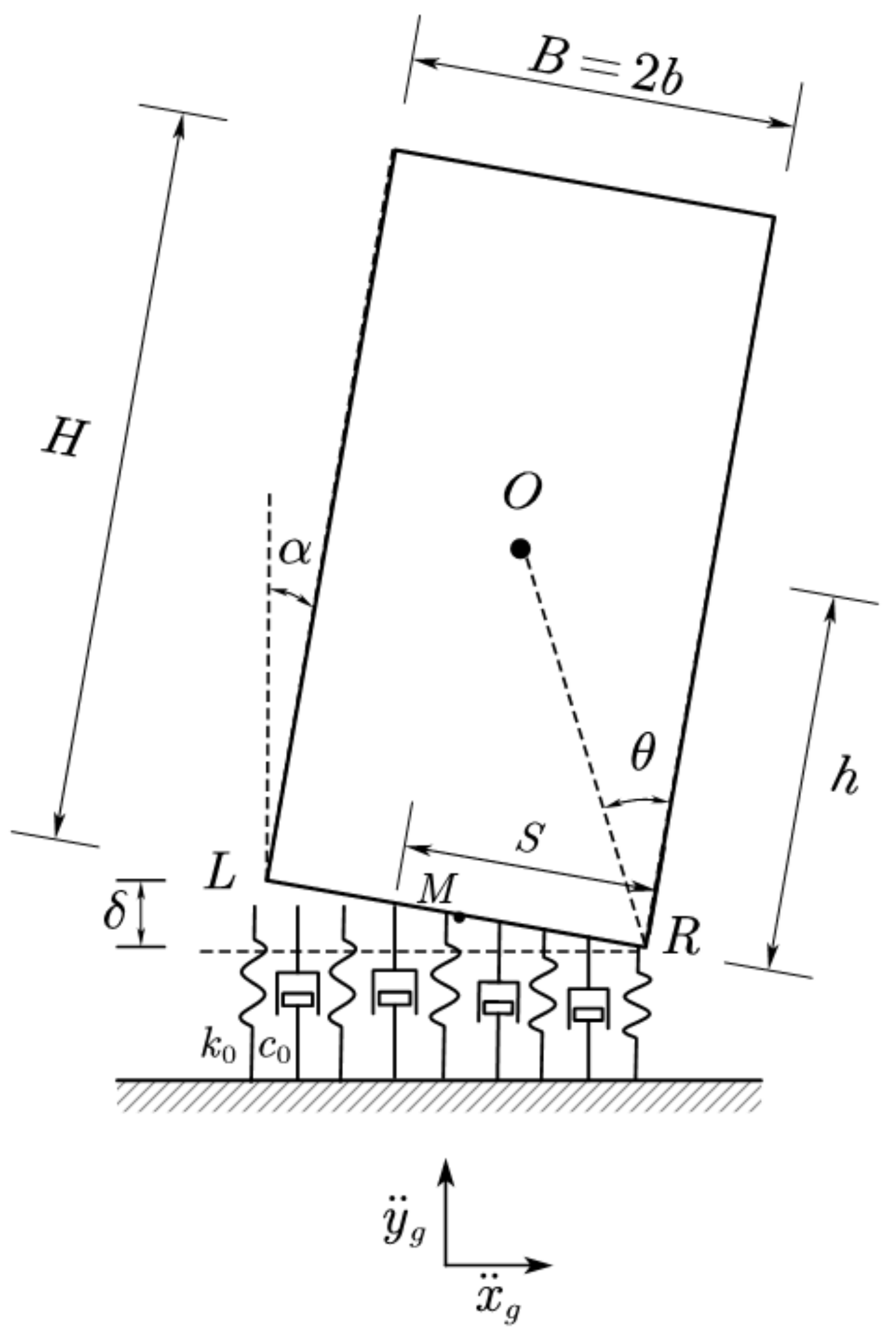
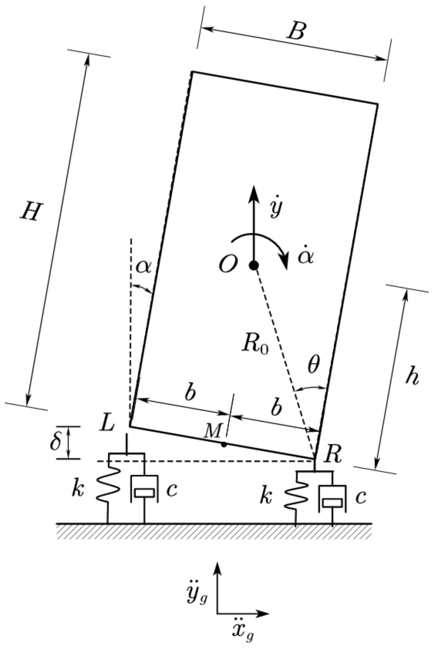
For structures with rocking properties, such as self-centering frames and rocking wall frame structures, they cannot be directly simplified as rocking blocks because the relationship between them and the ground is not a simple contact, but a buffer to avoid direct impact is set at the column bottom or at the bottom of the wall. When we assume that this buffer is elastic and damped, without considering the sliding of the rigid block relative to the base and the fact that the entire base cannot bear the tension, if the displacement of the rigid block moving upward is greater than the displacement due to its own gravity (that is, when the pressure on the spring is zero, the rigid block and the spring are separated), the movement of the uniform rigid block is shown in
Figure 2.
The size of the rigid rocking block is
. It can be seen from theoretical mechanics that when the center of mass of the block rotates beyond the vertical position of the long side, the rigid block will overturn, and the overturning angle
has the relationship seen in Equation (1).
where
,
represent the width and height of the two-dimensional rocking block, respectively;
and
represent half the width
and half the height
, respectively; and
represents the distance from the corners of the rocking block to the geometric center
.
Assume that the rigid block has only two degrees of freedom: vertical and rotation. It can rotate around points L and R, but once it contacts the left or right spring supports, the contact point will only allow vertical movement. When the displacement is small, the rigid block is in continuous contact with the two supports L and R throughout the movement. If the mass of the rigid block is , when the vertical lifting of its side exceeds the displacement of the support spring due to the dead weight of the rigid block , separation occurs and the block is supported only on the other side. Therefore, a rigid block has four motion states:
Complete contact at the L point and R point;
Only contacts the L point;
Only contacts the R point (corresponding to the motion state in
Figure 2);
The rigid block is separated from the two points and moves freely.
Since the rigid block will not be constrained after it is separated from both supports, it will be in a completely free motion state, so this situation should be avoided. Therefore, the first three motion states are mainly studied here.
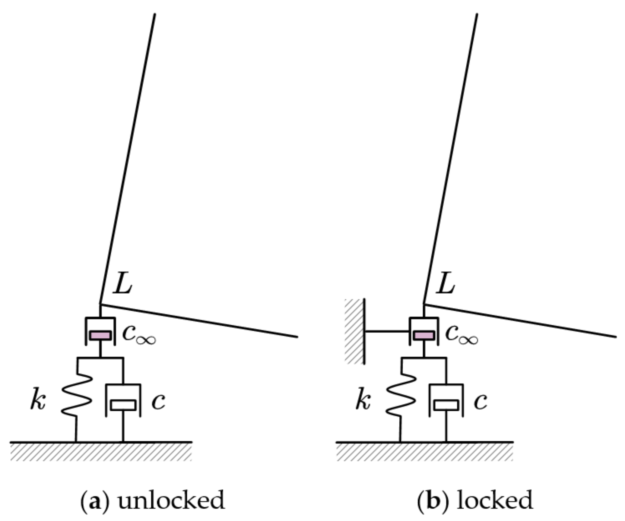
In Housner’s model, energy dissipates when the rigid block contacts and collides with the rigid foundation, which will reduce the amplitude of each shaking until it finally stops. However, after the introduction of elastic bearings, energy dissipation will not occur automatically, and an energy dissipation mechanism must be introduced manually. Therefore, a new damper is introduced [
5], whose damping constant
. Tt is connected in a series at the top of spring
and damper
. Because of its large damping coefficient, the damper is essentially equivalent to a rigid link, which does not affect the response of the system, except in the case of collision. At the moment of impact, we assume that the rigid damper is locked, as shown in
Figure 3b, for a short period of time
, the damper is moved
, then the rigid damper unlocks. During this period, the spring
and damper
are not activated, and the response is only affected by the rigid damper. Due to the effect of this damper, the velocity of point L is reduced. After
, the impact buffer is unlocked, which has no impact on the response of the system thereafter.
Assume that
and
is a constant and the preset collision energy dissipation mechanism has a significant impact on the speed, but not on the displacement; then the calculation of the velocity relationship and energy loss is as seen in Equations (2) and (3).
where
,
,
,
correspond to the vertical speed and rotation angular speed before and after the collision, b is half of the width of the rigid block, and
,
correspond to the inertia moments of the rigid block around point O and point M, respectively. According to Psycharis and Jenning’s research,
1,
is a parameter related to the physical characteristics of the rocking block itself and it can be calculated as Equation (4).
where
, denoting the shape factor of the rigid block. For a rectangular block (
), Equation (4) is then simplified to
. Therefore, there is a limit overturning angle
, as Equation (5).
When the rigid block is too short and wide, , , the rocking will not occur after collision, therefore the rocking block cannot be set too short.
In most practical cases, only a rocking motion occurs and neither support is separated from the frame, and the value of the coefficient of restitution
is close to
. Therefore, the rocking response is only related to the overturning angle
and the frequency
of the rigid block itself. The frequency
can be calculated as Equation (6).
The spring support is assumed to be a viscoelastic Kelvin–Voigt model, that is, the spring stiffness and the damping coefficient of the viscous damper are defined as Equation (7).
The vertical frequency coefficient
and damping coefficient
both depend on the vertical stiffness of the supported elastic cushion. To facilitate the analysis, the scale factor is defined as Equation (8).
2.2. Motion Equation of Full Contact
When both ends of the rigid block are in contact with the spring, the force analysis is as shown in
Figure 4.
The corresponding motion equation is shown in Equation (9).
and are the horizontal and vertical accelerations of the center of the rigid block, respectively; and are the vertical reactions of the left and right bearings, respectively; and are the horizontal reaction force of the left and right supports, respectively; and are the time history of horizontal component and vertical component of ground acceleration, respectively; is the acceleration of gravity; and the other characters have the same meanings as above.
Assume that the vertical component of the bearing
(
) is
, and the upward displacement and velocity are
and
. The stress relationship is shown in Equation (10).
As the rigid block is in a full-contact state, both ends of the support shall meet the requirements . Since the bearing is assumed to be free from any tension, the first bearing will be separated from the rigid block when and .
Under the assumption above, the rigid block is not allowed to slide, so in fact, the whole system has only two degrees of freedom. For convenience, the vertical displacement
and rotation angle
of the center of the rigid block are selected. In addition, in the full-contact state, the displacement of a point on the rigid block is actually the superposition of the vertical displacement and the rotation displacement around the bottom center point M. According to the motion theorem of the center of mass, the expression of the displacement at the center of mass can be deduced as Equation (11).
Combined with Equations (7)–(11), the second-order nonlinear differential equation of a rigid block in full-contact motion is finally obtained as Equation (12).
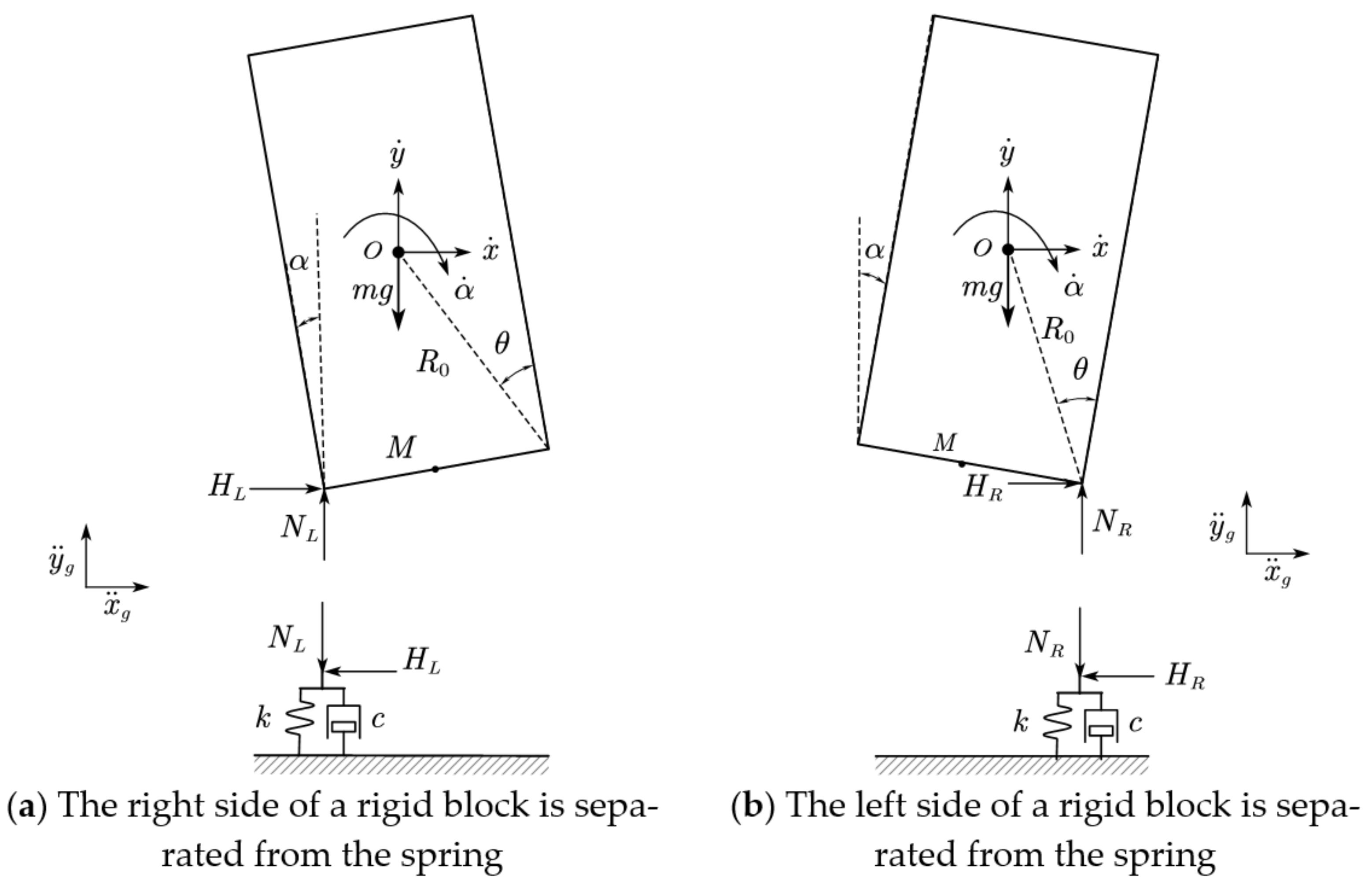
2.3. Motion Equation of a Rigid Body with One Side Detached
As described in
Section 2.2, when the upward displacement of the rigid block is greater than its sinking
due to its own weight and upward velocity
, the left side will be separated from the support, and only the right side will bear the force, as shown in
Figure 5b. At this time, the dynamic equation can be obtained according to the force balance conditions shown in Equation (13).
The corresponding displacement relation is shown in Equation (14).
Combining Equations (7), (8), (10), (13), and (14), the equation of motion after the left end separation is obtained. Through a similar process, the equation when the right end is separated can be obtained. By combining the two, the equation expression when only one side is stressed can be obtained as Equation (15).
The opposite signs in the equation denote that the rocking block rotates left or right.
2.4. Parameter Analysis
According to geometric analysis, the maximum rotation angle interval where the rigid block never separates during movement is
, and the
can be calculated as Equation (16).
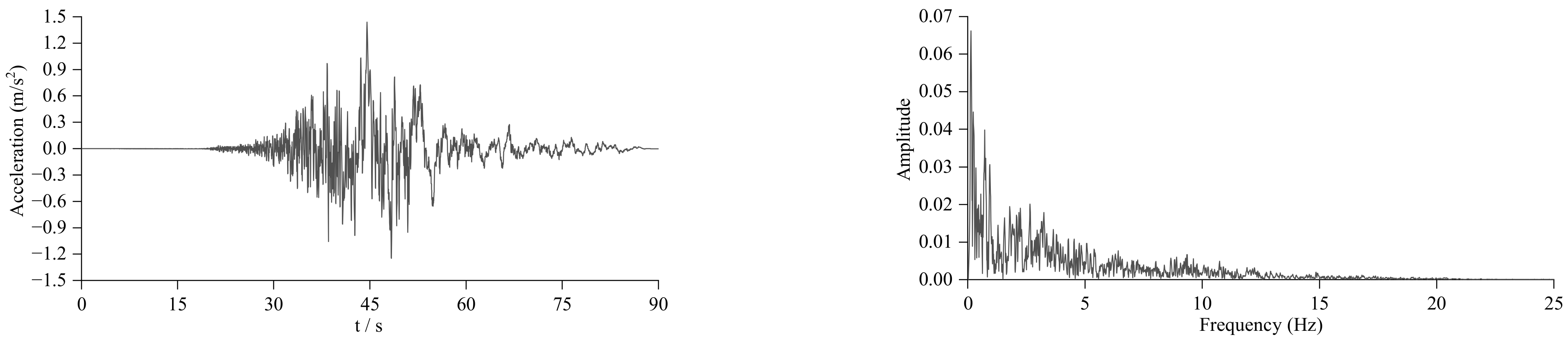
The suffered unit excitation in the x-direction of the model is shown in Equation (17) and
Figure 6.
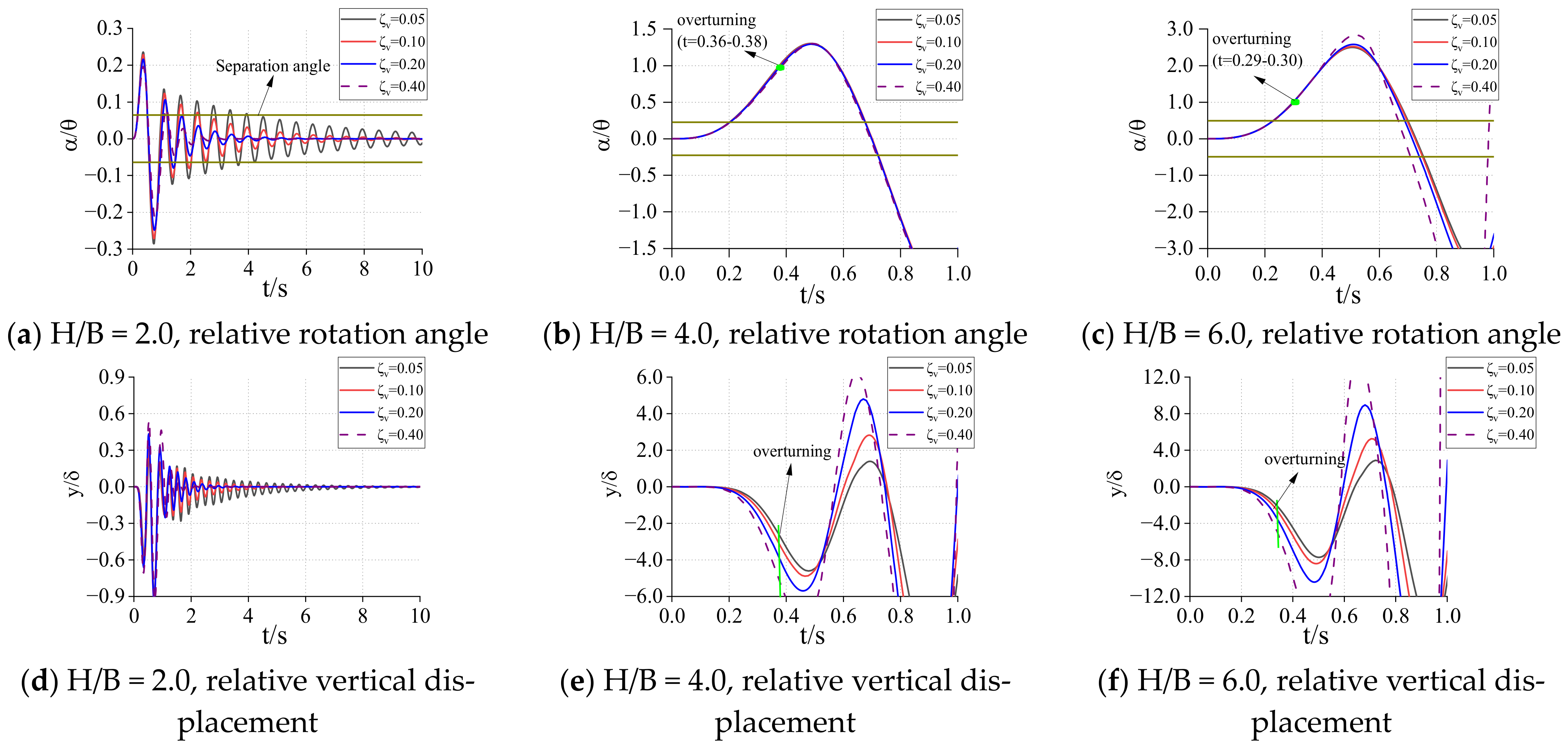
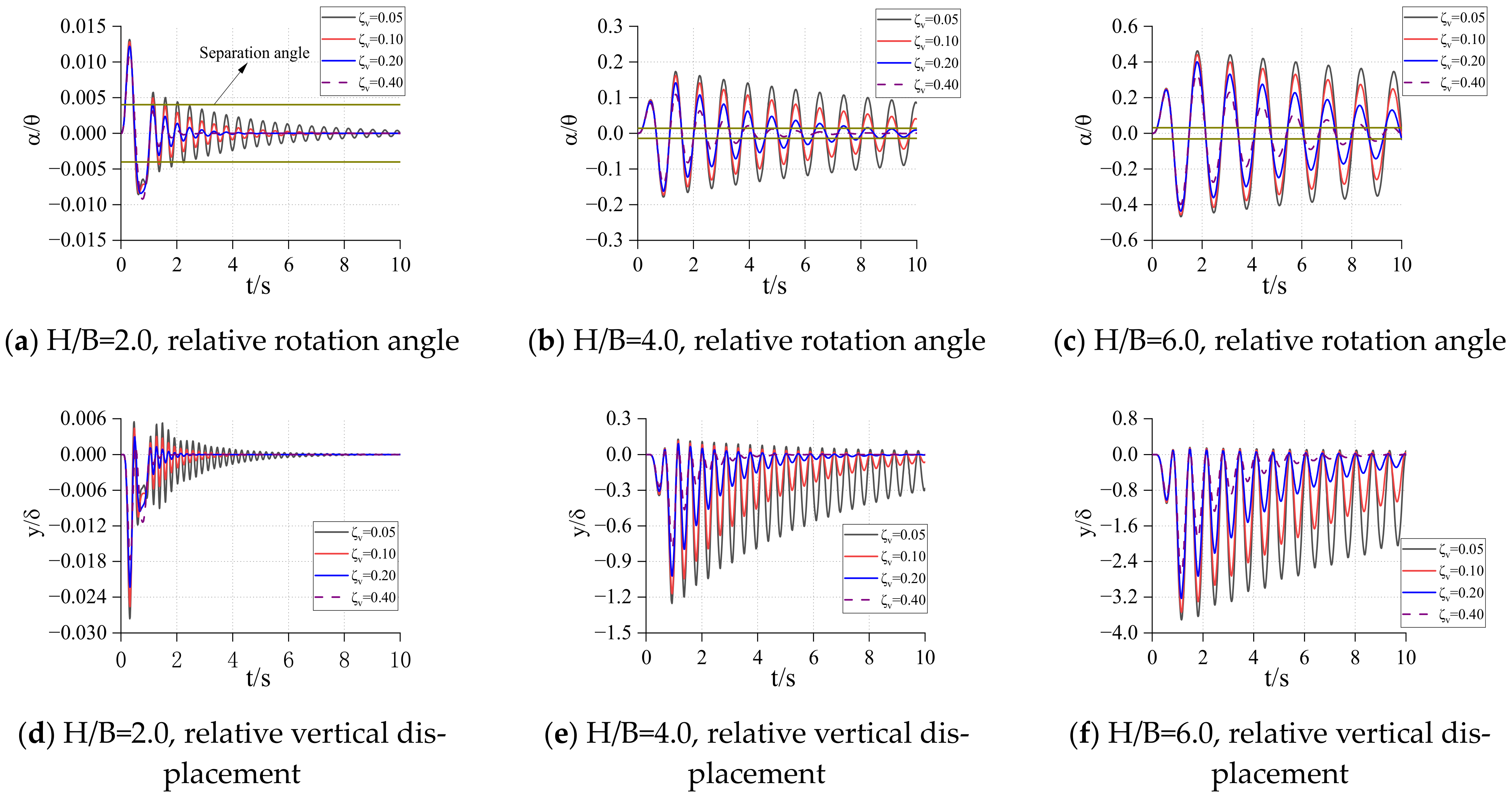
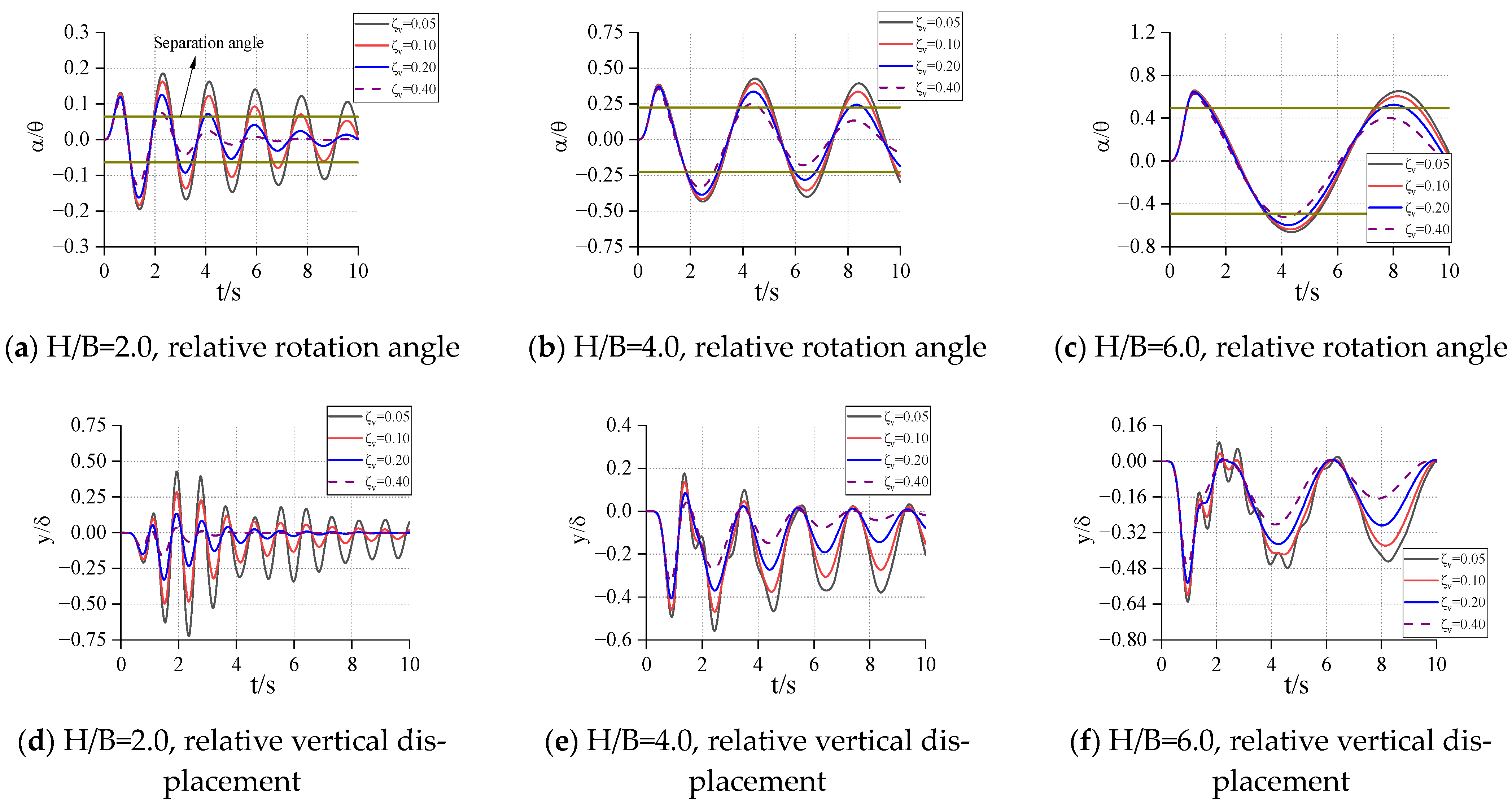
Suppose that the kinetic energy recovery coefficient of the rigid rocking block is always , the effects of different height width ratios (), different sizes (), different spring stiffness (), and different damping () on the response of the rigid block are analyzed. In order to facilitate the analysis, the clockwise rotation angle and vertical displacement of the two parameters of the response are normalized and divided by the overturning angle of the rigid block itself and the displacement generated under the self-weight condition, respectively.
The response of the structure within 10s is solved by numerical integration programmed in Matlab, and the response results are shown in
Figure 7,
Figure 8,
Figure 9,
Figure 10,
Figure 11,
Figure 12,
Figure 13,
Figure 14 and
Figure 15. In order to indicate the separation of one end of the rigid block from the spring, the rotation angle
when one side of the rigid block is separated is marked in the figure (two brown horizontal solid lines). In
Figure 7,
Figure 8,
Figure 9,
Figure 10,
Figure 11,
Figure 12,
Figure 13,
Figure 14 and
Figure 15,
indicates the lifting of one side of the rigid rocking block,
indicates that the rigid block rotates counterclockwise and inclines to the left,
means that the rotation angle has exceeded the overturning angle of the rigid block itself, and the subsequent response becomes meaningless, so the overturning time occurs at the mark in
Figure 7,
Figure 8,
Figure 9,
Figure 10,
Figure 11,
Figure 12,
Figure 13,
Figure 14 and
Figure 15.
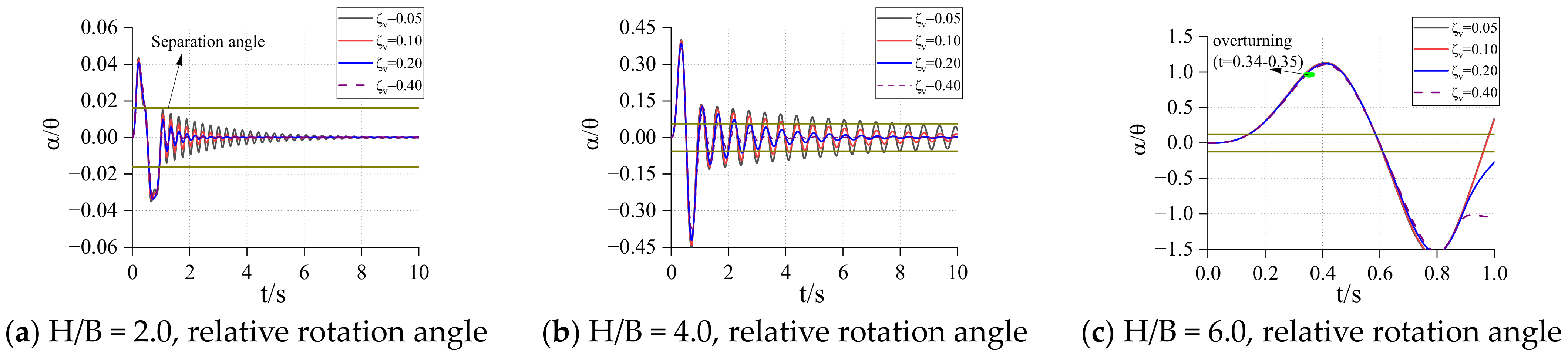
In
Figure 7,
Figure 8,
Figure 9,
Figure 10,
Figure 11,
Figure 12,
Figure 13,
Figure 14 and
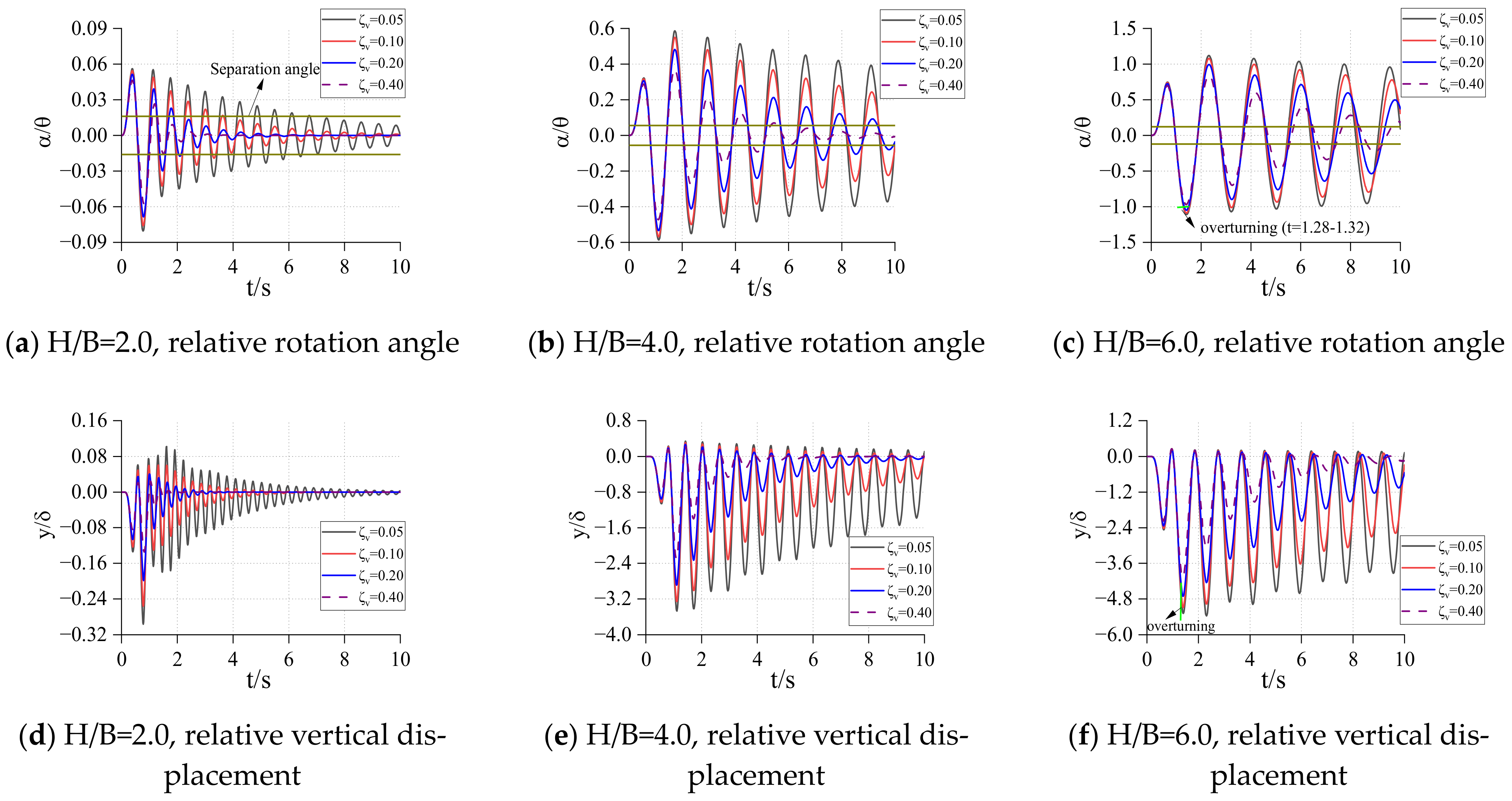
Figure 15, each figure is the response of the structure with different height–width ratios under a fixed rigid block size and spring stiffness. It can be found from these figures that when the size of the rigid block and the stiffness coefficient of the bottom spring are determined, its relative rotation response and relative vertical displacement response increase with the increase of the height–width ratio of the rigid block. When the size of the rigid block is big and the stiffness coefficient of the spring are small, the rigid block may overturn in a very short time under excitation. With the increase of the height–width ratio, the overturning time will be shorter and shorter, and the occurrence of this overturn does not change with the different damping of the structure. When the spring stiffness at the bottom of the structure is large, the overturning response may occur after the end of excitation (
in
Figure 11).
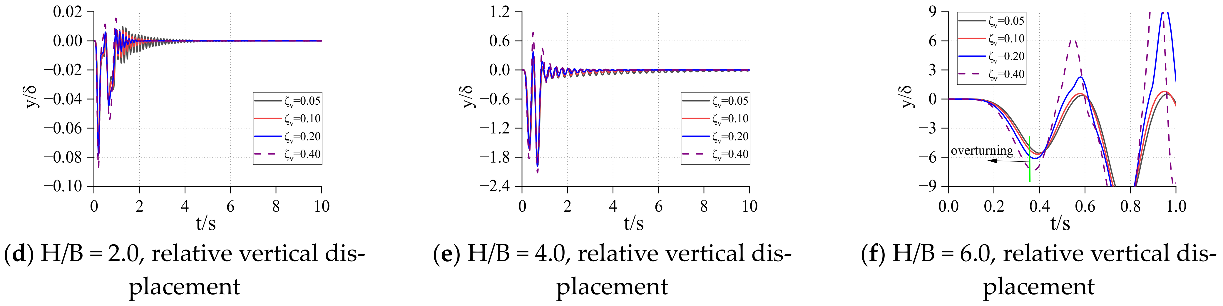
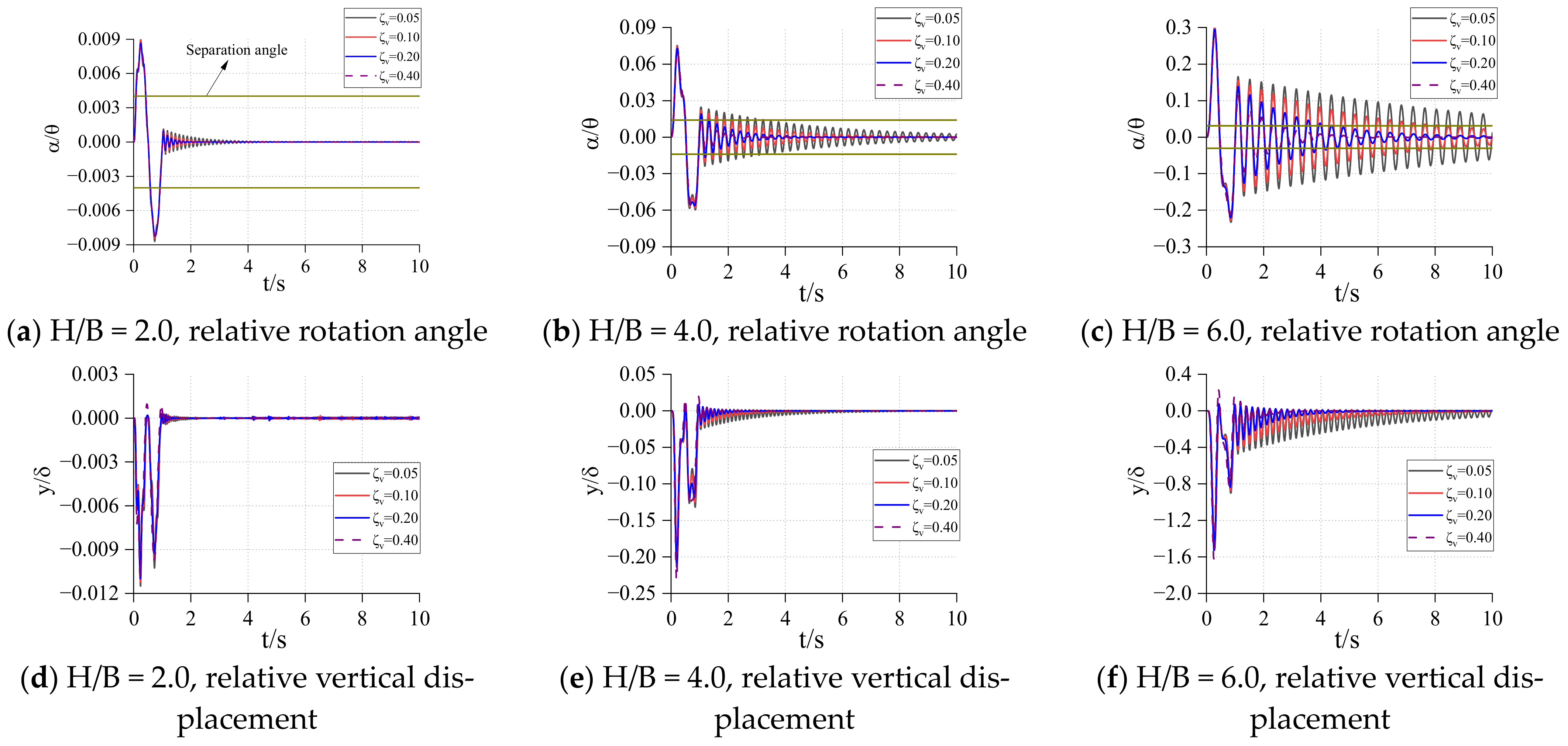
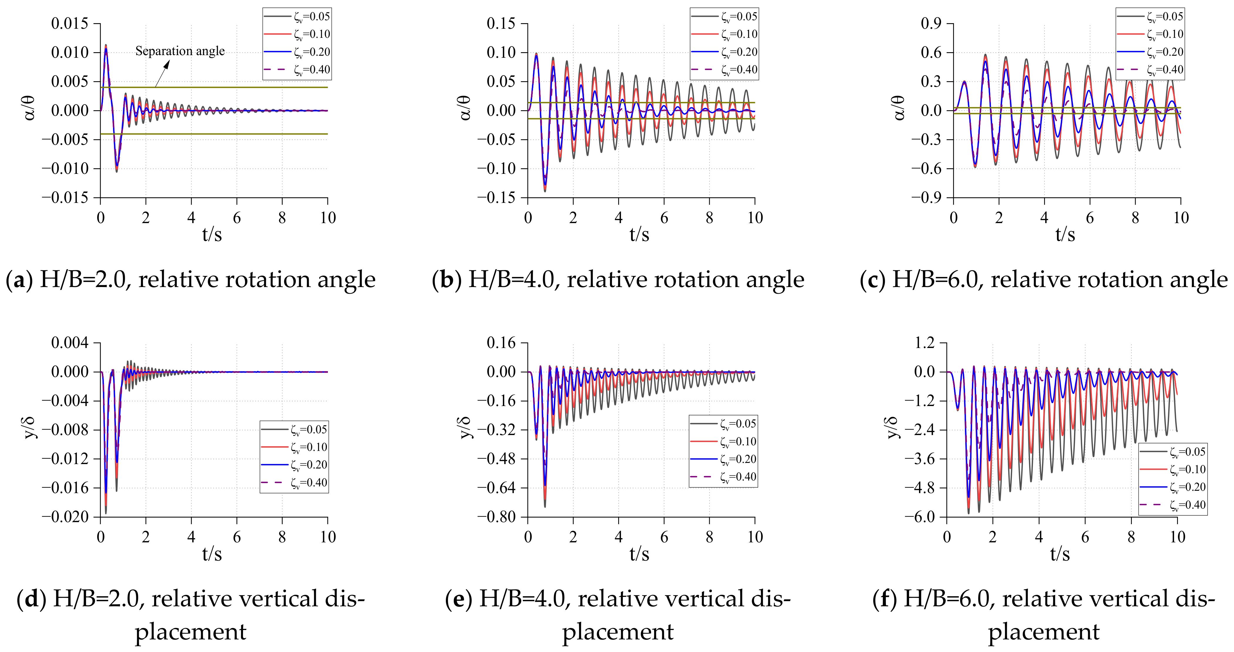
From the comparison between the figures, when the height–width ratio of the rigid block and the stiffness coefficient of the spring are determined, it takes longer for the structure to become stable under the damping effect, as the size of the structure increases. When the height–width ratio is small, the response of the relative rotation angle and vertical displacement of the rigid block decrease with the increase of the size of the rigid block. When the height–width ratio is large, the response of the structure increases first, and then decreases as the size of the structure increases. This shows that for a structure with a larger height–width ratio, increasing the structure size may increase the response. In general, as the size of the structure increases, the possibility of overturning decreases and the occurrence time becomes later.
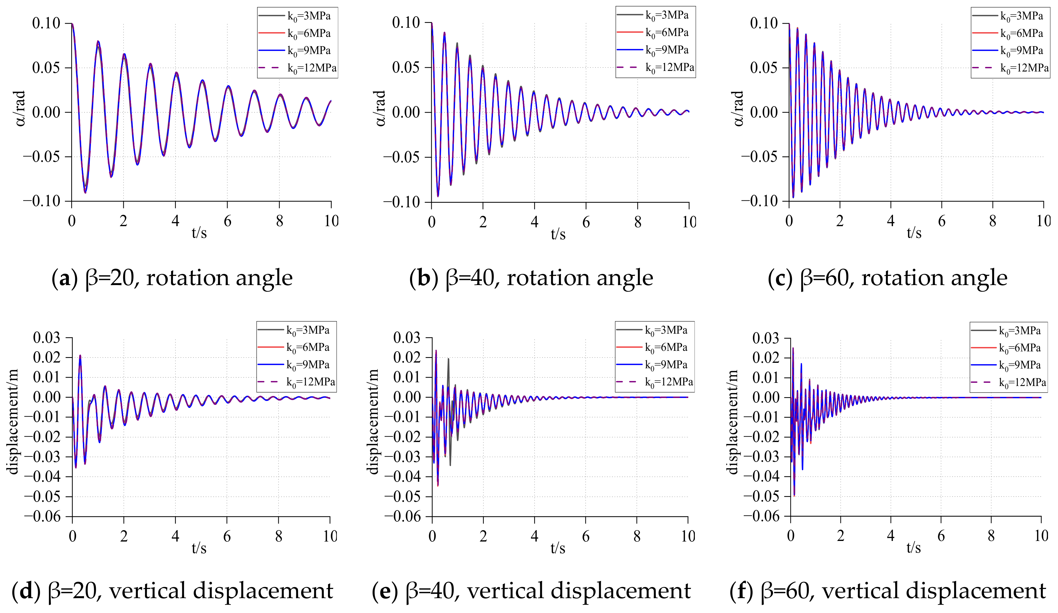
When the height–width ratio and size of the rigid block are determined, with the increase of the stiffness of the spring, the relative angular response and displacement response of the rigid block decrease. If the structure will overturn, the time point of overturning will be delayed. However, the subsequent response of the rigid block will gradually increase, or even exceed the initial response. At this time, the damping can well reduce the subsequent response amplitude of the rigid block. When the damping is large, the rigid block can be stabilized in a very short time.
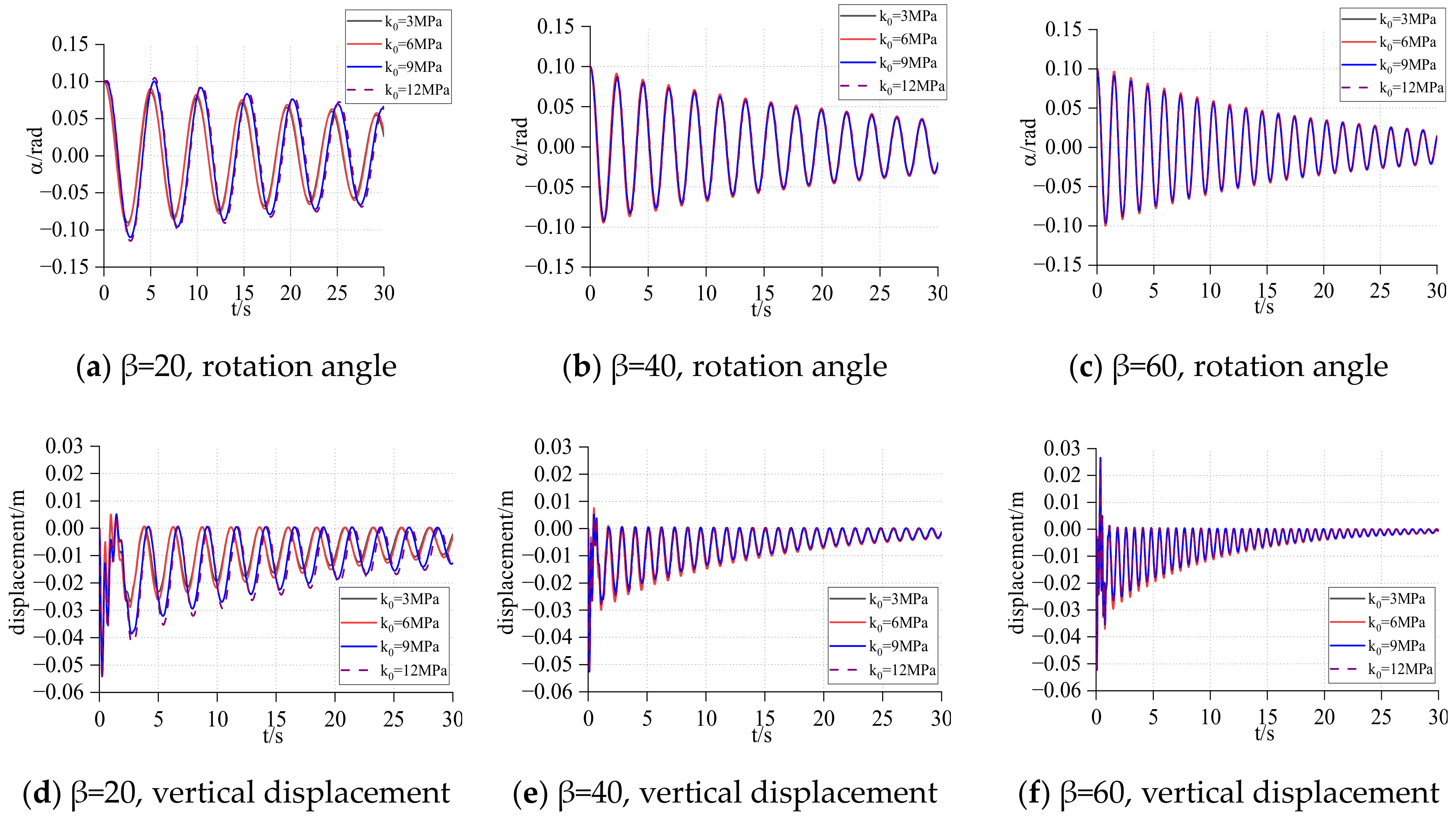
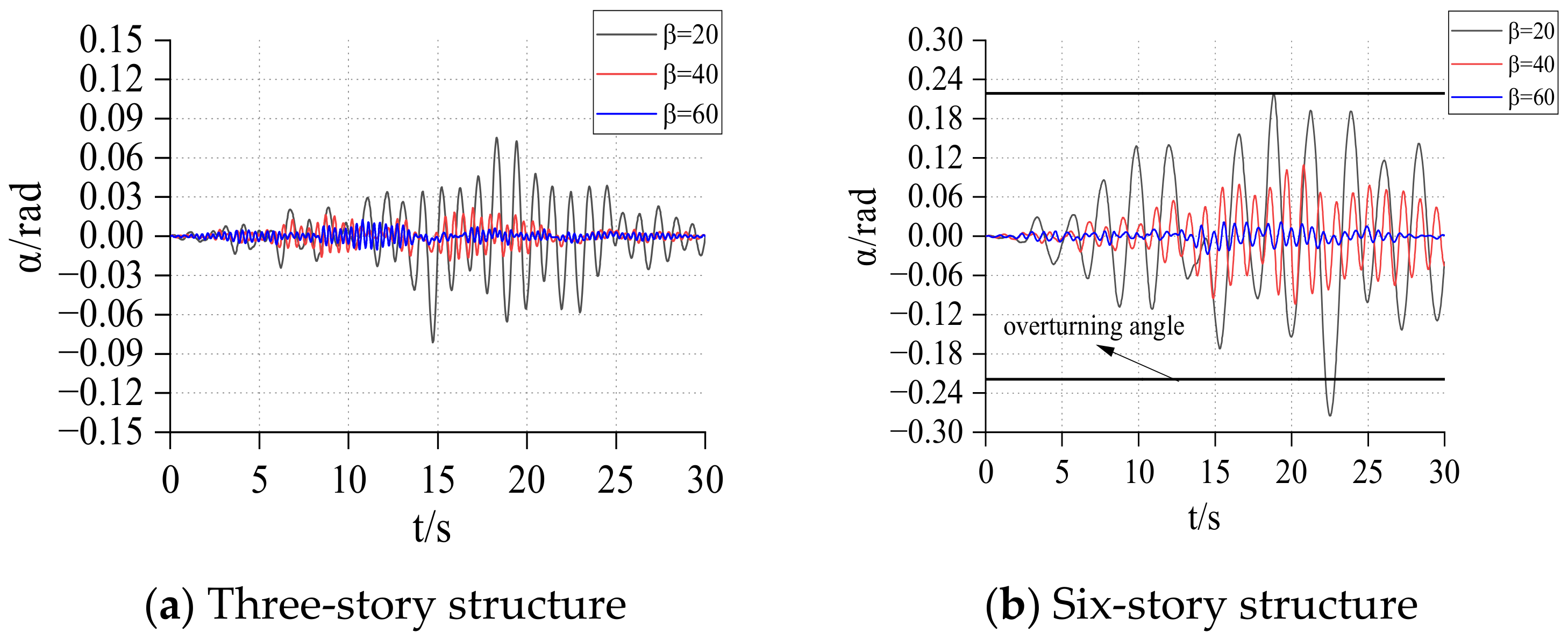
3. Winkler Foundation Model
In order to consider the flexibility of the foundation under the rigid rocking block, the two-dimensional model of the Winkler foundation was used to simulate the foundation soil. The parameters of the Winkler foundation model are essentially the same as those of the two-spring models. The difference is that the bottom is replaced with a uniformly distributed damper and a spring in parallel. The stiffness and damping of each spring are
and
, respectively. The displacement generated under the dead weight of the rigid block is
. The model diagram is shown in
Figure 16.
Assuming that the displacement and rotation angle are relatively small, the motion equation under a full-contact state is shown in Equation (18).
where
, denoting the moment of inertia of the rigid block to the bottom midpoint M. When the left end is raised, the motion equation is shown in Equation (19).
where
It can be seen from the equation above that the equations of motion of the system are uncoupled during the full contact process, and they can be solved directly. When one side of the rigid block is separated, the equations are coupled and highly nonlinear due to geometric complexity. The contact length with the bottom foundation changes with and , which makes the problem more complicated.


