Abstract
The friction performance and compression properties of geotextile bags under different degrees of consolidation are researched through the slope sliding test, direct shear test, and unconfined compression test in this study. The geotextile bags are made up of geotextile and tailings sands obtained from a construction site of a prototype tailings dam in Yunnan Province. The slope sliding test is considered as an easy method to study the friction performance of geotextile bags with different degrees of consolidation. Through the test, the friction coefficients between the bags were obtained. Given the geotextile bags can withstand the vertical load in practical engineering, the direct shear test is also proposed and conducted. The ultimate bearing capacity of the geotextile bags with different consolidation degrees is studied in the unconfined compression test. The test reveals that the ultimate bearing capacity of geotextile bags, although featured with different moisture contents before the test, stays the same under the condition of slow loading. Finally, a stability analysis method based on the limit equilibrium theory is developed to simulate the stability of the tailings dam using geotextile bags (TDGB). According to the test results, the TDGB has demonstrated an improved stability compared with the general tailings dam.
1. Introduction
With the fast development of the mining industry, tailings as the waste following ore smelting have also increased sharply [1]. In the year 2020 alone, the estimated phosphate ores unearthed worldwide were as high as 290 Mt, with 30–40% of the phosphate ore mass discarded as tailings [2]. In 2019, the tailings emissions reached nearly 1.2 billion tons in China alone [3]. The primary disposal method of tailings is the deposit on the surface of the earth to form tailings dams [4]. More than 12,700 tailings dams of various types in service have been constructed in China by the end of 2019 [3]. In addition, nearly 44% of the tailings dams in some industries are exposed to dangerous and extended service [5]. About as high as 95% of tailings dams adopted the upstream tailings dam construction method, which involves discharging the tailings from the top of the dam naturally to form a dry beach surface, taking advantage of the gravity field [6]. As a special industrial construction, the tailings dam often causes serious disasters due to various reasons [7], such as seismic liquefaction, slope instability, amounts of rain, and overtopping [8]. In China, the failures of tailings impoundments have resulted in the loss of many lives and considerable property damage, including irreversible pollution in downstream areas [9]. For instance, on 10th August of the year 2008, a failure occurred in an iron ore tailings impoundment located in Shanxi province, northwest China, resulting in a total of 277 deaths [10]. The major failures of tailings ponds that have occurred in China since 1962 are summarized in Table 1 [11].

Table 1.
Major failures of tailings dams in China.
With continuous improvements in beneficiation technology and recovery rates, tailings have become less coarse, with fewer particles larger than 0.074 mm and more fine particles smaller than 0.03 mm [12]. Fine-grained tailings are featured with poor water permeability after storage, long consolidation time, low mechanical strength, and the incapability of dissipating excess pore water pressure [13]. However, a large number of coarse particles are often required to construct tailings embankments in the upstream method [14]. If the traditional upstream storage method is used for fine-grained tailings, some common problems [15] such as dam construction difficulty, poor drainage of the dam body, the slow slope of the sedimentary beach, and poor stability are often encountered [16]. Therefore, improving the stability of the tailings dam poses a challenge to mine operators [17]. Ye et al. [18], Zhang and Wang [19], and Xue [20] studied the application of the geofabriform method damming technology in tailings dams and suggested that geotextile bags in the tailings dams’ construction were an effective remedy for all these problems. The application of geotextile bags in the construction of tailings dams enhances the stability of the dam. The successful experiences in the designing and construction of conventional water storage dams avail the economical and safe construction of tailings dams. In Figure 1, a zoomed-in partial view of a prototype tailings dam constructed with geotextile bags is demonstrated in Yunnan province of China, while in Figure 2, a schematic of a cross-section of such a tailings dam is shown.
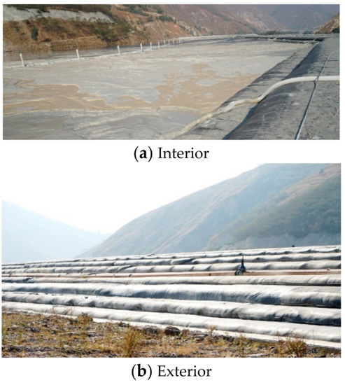
Figure 1.
Zoomed-in partial view of the tailings dam constructed with geotextile bags in Yunnan province: (a) interior; (b) exterior.
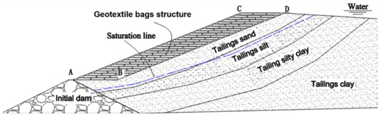
Figure 2.
Schematic of the cross-section of the tailings dam constructed with geotextile bags.
Construction with geotextile bags usually involves arranging two large bags made of geotextile materials in a row, filled with liquid concrete, cement mortar, or sand via pumps, which tend to form into a whole body of strength with a high level of water permeability. This method is also known as the protection of bank slope stability construction technology of slurry [21]. Geotextile bags, as a type of building material, are widely used in embankment projects [22,23,24], which can prevent water erosion on the dam and bank slope [25]. In addition, the geotextile bag has a multitude of applications in foundation treatment [26,27]. The theoretical study of the geotextile bags is promoted with wide applications in practical engineering [28]. Currently, research on the geotextile bags focuses mainly on the material properties of the bags. Bai Fuqing and Liu Sihong et al. [29] analyzed the strengthening principle of the geotextile bags using the three-dimensional stress state. The expression of ultimate compressive strength was deduced under the three-dimensional stress state by using the generalized Mises failure criterion and the failure criterion of Lade–Duncan. Qiu Changlin and Yan shuwang [30] present the formulation of a geotextile bag and develop a numerical analysis method to study the mechanical behavior of large-scale geotextile bags, which is further validated in a case study. According to the study conducted by Qiu Changlin and Yan Shuwang, the tension of the large-scale bag is significantly higher than that of a small bag at the same pumping pressure. Therefore, the large-scale geotextile bag should be kept at low pumping pressures to satisfy the strength requirement. At low pumping pressures, the cross-section of the geotextile bag is flat, featured with a higher horizontal length than the vertical one, which is different from the circular tube of a small-scale geotextile bag. Miao Wang [31] studied the mechanical properties of the geotextile bags by model tests, theoretical derivation, and numerical simulation, providing some guidance for the design and application of the actual geotextile bags. T. N. Lohani et al. [32] evaluated the compressive strength and the shear strength of a soil bag pile under vertical compression and lateral shear compression, respectively, by performing a series of full-scale loading tests. The effects of soil bag material, backfill soil type, number of soil bags in a pile, and associated effects of end restraint at the top and bottom ends of a soil bag pile were evaluated. Sihong Liu et al. [33] introduced the reinforcement principle and some properties of soil bags. Some practical application cases of soil bags are presented in Japan, such as the reinforcement of building and road foundations and the construction of retaining walls and debris-diversion embankments. The reinforcement of soil bags is contributed by a tensile force, which thereafter tends to induce an apparent cohesion. Tensile force is produced as a result of the extension of the perimeter of the soil bag under the application of external force. Wang Yan Qiao, Liu Sihong, et al. [34] conducted a series of model tests on the sandy soil slopes with and without reinforcement of the soil bags. The reinforcement effect of the soil bag is validated by comparing the slope failure modes and the ultimate bearing capacities. Liu Sihong and Bai Fuqing et al. [35] proposed a method for an expansive soil channel slope with soil bags and introduced the mechanism of the proposed treatment method. A number of the swell potential, swelling pressure, seepage, and interlayer friction tests were conducted on soil bags filled with expansive soils, which were taken from a construction site of the South-to-North Water Transfer Project in China. K. Matsushima. et al. [36] performed a series of lateral shear loading tests on a pile of three full-scale soil bags stacked horizontally with inclinations at different vertical confining pressures to study the shear strength and deformation characteristics of geosynthetic soil bags. C.-C. Huang.et al. [37] developed a limit-equilibrium-based stability analysis method to simulate the stability of unreinforced sand slopes and geosynthetic-reinforced sand slopes that had been stabilized with soil bags stacked on the slope face. The stability of unreinforced and reinforced sand slopes when loaded with a rigid strip footing placed on the slope crest was evaluated by performing the physical model tests. The stabilizing effects of an inclined stacked soil bag facing with extended reinforcement strips were confirmed.
The successful applications of geotextile bags in the tailings dam solve the problem of the difficult damming of fine-grained tailings and improve the stability compared with the conventional damming method. However, the mechanism for improving the stability of the dam body is not clear. It is urgent to do some research to provide theoretical support for the engineering application of the tailings dam with geotextile bags. In this paper, the friction performance and compression properties of the geotextile bags with different degrees of consolidation were studied through the slope sliding tests, direct shear tests, and unconfined compression tests. In the traditional tailings dam stability calculation, the Swedish slice method and the simplified Bishop slice method are recommended by the specification. Still, using the methods to analyze the stability of the tailing dam with geotextiles is not reasonable. Therefore, based on the failure characteristics of the tailings dam with geotextiles, an innovative stability analysis method based on the simplified Bishop theory is proposed.
2. Experiments
2.1. The Slope Slip Test of the Geotextile Bag
To study the friction properties and obtain the friction coefficient among geotextile bags with different moisture content, the slope slip test of the geotextile bag is conducted by aiming to provide some necessary parameters to the stability calculation of the tailings dam. Six geotextile bags in the dimensions of 0.5 m (length) × 0.5 m (width) × 0.1 m (height) are divided into three groups and consolidated outdoors for 4 days, 8 days, and 12 days, respectively. For the convenience of the laboratory conducting the experiment, a ramp device is designed and fabricated, as shown in Figure 3. The sloping plate is designed with a dimension of 1.5 m × 1.5 m, with a slope angle that can be adjusted in the range of 0–60°, indicated by the dial. Firstly, two geotextile bags with the same consolidation days were neatly stacked on the test device, where the lower bag was fixed by a baffle to prevent falling along the slope. The dial was turned slowly with the increasing slope inclination. The dial was stopped when a relative sliding occurred between two layers of bags. The reading obtained from the dial is the critical angle of the two-layer bags sliding relatively.
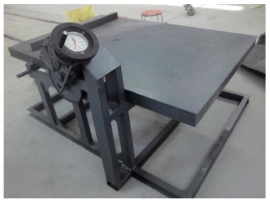
Figure 3.
The device of the slope sliding experiment.
Lastly, the friction coefficient between the bags is calculated following Equation (1) below.
where is the friction coefficient, and refers to the critical angle.
Each group was tested repeatedly four times. After the tests, the moisture contents were measured by sampling the sand from the bag. The test results and the corresponding moisture content are shown in Table 2.
Table 2.
The test result and the corresponding moisture content.
The test results indicate that a longer day of consolidation and a lower water content tends to lead to a greater friction coefficient between the bags. The friction coefficient between the geotextile bags after 8 days of consolidation is approximately 0.53, which is converted into an internal friction angle of 28°, which provides theoretical guidance for the design and construction process of the tailing dam. To use the skidresistance between the bags as far as possible without delaying the construction, the time of laying the upper layer should be controlled reasonably after laying the lower layer.
2.2. The Shear Tests of the Geotextile Bags
To study the friction properties between the bags under the vertical load, the shear performance test is designed and performed with the test device shown in Figure 4. The principle of the shear tests of the geotextile bags is the same as that introduced in Soil Mechanics [38]. The dimensions of the upper and lower pressure plates are 0.8 m × 0.8 m ×0.1 m (length × width × height) to provide sufficient rigidity. Four bags in the dimension of 0.5 m × 0.5 m × 0.1 m (length × width × height) which were consolidated outdoors for eight days were used. The vertical load and horizontal load were applied by hydraulic jacks, and horizontal displacements were measured by the dial indicator. Referring to the concrete block compression test method, considering the strength and flexibility of the geotextile bag, the loading control method is adopted, and the loading rate is 2 kN/s. The applied vertical loads are 50 kN, 80 kN, 100 kN, 130 kN, 180 kN, 220 kN, 250 kN, and 280 kN, respectively.
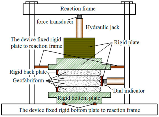
Figure 4.
The device of the direct shear experiment.
During the test, four geotextile bags were stacked together, and then a vertical load was applied on the upper part of the geotextile bag. Once the load is stable, a horizontal load was applied on the sides of the second and third geotextile bags. When the horizontal displacement of the geotextile bags suddenly increases a lot, it is considered to be damaged, and the shear stress and horizontal displacement at the time of failure are measured. According to Coulomb’s law, the internal friction angle and cohesion between the geotextile bags can be obtained. According to the test results, the relation curves between shear stress and shear displacement were obtained as shown in Figure 5.
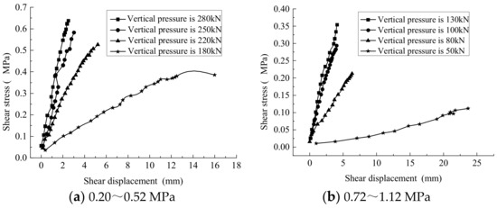
Figure 5.
Shear stress and shear displacement curve under different pressures.
To obtain the friction coefficient, the relation between the pressure stress and the ultimate shear strength was developed and shown in Figure 6. The slope of the curve indicates the friction coefficient between the bags.
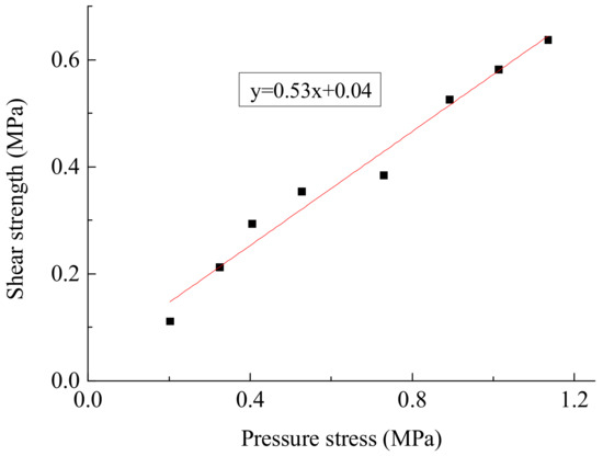
Figure 6.
The curve of shear strength and pressure stress.
According to Figure 5, at the ultimate shear strength between geotextile bags, a higher vertical pressure leads to a smaller lateral deformation. Many factors contribute to such a trend. For one, when the vertical pressure is small, the sand in the geotextile bag is not fully consolidated and relatively loose, resulting in a low stiffness of the geotextile bag and a higher tendency to deform. With the continuous increase in9 vertical pressure, the water in the geotextile bag is gradually discharged, resulting in more compacted tailings in the bag. At this point, the stiffness of the geotextile bag is improved, with a lower tendency to deform.
As shown in Figure 6, the friction coefficient between the geotextile bags after 8 days of consolidation obtained from the shear test is approximately 0.53, which is similar to the friction coefficient obtained from the slope slip test with the same consolidation time. The cohesive force between the geotextile bags obtained from the direct shear test is about 40 kPa, which is not available in the slope slip test. The direct shear test also reveals that changes in geotextile bags follow the Mohr–Coulomb failure theory, indicating that the stability analysis of the tailings dam based on the method of the Mohr–Coulomb failure criterion is practical.
2.3. The Compression Tests of Geotextile Bags
In this test, as shown in Figure 7, a YAW-2000kN-type computer-controlled automatic-pressure testing machine was adopted, which has the capability of collecting and processing the data automatically and recording the changes between load and vertical deformation in real time. In addition, referring to the concrete block compression test method, considering the strength and flexibility of the geotextile bag, the load loading control method is adopted, and the loading rate is 2 kN/s.
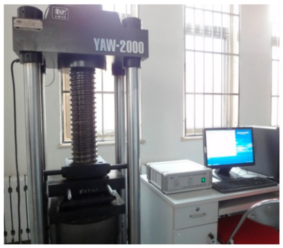
Figure 7.
TheYAW-2000kN-type computer-controlled automatic-pressure testing machine.
In this series of tests, four bags in the dimension of 0.25 m × 0.25 m × 0.06 m (length × width × height) were used. Each test group contains two bags which are consolidated, respectively, outdoors for 1 day and 3 days. Before the tests, a bag was selected randomly from each test group, and the moisture content of the tailing sand was measured. The other bag was placed on the bearing sheet of the test device. The vertical load was applied to the bag evenly until failure. The moisture content after the application of the vertical load was also measured.
As shown in Figure 8, the axial stress–strain relationships between vertical strain and vertical stress for the geotextile bags consolidated for 1 day and 3 days are demonstrated, respectively.
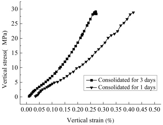
Figure 8.
The axial stress–strain curve.
According to the water content test, for the bags consolidated for 1 day, the water content of the geotextile bag is 24.2% before compression and 12.9% after compression. After 3 days of consolidation, the water content of the geotextile bag was 18.7% before compression and 11.1% after compression. According to Figure 8, with the gradual increase in vertical pressure, the tangent elastic modulus of the geotextile bag consolidated for 1 day and 3 days demonstrates the trend of increasing firstly, decreasing, and increasing at last. Such a trend is caused by the relatively low vertical pressure at the beginning of loading, without reaching the ultimate bearing capacity of the consolidated mortar in the bag. At this point, the tailings in the geotextile bag are under the vertical load, and the tailings in the bag are continuously compressed and compacted. As a result, the tangent elastic modulus of the geotextile bag is relatively large at the beginning. When the vertical load reaches a certain value, approximately 200 kN (3.2 MPa), the tailings in the geotextile bag begin to yield and suffer damage. However, the geotextile bag has not yet applied a binding force on the tailings. Consequently, the tangent elastic modulus starts to decrease, which continues until the geotextile begins to apply a binding force on the tailings. As the load continues to increase, the deformation of the tailings in the geotextile bag gradually increases. With a sufficient vertical load, the geotextile bag begins to constrain the tailings. Therefore, until the failure of the geotextile bag, the tangent elastic modulus is increasing gradually. According to the test, when the vertical pressure reaches approximately 1800 kN (28.8 MPa), the tearing failure of the geotextile occurs.
Furthermore, as shown in Figure 8, under the same vertical stress, the vertical strain detected in the geotextile bag after 1 day of consolidation is severer than the vertical strain detected in the bag with 3 days ofconsolidation. However, the differences in the ultimate bearing capacity for the bag consolidated for one day and three days are not significant.
3. The Stability Calculation of the Tailings Dam Using Geotextile Bags (TDGB)
The sub-dams of TDGB are constructed with geotextile bags. According to the tests discussed previously in this study, the tailing sand is considered a granular material with lower strength. However, the geotextile bag consisting of geotextile and tailing sand, which can work together under the vertical load, has demonstrated a much higher strength and hardly has a tear failure when the geotextile bag could be fully solidified. In the following stability calculation of TDGB, a geotextile bag is considered the overall material. For the TDGB as shown in Figure 9, the failure slip plane is usually through the layers between the geotextile bags without considering the tear failure of the geotextile bags. Namely, the most dangerous slip plane of the TDGB is made up of the line segment, which is a horizontal contact surface formed by geotextile bags and the arc segment in the tailing sand.
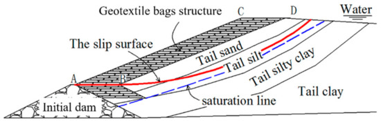
Figure 9.
Sketch map of the tailings dam constructed with geotextile bags.
As shown in Figure 10, assuming that the most dangerous slip plane of TDGB is through the contact surface AB, the assembly of these geotextile bags, such as the section ABCD, can act as an overburden on the tailing sand. To evaluate the stability of TDGB, the forces acting on the assembly of the geotextile bags and the section shown in Figure 10a are analyzed separately. The interaction force between the two sections can be solved by the static equilibrium and limit equilibrium conditions. The stability (such as the safety factor) of the section shown in Figure 10a,b is calculated separately. Finally, the stability formula of The TDGB whose failure slip plane is through a layer between geotextile bags can be obtained by superimposing the stability formulas of the two parts above.
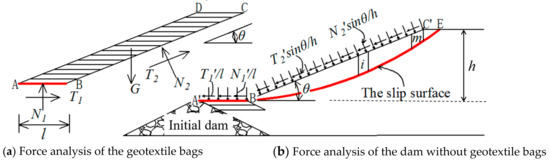
Figure 10.
Analysis of the tailing dam using geotextile bags.
The detailed analysis is listed as follows:
With the analysis of the load of the section ABCD, as shown in Figure 10a, the following three equilibrium equations can be obtained by the static equilibrium conditions.
The third balance equation of Equation (2) was obtained by calculating the moment about the midpoint of the segment AB.
Considering that the AB segment is a slip plane in the state of limit equilibrium, the following relationship is obtained.
where φ is the internal friction angle between the two geotextile bags.
The unknown forces , , , can be solved by the four equations above.
In the analysis of the section shown in Figure 10b, the forces , , and are considered to be distributed on the surface of and uniformly. According to the principle of force and reaction, , , , , taking , , , into consideration, the following equations are obtained.
When :
When :
Where: m refers to the number of slices on the surface B′C′. The force analysis of one of these slices i is shown in Figure 11:
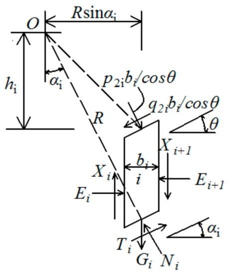
Figure 11.
The force analysis of slice i.
The force acted on slice i is in a state of static equilibrium in the vertical direction, which also follows the limit equilibrium condition about the safety factor . Therefore:
whereas
where li is the length of slice i bottom, and ci and ϕ are the cohesion and internal friction angle of tailings, respectively.
Taking moments about the center of circular slip surface, O, into consideration, the moment equilibrium equation of slide mass is calculated below.
Now, considering the moment balance of the body ABCD, the force acting on the section ABCD is shown in Figure 12. Surface AB, as a slip plane, follows the limit equilibrium condition about the safety factor .
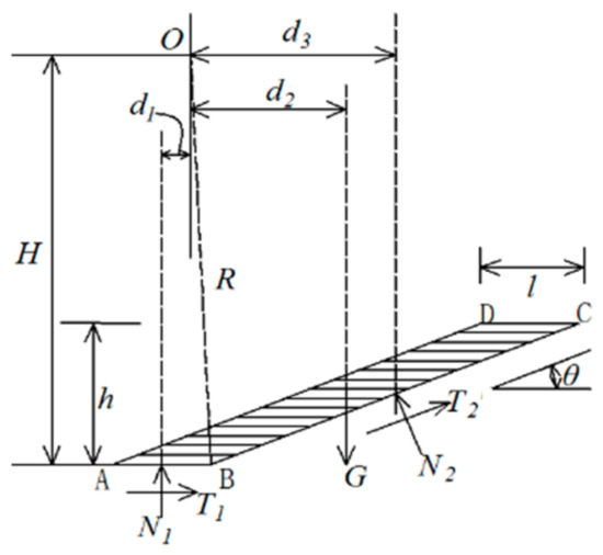
Figure 12.
Moment analysis of the ABCD section.
Taking a moment about the center of the circular slip surface (O) into consideration:
in Equation (7) and in Equation (8) refer to the interaction moment separately. So, combining Equations (7) and (8), the following equation is obtained as follows.
Substituting:
Combining Equations (4), (5) and (9), and considering , the stability formula of TDGB whose failure slip plane is through a layer between geotextile bags is obtained as follows:
Substituting:
When , , , , , the tailings dam with geotextile bags has become a conventional tailings dam. Equation (10) can be written as follows:
Equation (11) is the simplified Bishop formula in soil mechanics [38].
4. Some Calculation Examples
The TDGB, whose typical profile is shown in Figure 13a, was analyzed using Equation (10). To analyze and compare the stability of TDGB and the general tailing dam shown in Figure 13b, the general tailing dam has been calculated using Bishop’s simplified method.
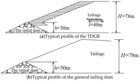
Figure 13.
Computational models.
As shown in Figure 13, the initial dam is a rockfill dam, with a height of 30 m, a bottom width of 124 m, and an inner and outer gradient of 1:2. Assuming that the initial dam is solid (excluding the instability and failure possibilities of the initial dam), the slope of the tailing dam in the upper part of the initial dam is 1:2.5. To study the influence of geotextile bags on the tailing dam directly, tailings are selected as tail sand only. The parameters of the tail sand, such as the unit weight, the inner friction angle, and the cohesion of the tail sand, were taken as 18.6 k N/m3, 24º and 8 kPa, respectively. The TDGB is the general tailing dam reinforced by the geotextile bags with 40 m, with the inner friction angle between tailings sand and geotextile bags taken as 30º from the previous shear test.
The TDGB and general tailing dam have been computed following the calculation program by MATLAB based on the methods discussed previously. The minimum factor of safety Fs was identified by the trial method. The calculation results are shown in Figure 14.
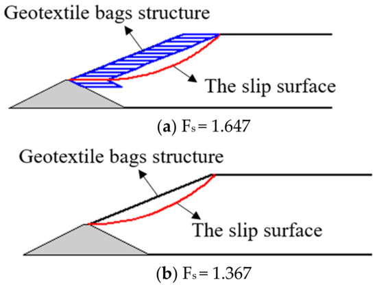
Figure 14.
The calculation results.
According to Figure 14, the sliding face with the maximum danger and the minimum safety coefficient about the TDGB and the general tailing dam are demonstrated. The minimum factor of safety Fs of the TDGB and the general tailing dam is calculated to be 1.647 and 1.367, respectively. Based on the calculation, the TDGB demonstrates better stability than the general tailings dam.
5. Discussion
In this paper, the experimental devices were designed to study the performance of geotextile bags, which are the main damming material of a new damming method. The stability safety factor of the tailing dam with geotextile bags is proposed creatively based on the simplified Bishop method. Some research has been done, but there are still many areas that need to be improved and further studied.
(1) Due to the limited test conditions, the size of the geotextile bags is small. Whether the test data obtained from the small-size bags can well represent the actual situation, and how to establish the relationship between the key mechanical parameters of the geotextile bags and the size of the geotextile bags, are the problems to be solved in the next step.
(2) This paper only considers the horizontal placement of geotextile bags. In the future, we can try to place the geotextile bags at a certain angle to analyze their stability.
6. Conclusions
In this study, the following conclusions are drawn based on a series of experiments conducted on the friction performance and compression performance of the geotextile bags body, as well as the overall stability analysis of the tailings dam with geotextile bags.
(1) According to the tests, a longer consolidation time of the geotextile bags tends to lead to lower water content and higher friction strength between geotextile bags.
(2) Based on the tests, a higher overburden pressure of the geotextile bag tends to lead to a greater anti-sliding stiffness between the geotextile bags. In addition, the failure between the geotextile bags follows the Mohr–Coulomb yield criterion.
(3) Under the circumstance that the geotextile bag is fully consolidated, the vertical ultimate bearing capacity of a single geotextile bag is considered to be high. For a single geotextile in the dimension of 0.25 m (length) × 0.25 m (width) ×0.06 (height), the ultimate compressive bearing capacity reaches as high as 28 Mpa.
(4) The assembly of geotextile bags on the tailing sand slope acts as an overburden. According to the calculated example, the increment of the safety factor Fs is approximately 20.5%, illustrating that the TDGB offers better stability than the general tailings dam.
In the future, some field experiments will be conducted to study the relationship between the size of the geotextile bags and the material properties. Different dam-filling methods will be studied to obtain the best dam-filling method and provide theoretical support for the design of a tailings dam with geotextile bags.
Author Contributions
Conceptualization, Q.L. and Y.L.; methodology, G.M.; resources, Q.L.; writing—original draft preparation, Q.L. and Y.L.; writing—review and editing, Q.L., G.M. and Y.L.; supervision, G.M. All authors have read and agreed to the published version of the manuscript.
Funding
This work is funded by the Special Fund of Fundamental Scientific Research Business Expense for Higher School of Central Government (Grant No. ZY20215127), Natural Science Foundation of Hebei Province (Grant No. 41807270) and Langfang Science and Technology Support Plan Project (Grant No. 2021013086).
Institutional Review Board Statement
Not applicable.
Informed Consent Statement
Not applicable.
Data Availability Statement
Not applicable.
Conflicts of Interest
The authors declare no conflict of interest.
References
- Glotov, V.E.; Chlachula, J.; Glotova, L.P.; Little, E. Causes and environmental impact of the gold-tailings dam failure at Karamken, the Russian Far East. Eng. Geol. 2018, 245, 236–247. [Google Scholar] [CrossRef]
- USGS. United States Geological Survey (Mineral Commodity Summaries): Phosphate Rock; US Government Printing Office: Washington, DC, USA, 2020. [Google Scholar]
- China Mineral Resources; Ministry of Natural Resources PRC: Beijing, China, 2020.
- Kossoff, D.; Dubbin, W.E.; Alfredsson, M.; Edwards, S.J.; Macklin, M.G.; Hudson-Edwards, K.A. Mine tailings dams: Characteristics, failure, environmental impacts, and remediation. Appl. Geochem. 2014, 51, 229–245. [Google Scholar] [CrossRef]
- Dong, T.; Cao, P.; Gui, R.; Lin, Q.B.; Liu, Z.Z. Experimental study on permeability coefficient in layered fine tailings under seepage condition. Geofluids 2021, 2021, 8850138. [Google Scholar] [CrossRef]
- Yin, G.Z.; Li, G.Z.; Wei, Z.A.; Wan, L.; Shui, G.H.; Jing, X.F. Stability analysis of a copper tailings dam via laboratory model tests: A Chinese case study. Miner. Eng. 2011, 24, 122–130. [Google Scholar] [CrossRef]
- Zhang, C.; Li, B.; Wu, F.H.; Yu, Y.; Zhang, Y.; Xu, H. Research on modification of mechanical properties of recycled aggregate concrete by replacing sand with graphite tailings. Rev. Adv. Mater. Sci. 2022, 61, 493–512. [Google Scholar] [CrossRef]
- Hegde, A.; Das, T. Finite element-based probabilistic stability analysis of rock-fill tailing dam considering regional seismicity. Innov. Infrastruct. Solut. 2019, 4, 37. [Google Scholar] [CrossRef]
- Yin, G.; Wei, Z.; Wang, J.G.; Wan, L.; Shen, L. Interaction characteristics of geosynthetics with fine tailings in pullout test. Geosynth. Int. 2008, 15, 428–436. [Google Scholar] [CrossRef]
- Azam, S.; Li, Q.R. Tailings dam failures: A review of the last one hundred years. Geotech. News 2010, 28, 50–53. [Google Scholar]
- Yang, Y.H.; Wei, Z.A.; Cao, G.S.; Yang, Y.; Wang, H.; Zhuang, S.N. A case study on utilizing geotextile tubes for tailings dams construction in China. Geotext. Geomembr. 2019, 47, 187–192. [Google Scholar] [CrossRef]
- Jiang, F.L.; Wu, H.N.; Liu, Y.; Chen, G.; Guo, J.J.; Wang, Z. Comprehensive evaluation system for stability of multiple dams in a uranium tailings reservoir: Based on the TOPSIS model and bow tie model. R. Soc. Open Sci. 2020, 7, 191566. [Google Scholar] [CrossRef]
- Du, Y.Q.; Xie, B.; Mullarney, B.; Zhang, C. Deposition of fine tailing particles and profile zoning of tailings dams. Soil Mech. Found. Eng. 2019, 56, 359–365. [Google Scholar] [CrossRef]
- Wang, W.S.; Yin, G.Z.; Wei, Z.A.; Jing, X.F.; Chen, Y.L. Analysis of the dynamic response and stability of fine-grained tailings dam by upstream embankment method in the area of high intensity earthquake. Chin. J. Rock Mech. Eng. 2017, 36, 1201–1214. [Google Scholar]
- Wu, S.C.; Zhao, Z.Q.; Zhang, X.Q.; Cheng, H.Y.; He, P.B.; He, F.Y. Stability analysis and reinforcement design of tailings dam expansion engineering. J. Kunming Univ. Sci. Technol. (Nat. Sci.) 2021, 46, 36–44. [Google Scholar]
- Yang, C.H.; Zhang, C.; Li, Q.M.; Yu, Y.Z.; Ma, C.K.; Duan, Z.J. Disaster mechanism and prevention methods of large-scale high tailings dam. Rock Soil Mech. 2021, 42, 1–17. [Google Scholar]
- Li, Q.Y.; Ma, G.W.; Li, P.; Su, Z.D. Contrastive analysis of dynamic response of tailings dam with and without geofabriform by shaking table model test. E3S Web Conf. 2020, 198, 01041. [Google Scholar] [CrossRef]
- Ye, E.J.; Duo, L.D.; Zhang, F.; Wang, X.Y. Application of geofabriform method damming technology in a tailings dam. Nonferrous Met. (Min. Sect.) 2020, 72, 47–50. [Google Scholar]
- Zhang, W.X.; Wang, M.L. Stability analysis based on geofabriform method and raising and expanding volume of a tailings dam. China Tungsten Ind. 2020, 35, 13–17. [Google Scholar]
- Xue, Z.Y. Feasibility analysis of Xipiao tailings dam with wide top constructed by mold bag method. Mod. Min. 2021, 37, 95–97, 101. [Google Scholar]
- Wang, P. Geofabriform Method; Water Resources and Hydropower Engineering Press: Beijing, China, 2006; pp. 20–21. [Google Scholar]
- Chu, J.; Yan, S.W.; Li, W. Innovative methods for dike construction: An overview. Geotext. Geomembr. 2012, 30, 35–42. [Google Scholar] [CrossRef]
- Yan, S.W.; Chu, J. Construction of an offshore dike using slurry filled geotextile mats. Geotext. Geomembr. 2010, 22, 422–433. [Google Scholar] [CrossRef]
- Oberhagemann, K.; Hossain, M.M. Geotextile bag revetments for large rivers in Bangladesh. Geotext. Geomembr. 2011, 29, 402–414. [Google Scholar] [CrossRef]
- Matsushima, K.; Mohri, Y.; Yamazaki, S.; Hori, T.; Ariyoshi, M.; Tatsuoka, F. Design of earth dams allowing temporary overtopping based on Hydraulic failure experiments and flood analysis. In Proceedings of the 4th Asian Regional Conference on Geosynthetics, Shanghai, China, 18 June 2008. [Google Scholar]
- Xu, Y.F.; Huang, J.; Du, Y.J. Earth reinforcement using soilbags. Geotext. Geomembr. 2008, 26, 279–289. [Google Scholar] [CrossRef]
- Liu, S.H.; Wang, Y.S. Reinforcement mechanism of soilbags and its applications. Geotech. Eng. Tech. 2007, 21, 221–225. [Google Scholar]
- Yang, J.X.; Hu, J.; Wu, Y.W.; Zhang, B.Y. Numerical Simulation of Seepage and Stability of Tailing Dams: A Case Study in Ledong, China. Sustainability 2022, 14, 12393. [Google Scholar] [CrossRef]
- Bai, F.Q.; Liu, S.H.; Wang, Y.Q. Research on reinforcement mechanism and failure strength of soilbags. Rock Soil Mech. 2010, 31, 172–176. [Google Scholar]
- Qiu, C.L.; Yan, S.W. Mechanical behavior analysis of large scale geofabriform. Eng. Mech. 2009, 26, 92–97. [Google Scholar]
- Wang, M. Study on deformation and mechanical properties of geotextile tube. Master’s Thesis, Zhejiang University, Hangzhou, China, 2013. [Google Scholar]
- Lohani, T.N.; Matsushima, K.; Aqil, U.; Mohri, Y.; Tatsuoka, F. Evaluating the strength and deformation characteristiccs of a soil bag pile from full scale Laboratory tests. Geosynth. Int. 2006, 6, 246–264. [Google Scholar] [CrossRef]
- Liu, S.H.; Matsuoka, H. A new earth reinforcement method by soilbags. Rock Soil Mech. 2007, 28, 1665–1670. [Google Scholar]
- Wang, Y.Q.; Liu, S.H.; Yang, J.J. Model test of sandy soil slope reinforced by soilbags and upper-bound solution. Chin. J. Rock Mech. Eng. 2009, 29, 4006–4013. [Google Scholar]
- Liu, S.H.; Bai, F.Q.; Wang, Y.S.; Wang, S.; Li, Z. Treatment for expansive eoil channel slope with soilbags. J. Aerosp. Eng. 2013, 26, 657–666. [Google Scholar] [CrossRef]
- Matsushima, K.; Aqil, U.; Mohri, Y.; Tatsuoka, F. Shear strength and deformation characteristics of geosynthetic soilbags stacked horizontal and inclined. Geosynth. Int. 2008, 2, 119–135. [Google Scholar] [CrossRef]
- Huang, C.-C.; Matsushima, K.; Mohri, Y.; Tatsuoka, F. Analysis of sand slopes stabilized with facing of soilbags with extended reinforcement strips. Geosynth. Int. 2008, 4, 232–245. [Google Scholar] [CrossRef]
- Chen, Z.Y.; Zhou, J.X.; Wang, H.J. Soil Mechanics; Tsinghua University Press: Beijing, China, 1994. [Google Scholar]
Disclaimer/Publisher’s Note: The statements, opinions and data contained in all publications are solely those of the individual author(s) and contributor(s) and not of MDPI and/or the editor(s). MDPI and/or the editor(s) disclaim responsibility for any injury to people or property resulting from any ideas, methods, instructions or products referred to in the content. |
© 2023 by the authors. Licensee MDPI, Basel, Switzerland. This article is an open access article distributed under the terms and conditions of the Creative Commons Attribution (CC BY) license (https://creativecommons.org/licenses/by/4.0/).