Article

Proposal for Implementation of Extraction Mechanism of Raw Materials during Landfill Mining and Its Application in Alternative Fuel Production

by
Inna Pitak
1,*,
Gintaras Denafas
1,
Arūnas Baltušnikas
1,
Marius Praspaliauskas
2 and
Stasė-Irena Lukošiūtė
1
1
Laboratory of Materials Research and Testing, Lithuanian Energy Institute, Breslaujos st. 3, LT-44403 Kaunas, Lithuania
2
Laboratory of Heat-Equipment Research and Testing, Lithuanian Energy Institute, Breslaujos st. 3, LT-44403 Kaunas, Lithuania
*
Author to whom correspondence should be addressed.
Sustainability 2023, 15(5), 4538; https://doi.org/10.3390/su15054538
Submission received: 25 January 2023 / Revised: 24 February 2023 / Accepted: 28 February 2023 / Published: 3 March 2023

Abstract

:
New approaches to waste management and the demands of the circular economy have changed the management of landfills. Over time, the decomposition of buried waste primarily determines the amount of recyclable and combustible materials. This pilot study attempted to assess the feasibility of extracting and recovering energy-intensive raw materials from landfills by developing a waste extraction mechanism and creating a solid recovered fuel (SRF) production line for use as a replacement fuel in the cement industry. The proposed mechanism consisted of two stages. The first stage was recommended to be carried out on the landfill territory by screening out the fine fraction and extracting inert materials and bulky waste. The second stage should be on the mechanical biological treatment (MBT) plant’s territory by adding additional technological equipment to the MBT line. The productivity of the SRF production line was calculated and was 4.9 t/h. The mechanism proposed in the work was tested at the operating test site in Lithuania. The composition of Landfill Mined Residues (LMRs) was studied, and the energy potential of the studied part of the landfill was calculated, which was 196,700 GJ. It has been found that the SRF produced complies with the European Union (EU) standard and, according to its classification characteristics, belongs to class III and can be used as a replacement fuel in the clinker firing process. An environmental and economic efficiency assessment was conducted using SRF in the cement kiln. The calculation result showed that using 10% SRF as a replacement fuel for coal used in clinker firing at 2.51 t/h would save 1274 USD/h in coal costs. This use of SRF will emit 3.64 t/h CO2 and achieve a net savings of 1355 USD/h. The mechanism proposed in this work aimed at reducing waste in landfills by converting materials into energy resources will help achieve the circular economy’s goals.

1. Introduction

In recent years, the waste management industry has experienced rapid development, setting increasingly ambitious environmental goals for the future and working towards the rational use of waste as a resource, especially as an energy resource [1].
The waste management hierarchy indicates the order of preference for actions to reduce and manage waste and aims to extract the maximum practical benefit. In the waste hierarchy, prevention, minimization, recycling and energy recovery are preferred over landfills, which remain the last option in waste management [2]. According to the statements of Eurelco [3], by 2030, at least 65% of household waste should be recycled, and waste disposal in landfills should be reduced to 10% or less by 2035. While the waste landfilling will be minimal in the near future, huge amounts of various materials are accumulated in the operating and closed landfills over the long term. We must consider options to extract resources from the anthroposphere. Landfill mining (LFM) will ensure that material and energy recovery goals are met throughout the life cycle of a landfill. This concept of LFM is supported by several organizations [4]. In the field of LFM research, several problems can be faced, such as technological, the need to address the conditions for implementation and the development of a standardized framework for assessing economic and environmental indicators [5]. Mining existing and future landfills can lead to secondary materials and energy flow, reducing the area it covers [6,7,8]. The above shows that landfill mining corresponds with the EU Roadmap for a Resource Efficient Europe, which provides no land acquisition by 2050.
According to the authors’ statements [9,10,11], LFM is presented as a process that provides additional materials and energy sources. However, LFM has recently become a topical subject for research resource potential [12], technical [13] and economic aspects [14]. While the number of LFM projects is relatively small, a fair amount of data about the composition of landfills and recoverable resources has been collected and presented in recent years [15,16,17]. Currently, the discussion of the feasibility of the LFM and the search for the optimal use of resources continues, moving from the conceptual stage to the modeling stage by building different models, conducting a comparative assessment of alternatives and finally choosing the optimal option and implementation of it “in life”. Physical investigations of the composition of the landfill are mandatory and serve as a form of input or verification of available data, as in the study of Hossain and DeVries [18]. Material flows are an essential component of the economic evaluation of LFM. The economic value of the LFM process can have positive and negative effects, such as in the results of Kieckhäfer et al. [19]. However, financial analysis alone cannot be decisive in assessing the economic feasibility of applying LFM. The innovative development of the LFM has highlighted the relevance of several aspects, such as biochemical flows, management, business dynamics, infrastructure and markets [20]. For the LFM, economic system and material flow models were developed, and life cycle assessments were created and calculated to assess the impact of the LFM process on the environment. Emphasis was placed such that the feasibility of the LFM would be most effective if separation methods were improved, the need for land development increased and resources became in short supply.
Based on the early-developed models and strategies, considering the lack of energy resources, there is an increasing discussion of using LFM as a tool for extracting energy resources and their use as an alternative fuel in energy-intensive industries. There are results of many researchers who also considered the issue of producing alternative fuels for the cement industry. Mustafa Kara [21] considered the production of refuse-derived fuel (RDF) from the non-recyclable waste fraction and studied its potential as a replacement fuel in the cement industry. Hemidat et al. [22] studied the production and disposal of RDF obtained from mixed waste using bio-drying and subsequent use of the produced fuel in the Jordanian cement industry. Dase et al. [23] explored the potential of the RDF in terms of waste generated and the amount of landfill waste. Garces et al. [24] investigated the potential of various landfill wastes and the possibility of extracting Landfill Mined Residues (LMRs) and SRF production. All the described studies pursue one goal—disposing of newly generated waste and recovering energy resources.
The characterization of LMRs strongly depends on the type of waste disposed (domestic or industrial), the climate zone and the landfill’s age [25,26]. Since the raw material extracted from the landfill is specific, non-standard technology must be developed for the extraction LMRs. Moreover, it must be prepared before raw materials can be used as an energy resource.
This study focused on developing a mechanism for extracting LMRs, studied the possibilities of producing alternative fuel and its characteristics and used it in the cement industry as a replacement fuel during the clinker firing process. It also determined the composition and the main characteristics of the LMRs at various depths of the landfill and established the optimal depth from which LMRs can be extracted. Moreover, the article calculates the energy potential of the studied part of the landfill. It developed the technological line for SRF production, studied ash after the incineration of SRF and established that it contains the inorganic component, clinker-forming minerals and crystal structure. The developed mechanism will contribute to extracting, from LMRs, a high-calorific fraction and producing alternative fuel for energy-intensive industries.

2. Materials and Methods
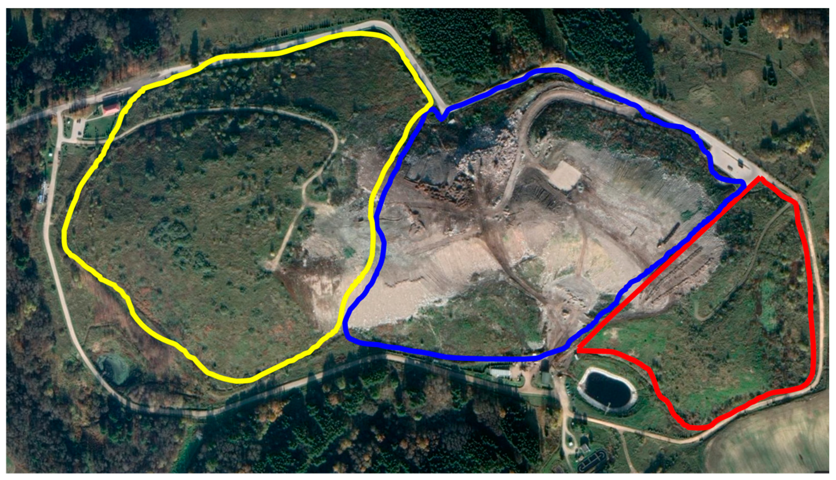
2.1. Study Area

The Kaunas regional non-hazardous waste landfill (Figure 1) was established in 1973. It covers an area of 37.4 hectares. The landfill utilizes mixed domestic waste for Kaunas city and other municipalities in the country (Lithuania).
Waste is accepted to the landfill based on the waste management agreement. The landfill territory consists of a waste disposal zone (landfill), a service zone and a prospective zone for leachate collection and treatment. The landfill itself consists of three sections. Section I (N 54°59′47″ E 24°01′51″) is the oldest and is decommissioned and reclaimed; Section II (N 54°99′65″ E 24°03′08″) is in operation and consists of five sections for waste disposal, separated from each other by barriers 2.4 m high. Section III (N 54°99′79″ E 24°02′80″) is reclaimed and has a separate site for the disposal of asbestos-containing waste with an area of 0.25 ha.

2.2. Test Instrument

The composition of unprocessed LMRs was determined through manual sorting after drilling and excavating. The studies were conducted according to the Standard Test Method for Determining the Composition of Unprocessed Municipal Solid Waste (ASTM D5231-92(2016). Excavated materials were sieved to fine (<20 mm) and course (>20 mm) fractions. The fine fraction was backfilled. The coarse fraction was sorted. Afterwards, the coarse fraction was processed for material recovery whenever possible (e.g., plastic, wood, rubber and others) and used as materials to produce alternative fuels.
The drillings were carried out at the landfill with a 15cm drill on the landfill sections; waste samples were taken every two meters at a depth of 1 to 20 m. In Section I, drilling was carried out up to 10 m, in Section II, up to 14 m, and in Section III, up to 20 m. The drilling depth was determined on-site at the time of the study. The difficulty in drilling was that there used to be a dump of armored vehicles on the territory of the current landfill. This place had a huge ravine, which eventually turned into the largest landfill.

2.3. Testing LMRs

After drilling, the material was obtained and subsequently subjected to research to prove the feasibility of extracting LMRs from the landfill and using it as an alternative fuel. The samples of LMRs were shredded and mixed and, after these manipulations, tested. The samples were heterogeneous, and their composition may have fluctuated. The following studies have been carried out:
Moisture content (MC)—CEN/TS 15414-2:2010 [27];
Ash content (AC)—EN ISO 21656:2021 [28];
Volatile matter (VM)—EN ISO 18123:2015 [29];
Net calorific value (NCV)—EN ISO 21654:2021 [30];
Chlorine content (Cl)—EN 15408:2011 [31];
Mercury content (Hg)—EN 15411:2011 [32];
SEM-EDS analysis of ash;
XRD–Rietveld refinement analysis was carried out on a BRUKER D8 ADVANCE diffractometer with CuKα radiation at 40 kV in a 2Θ (5°÷70°) interval at a scanning step 0.02° and with the Topas program;
The ash morphology and elemental analysis were investigated using scanning electron microscopy equipped with an energy-dispersive spectroscopy detector (SEM-EDS). The analyzed samples were passed through sieves and then dried at 40 °C. Before the morphological observation, the ash specimens were coated using gold (Au) to obtain SEM images. SEM observation of samples was performed on a ZEISS EVO MA10 microscope at an accelerating voltage of 20 kV. The Bruker AXSX Flash 6/10 Detector can display all elements present in the specimen at an overall accuracy of about 1% and detection sensitivity down to 0.1% by weight;
The quantity element analysis of LMRs was performed using an ICP-OES, Optima 8000 (Perkin Elmer). The samples (0.4–0.5 g) were mineralized with 8 mLof concentrated nitric acid, 1 mLof hydrofluoric acid and 3 mLof hydrogen peroxide at 800 W, 6 MPa and pRate: 50 kPa · s−1 (Multivalve 3000). After the mineralization, the solution was poured into 50 mL flasks and diluted to 50 mL using deionized water. A quantitative analysis mode was used for the data acquisition of the samples. The scanning of every sample during element analysis was repeated three times to gather reasonably good results. Analysis was made in four replicates of each sample.

2.4. Energy Potential of Combustible Fractions

The energy potential of LMRs depended on the moisture content and chemical composition and was calculated based on Equations (1)–(4). In this work, we recommend calculating the energy potential of the waste fraction using Dulong’s equation [33]. The first thing to do is calculate HCV for each waste fraction, according to Equation (1):
HCVi = 338 · C + 1442 · [H − (O/8)] + 94 · S
where HCVi—high calorific value of each fraction of dry waste; C, H, O, S—content of chemical elements in the waste fraction, %.
The chemical composition of the waste fractions was calculated from the elemental composition based on the data of Reinhart D.R. [34].
The lower calorific value (LCVi) of the dry waste fraction was calculated by subtracting the amount of energy required to evaporate water from each fraction of waste [35]:
LCVi = HCVi − [24.41 ∙ (18.015/2.015) ∙ MCi]
where LCVi—lower calorific value of each fraction of waste, kJ/kg; MCi—moisture content of fraction of waste, %; 24.41—coefficient based on the “secret” heat of vaporization of water, where l = 2441 kJ/kg at 25 °C; 18.015—the molar mass of water, g/mol; 2.015—molar mass of hydrogen, g/mol.
The lower calorific value of the wet waste of each fraction was calculated according to [35]:
LCVi(wet) = LCVi ∙ [(100 − MCi)/100] − 24.41 ∙ (100 − MCi)/100]
where LCVi(wet)—lower calorific value of each wet fraction of waste, kJ/kg.
The total energy potential of a combustible fraction of LMRs was calculated according to the data of the World Bank [35]:
E = [ΣLCVi(wet) ∙ SWi] ∙ η ∙ 0.278 ∙ 10−6
where η—energy efficiency when burning excavated combustible materials for heat production is 85%; SWi—the amount of the incinerated waste fraction of each fraction, kg; 0.278—conversion factor from MJ to kWh (1 MJ = 0.278 kWh).

2.5. Development and Calculation of SRF Production Line

Based on the data obtained from the drilling at the landfill, the SRF production line was developed, and the flow rate was calculated. To produce SRF from the LMRs, they must undergo several stages of preparation so that the resulting alternative fuel meets the EU standard and can be used in energy-intensive industries. The main stages of SRF production are extracting prohibited materials, metals, inert materials, glass and fine fractions. The moisture contained in the waste must be removed; combustible materials must be crushed (d < 20 mm). The flow rate of the SRF production line was calculated using Equations (5)–(10), considering parameters from the SRF production line that we developed.
FRSRF = ΣLMR − F1 − F2 − F3 − F4 − Wlost
F1 = (ΣLMRs · Q1)/100%
F2 = [(ΣLMRs − F1) · Q2]/100%
F3 = [(ΣLMRs − F2) · Q3]/100%
F2 = [(ΣLMRs − F3) · Q4]/100%
Wlost = [(ΣLMRs − F4) · MCLMR]/100%
where FRSRF is the estimated consumption of the production line of the SRF production (t/h); ΣLMRs is the flow rate of waste after drilling from a landfill (14.2 t/h); F1, F2, F3 and F4 are the flow rate ΣLMRs after the extraction of metals (ferrous and non-ferrous), inert materials, glass and a fine fraction (t/h); Q1, Q2, Q3 and Q4 are the quantity of extracted materials at each stage of separation (%); MCLMRs is the quantity of moisture contained in LMRs (%); Wlost is the LMRs flow after moisture loss (t/h).

3. Results

3.1. Granulometric and Morphological Analysis

According to the data obtained in the course of research (as a result of drilling), the granulometric characteristic of the LMRs was obtained (Figure 2). In all sections of the landfill (I–III), a fine fraction predominates, regardless of the depth of the waste.
For Section I (up to 10 m), the size of the coarse fraction (d > 80 mm) was from 0.09 to 27.34%. The less coarse fraction of LMRs (80 > d > 40 mm) was from 2.75 to 16.02%, and the size of 40 > d > 20 mm was from 5.43 to 10.2%. Depending on the depth, a total fraction of more than 20 mm for Section I ranged from 3 to 47%. The minimum amount of the coarse fraction and the predominance of the fine fraction in this section refer to the upper layer of the landfill and are explained by the fact that this section of the landfill is re-claimed.
Section II is currently active (up to 10 m) comprising LMR fraction sizes of more than 20 mm from 0.72 to 15.47%. Therefore, for a depth of 11 to 14 m, the coarse fraction was less than that at a drilling depth of up to 10 m. The quantity of the coarse fraction (diameter of more than 20 mm) ranged from 0.5 to 6.12%.
For Section III (up to 10 m), along with the fine fraction, there is also a coarse fraction; however, its amount is much less than that of the fine fraction, and its value was in the range of 4.4 to 42.44%. The fraction size distribution of LMRs changed with an increased drilling depth. Thus, the fine fraction dominated for depths from 11 to 20 m; a coarse fraction presented but in a lower amount than that at a depth of up to 10 m and was from 0.37 to 12.77%. Such a granulometric composition of the considered sections of the landfill is due to the composition of the waste taken to the landfill for deposition and the residence time of this waste at the landfill. Obtained results about the granulometric composition and amount of fine fraction of LMRs correspond to the research study [36,37].
The LMR characterization is based on the methodology of the European Commission [38]. LMRs were divided into 12 primary categories. Regardless of the drilling depth, the composition of the LMRs from all landfill sections showed that the fine fraction predominated. Based on the methodology of EN 15415-1:2011 [39], obtained results of compositions of LMRs are presented in Figure 3.
The results of the analysis show that the total waste composition for Section I consisted of plastics by up to 5.87%, rubber by up to 2.28%, textiles by up to 16.64%, wood by up to 3.07%, metals by up to 6.59%, glass up to 0.84% and inert materials up to 1.47%, and the content of the fine fraction at some depths was up to 97.16%.
A similar situation occurred with the composition of the LMRs for Section II. The composition of the waste was as follows: plastics up to 10.03%, rubber up to 0.6%, textiles up to 9.16%, paper up to 2.73%, wood up to 9.58%, metal up to 17.4%, glass up to 1.77% and inert materials and fine fraction up to 1.99% and 94.98%, respectively.
For Section III, the composition was as follows: plastics up to 16.13%, rubber up to 0.44%, textiles up to 39.84%, paper up to 1.21%, wood up to 1.73%, metal up to 9.14%; the amount of glass, inert materials and the fine fraction were up to 1.08%, 5.55% and 95.07%, respectively.
Based on the results of the morphological analysis of LMRs, it is possible to trace the trend in the commissioning of the MBT plant.
Figure 3 shows the general characteristic of the LMRs with fine and coarse fractions. According to it, we can conclude that the predominant material is the fine fraction for all three sections (wells), and the presence of textiles in the studied samples ranks second. Soft, hard plastics and metal occupy the third, fourth and fifth places in terms of content in the material under study. The investigated fraction also was observed to have multilayer composites, rubber, paper, wood, glass, inert materials and other burnable fractions. Their amount in the studied material did not exceed 5%. After extracting the fine fraction from LMRs, a combustible fraction, RDF, was obtained. Figure 4 shows the amount of the total combustible fraction. The research results correlate with the data [40,41] obtained in studies of landfills in European countries.
The primary materials that make up the combustible fraction are plastics (soft and hard), rubber, textiles, paper, wood, multilayer composites and other materials. The combustible fraction was mainly represented by textiles and contains the least multilayer composites. The results allowed us to consider the landfill a “potential energy object”.

3.2. Physicochemical Properties of Potential Fuel

After extracting the fine fraction and large inert materials from the LMRs, the resulting potentially combustible fraction will be called RDF. It is a non-defined term and refers to waste that has not undergone proper processing. RDF is not standardized, and features (composition, contaminants, calorific value) are undetermined [42]. This combustible fraction (RDF) had high humidity and contained prohibited materials (chlorine-containing plastics, inert materials, metals, e.i.). In such conditions, the RDF cannot be used as an alternative fuel in the intensive-energy industries. RDF can be used only for incineration to obtain heat or energy. The combustible fraction after extraction of the fine fraction from LMRs had the same characteristics for developed and developing EU countries [10].
After carrying out several technical operations with RDF, we will be able to obtain SRF. SRF is fuel from waste produced and tested according to EU standards. Its features are well specified, and following that, SRF is classified. SRF is produced under the producer’s regime of a quality assurance scheme [42]. Stages for preparing SRF from RDF, which meet the EU standard, should include the following stages: extraction of prohibited materials, metals, inert materials, shredding and drying.
Moreover, the first thing you need to start analyzing fuel from waste should be measuring the main calorific characteristics. Based on these results, we can conclude the possibility of using this fuel as an alternative. The results of the main properties of RDF that were obtained after extracting the fine fraction from LMRs are presented in this section. First, MC, AC and NCV were measured and are illustrated in Figure 5, with the results of determining Cl- and Hg- content in Table 1.
The main properties of any waste, especially those representing energy potential, are in Section 2.3 and are moisture content (MC), ash content (AC), volatile mater (VM) and net calorific value (NCV). These properties depend on the waste’s morphological composition, the year’s season, and many other conditions.
The MC of RDF significantly influences the choice of recycling to SRF technology and depends on many factors, including the RDF composition. The MC of RDF at the entire considered depth of the landfill was measured. Thus, for Section I, at a depth of 1 to 10 m, the MC of the materials ranged from 18.05 to 74.01%. For Section II, at a depth of 1 to 10 m, it ranged from 22.32 to 35.38%, and a depth of 11 to 14 m, it ranged from 38.34 to 45.06%. For Section III, at the considered depth from one to 10 m, it went from 40.48 to 60.14%, and at a depth of 11 to 20 m, it ranged from 36.53 to 84%. From the presented results of the study, it can be concluded that with an increase in the depth of the waste, the MC of the excavated LMRs and, consequently, the obtained RDF also increase by the possible retention of moisture in deeper layers of the landfill.
The AC represents the fireproof component remaining after a sample is combusted. In this analysis, one gram of the sample was put into a crucible and placed in a furnace. The furnace was heated to 950 °C, and the samples were kept for one hour. Further, after cooling and weighing, the AC was calculated according to EU standards and presented in Figure 5. In addition to the oxidation of organic matter, in this temperature range during combustion, chemical reactions occur in minerals, such as the hydration and decomposition of carbonates, sulfates and other sulfur compounds. The amount of ash depends on the content of organic and inorganic substances and possible impurities. The AC varied following the presence of materials that were part of the studied fraction. Therefore, for Section I at a depth of 1 to 10 m, the AC ranged from 13.4 to 33.38%; for Section II at a depth of 1 to 10 m, it was from 3.77 to 21.22%; for the same section of the landfill, but a depth of 11 to 14 m, it ranged from 27.89 to 32.42%. Section III was considered at depths from 1 to 10 m and 11 to 20 m; the AC for these depths was 21.07 to 39.81% and 22.78 to 45.48%, respectively. Based on the results, we can say that the AC of RDF strongly depends on the AC of landfilled materials, the nature and time of their decomposition in the landfill and particles of the fine fraction stuck on the excavated LMR surface.
The VM is the part of organic matter that is transformed into gas when heated, such as hydrocarbons, hydrogen, oxygen, carbon oxide and other non-combustible gases resulting from the thermal decomposition of materials. The VM of RDF has a high value because of the increased oxygen, which can be seen in Figure 5. For landfill Section I, the VM value ranged from 40.22 to 69.56% at a depth of 1 to 10 m. For Section II, for the considered drilling depth (from 1 to 14 m), the VM was in the range of 55.42 to 85.7%. For Section III, at a depth of 1 to 10 m, the VM ranged from 50.9 to 66.15%; for depths of 11 to 20 m, it went from 26.83 to 56.23%. Fuel containing a large amount of VM is unfavorable because it releases more tar, which condenses at ambient temperature and causes problems in equipment operation.
The NCV of fuel depends upon the nature of the fuel and the relative proportions of the elements present. Figure 5 shows that the NCV of the RDF directly depends on the materials of the considered fraction at a certain depth. There were presented measurements of NCV for RDF: Section I ranged from 7.76 to 17.43 MJ/kg; Section I went from 13.69 to 24.48 MJ/kg. For Section III, at a depth of 1 to 10 m, the NCV consisted of 12.22 to 14.94 MJ/kg, and at a depth of 11 to 20 m, it was from 12.21 to 18.3 MJ/kg. It can be concluded that the main factors affecting the calorific value of RDF are the humidity and burnable part of the landfilled waste.
The chlorine content was quantitatively investigated in three landfill sections at different depths and presented in Table 1. Thus, for Section I, the chlorine content at a depth of 1 to 10 m was 0.54 to 4.32%. For Section II, at a depth of 1 to 14 m, the chlorine content was 0.16 to 1.8%. The considered Section III of the landfill had the following values of chlorine content: at a depth of 1 to 10 m, from 0.072 to 0.469%; the value of the chlorine content for a depth of 11 to 20 m was in the range from 0.091 to 1.459%. The presented data indicate that the chlorine content directly depends on the materials included in the RDF that were taken to the landfill for disposal and did not depend on the depth of the waste.
Managing Hg emissions for incinerators is essential since more than 78% of municipal solid waste (MSW) is incinerated today. The total Hg content in waste samples obtained from Section I of the landfill from a depth of 1 to 10 m shows that the Hg content does not depend on the depth of the waste and relies on the presence of Hg-containing materials in the waste and was in the range from 0.02 to 0.106 mg/kg−1. For Section II, the mercury content was 0.02 mg/kg−1 at the depth under consideration. For Section III, the Hg content in the RDF obtained during drilling at a depth of 1 to 10 m had a value of 0.02 to 0.304 mg/kg−1. Nevertheless, with an increasing depth, the Hg content at 11 to 20 m was less than 0.02 mg/kg−1. The characteristics of RDF practically had the same value as the characteristics of municipal solid waste from one of the largest landfills in Kazakhstan [43].
Powder diffraction is a scientific method using X-ray, neutron or electron diffraction to determine the structural characteristics of materials. The XRD–Rietveld refinement method was used for phase identification, quantitative analysis and complete crystal structure analysis. X-ray diffraction analysis of the RDF ash from different landfill sections and depths was carried out, and the obtained X-ray patterns were deciphered using the Diffract Eva program. The results of the XRD analysis are presented in Figure 6.
Figure 6 shows an X-ray pattern (2θ = 5°–70°) of control samples of ash obtained after incinerating RDF from landfill sections. The X-ray diffraction analysis of ash based on the Rietveld refinement method (using the Topas program) is presented in Table 2.
According to the data in Figure 6 and Table 2, it can be seen that 11 compounds found during the analysis were present in all studied sections of the landfill, except for Section I. In this section, no perovskite compound was found. The found compounds differed in quantitative composition. The data from X-ray diffraction analysis allowed us to conclude that the ash obtained after the combustion of RDF contains minerals that are part of the clinker. Moreover, these data will enable us to consider RDF as a resource for obtaining alternative fuel that meets the EU standard. Results of mineralogical analysis of compositions showed similarity for some minerals, quartz and microcline anorthite, with results of Daniel Vollprecht et al. [44].
Elemental oxide analysis, based on SEM/EDS measurements, is presented in Table 2. SEM/EDS analysis of ash made it possible to determine chemical elements and calculate the composition of the oxides. Data from Table 2 prove that ash consists of the inorganic part, and the oxide composition of ash corresponds to the oxide composition of the clinker, but in different quantities [45].
According to Table 3, it was found that the oxides of Ca, Fe, Si, Al and Mg are dominant in the oxide composition of the ash; their amount was more than one wt.%. The content of Na-, S-, K-, Ti-, and Mg oxides in the ash was less than one wt.%. Thus, according to [46], the ash obtained by combusting RDF does not contain prohibited oxides and gives us the prerequisites for creating an alternative fuel that will be prepared and, in the end, will comply with the EU standard.

3.3. Development of Concept for SRF Production Line

Based on the obtained results, the concept for an SRF production line was developed and presented in Figure 7. The flow rate of the SRF production line was calculated with Equations (5)–(10) and amounted to 4.9 t/h.
The LMRs extraction and SRF production mechanism we developed consisted of two stages. The first stage involves extracting inert, huge materials and the fine fraction on the landfill territory using a drum sieve. The amount of the fine fraction separated from the LMRs is 43%. In the second and final stage, re-extraction of the fine fraction and SRF production is proposed to be carried out on the territory of the Kaunas MBT to reduce capital costs. In the second stage of SRF production, another 50% part of the fine fraction is removed via secondary sieving. At the end of the second stage, the fine fraction content was 1.3%. The second stage will contain six additional units. Each unit plays an important role.
After removal of fine fraction extraction and coarse inert material, the materials are sent for the extraction of ferrous and non-ferrous metals. With a magnetic separator, ferrous metals were extracted, and an eddy current separator was used for non-ferrous metals. After the extractionof metals, the material is shredded up to 40 mm until a homogeneous material is obtained. After the shredding stage, the material is sent to a repeated drum sieve to homogenize and detect large particles. Material more extensive than 40 mm is sent for shredding to achieve the required size. At the end of the shredding stage, the moisture content of the material decreased by 86.7% and amounted to 2.5%.
A drying chamber is provided at the end of the production line. Tumble-drying is the optimal method, as it has low capital costs, is easy to operate and allows one to produce large volumes of products. Characteristics of the produced SRF are shown in Figure 8. The amount of the fine fraction, MC, AC, VM and NCV amounted to 1.3 wt.%, 2.5 wt.%, 44.3 wt.%, 34.8 wt.% and 16 MJ/kg, respectively. The data obtained indicate that separating the fine fraction through double sieving significantly improves the characteristics of the obtained SRF.
According to data [47,48], fuels are hydrocarbons comprised primarily of the following elements: carbon and hydrogen and some sulfur, nitrogen, oxygen and mineral matter in the next interval, with the C content from 20 to 70 wt.%, H from 3 to 8 wt.% and N from 1 to 5 wt.%. As seen in Figure 8, the SRF is a favorable combination of the C, H and N content for combustion. As for sulfur, the sulfur content in the analyzed materials was within the usual range for this element (0.2–1 wt.%). Regarding the halogen elements, a chlorine concentration was measured and amounted to 0.02 wt.%. The Hg-content in produced SRF was within acceptable limits for this fuel and complied with the allowable limits for use in cement kilns.
It was also found that the ash obtained after incinerating SRF had a crystalline structure and contained crystalline calcium-, sodium-, potassium-, iron- and silicon-bearing phases. The crystalline phase in materials is favorable for clinker production (Figure 9).
Material morphology and particle size characteristics are associated with their crystal structure features. In our case, the ash particles had a different color, changed with depth from light grey to dark grey and had a lamellar and crystal shape. Ash particles had a size range of 1–20 μm and were not steadily distributed.
Quantity element analysis of RDF (obtained via extraction of the fine fraction and huge inert materials from LMRs) and SRF obtained through re-extraction of the fine fraction, inert and prohibited materials showed that metals consisted of 14 elements: Al, Ca, Cd, Cr, Cu, Fe, K, Mg, Mn, Na, P, Si, Ti, Zn (Figure 10). The dominant elements were Si, Ca, Fe, K, Na and Mg. The predominant presence of these elements is due to the composition of the waste once taken to the landfill.In their study, the authors of Jagodzinska et al. [49] also found chemical elements, such as K, Na, P, Cd, Cr, Mn and Ti.
Silicon is a dominant element in the ash. The quantity of silicon in the RDF was 406,861 mg/kg, and in SRF, it was 208,655 mg/kg. From the obtained data, we can see that the amount of silicon in SRF decreased to 48.7%; the double extraction of the fine fraction conditions this decrease. Calcium was in second place, containing chemical elements in the ash. The quantity of calcium in RDF amounted to 162,031 mg/kg, and in SRF, it was 86,575 mg/kg. The iron was in third place in terms of its content in the prepared SRF. The quantity of iron in SRF decreased to 21.8% compared with the RDF content and amounted to 17,435 mg/kg. The amount of potassium in the SRF decreased by 26.5% and amounted to 9448 mg/kg. Sodium was also present in the prepared SRF but at a lower concentration than silicon. As a result of the re-extraction of the fine fraction, sodium in the ready SRF decreased by 8.4% and amounted to 5474 mg/kg. Sufficiently high magnesium concentrations in SRF indicate the presence of ceramics, inert materials and garden waste. The magnesium content in SRF decreased by 10.7% and amounted to 3516 mg/kg.
As for the other elements present in the obtained SRF, their amount was reduced through double extraction of the fine fraction. The amount of aluminum decreased by 48.5%, chromium decreased by 65.3%, copper decreased by 57.9%, manganese decreased by 10.9%, phosphorus decreased by 42.5%, titanium decreased by 38.1% and zinc decreased by 25.4%. The amount of cadmium in the SRF before and after separation remained the same.
The actual composition of the waste at the Kaunas regional landfill in Lithuania was studied, and the energy potential of the considered landfill sections was calculated. From our point of view, according to the conducted studies, extracting waste from the landfill to a depth of up to 10 m inclusive is advisable. According to available data, waste extraction from greater depths does not have a positive outlook. Calculations of the energy potential of the considered part of the landfill amounted to 196,700 GJ.

4. Discussion

Based on the analysis of the existing waste generation and accumulation problem, a lack of energy resources and increase in greenhouse gas emissions, the following was determined. The use of waste previously taken to the landfill as an alternative fuel for energy-intensive industries, particularly the cement industry, is a relatively new and relevant area but is practically not used. It is known that the production of cement, namely the clinker firing process, is one of the largest energy resource consumers and contributes significantly to the pollution of atmospheric air with greenhouse gases. In this regard, the question arises of producing viable fuel from LMRs that meets EU standards by developing a mechanism for excavating LMRs and a process line for SRF production.
The use of the non-recyclable waste fraction as an alternative fuel in energy-intensive industries has been well studied. It has been established that it is possible to produce an alternative fuel that will meet EU standards, subject to the development of a technological line for the production of SRF. However, it should be considered that producing SRF will use the LMRs. This type of waste has specific properties since it is subject to various transformations and changes over time. After some stages of preparation, obtained SRF will have a high quality. After incinerating SRF, the ash will contain a crystalline phase, its oxide composition will consist of clinker-forming minerals and the developed two-stage technological line will ensure the uninterrupted production of SRF.
The results of drilling studies at the landfill found that the main fraction of the LMRs consists of a fine fraction (d < 20 mm) and amounted to 44.27 to 97.16% depending on the section of the landfill and depth. The obtained data correspond to the results of other authors [50,51]. The LMR composition of the considered landfill sections at various depths was mainly represented by plastics (hard and soft), textiles, wood and metals. The LMRs had the typical characteristics of most countries regarding high moisture content and the fine fraction with an increasing depth. These indicators contribute to environmental pollution through the formation of landfill gases and leachate and the presence of an unpleasant smell. Waste composition varies with the socio-economic status within a particular community.
The limiting values of MC, AC and the content of combustible components (carbon and hydrogen) are essential characteristics of MSW as a fuel. The limits of fluctuations of the considered parameters are vast and differ depending on the depth of the waste at the landfill and its composition. The MC of LMRs ranged from 18.05% to 84.09%, the value of VM components ranged from 34.17 to 85.7% and the AC, in turn, ranged from 3.77 to 45.48%. Compared to solid fuels, such as coal (VM is up to 44%), fuel from waste containing biomass has a higher amount of VM (up to 87%). The biomass content in the samples under consideration, especially in Section 2, was traced. These results confirm the previously stated information that Section 2 is in operation, and in the relatively recent past (before the commissioning of the MBT plant), waste was taken to the landfill without any technological operations. The amount of volatile substances strongly depends on the nature of the material, combustion conditions, temperature and heating rate. It increases with increased amounts of hydrogen and decreases with the MC present in the fuel. The results obtained regarding the composition of the LMRs and their main characteristics are typical for landfills and correspond with the data obtained by the authors [36,50,51,52,53], who were engaged in similar studies.
In general, LMRs have all the necessary properties that make it possible to consider them as fuel: good chemical activity ensures the possibility of combustion in atmospheric oxygen; continuous reproduction allows us to consider their reserves sufficient for industrial use; the energy value is comparable to the energy value of low-calorie fuel used in the energy sector, as evidenced and by the data obtained by the researchers who worked in this direction [26,54,55,56].
The NCV of the considered sections of the landfill does not correlate with the depth of the waste but directly depends on the waste that is part of the landfill. Similar data were obtained during studies in Korea [55,57,58]. Chlorine is a crucial element causing high-temperature corrosion and low efficiency in waste-to-energy plants and its thermal behavior. To prevent operational problems, the quantity control of chlorine-containing materials in the composition is necessary. The chlorine content in the considered RDF does not correlate with the depth of occurrence and is related to the results of Hölzle, I. [58]. The chlorine content depends on chlorine-containing materials, mainly plastics, which were taken to the landfill for disposal at one time. The mercury content in the studied fuel had the same trend as chlorine and depended on the origin of the waste taken to the landfill. The mercury content in the produced SRF was shallow and corresponded to the data obtained [59] on the landfill Opolskie Voivodeship. However, the maximum value of mercury content was found in Section III in the top layer and consisted of 0.304 mg/kg−1.
X-ray diffraction analysis of the ash obtained after incinerating RDF and SRF confirmed the presence of clinker-forming minerals in all sections and depths under consideration but in different percentages. The fact that the ash, after combusting RDF, contains clinker-forming minerals was confirmed by the studies of the authors Pitak et al. [60].
Quartz is the main mineral in samples [61]. Quartz content varies by landfill section and depth from 36.32 to 72.23%. Wollastonite is an industrial mineral comprised of calcium, silicon and oxygen. In the studied samples, the amount of wollastonite did not depend on the depth but on waste composition (0.54–5.85%). Akermanite is a mineral of the melilite group [62], also named a technogenic mineral. Akermanite is more durable than wollastonite. The akermanite content, as well as the content of wollastonite, did not depend on the depth of the waste location (5.35–11.28%). Hematite [63,64] is a relatively common and durable mineral. The hematite content in the samples did not tend to increase or decrease depending on the depth but relied only on the composition. The presence of hematite results in a slight change in the color of samples of ash (0.6–13.39%). Microcline is an important raw material for industries [65]. The microcline content in samples was in the range of 2.74 and 6.60%. According to [61,66], diopside is a pyroxene mineral. It promotes the formation of an iron oxide melt, which acts as a flux and participates in the sintering of the material. The diopside content in the ash samples ranged from 1.53 to 9.44%, depending on the section of the landfill. The presence of the minerals perovskite, anhydrite, lisetite, augite and anorthite in the compositions of ash is typical for this type of ash and, like the previous minerals, does not depend on the depth of the waste location at the landfill but depends only on the composition of the waste that was excavated and combustible.
The SRF production line for the production of replacement fuel for the cement industry was developed and calculated. The production line consisted of two stages. The first consisted of extracting the fine fraction and huge inert materials at the landfill territory. The second involved developing the production line with six additional pieces of equipment, including the secondary extraction of the fine fraction by passing the material through a sieve. It is recommended to install a production line on the territory of the current MBT since it is here that there is already equipment that can be used in the production of SRF. Considering the composition of the LMRs and based on Equations (5)–(10), the SRF production line’s productivity was calculated, which amounted to 4.9 t/h. The energy potential of a combustible fraction of excavated waste up to 10 m in depth was calculated. The calculation was performed according to Equations (1)–(4) and was 196,700 GJ. After analyzing the data obtained during the research, we can conclude that the optimal depth from which LMRs can be extracted and produce SRF is 10 m. Waste located deeper than 10 m is not advisable for alternative fuel production. Wastes at such a depth have a strongly altered structure and high humidity and are a black lump of material that is difficult to recognize with an unpleasant odor.
After passing through all stages of alternative fuel production, as indicated in the production line, SRF was obtained. The characteristics of the produced SRF are shown in Figure 7. The fine fraction content in the production of SRF decreased by 96.75%, humidity decreased by 86.7%, AC decreased by 43.3%, VM components increased by 48.8% and NCVs increased by 65.6%. According to the gaseous characteristics of the fuel, the percentage of carbon increased by 51.8%; hydrogen, nitrogen and sulfur increased by 64.3%, 77.1% and 52.3%, respectively. However, oxygen and mercury decreased by 62% and 25%, respectively. The characteristics of the produced SRF are typical of those for fuel from waste. Thus, Hervy et al. [67] studied the fuel they obtained from waste, and their results correlate with our data. Ash content values are almost identical, with significantly different values for oxygen content, and minor differences can be seen in the content of C and H. The chlorine content in the studied materials did not change and amounted to 0.02%. It must be taken into account that the high chlorine content in the fuel causes the corrosion of metals and air pollution caused by the formation of HCl, Cl2, dioxins, furans and PCBs (polychlorinated biphenyls). The characteristics of the obtained SRF comply with the EN15359 standard and, according to the classification characteristics, correspond to class III.
Quantity element analysis of the studied SRF is very important for the presence or absence of heavy metals. The elemental analysis showed 14 chemical elements present, and the same elements were represented in RDF but in other concentrations. The predominant elements are Si, Ca, Fe, K, Na and Mg, and their amount was more than 1 mg/kg. As shown in Figure 9, during the production of SRF from RDF, the mass amount of elements decreased by the following: Si 48.1%, Ca 46.5%, Fe 21.8%, K 26.5%, Na 8.44% and Mg 10.7%. Such quantitative changes occurred at the expense of the two-stage sifting and extractionof thefine fraction and the separation of prohibited materials, which should not be in the SRF.
The SEM image and elemental analysis confirmed the earlier assumptions that the ash, after the incineration SRF, has a crystalline structure and contains clinker-forming oxides. The element-oxide analysis of the ash based on SEM/EDS measurements confirmed the presence of clinker oxides. The oxide content of aluminum, iron, sodium and phosphorus must be strictly controlled during the clinker firing process. The content of iron and aluminum oxides should not exceed 5 to 7%. An increase in the content of these oxides leads to deterioration in the quality of the finished product. Although Zn and Cr oxides are on the list of environmentally harmful elements, their relatively small amount (less than one wt. %) can be considered inert based on acceptance criteria [68].
The calculation results (Table S1) confirm the feasibility of using SRF in the cement industry as replacement fuel from economic and ecological aspects. A 20% replacement ratio will achieve 17,319,514 USD/year annual coal savings after adding 38,697 t/year SRF to traditional fuel. The net cost-saving calculation, which considers CO2 cost savings and SRF cost and efficiency losses, shows that the net annual saving will be 17,699,517 USD/year with a maximum fuel replacement of 20%.
The advantages of the proposed mechanism for extracting raw materials from landfill are conserving non-renewable energy resources by using recycled materials, reducing the burden on the environment by reducing greenhouse gas emissions and increasing the land area occurring at the expense of landfill reclamation and producing alternative fuel (SRF) that will meet the EU standard. The disadvantage of the LFM process is the increased noise, dust and unpleasant odors in extracting and producing the fuel. The complexity of the LFM process lies in the fact that the raw material from the landfill is demanding and specific and requires additional precautions during sieving due to the content of inert materials and large-size materials. However, we can overcome such disadvantages by using the proposed mechanism. Ultimately, we will have an alternative fuel (SRF) that can compete with coal, gas or oil in terms of its characteristics.
The recommendations for future research work can be the following: conduct an environmental impact assessment compared to coal and gas; conduct tests on the combustion of the resulting fuel in real conditions. In our research, we propose to carry out the second stage of extraction of the fine fraction at the MBT plant and then the production of SRF. In the future, consideration should be given to recovering LMRs and producing SRF at the landfill without transporting materials to the MBT plant.

5. Conclusions

The obtained research results described in this paper allowed us to make the next valuable conclusions from a scientific and practical point of view:
(1)
The extracting of energy-intensive raw materials from landfills is feasible, and it allows us to develop a mechanism for SRF production, which complies with the EU standard;
(2)
The mechanism for the production of SRF may, in principle, consist of two technological stages.
(3)
the first stage can be performed at the territory of the landfill, including the removal of the fine fraction, inert materials and bulky waste via primary sieving;
(4)
The secondary stage can be performed by using an existing MBT facility and may include the additional removal of the fine fraction and prohibited materials via secondary sieving, extraction of metals, shredding and drying;
(5)
The LMR coarse fraction includes combustible fractions, such as soft plastics, wood, hard plastics, paper, rubber and other burnable components, representing the total combustible fraction;
(6)
Extracting LMRs for SRF production is suitable for up to a 10 m landfill depth;
(7)
Obtained SRF by classification characteristics (caloricity, chlorine and mercury content) will belong to class III based on the main parameters;
(8)
Based on X-ray diffraction analysis results, the ash, which can beobtained after the incineration of the produced SRF, has a crystalline structure and contains Ca-, Na-, K-, Fe- and Si-bearing phases and corresponds to the clinker-forming minerals; it was confirmed that this SRF can be used as replacement fuel during the clinker firing process;
(9)
The use of obtained SRF as a replacement fuel in the cement industry would be economically feasible and more environmentally friendly due to reductions (10–20%) in coal import with a subsequent saving of costs and greenhouse emissions;
(10)
This would bring Lithuania closer to a circular economy by using formerly disposed materials at landfills and converting them into energy resources.

Supplementary Materials

The following supporting information can be downloaded at: https://www.mdpi.com/article/10.3390/su15054538/s1. Table S1: Parameters, methodology and results of calculation of economic efficiency of the use of the SRF during clinker firing. References [69,70,71,72,73] are citied in the Supplementary Materials.

Author Contributions

Conceptualization, Data curation, Formal analysis, Methodology, Resources, Software, Writing—original draft, review and editing, I.P.; Conceptualization, Data curation, Formal analysis, Review, Supervision, G.D.; Investigation, Formal analysis, Methodology, Validation, A.B.; Methodology, Formal analysis, Software, M.P.; Conceptualization, Resources, Supervision, S.-I.L. All authors have read and agreed to the published version of the manuscript.

Funding

This research received no external funding.

Institutional Review Board Statement

Not applicable.

Informed Consent Statement

Not applicable.

Data Availability Statement

Not applicable.

Acknowledgments

We acknowledge Laboratory of Heat-Equipment Research and Testing, Lithuanian Energetic Institute (LEI) for help in preparing materials for the experiment. We would like to express our great gratitude to the staff of the Centre for Hydrogen Energy Technologies, LEI for helping with the research. We acknowledge the staff of the Kaunas mechanic biological treatment plant for helping in providing material for research and informational support.

Conflicts of Interest

The authors declare no conflict of interest.

Abbreviations

ACAsh content
ClChlorine content
EUEuropean Union
HgMercury content
LFMLandfill mining
LMRsLandfill Mined Residues
LFMLandfill mining
MBTMechanical biological treatment
MCMoisture content
MSWMunicipal solid waste
NCVNet calorific value
RDFRefuse-derived fuel
SEMScanning electron microscopy
SEM-EDSScanning electron microscopy-energy dispersive X-ray spectroscopy
SRFSolid recovered fuel
VMVolatile matter
XRDX-Ray diffraction

References

  1. EU Council Directive 1999/31/EC of 26 April 1999 on the Landfill of Waste. Available online: http://eur-lex.europa.eu/legal-content/EN/TXT/?uri=celex:31999L0031 (accessed on 8 November 2017).
  2. EC, Waste Policy Review-Environment-European Commission. Available online: http://ec.europa.eu/environment/waste/target_review.htm (accessed on 8 November 2017).
  3. Eurelco, European Parliament Votes YES to Include ELFM in the EU Landfill Directive Eurelco. Available online: https://www.eurelco.org/single-post/2017/03/15/European-Parliament-votes-YES-toinclude-Enhanced-Landfill-Mining-in-the-EU-Landfill-Directive (accessed on 2 May 2017).
  4. COST Mining the European Anthroposphere (MINEA). Available online: http://www.cost.eu/COST_Actions/ca/CA15115 (accessed on 8 November 2017).
  5. Ragazzi, M.; Fedrizzi, S.; Rada, E.C.; Ionescu, G.; Ciudin, R.; Cioca, L.I. Experiencing Urban Mining in an Italian Municipality towards a Circular Economy vision. Energy Procedia 2017, 119, 192–200. [Google Scholar] [CrossRef]
  6. Singh, A.; Chandel, M.K. Effect of ageing on waste characteristics excavated from an Indian dumpsite and its potential valorization. Process Saf. Environ. Protec. 2020, 134, 24–35. [Google Scholar] [CrossRef]
  7. Yi, S. Resource recovery potentials by landfill mining and reclamation in South Korea. J. Environ. Manag. 2019, 242, 178–185. [Google Scholar] [CrossRef] [PubMed]
  8. Lokahita, B.; Samudro, G.; Huboyo, H.S.; Aziz, M.; Takahashi, F. Energy recovery potential from excavating municipal solid waste dumpsite in Indonesia. Energy Procedia 2019, 158, 243–248. [Google Scholar] [CrossRef]
  9. Johansson, N.; Krook, J.; Eklund, M. The institutional capacity for a resource transition—A critical review of Swedish governmental commissions on landfill mining. Environ. Sci. Policy 2017, 70, 46–53. [Google Scholar] [CrossRef] [Green Version]
  10. Parrodi, J.C.H.; Höllen, D.; Pomberger, R. Case study on enhanced landfill mining at Mont-Saint Guibert landfill in Belgium: Mechanical processing of fine fractions for material and energy recovery. Detritus 2019, 8, 62–78. [Google Scholar] [CrossRef]
  11. Takeda, C.M.; Leme, M.A.D.G.; Romeiro, D.C.; Silva, K.G.; Miguel, M.G. Variation of the Gravimetric Composition of Landfilled Municipal Solid Waste Over the Time in a Developing Country. Int. J. Environ. Res. 2022, 16, 83. [Google Scholar] [CrossRef]
  12. Jagodzińska, K.; Zaini, I.N.; Svanberg, R.; Yang, W.; Jönsson, P.G. Pyrolysis of excavated waste from landfill mining: Characterisation of the process products. J. Clean. Prod. 2021, 279, 123541. [Google Scholar] [CrossRef]
  13. Márquez, A.J.C.; Filho, P.C.C.; Rutkowski, E.W.; Isaac, R.D.L. Landfill mining as a strategic tool towards global sustainable development. J. Clean. Prod. 2019, 226, 1102–1115. [Google Scholar] [CrossRef]
  14. Dino, G.A.; Rossetti, P.; Perotti, L.; Alberto, W.; Sarkka, H.; Coulon, F.; Wagland, S.; Griffiths, Z.; Rodeghiero, F. Landfill mining from extractive waste facilities: The importance of a correct site characterisation and evaluation of the potentialities. a case study from Italy. Resour. Policy. 2018, 55, 50–61. [Google Scholar] [CrossRef] [Green Version]
  15. Frank, R.R.; Cipullo, S.; Garcia, J.; Davies, S.; Wagland, S.T.; Villa, R.; Trois, C.; Coulon, F. Compositional and physicochemical changes in waste materials and biogas production across 7 landfill sites in UK. Waste Manag. 2017, 63, 11–17. [Google Scholar] [CrossRef] [PubMed] [Green Version]
  16. López, C.G.; Ni, A.; Hernández Parrodi, J.C.; Küppers, B.; Raulf, K.; Pretz, T. Characterization of landfill mining material after ballistic separation to evaluate material and energy recovery potential. Detritus 2019, 8, 5–23. [Google Scholar] [CrossRef]
  17. Zhang, P.; Chai, J.; Cao, J.; Qin, Y.; Dang, M.; Wang, T. Analysis of the existence form of landfill leachate water level and its development pattern under the condition of considering internal source water: A case study. Environ. Sci. Pollut. Res. 2022, 30, 9820–9840. [Google Scholar] [CrossRef] [PubMed]
  18. Hossain, S.; DeVries, B. Resource Recovery and Sustainable Material Management through Landfill Mining. In Proceedings of the 3rd Global Landfill Mining Conference and Exhibition, London, UK, 17–18 November 2014; p. 30. [Google Scholar]
  19. Kieckhäfer, K.; Breitenstein, A.; Spengler, T.S. Material flow-based economic assessment of landfill mining processes. Waste Manag. 2017, 60, 748–764. [Google Scholar] [CrossRef] [PubMed]
  20. Krook, J.; Baas, L. Getting serious about mining the technosphere: A review of recent landfill mining andurban mining research. J. Clean. Prod. 2013, 55, 1–9. [Google Scholar] [CrossRef]
  21. Kara, M. Environmental and economic advantages associated with the use of RDF in cement kilns. Resour. Conserv. Recycl. 2012, 68, 21–28. [Google Scholar] [CrossRef]
  22. Hemidat, S.; Saidan, M.; Al-Zu’bi, S.; Irshidat, M.; Nassour, A.; Nelles, M. Potential Utilization of RDF as an Alternative Fuel to be Used in Cement Industry in Jordan. Sustainability 2019, 11, 5819. [Google Scholar] [CrossRef] [Green Version]
  23. Dace, E.; Blumberga, D. An assessment of the potential of refuse-derived fuel in Latvia. Manag. Environ. Qual. 2012, 23, 503–516. [Google Scholar] [CrossRef]
  24. Garces, D.; Diaz, E.; Ordonez, S.; Gonzalez-LaFuente, J.M. Evaluation of the potential of different high calorific waste fraction for the preparation of solid recovered fuels. Waste Manag. 2016, 47, 164–173. [Google Scholar] [CrossRef] [Green Version]
  25. Somani, M.; Datta, M.; Ramana, G.V.; Hölzle, I.; Sundaram, R.; Sreekrishnan, T.R. Effect of depth of landfill on the characteristics of soil-like material of aged waste: A case study of Bhalswa dumpsite, India. J. Mater. Cycles Waste Manag. 2022, 24, 1902–1912. [Google Scholar] [CrossRef]
  26. Cheela, V.R.; John, M.; Dubey, B. Quantitative determination of energy potential of refuse-derived fuel from the waste recovered from Indian landfill. Sustain. Environ. Res. 2021, 31, 1–9. [Google Scholar] [CrossRef]
  27. CEN/TS 15414-2:2010; Solid Recovered Fuels—Determination of Moisture Content Using the Oven Dry Method—Part 2: Determination of Total Moisture Content by a Simplified Method. Management Centre: Brussels, Belgium, 2010. Available online: https://standards.iteh.ai/catalog/standards/sist/58032711-f7e5-46ea-a696-4e4bbe46e359/sist-ts-cen-ts-15414-2-2010 (accessed on 12 March 2004).
  28. EN ISO 21656:2021; Solid recovered fuels—Determination of Ash Content. CEN-CENELEC Management Centre: Brussels, Belgium, 2021. Available online: https://standards.iteh.ai/catalog/standards/sist/49d4536a-b804-4991-833d-cd8aa8e87ae1/sist-en-iso-21656-2021 (accessed on 12 March 2004).
  29. EN ISO 18123:2015; Solid BioFuels—Determination of the Content of Volatile Matter (ISO 18123:2015). CEN-CENELEC Management Centre: Brussels, Belgium, 2015. Available online: https://standards.iteh.ai/catalog/standards/sist/3e8c87a2-6cf4-412a-9512-b56b10a054fb/sist-en-iso-18123-2016 (accessed on 12 March 2004).
  30. EN ISO 21654:2021; Solid Recovered Fuels—Determination of Calorific Value. CEN-CENELEC Management Centre: Brussels, Belgium, 2021. Available online: https://standards.iteh.ai/catalog/standards/sist/059c7d2c-79e2-4a57-89a6-8d50a6f3d3b2/sist-en-iso-21654-2021 (accessed on 12 March 2004).
  31. EN 15408:2011; Solid Recovered Fuels—Methods for the Determination of Sulphur (S), Chlorine (Cl), Fluorine (F) and Bromine (Br) Content. Management Centre: Brussels, Belgium, 2011. Available online: https://standards.iteh.ai/catalog/standards/sist/230b887f-d469-4668-8ffedce61f6f1431/sist-en-15408-2011 (accessed on 12 March 2004).
  32. EN 15411:2011; Solid Recovered Fuels—Methods for the Determination of the Content of Trace Elements (As, Ba, Be, Cd, Co, Cr, Cu, Hg, Mo, Mn, Ni, Pb, Sb, Se, Tl, V and Zn). Management Centre: Brussels, Belgium, 2021. Available online: https://standards.iteh.ai/catalog/standards/sist/6c0486af-f647-499d-8d40-a00375df5c67/sist-en-15411-2011 (accessed on 12 March 2004).
  33. Eboh, F.C.; Ahlström, P.; Richards, T. Estimating the specific chemical energy of municipal solid waste. Energy Sci. Eng. 2016, 4, 217–231. [Google Scholar] [CrossRef] [Green Version]
  34. Reinhart, D.R. Determining the Chemical Composition of Solid Waste Problem Statement; Georgia Institute of Technology: Atlanta, Georgia, 2004. [Google Scholar]
  35. The World Bank. Municipal Solid Waste Incineration; The World Bank: Washington, DC, USA, 1999. [Google Scholar]
  36. Jani, Y.; Kaczala, F.; Marchand, C.; Hogland, M.; Kriipsalu, M.; Hogland, W.; Kihl, A. Characterisation of excavated fine fraction and waste composition from a Swedish landfill. Waste Manag. Res. 2016, 34, 1292–1299. [Google Scholar] [CrossRef] [PubMed]
  37. Quaghebeur, M.; Laenen, B.; Geysen, D.; Nielsen, P.; Pontikes, Y.; van Gerven, T.; Spooren, J. Characterization of landfilled materials: Screening of the enhanced landfill mining potential. J. Clean. Prod. 2013, 55, 72–83. [Google Scholar] [CrossRef]
  38. European Commission. Methodology for the Analysis of Solid Waste (SWA-Tool) User Version. In Project: SWA-Tool, Development of a Methodological Tool to Enhance the Precision & Comparability of Solid Waste Analysis Data: SWA-Tool Consortium. Available online: https://www.wien.gv.at/meu/fdb/pdf/swa-tool-759-ma48.pdf (accessed on 12 March 2004).
  39. EN 15411:2011; Solid Recovered Fuels—Determination of Particle Size Distribution—Part 1: Screen Method for Small Dimension Particles. Management Centre: Brussels, Belgium, 2021. Available online: https://standards.iteh.ai/catalog/standards/sist/f5ff81d1-a55c-4ea4-b69e-971e75839527/sist-en-15415-1-2011 (accessed on 12 March 2004).
  40. Pecorini, I.; Iannelli, R. Characterization of Excavated Waste of Different Ages in View of Multiple Resource Recovery in Landfill Mining. Sustainability 2020, 12, 1780. [Google Scholar] [CrossRef] [Green Version]
  41. García, J.; Davies, S.; Villa, R.; Gomes, D.M.; Coulon, F.; Wagland, S.T. Compositional analysis of excavated landfill samples and the determination of residual biogas potential of the organic fraction. Waste Manag. 2016, 55, 336–344. [Google Scholar] [CrossRef] [Green Version]
  42. ERFO. The Role of SRF in a Circular Economy. Retrieved from 1048. Available online: https://www.erfo.info/images/PDF/The_role_of_SRF_in_a_Circular_Economy.pdf (accessed on 29 April 2019).
  43. Abilmagzhanov, A.Z.; Ivanov, N.S.; Kholkin, O.S.; Adelbaev, I.E. Assessment of the Energetical and Biological Characteristics of Municipal Solid Waste from One of the Largest Landfills in Kazakhstan. Recycling 2022, 7, 80. [Google Scholar] [CrossRef]
  44. Vollprecht, D.; Hernández Parrodi, J.C.; Lucas, H.; Pomberger, R. Case study on enhanced landfill mining at montsaintguibert landfill in Belgium: Mechanical processing, physico-chemical and mineralogical characterisation of fine fractions <4.5 mm. Detritus 2020, 10, 26–43. [Google Scholar] [CrossRef]
  45. Council Decision 2003/33/EC Establishing Criteria and Procedures for the Acceptance of Waste at Landfills Pursuant to Article 16 of an Annex II to Directive 1999/31/EC. Available online: https://www.ecolex.org/details/legislation/council-decision-200333ec-establishing-criteria-and-procedures-for-the-acceptance-of-waste-at-landfills-pursuant-to-article-16-of-and-annex-ii-to-directive-199931ec-lex-faoc039228/ (accessed on 19 December 2002).
  46. 2014/955/EU: Commission Decision of 18 December 2014 amending Decision 2000/532/EC on the list of waste pursuant to Directive 2008/98/EC of the European Parliament and of the Council Text with EEA relevance. Available online: https://eur-lex.europa.eu/legal-content/EN/TXT/PDF/?uri=OJ:L:2014:370:FULL&from=EN (accessed on 30 December 2014).
  47. Neehaul, N.; Jeetah, P.; Deenapanray, P. Energy recovery from municipal solid waste in Mauritius: Opportunities and challenges. Environ. Dev. 2020, 33, 100489. [Google Scholar] [CrossRef]
  48. Acha, E.; Lopez-Urionabarrenechea, A.; Delgado, C.; Martinez-Canibano, L.; Perez-Martinez, B.B.; Serras-Malillos, A.; María Caballero, B.; Unamunzaga, L.; Dosal, E.; Montes, N.; et al. Combustion of a Solid Recovered Fuel (SRF) Produced from the Polymeric Fraction of Automotive Shredder Residue (ASR). Polymers 2021, 13, 3807. [Google Scholar] [CrossRef]
  49. Jagodzinska, K.; Lopez, C.G.; Yang, W.; Jonsson, P.G.; Pretz, T.; Raulf, K. Characterisation of excavated landfill waste fractions to evaluate the energy recovery potential using Py-GC/MS and ICP techniques. Res. Conser. Recyc. 2021, 168, 105446. [Google Scholar] [CrossRef]
  50. Goli, V.S.N.S.; Singh, D.N.; Baser, T. A critical review on thermal treatment technologies of combustible fractions from mechanical biological treatment plants. J. Environ. Chem. Eng. 2021, 9, 105643. [Google Scholar] [CrossRef]
  51. Jones, P.T.; Geysen, D.; Tielemans, Y.; Van Passel, S.; Pontikes, Y.; Blanpain, B.; Quaghebeur, M.; Hoekstra, N. Enhanced Landfill Mining in view of multiple resource recovery: A critical review. J. Clean. Prod. 2013, 55, 45–55. [Google Scholar] [CrossRef]
  52. Chandana, N.; Goli, V.S.N.S.; Mohammad, A.; Singh, D.N. Characterization and Utilization of Landfill-Mined-Soil-Like-Fractions (LFMSF) for Sustainable Development: A Critical Appraisal. Waste Biomass-Valorization 2020, 12, 641–662. [Google Scholar] [CrossRef]
  53. Hull, R.M.; Krogmann, U.; Strom, P.F. Composition and characteristics of excavated materials from a New Jersey landfill. J. Environ. Eng. 2005, 131, 478–490. [Google Scholar] [CrossRef] [Green Version]
  54. Chiou, I.-J.; Chen, C.-H. Municipal solid waste landfill age and refuse-derived fuel. Waste Manag. Res. 2020, 39, 601–606. [Google Scholar] [CrossRef] [PubMed]
  55. Wolfsberger, T.; Aldrian, A.; Sarc, R.; Hermann, R.; Höllen, D.; Budischowsky, A.; Zöscher, A.; Ragoßnig, A.; Pomberger, R. Landfill mining: Resource potential of Austrian landfills–Evaluation and quality assessment of recovered municipal solid waste by chemical analyses. Waste Manag. Res. J. Sustain. Circ. Econ. 2015, 33, 962–974. [Google Scholar] [CrossRef]
  56. Rotheut, M.; Quicker, P. Energetic utilisation of refuse derived fuels from landfill mining. Waste Manage. 2017, 62, 101–117. [Google Scholar] [CrossRef]
  57. Dong, T.T.T.; Lee, B.-K. Analysis of potential RDF resources from solid waste and their energy values in the largest industrial city of Korea. Waste Manag. 2009, 29, 1725–1731. [Google Scholar] [CrossRef]
  58. Hölzle, I. Analysing material flows of landfill mining in a regional context. J. Clean. Prod. 2019, 207, 317–328. [Google Scholar] [CrossRef]
  59. Bożym, M.; Klojzy-Karczmarczyk, B. Assessment of the mercury contamination of landfilled and recovered foundry waste — A case study. Open Chem. 2021, 19, 462–470. [Google Scholar] [CrossRef]
  60. Pitak, I.; Baltusnikas, A.; Kalpokaite-Dickuviene, R.; Kriukiene, R.; Denafas, G. Experimental study effect of bottom ash and temperature of firing on the properties, microstructure and pore size distribution of clay bricks: A Lithuania point of view. Case Stud. Constr. Mater. 2022, 17, e01230. [Google Scholar] [CrossRef]
  61. Götze, J.; Pan, Y.; Müller, A. Mineralogy and mineral chemistry of quartz: A review. Miner. Mag. 2021, 85, 639–664. [Google Scholar] [CrossRef]
  62. Yang, L.; Ying, W.; Yuqiong, Z.; Zheng, W.; Yuan, L.; Wuxing, H.; Yongfa, Z. The characteristics of mineralogy, morphology and sintering during co-combustion of Zhundong coal and oil shale. RSC Adv. 2017, 7, 51036–51045. [Google Scholar] [CrossRef] [Green Version]
  63. Kotowski, J.; Nejbert, K.; Olszewska-Nejbert, D. Rutile Mineral Chemistry and Zr-in-Rutile Thermometry in Provenance Study of Albian (Uppermost Lower Cretaceous) Terrigenous Quartz Sands and Sandstones in Southern Extra-Carpathian Poland. Minerals 2011, 11, 553. [Google Scholar] [CrossRef]
  64. Muhammad, M.; Fatmaliana, A.; Jalil, Z. Study of hematite mineral (Fe2O3) extracted from natural iron ore prepared by co-precipitation method. IOP Conf. Ser. Earth Environ. Sci. 2019, 348, 012135. [Google Scholar] [CrossRef]
  65. Boulliard, J.-C.; Gaillou, E. Twinning in “anorthoclase” megacrysts from phonolitic eruptions, Erebus volcano, Antarctica. Eur. J. Miner. 2019, 31, 99–110. [Google Scholar] [CrossRef] [Green Version]
  66. Diopside Mineral Data. Available online: https://www.mindat.org/min-1294.html (accessed on 25 January 2023).
  67. Hervy, M.; Remy, D.; Dufour, A.; Mauviel, G. Air-blown gasification of Solid Recovered Fuels (SRFs) in lab-scale bubbling fluidizedbed: Influence of the operating conditions and of the SRF composition. Energy Convers. Manag. 2019, 181, 584–592. [Google Scholar] [CrossRef]
  68. Locher, F.W. Zement—Grundlagen der Herstellung und Verwendung. Düsseldorf 522. 2000. Available online: https://www.google.ru/url?sa=t&rct=j&q=&esrc=s&source=web&cd=&cad=rja&uact=8&ved=2ahUKEwin_Obn-Lr9AhX4g_0HHYgYD34QFnoECA0QAQ&url=https%3A%2F%2Fdownload.e-bookshelf.de%2Fdownload%2F0003%2F5106%2F68%2FL-G-0003510668-0013613454.pdf&usg=AOvVaw0-HmoVI11qP-j392H6cyQA (accessed on 24 February 2023).
  69. Akmenės cementas. Description of cement production technology. 2021. Available online: https://cementas.lt/en/production/description-of-cement-production-technology/ (accessed on 12 August 2014).
  70. Coal Marketing International (CMI). Coal Basics. Available online: http://www.coalmarketinginfo.com/coal-basics (accessed on 5 November 2012).
  71. Directive 2000/76/EC of the European Parliament and of the Council on the incineration of waste. Available online: https://eur-lex.europa.eu/eli/dir/2000/76/oj (accessed on 31 December 2020).
  72. Del Zotto, L.; Tallini, A.; Di Simone, G.; Molinari, G.; Cedola, L. Energy Enhancement of Solid Recovered Fuel within Systems of Conventional Thermal Power Generation. Energy Procedia 2015, 81, 319–338. [Google Scholar] [CrossRef] [Green Version]
  73. Organization for Economic Co-Operation and Development (OECD). Effective Carbon Rates. Available online: https://www.oecd.org/tax/tax-policy/effective-carbon-rates-2021-highlights-brochure.pdf (accessed on 5 May 2021).
Figure 1. Sections of landfill: Sustainability 15 04538 i001—Section I; Sustainability 15 04538 i002—Section II; Sustainability 15 04538 i003—Section III.
Sustainability 15 04538 g001
Figure 2. Granulometric analysis of landfill.
Sustainability 15 04538 g002
Figure 3. Total morphological composition of landfill: (a) Section I, (b) Section II, (c) Section III.
Sustainability 15 04538 g003
Figure 4. Composition of the combustible fraction of RDF.
Sustainability 15 04538 g004
Figure 5. Characteristics of RDF.
Sustainability 15 04538 g005
Figure 6. XRD analysis of ash after incineration of RDF: (№1)—Section I (1–10 m), (№2)—Section II (1–10 m), (№3)—Section II (11–14 m), (№4)—Section III (1–10 m), (№5)—Section III (11–20 m): 1—quartz (SiO2), 2—akermanite (Ca2Mg(SiO2O7), 3—perovskite (CaTiO3), 4—hematite (Fe2O3), 5—microcline (KAlSi3O8), 6—diopside (CaMg(Si2O6)), 7—wollastonite 1A (CaSiO3), 8—anhydrite (CaSO4), 9—lisetite (CaNa2Al4Si4O16), 10—augite (CaxMgyFez)(Mgy1Fez1) ∙ SiO6), 11—anorthite (Ca(Al2Si2O8).
Sustainability 15 04538 g006
Figure 7. Proposed mechanism of extraction of LMRs and SRF production.
Sustainability 15 04538 g007
Figure 8. Characteristics of obtained SRF.
Sustainability 15 04538 g008
Figure 9. SEM image (left) and EDS analysis (right) of the ash after incineration of SRF.
Sustainability 15 04538 g009
Figure 10. Quantity element analysis of RDF and SRF. * The value must be multiplied by 102.
Sustainability 15 04538 g010
Table 1. Results of determining chlorine and mercury content of RDF.
ParametersSections Landfill
Section ISection IISection III
Depth of Drilling, m
1–23–45–67–89–101–23–45–67–89–1011–1213–141–23–45–67–89–1011–1213–1415–1617–1819–20
Cl, %1.870.250.244.320.960.330.311.80.250.160.250.940.4690.40.070.090.290.110.961.460.090.27
Hg, mg/kg−10.020.030.110.050.090.020.020.020.020.020.300.070.040.030.02
Table 2. Results of XRD analysis by Rietveld refinement.
MineralsSection Landfill
№1№2№3
Drilling Depth, m
1–101–1011–141–1011–20
Value, %
1Quartz72.2336.3238.6645.7749.40
2Akermanite5.359.217.237.7711.28
3Perovskite-1.870.541.260.99
4Hematite0.601.8513.393.111.51
5Microcline3.195.444.636.602.74
6Diopside2.123.219.441.532.06
7Wollastonite0.545.853.631.941.09
8Anhydrite1.436.682.352.371.61
9Lisetite4.853.423.203.193.76
10Augite1.203.974.5310.846.28
11Anorthite1.734.922.748.848.53
Amorphous6.7517.269.666.7810.96
Table 3. Elemental oxide analysis of ash based on SEM/EDS measurements.
OxidesCaOCO2SiO2Al2O3Fe2O3MgOK2OSO3TiO2Na2OP2O5Mn2O3Cr2O3ZnO
Quantity in ash, %Section I, depth 1–10 m
23.0257.338.054.042.632.320.440.920.360.490.33---
Section II, depth 1–10 m
32.8225.6418.973.534.085.220.593.693.451.060.9---
Section II, depth 11–14 m
33.0816.2422.138.7511.552.940.231.471.471.190.9---
Section III, depth 1–10 m
22.2823.025.59.2810.43.930.541.360.211.590.620.110.13-
Section III, depth 11–20 m
30.327.4924.4917.197.64.40.611.532.212.061.4--0.63
Quantity in
clinker, %
42.534.514.03.51.81.00.70.50.20.10.080.05--
Disclaimer/Publisher’s Note: The statements, opinions and data contained in all publications are solely those of the individual author(s) and contributor(s) and not of MDPI and/or the editor(s). MDPI and/or the editor(s) disclaim responsibility for any injury to people or property resulting from any ideas, methods, instructions or products referred to in the content.

