Article

Experimental Investigations on Dual-Fuel Engine Fueled with Tertiary Renewable Fuel Combinations of Biodiesel and Producer—Hydrogen Gas Using Response Surface Methodology

by
Sushrut S. Halewadimath
1,
Nagaraj R. Banapurmath
2,3,*,
V. S. Yaliwal
4,
V. N. Gaitonde
2,
T. M. Yunus Khan
5,
Chandramouli Vadlamudi
6,
Sanjay Krishnappa
6 and
Ashok M. Sajjan
3,7
1
Department of Mechanical Engineering, KLE Institute of Technology, Hubballi 580027, India
2
Department of Mechanical Engineering, KLE Technological University, BVB Campus, Hubballi 580031, India
3
Centre of Excellence in Material Science, KLE Technological University, BVB Campus, Hubballi 580031, India
4
Department of Mechanical Engineering, S.D.M. College of Engineering and Technology, Dharwad 580002, India
5
Mechanical Engineering Department, College of Engineering, King Khalid University, P.O. Box 394, Abha 61421, Saudi Arabia
6
Aerospace Integration Engineer, Aerosapien Technologies, Daytona Beach, FL 32114, USA
7
Department of Chemistry, KLE Technological University, BVB Campus, Hubballi 580031, India
*
Author to whom correspondence should be addressed.
Sustainability 2023, 15(5), 4483; https://doi.org/10.3390/su15054483
Submission received: 17 December 2022 / Revised: 19 February 2023 / Accepted: 27 February 2023 / Published: 2 March 2023
(This article belongs to the Section Energy Sustainability)

Abstract

:
The effects of producer gas (PG), hydrogen (H2), and neem oil methyl ester-blended fuel (NeOME B20) flow rate optimization on dual fuel (DF) engine performance were examined in the current work. PG and H2 were used as primary fuels, while NeOME B20 was used as a secondary pilot fuel in the DF engine. The DF engine’s performance and pollution levels were optimized using response surface methodology (RSM) and the results were compared with experimental values. The full factorial design (FFD) has been used to minimize the number of experiments. The design of experiments (DOEs) with an experimental design matrix of 27 distinct combinations were taken into consideration. The primary goal of the effort is to optimize different fuel flow rates for better brake thermal efficiency (BTE) and lower tail pipe exhaust pollutants. The developed RSM model is validated with experimental results for the selected fuel flow rates using a desirability approach. Experiments were carried out at a constant speed of 1500 rpm, compression ratio (CR) of 17.5, injector opening pressure (IOP) 240 bar, six-hole nozzle with 0.2 mm diameter, and injection timing (IT) of 27° before top dead center (bTDC). The flow rates of NeOME B20, PG, and H2 varied from 0.4 to 0.8 kg/h, 7 to 9 kg/h, and 0.029 to 0.059 kg/h, respectively. Optimum flow rates for NeOME B20, PG, and H2 were found to be 0.8, 7, and 0.044, kg/h respectively for the maximized break thermal efficiency (BTE) and reduced exhaust emission levels. However, a marginal increase in NOx was noticed. In addition, the delay period and combustion duration were reduced, and the cylinder pressure (CP) and heat release rate (HRR) were increased for the optimal condition with a desirability of 0.998. Overall, DF operation with selected fuel combinations was found to be smooth and satisfactory.

1. Introduction

Energy is a basic source of day-to-day life. The rapid increase in population and standard of living compared to the last few decades has led to the instant growth of vehicles, industries, etc. Urban areas have started depending more on energy, ultimately causing a scarcity of resources for economic growth, thereby increasing fuel prices [1]. Hence, the key to prevent energy crises is the utilization of alternative fuels, which play an important role in shaping the demand for energy [2]. At present, biofuels are becoming more significant because of their renewable and biodegradable nature. Based on this circumstance, the use of renewable fuels for power generation plays an important role in meeting the demand of energy related requirements [3]. Using biofuels and its blends, investigations have been carried out for the production of energy with natural air and hydrogen gas in dual fuel (DF) engines using different methods and approaches.
Several research studies have reported experimental works on the effect of hydrogen’s addition to low calorific value gaseous fuels for DF engine applications [4,5]. Hydrogen supplement in DF engines with other gaseous fuels such as liquefied petroleum gas (LPG), compressed natural gas (CNG), Biogas, and producer gas (PG) can significantly improve engine performance in terms of enhanced brake thermal efficiency (BTE) and reduce smoke, unburned hydro-carbons (UHCs), and CO considerably; moreover, further use of an increased compression ratio (CR) can positively impact engine performance, combustion, and vibrations [6,7,8]. Advancement of injection timing from 19o BTDC to 27o BTDC showed a moderate improvement in the performance of DF engine fueled with Honge oil and its blend [9]. Increasing IP up to 260 bar showed an improvement in BTE by 6% for the honge oil methyl ester–producer gas (HOME-PG) DF engine [10,11].
Most of the works reporting on DF engine performance using biodiesel and hydrogen-supplemented gaseous fuels have focused on optimizing the engine performance with a limited number of engine operating parameters such as fuel flow rates, speed, load, CR, IT, IP. However, the combined effect of various engine parameters on the DF engine’s performance, considering their simultaneous effects, has not been studied in detail. An investigation of DF engine performance which considers different and simultaneous operating parameters is the need of the hour.
Further, conducting huge experiments by varying multiple operating parameters becomes a tedious and time consuming process. Therefore, non-traditional techniques of computational and statistical analysis were used for the prediction of the engine performance [5]. Nonlinear computer-based techniques such as the neural technique [6], Fuzzy logics [7], design of experiments (DOEs) [8], etc., are used for evaluating the combined effects of multiple operating parameters on engine performance. The response surface methodology (RSM) technique enables the prediction of engine performance at different engine operating parameters through validation with experiment test results [9]. Pandian et al. considered the design of experiments (DOEs) technique as one of the better techniques with which to study the combined effect of operating parameters on engine performance [12]. The optimization of the combined effects of multiple operating parameters on DF engine performance using RSM with DOEs is a feasible approach which simaltaneously provides a clear understanding of engine performance and emission characteristics [13]. The RSM technique helps to reduce the number of experimentations by providing a better combination of input parameters. RSM is a proven technique which is has been used by several researchers in internal combustion (IC) engine studies [14]. Experiments carried out by Dhole et al. to optimize DF engine performance when operating on diesel and hydrogen achieved a close proximity of 95% by using DOEs and multiple regression analysis [15]. Hirkude et al. used RSM modeling to optimize values of IT, injector opening pressure (IOP), and CR as 27.8obTDC, 250 bar, and 17.99, respectively, on the performance of engines operating with waste fry oil methyl ester–diesel (WFOME-Diesel) blends with a maximum desirability of 0.778 [16]. Pandian et al. reported improved engine performance with optimized IT, IOP, and nozzle geometry using the RSM method. Accordingly, 21°bTDC, 225 bar, and a 2.5-mm nozzle hole, respectively, have shown a desirability index of 0.98 [17]. Atmanli et al. optimized the blending condition of bio-diesel and diesel by using RSM and reported a reduction in NOx, HC, and CO emission levels under full load condition [18]. Simsek et al. [19] reported on engine performance using canola, sunflower, and vegetable oils with RSM technology and achieved a confidence level of 95%, with input parameters including engine load, IP, and the blending of fuels. Singh et al. [20], using the RSM approach, obtained an optimal condition with 15°bTDC IT, 47% engine load, and 221 bar IP. Sharma et al. [21] achieved improved efficiency and recued emission levels by optimizing parameters such as the blending ratio of biodiesel, engine load, flow rate of air, and speed of the DF engine. The optimized parameters were reported to be 8% for the biodiesel blend, 6.2 kg load, 49.5 mm of air flow rate, and a 1486 rpm speed. Rith et al. reported a desirability of 82.3% with input parameters such as IT, gas flow rate, and engine load on the DF engine performance with jatropha-derived biodiesel and PG [22].
Many research studies have highlighted the simultaneous optimization of engine operating parameters such as IT, IOP, CR, NG, engine load and fuel blending ratio. However, the present research work focuses on the simultaneous effect of the flow rates of NeOME B20, PG, and hydrogen (H2) on engine performance using RSM technology. Hence, an attempt is made to optimize the fuel flow rate of NeOME B20, PG, and H2 to improve DF engine performance and emission characteristics using the RSM technique.
Fuel properties are provided in Table 1 and Table 2. Properties of hydrogen gas are shown in Table 3.

2. Material and Methods

This section discusses the materials and methodology adopted to determine DF engine performance.

2.1. Test Fuels

Table 1, Table 2 and Table 3, respectively, list the characteristics of the fuels used in the current experiment.

2.2. Experimental Setup and Experimentation

2.2.1. Experimental Setup

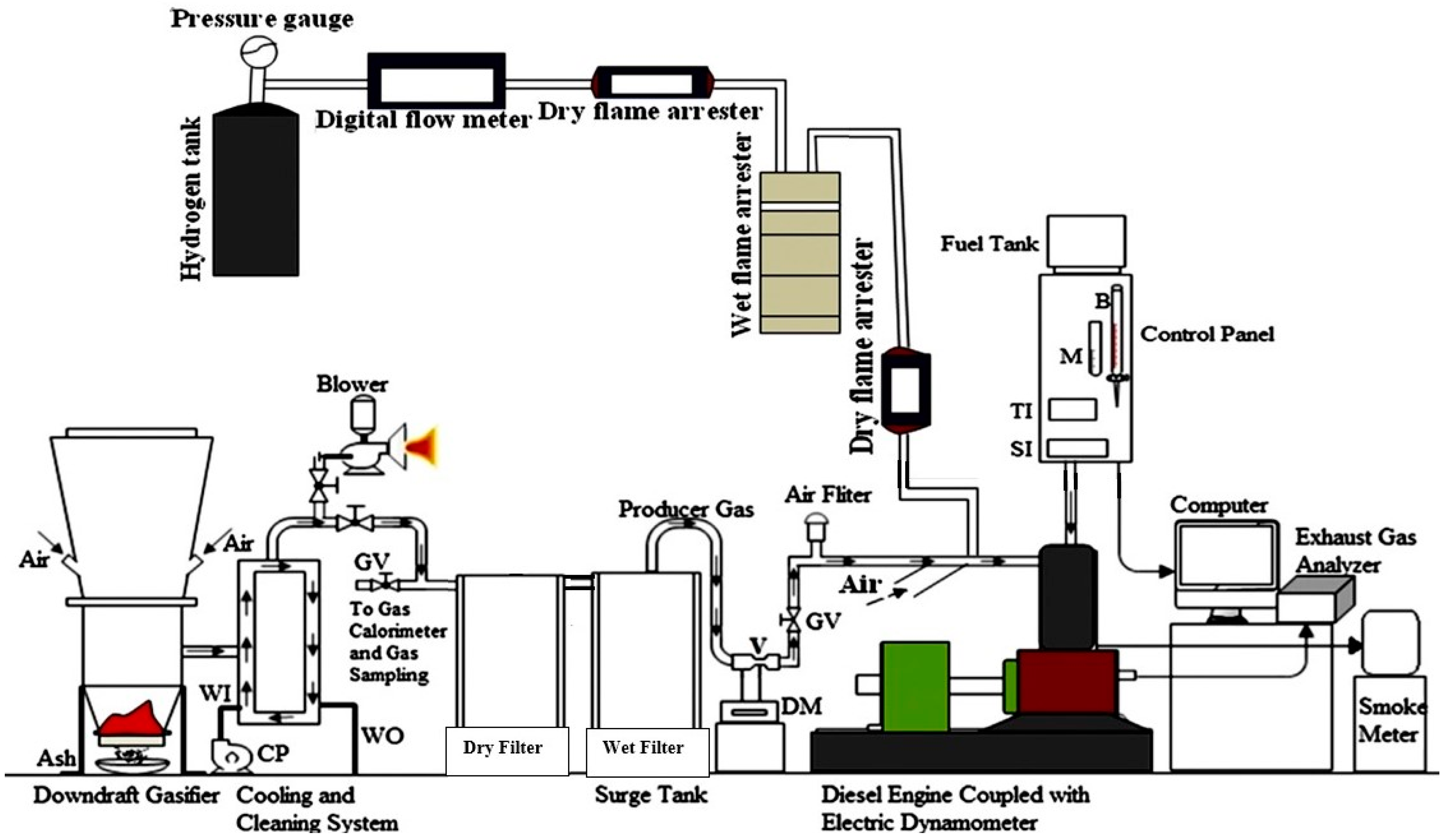
A suitably modified DF engine made from an existing single cylinder, four-stroke, water cooled, natural aspiration engine was used as shown in the Figure 1. Specification of engine used in this study is detailed in Table 4. Special arrangements were made for the induction of gaseous fuels as shown in Figure 1. The compression ignition (CI) engine was integrated with downdraft gasifier, along with different accessories such as air filters and with wet and dry filters for addressing the tar issues of the producer gas. Engine was operated at a constant speed of 1500 rpm. A 6-hole nozzle with a 0.2-mm diameter orifice size was used for pilot fuel injection using a conventional mechanical fuel injection system with a maximum injection pressure of 260 bar. The engine maker specified the IT as 23obTDC, IOP as 205 bar, and the compression ratio as 15.7, respectively. To achieve improved engine performance, these were optimized for the combined use of biodiesel, producer gas, and hydrogen gaseous fuels. Eventually, the optimal values of the 240 bar injection pressure, 17.5 CR, and 27obTDC IT were determined for experimentation. A suitable mixing chamber was employed for the homogeneous mixing of air and PG–hydrogen mixtures for the engine input. The engine’s tailpipe emissions were monitored once it reached steady state. Hydrogen gas stored in cylinder at a pressure of 150 bar was let into the injector by reducing its pressure to 1 bar using a pressure regulator and was then allowed to pass through a non-return valve. A flow meter was used to measure the flow rate of Hydrogen gas. This was further combined with an air-producing gas mixture by injecting the hydrogen into the inlet manifold of the engine.
For the safety aspects of engine operation, dry and wet flame arresters were utilized in the hydrogen lines. The flame arrester acts as non-return valves and prevents the back flow of the hydrogen flame reaching the gas cylinder. Initially, experiments were performed using single fuels of diesel, biodiesel, and its B20 blend for baseline data generation. Later, experiments were performed in DF engine modes using producer gas and hydrogen along with the selected pilot fuel of biodiesel injection.

2.2.2. Experimentation

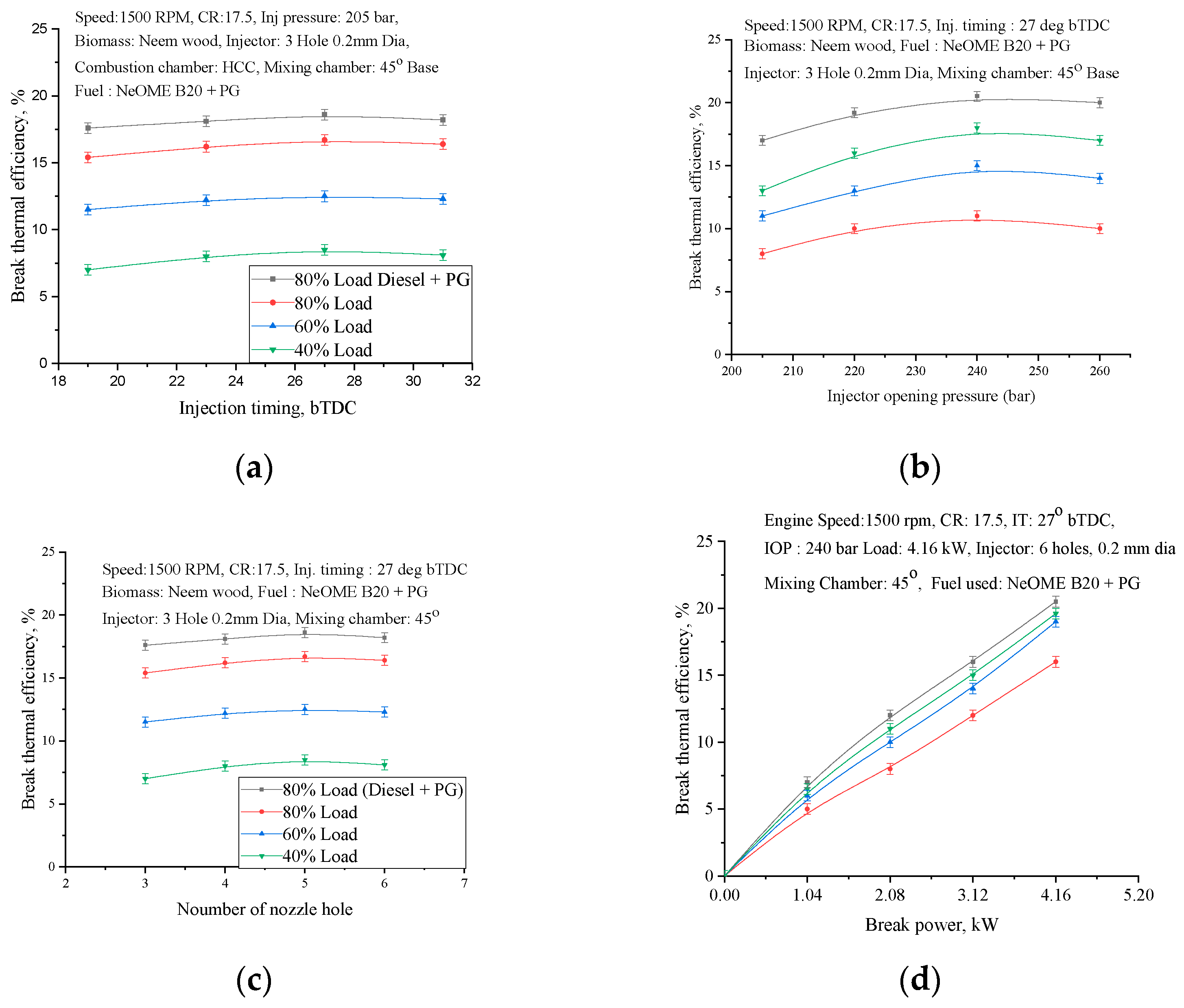
The DF engine test rig is designed to accommodate three fuel combinations of NeOME biodiesel, producer gas, and hydrogen, respectively. NeOME biodiesel was injected at an optimized injector opening pressure (IOP) of 240 bar and at an advanced IT of 27oBTDC, and the gaseous fuels of the producer gas and hydrogen were inducted at varied flow rates using flow control valves. After advancing the fuel IT from 19 to 27oBTDC, DF engine performance initially improved and then (31oBTDC) deteriorated, as shown in Figure 2a. BTE at 27oBTDC increased due to an increased delay period as time available for the air–fuel mixing increased. Similarly, as the IOP of NeOME increased from 200 to 240 bar, the BTE improved while emissions reduced, beyond which (260 bar) the engine performnce deteriorated, as shown in Figure 2b. This is due to the improved atomization of the NeOME biodiesel at 240 bar and the resulting uniform air–fuel mixture. Further, a 6-hole injector and a compatible and Lateral Dual Swirl combustion chamber (LDSCC) was used to further optimize the DF engine performance, as shown in Figure 2c,d respectively. All optimized parameters of IT (27oBTDC), IOP (240 bar), the number of injector holes (6), the and combustion chamber (LDSCC) were maintained as constant to facilitate further experimentation on the DF engine’s performance.
With the above optimized engine parameters, exhaustive engine experiments were conducted on the DF engine, in which the pilot fuel of the NeOME B20 flow rate varied from 0.4 to 0.8 kg/hr. The gaseous fuels of the producer gas and hydrogen varied from 7to 9 kg/h and 0.029 to 0.059 kg/h, respectively. The higher calorific value of carbon-free hydrogen gas enhanced the performance of the dual engine fuel when used along with producer gas induction.

2.3. Uncertainty Estimation

Table 5 shows the magnitudes of uncertainty in the measurement of the different parameters of the experimental studies.

2.4. Design of Experiments

The DOEs technique enables one to study the performance of a DF engine regarding the influence of different variables simultaneously. The DOEs technique aids in reducing the number of experimental tests to be conducted while maximizing time efficiency and minimizing fuel material use [21,22,23].
Three parameters—the flow rates of the NeOME B20, PG, and H2 fuels —are taken into consideration in the current work, and the ranges of these flow rates are chosen based on preliminary engine studies. Table 6 shows the flow parameters of liquid and gaseous fuels, respectively. Table 7 represents the design of the experimental plan adopted in the work.
Proper planning of the experiments is required for the generation of regression models using experimental data. The simplest experimental design for collecting observations is the full factorial design (FFD). In the present study, the flow rates of the NeOME B20, PG, and H2 fuels are considered as controlling factors, with three levels defined for each of the factors, as shown in Table 7. Thus, with k = 3 and l = 3, the minimum number of trials is Nmin = lk = 27 for full factorial design. Accordingly, 27 experiments were conducted, and the experimental results were recorded. These experimental results were further used to develop the mathematical models using regression analysis. The models developed were then used to analyze the interaction effects of the process parameters on the proposed performance measures [24,25].

2.5. Response Surface Modeling

With corresponding input variables, the empirical mathematical modeling of responses is fitted. Equation (1) specifies the quadratic model based on RSM [23].
z = C o + i = 1 k C i X i + C i i X i 2 + i < j = 2 C i j X i X j
The surface Z, which includes linear, nonlinear, and Xi’s interactions, is represented by Equation (1), where
Co = Coefficient and is a constant,
Ci = Coefficient which includes all linear terms,
Cii = Coefficient and are quadratic terms,
Cij = Coefficients are the interaction terms.
The regression model and coefficients are determined as per the literature [26]:
C = ( X T X ) 1 X T Z
where
X = Calculation matrix, which includes linear, quadratic and interaction terms.
The developed models obtained through multiple regression analysis are obtained using
XT = Transpose of X.
Z = the matrix of desired characteristic.
B T E = 25.76244 + 17.83333 A 3.69978 B + 326.60246 C 5.55555 A 2 + 0.14611 B 2 3439.50617 C 2 0.20833 A B 13.88889 A C 0.05555 B C
S m o k e = 40.97481 + 10 A 4.8 B 139.25926 0.33334 B 2 2962.96296 C 2 33.33334 B C
H C = 34.6092 + 74.7993 A + 11.65021 B 1527.68 C 33.3333 A 2 0.27627 B 2 + 17777.78 C 2 2.60926 A B 55.5556 A C 5.6534 B C
C O = 2.744683 3.83131 A 0.00016 B 29.9701 C + 1.805556 A 2 + 0.00036 B 2 + 320.9877 C 2 + 0.005572 A B + 0.277778 A C + 0.01486 B C
N O x = 152.7531 2.50685 A 1.96159 B + 986.2593 C + 8.333333 A 2 0.0141 B 2 12592.6 C 2 + 0.703957 A B + 111.1111 A C + 9.531057 B C
P max = 41.11426 + 10 A 0.00725 B + 620 C 0.0272 B 2 6666.67 C 2
I D = 35.62954 5 A + 0.003626 B 620 C + 0.01036 B 2 + 6666.667 C 2
C D = 81.37625 21.0237 A 0.31768 B 1582.99 C + 5.555556 A 2 + 0.033958 B 2 + 16543.21 C 2 + 0.010872 A B 55.5556 A C + 11.45176 B C
H R R = 11.20844 A + 25 B 4.13494 C + 3100 A 2 0.09065 C 2 33333.3 A B
In these Equations (3)–(11), NeOME B20 (A) is in kg/h, PG (B) is in kg/h, H2 (C) is in kg/h; BTE is in %; smoke is in HSU; HC is in ppm; CO in %, NOx is in ppm, Pmax is in bar, ID is in °CA, CD °CA, and heat release rate (HRR) is in J/°CA.
The Fisher (F) test [23] was utilized in the current study to assess the suitability of the fitted RSM-based models, and it was determined to be acceptable at a 1% impact level.
Table 8 presents an analysis of variance (ANOVA) summary [23].
Equation (12) provides the response surface model accuracy:
Δ = 100 n   i = 1 n | y i , exp t   y i , pred y i , pred |
where
  • yi,expt: Measured value of performance characteristic corresponding to ith trial.
  • yi,pred: RSM predicted value of performance characteristic corresponding to ith trial.
  • n: number of trials in FFD.
Using the experimental data provided in FFD, Equations (3)–(11) were developed to test the accuracy of the models.
Equations (3)–(11) are utilized to forecast the concerned characteristic by replacing the effects of the flow rates of three fuels, namely, NeOME B20 (pilot fuel), PG (induction), and H2 (injection), within the ranges of the stated parameters.

3. Results and Discussions

This section covers the overall performance of the DF engine when operating at various flow rates of the chosen fuel combinations.

3.1. Influence of Fuel Flow Rate on the Performance of DF Engine

Figure 3 illustrates the influence of fuel flow rates on the BTE of DF engines operating from 60 to 80% load. From Figure 3a, it follows that BTE increases with an increase in the load, as more of the pilot fuel NeOME B20 is injected inside the engine cylinder along with different flow rates of hydrogen [27,28].
A higher hydrogen flow rate leads to improved BTE for the same flow rates of PG. However, the BTE drops with a rise in PG flow rate at a fixed hydrogen addition, as shown in Figure 3b,c. This might be because the producing gas burns more slowly than hydrogen and has a lower calorific value.
For the same quantity of the injected NeOME B20 and producer gas, increasing hydrogen percentage increases the BTE of the DF engine. This could be because of the hydrogen’s larger calorific value, which is almost 3.25 times that of NeOME B20 and 25 times that of PG [29].
BTE increases with the increasing hydrogen flow rate from 0.029 to 0.046 kg/h for the same injected pilot fuel of NeOME B20. This is because of the hydrogen fuel’s higher calorific valve and faster flame velocity. The further addition of hydrogen (over 0.046 kg/h) reduces the BTE of the DF engine, causing severe engine knocking.
For the same pilot fuel flow rate, the BTE declines as the concentration of PG increases from 7 to 9 kg/h, as shown in Figure 3b. This is because of the lower calorific valve and poorer flame velocity of PG. An increase in the PG concentration decreases the quantity of air inducted into the engine and is the main cause for these trends [30,31].
Figure 3c clearly indicates that the BTE of the DF engine is affected by the gaseous flow rates of hydrogen and PG, respectively. Increasing the hydrogen flow rate until 0.046 kg/h assists in increasing the BTE, while an increase in PG results in a decrease in BTE values. Hence, the combined optimized flow rates of NeOME B20, hydrogen, and PG greatly affects the BTE of the DF engine.
BTE results from using the RSM technique were validated using experimental data at selected flow rates of biodiesel and gaseous fuels from the DF engine’s operation, as shown in Figure 3. Experimental and RSM results were in good agreement. The same trend was observed for all the test runs conducted, with correlation coefficient R2 as 0.9986, and showed good approximation.
For the optimized combination of the flow rates of NeOME B20 0.8 kg/h, hydrogen 0.044 kg/h, and PG 7 kg/h, the maximum BTE of the DF engine operation is found to be 23.75%.

3.2. Emission Characteristics

3.2.1. Influence of Fuel Flow Rate on the Smoke Emission

Figure 4 illustrates the influence of fuel flow rates on the smoke behavior of a DF engine operating from 60 to 80% load. From Figure 4a, it follows that smoke rises with an increase in the load, as more pilot fuel NeOME B20 is injected inside the engine cylinder along with different flow rates of hydrogen.
A higher hydrogen flow rate leads to decreased smoke opacity for the same flow rates of PG. However, the smoke increases with an increase in the PG flow rate for a fixed hydrogen percentage, as presented in Figure 4b,c.
From Figure 4a, it was found that, as the biodiesel flow rate increases, smoke rises. The addition of hydrogen to PG reduces the smoke level of the engine. Due to hydrogen’s ability to operate as a soot barrier and its clean burning characteristics, adding hydrogen to a gas-fueled engine reduces smoke emissions. In essence, hydrogen increases the H/C ratio by dehydrating the HC fuel. Therefore, the main benefits of a hydrogen addition are a decrease in soot nucleation and a decrease in smoke particles. Additionally, the reaction occurs because there are too many OH radicals [12]. Therefore, there is a decrease in smoke emission levels. Since H2 is a carbon-free gaseous fuel, it has a broader flammability limit and a higher flame velocity as well as zero tendencies to produce smoke.
For the same flow rates of NeOMEB20, as the PG flow rate increases, smoke increases. The sluggish burning of PG is the main cause for amplified smoke levels, as shown in Figure 4b,c.
When an engine runs at a higher PG flow rate, some of the oxygen is replaced by gaseous fuels. This reduces the amount of oxygen available for burning, which raises the level of smoke.
Lower smoke opacity was observed at a flow rate of NeOME B20 0.8 kg/h, hydrogen 0.044 kg/h, and PG 7 kg/h. The correlation coefficient (R2) between the predicted experimental and RSM outcomes was found to be 0.9985, indicating that the correlation was accurate.

3.2.2. Influence of Fuel Flow Rate on the HC and CO Emission

Figure 5 and Figure 6 show the HC and CO emissions for the flow rates of the fuels used.
From Figure 5a and Figure 6a, HC and CO levels reduced as the hydrogen flow rate increased. The fuel mixture burns more efficiently due to the higher heat release rate and faster flame velocity of hydrogen gas. Additionally, the addition of hydrogen can prolong the flammability of fuel, improving the combustion of fuel mixes. The addition of hydrogen raises the concentration of OH, H, and O radicals, which in turn accelerates reaction rates, improving combustion efficiency and lean burn mixture stability [32].
From Figure 5b and Figure 6b, for the same flow rate of NeOME B20, as the PG flow rate increases, an increase in HC and CO emissions was observed. Reduced air intake and the presence of CO in PG are also contributing factors in the above trends.
Further, from Figure 5c and Figure 6c, for the same flow rate of PG, as the hydrogen flow rate increases, a reduction in HC and CO was observed.
The minimum HC and CO was obtained for a hydrogen flow rate of 0.059 kg/h. The correlation between the projected experimental and RSM results was found to be accurate, and the correlation coefficient (R2) was found to be 0.9985.

3.2.3. Effect of Fuel Flow Rate on the NOx Emission

Figure 7 presents the disparities of NOx emission with different fuel flow rates. Figure 7a, shows that increasing the flow rate of biodiesel (NeOME B20) increases the NOx level. This is due to the fact that injecting more pilot gasoline into the engine cylinder raises both peak pressure and the heat release rate associated with higher in-cylinder temperature. With an elevated temperature, oxygen availability and residual time NOx increases. Furthermore, it should be noted that the injection of hydrogen raises NOx levels due to the elevated premixed combustion and engine cylinder combustion temperatures. Additionally, this can be the cause of higher NOx emissions. Because hydrogen burns more quickly and efficiently and has a higher calorific value, NOx levels in the exhaust increase as the H2 flow rates increase [33].
From Figure 7b, for the same flow rate of NeOME B20, as the PG flow rate increases, a lower NOx emission was observed. PG properties are responsible for this trend. In addition, the slower burning characteristics and lower flame velocity of PG also contributed to decreased NOx emissions.
From the Figure 7c, it was discovered that, as the PG flow rate increased, the NOx emission decreased. The minimum NOx was observed at a flow rate of 0.4 kg/h, 9 kg/h, and 0.059 kg/h for NeOME B20, PG, and H2, respectively. The experimental results and those predicted using the RSM are correlated, and the correlation coefficient (R2) was found to be 0.9974.

3.3. Combustion Characteristics

3.3.1. Influence of Fuel Flow Rate on the Peak Pressure

Figure 8 presents the disparities of peak pressure with fuel flow rates at 80% load. Figure 8a shows that increasing the flow rate of biodiesel (NeOMEB20) increases peak pressure. The maximum pressure attainment is dependent on how much pilot fuel is used during the uncontrolled or rapid combustion phase. Furthermore, higher peak pressure is attained for a given flow rate of NeOME B20 when the hydrogen flow rate increases.
From Figure 8b, peak pressure was found to decrease for the same flow rate of NeOME B20 as the PG flow rate increased. A decrease in cylinder pressure was caused by the slow burning of the producer gas and insufficient air–fuel mixing rates.
Figure 8c, shows that, as the PG flow rate increases, a lower peak pressure is observed. For the same flow rate of PG, as the H2 flow rate increases, a rise in peak pressure is obtained.
The correlation coefficient (R2) was found to be 0.9996, indicating that the experimental results and those predicted by the RSM were consistent.

3.3.2. Influence of Fuel Flow Rate on the Ignition Delay

Figure 9 presents the disparities of the ignition delay with different fuel flow rates. Figure 9a shows that increasing the flow rate of biodiesel NeOMEB20 reduces the ignition delay. Better air and hydrogen mixing brought about a reduction in ignition delay as the hydrogen flow rate increased during the DF engine mode [34].
From Figure 9b, the ignition delay increased as the PG flow rate increased for the same flow rate of NeOME B20. A lower cetane number and oxygen content in blended fuels cause variations in the air–fuel ratio and improper fuel mixing. Hence, these are responsible for the obtained findings.
Figure 9c shows that, as the concentration of PG increases, the ignition delay tends to increase. Moreover, the same decrease in the PG flow rate during the delay period was observed for the addition of hydrogen.
The correlation coefficient (R2) between the predicted experimental and RSM outcomes was found to be 1.000, indicating that the correlation was accurate.

3.3.3. Effect of Fuel Flow Rate on the Combustion Duration

Figure 10 presents the disparities of the combustion duration with a fuel flow rate at a different load. From Figure 10a, it is perceived that an increase in the flow rate of biodiesel (NeOMEB20) results in an enhanced combustion duration. This is mostly determined by the amount of fuel injected and the quality of combustion present inside the engine cylinder. During DF engine operation, a higher hydrogen flow rate led to shorter combustion times. This is because hydrogen makes PG and NeOME B20 burn more intensely [35].
As shown in Figure 10b, as the PG flow rate increases, there was an increment in the combustion duration observed for the same flow rate of NeOME B20.
Figure 10c shows that, as the concentration of PG increases in the fuel combination used, the combustion duration tends to increase. Further, for the same PG flow rate, a decrease in the combustion duration was observed for the hydrogen addition to PG.
The correlation coefficient (R2) was found to be 0.9923, indicating that the experimental results and those predicted using the RSM were consistent.

3.3.4. Effect of Fuel Flow Rate on the Heat Release Rate

Figure 11 presents the disparities of the HRR with the fuel flow rate. Figure 11a shows that an increase in the flow rate of biodiesel NeOMEB20 enhances the heat release rate. HRR increased for the same flow rate of NeOME B20 when the hydrogen flow rate increased. This might be because better fuel mixing with hydrogen results in better oxygen availability during combustion. Combustion with hydrogen produces an increased rate of heat release because of the higher flame velocity and higher energy content of hydrogen. To maintain the pressure rise during expansion in the DF operation, a part of pilot liquid fuel was also injected. However, because of the hydrogen, the fuel amalgamation’s flame accelerates more quickly, increasing the rate at which heat is released. This fact might offer the ideal chance to create a maximum pressure that will result in improved BTE [36].
As shown in Figure 11b, for the same flow rate of NeOME B20, as the PG flow rate increases, a decrease in the heat release rate is obtained, and this could be due to maximum air being replaced by PG.
Figure 11c shows that, as the concentration of PG rises, the HRR tends to decrease. Further, for the same PG flow rate, an increase in heat release rate was observed for the hydrogen addition. The relationship between the predicted experimental and RSM outcomes was determined to be a perfect match, with an R2 correlation coefficient of 0.9996.

3.3.5. Effect of Hydrogen Fuel Flow Rate on HRR

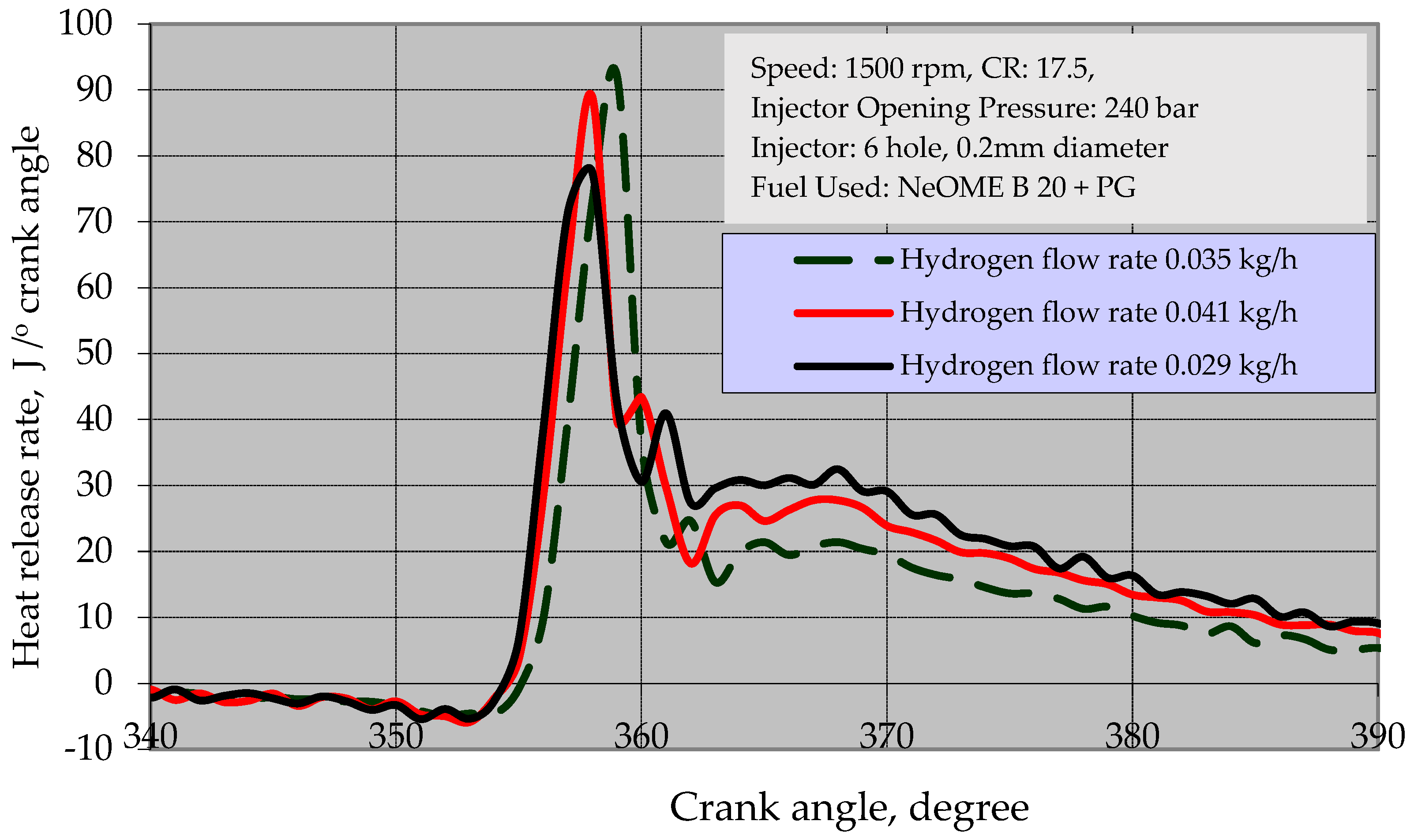
Figure 12 displays the variation of heat transfer rate for NeOME B20, PG, and H2 operated on a DF engine for three hydrogen flow rates, i.e., 0.029 kg/h, 0.035 kg/h, and 0.041 kg/h, respectively. According to the figure, a higher hydrogen flow rate improves the HRR, which raises the brake thermal efficiency. This might be the result of enhanced fuel mixing with hydrogen, which would improve oxidation with available oxygen. Using the energy content of H2 and the higher flame velocity of the fuel amalgamation during hydrogen combustion, HRR is improved. The partial burning of the fuel aggregation brought on by the lean mixture and oxygen shortage causes HRR to decrease at greater hydrogen flow rates beyond 0.041 kg/h.

3.3.6. Effect of Hydrogen Fuel Flow Rate on In-Cylinder Pressure

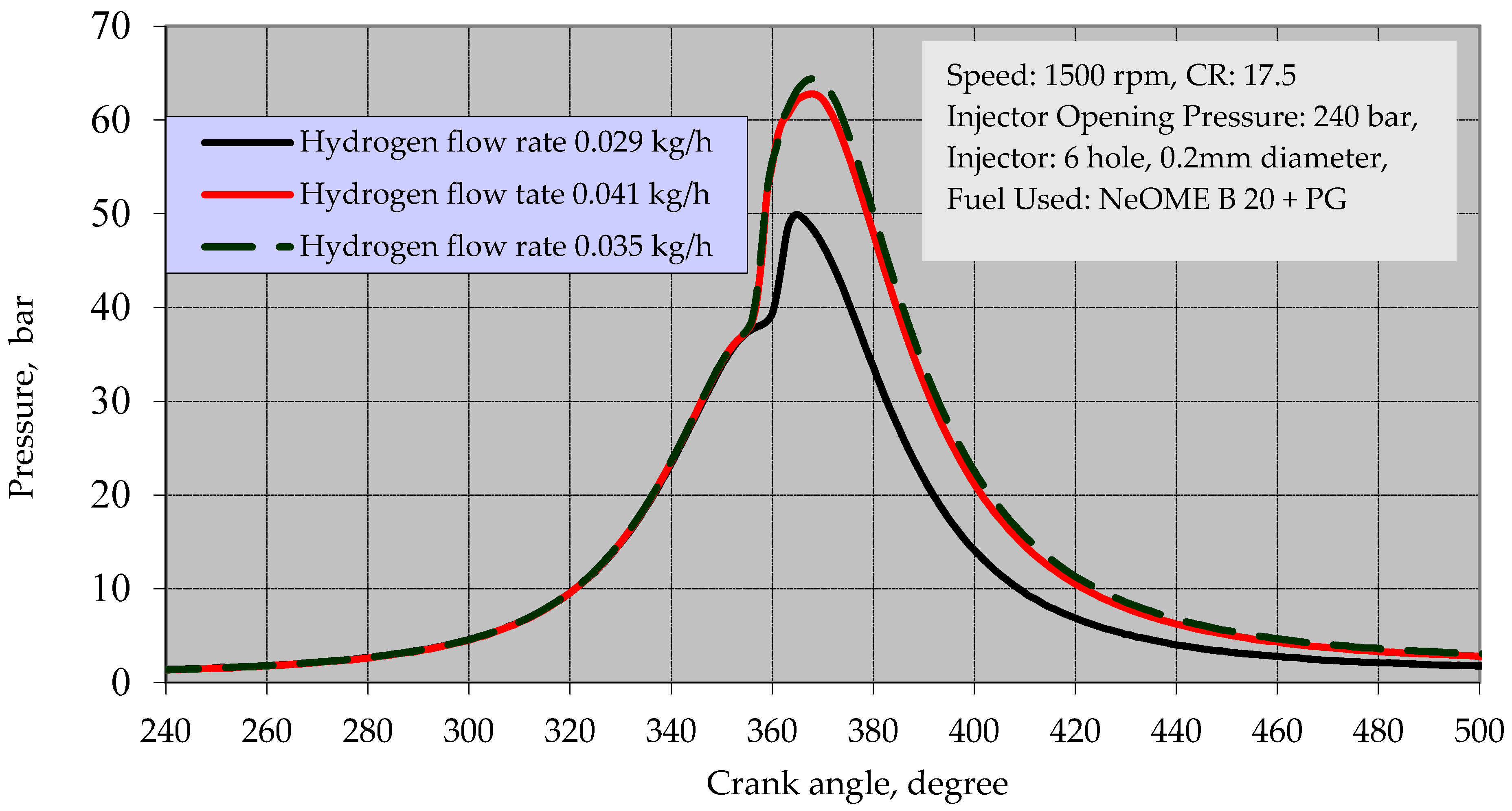
Figure 13 presents the variation of in-cylinder pressure of NeOME B20, PG, and H2 when operating on a DF engine for hydrogen flow rates i.e., 0.029 kg/h, 0.035 kg/h, and 0.041 kg/h, respectively. It was found that a higher hydrogen flow rate resulted in higher cylinder pressure. This may be because increased HRR results from the quick burning of the NeOME–PG mixture and from the autoignition of hydrogen, which ignites hydrogen and causes rapid combustion. Therefore, the increases in in-cylinder peak pressure and temperature are influenced by the enhanced combustion of the fuel mixtures. However, when the hydrogen flow rate was exceeded, a detrimental effect was noted. The observed patterns may be explained by lean mixture and mixture inhomogeneity.

4. Conclusions

In the current study, RSM was used to analyze the impacts of the fuel flow rate on the engine performance, emission, and combustion characteristics of biodiesel, PG, and hydrogen. This study is innovative in that it optimizes the fuel flow rate of a DF engine using RSM’s NeOME B20-PG+H2 fuel mixes. Biodiesel, PG, and hydrogen flow rates were chosen for the RSM as input factors, and BTE, smoke, HC, CO, NOx, Pmax, ID, Cd, and HRR were chosen as the output parameters. With confidence levels of 95%, all statistical models created by RSM from test data for the performance and emission attributes were found to be significant. R2 values were determined to be 0.9986, 0.9985, 0.9985, 1.000, 0.9974, 1.000, 0.9923, 0.9895, and 0.9996 for BTE, smoke, HC, CO, NOx, Pmax, ID, and HRR, respectively. According to the RSM results, the best engine operating factors for the biodiesel, PG, and hydrogen fuel flow rates were discovered to be 0.8, 7, and 0.044 kg/h, with the best responses being 23.75%, 30 HSU, 32 ppm, 0.31%, 225 ppm, 61 bar, 16°CA, 28°CA, and 78 J/°CA for BTE, smoke, HC, CO, NOx, Pmax, ID, Cd, respectively.
The DF technology is well established and can accommodate different fuels simultaneously. The limitation of the work reported refers to use of lower injection pressures of pilot fuel quantity. This can be suitably overcome by adopting an electronic control unit (ECU)-enabled, high-pressure injection system with a common rail direct injection facility (CRDI). In this facility, typical injection pressures ranged from 600 to 1200 bar.
Author Contributions

Conceptualization, S.S.H., N.R.B. and V.S.Y.; methodology, S.S.H. and N.R.B.; software, V.N.G.; validation, V.N.G. and N.R.B.; investigation, S.S.H. and N.R.B.; resources, C.V. and S.K.; data curation, A.M.S.; writing—original draft preparation, S.S.H. and N.R.B.; review and editing, N.R.B., V.S.Y. and V.N.G.; supervision, N.R.B. and V.S.Y.; research supporting and facilities, N.R.B.; project administration, N.R.B., C.V. and S.K.; funding acquisition, T.M.Y.K., C.V. and S.K. All authors have read and agreed to the published version of the manuscript.

Funding

This work was funded by King Khalid University and the Ministry of Education in KSA under the Grant number R.G.P. 2/76/44.

Institutional Review Board Statement

Not applicable.

Informed Consent Statement

Not applicable.

Data Availability Statement

Not applicable.

Acknowledgments

The authors extend his appreciation to the Deanship of Scientific Research at King Khalid University for funding this work through research groups program R.G.P. 2/76/44.

Conflicts of Interest

The authors declare no conflict of interest.

References

  1. Hosmath, R.S.; Banapurmath, N.; Khandal, S.V.; Gaitonde, V.N.; Basavarajappa, Y.H.; Yaliwal, V.S. Effect of compression ratio, CNG flow rate and injection timing on the performance of DF engine operated on honge oil methyl ester (HOME) and compressed natural gas (CNG). Renew. Energy 2016, 93, 579–590. [Google Scholar] [CrossRef]
  2. Banapurmath, N.R.; Tewari, P.G.; Hosmath, R.S. Effect of biodiesel derived from Honge oil and its blends with diesel when directly injected at different injection pressures and injection timings in single-cylinder water-cooled compression ignition engine. Proc. Inst. Mech. Eng. Part A J. Power Energy 2008, 223, 31–40. [Google Scholar] [CrossRef]
  3. Banapurmath, N.R.; Tewari, P.G. Comparative performance studies of a 4-stroke CI engine operated on dual fuel mode with producer gas and Honge oil and its mythyl ester (HOME) with and without carburetor. Renew. Energy 2009, 34, 1009–1015. [Google Scholar] [CrossRef]
  4. Geo, V.E.; Nagarajan, G.; Nagalingam, B. Experimental Investigations to Improve the Performance of Rubber Seed Oil–Fueled Diesel Engine by Dual Fueling with Hydrogen. Int. J. Green Energy 2009, 6, 343–358. [Google Scholar] [CrossRef]
  5. Deshmukh, S.J.; Bhuyar, L.B.; Thakre, S.B. Investigation on Performance and Emission Characteristics of CI Engine Fuelled with Producer Gas and Esters of Hingan (Balanites) Oil in Dual Fuel Mode. Int. J. Aerosp. Mech. Eng. 2008, 27, 148–153. [Google Scholar]
  6. Udaya Sri, K.; Murthy, B.S.N.; Mohan Rao, N. Monitoring Exhaust Emissions of A Direct Injection Diesel Engine Fueled with Linseed Oil Biodiesel—Hydrogen Dual Fuel Energy. Int. J. Innov. Technol. Explor. Eng. 2021, 10, 42–49. [Google Scholar]
  7. Singh, R.N.; Singh, S.P.; Pathak, B.S. Investigations on operation of CI engine using producer gas and rice bran oil in mixed fuel mode. Renew. Energy 2007, 32, 1565–1580. [Google Scholar] [CrossRef]
  8. Sayin, C.; Gumus, M. Impact of compression ratio and injection parameters on the performance and emissions of a DI diesel engine fueled with biodiesel-blended diesel fuel. Appl. Therm. Eng. 2011, 31, 3182–3188. [Google Scholar] [CrossRef]
  9. Yaliwal, V.S.; Nataraja, K.; Banapurmath, N.; Tewari, P. Honge oil methyl ester and producer gas-fuelled dual-fuel engine operated with varying compression ratios. Int. J. Sustain. Eng. 2013, 7, 330–340. [Google Scholar] [CrossRef]
  10. Banapurmath, N.R.; Tewari, P.G.; Yaliwal, V.S.; Kambalimath, S.; Basavarajappa, Y.H. Combustion characteristics of a 4-stroke CI engine operated on Honge oil, Neem and Rice Bran oils when directly injected and dual fuelled with producer gas induction. Renew. Energy 2009, 34, 1877–1884. [Google Scholar] [CrossRef]
  11. Yaliwal, V.S.; Banapurmath, N.R. Combustion and emission characteristics of a compression ignition engine operated on dual fuel mode using renewable and sustainable fuel combinations. SN Appl. Sci. 2021, 3, 24. [Google Scholar] [CrossRef]
  12. Kashyap, D.; Das, S.; Kalita, P. Exploring the efficiency and pollutant emission of a dual fuel CI engine using biodiesel and producer gas: An optimization approach using response surface methodology. Sci. Total Environ. 2021, 773, 145633. [Google Scholar] [CrossRef] [PubMed]
  13. Khoobbakht, G.; Najafi, G.; Karimi, M.; Akram, A. Optimization of operating factors and blended levels of diesel, bio-diesel and ethanol fuels to minimize exhaust emissions of diesel engine using response surface methodology. Appl. Therm. Eng. 2016, 99, 1006–1017. [Google Scholar] [CrossRef]
  14. Najafi, G.; Ghobadian, B.; Yusaf, T.; Ardebili, S.M.S.; Mamat, R. Optimization of performance and exhaust emission parameters of a SI (spark ignition) engine with gasoline–ethanol blended fuels using response surface methodology. Energy 2015, 90, 1815–1829. [Google Scholar] [CrossRef]
  15. Dhole, A.E.; Yarasu, R.B.; Lata, D.B.; Baraskar, S.S.; Shaw, D. Mathematical modeling for the performance and emission parameters of dual-fuel diesel engine using producer gas as secondary fuel. Biomass Convers. Bioref. 2015, 5, 257–270. [Google Scholar] [CrossRef]
  16. Hirkude, J.B.; Padalkar, A.S. Performance optimization of CI e fuelled with waste fried oil methyl ester-diesel blend using response surface methodology. Fuel 2014, 119, 266–273. [Google Scholar] [CrossRef]
  17. Pandian, M.; Sivapirakasam, S.P.; Udayakumar, M. Investigation on the effect of injection system parameters on performance and emission characteristics of a twin cylinder compression ignition direct injection engine fuelled with pongamia biodiesel–diesel blend using response surface methodology. Appl. Energy 2011, 88, 2663–2676. [Google Scholar] [CrossRef]
  18. Atmanlı, A.; Yüksel, B.; Ileri, E.; Karaoglan, A.D. Response surface methodology based optimization of diesel–n-butanol –cotton oil ternary blend ratios to improve engine performance and exhaust emission characteristics. Energy Convers. Manag. 2015, 90, 383–394. [Google Scholar] [CrossRef]
  19. Simsek, S.; Uslu, S. Determination of a diesel engine operating parameters powered with canola, safflower and waste vegetable oil based biodiesel combination using response surface methodology (RSM). Fuel 2020, 270, 117496. [Google Scholar] [CrossRef]
  20. Singh, Y.; Sharma, A.; Tiwari, S.; Singla, A. Optimization of diesel engine performance and emission parameters employing cassia tora methyl esters-response surface methodology approach. Energy 2019, 168, 909–918. [Google Scholar] [CrossRef]
  21. Sharma, A.; Ansari, N.A.; Pal, A.; Singh, Y.; Lalhriatpuia, S. Effect of biogas on the performance and emissions of diesel engine fuelled with biodiesel-ethanol blends through response surface methodology approach. Renew. Energy 2019, 141, 657–668. [Google Scholar] [CrossRef]
  22. Rith, M.; Gitano-Briggs, H.W.; Gonzaga, J.A.; Biona, J.B.M. Optimization of control factors for a diesel engine fueled with jatropha seed producer gas on dual fuel mode. Int. Energy J. 2019, 19, 149–158. [Google Scholar]
  23. Myers, R.H.; Montgomery, D.C.; Anderson-Cook, C.M. Response Surface Methodology; John Wiley & Sons, Inc.: Hoboken, NJ, USA, 2009. [Google Scholar]
  24. Liu, J.; Yang, F.; Wang, H.; Ouyang, M.; Hao, S. Effects of pilot fuel quantity on the emissions characteristics of a CNG/diesel dual fuel engine with optimized pilot injection timing. Appl. Energy 2013, 110, 201–206. [Google Scholar] [CrossRef]
  25. Sagari, J.K.; Sukhvinder Kaur, B.; Vadapalli, S.; Dadi, V.T.; Guddanti, S.S.; Lakkoju, S.K. Comprehensive performance, combustion, emission, and vibration parameters assessment of diesel en-gine fuelled with a hybrid of niger seed oil biodiesel and hydrogen: Response surface methodology approach. SN Appl. Sci. 2020, 2, 1508. [Google Scholar] [CrossRef]
  26. Sezer, İ. Thermodynamic, performance and emission investigation of a diesel engine running on dimethyl ether and diethyl ether. Int. J. Therm. Sci. 2011, 50, 1597–1603. [Google Scholar] [CrossRef]
  27. Sathishkumar, G.B.; Thillaigovindarajan, B. Performance and Emission Characteristics of C.I Engine fuelled with Pungamia Methyl Ester and it’s Blended with Diesel. Int. J. Curr. Res. Dev. 2017, 5, 47–55. [Google Scholar]
  28. Raheman, H.; Padhee, D. Combustion characteristics of diesel engine using producer gas and blends of Jatropha methyl ester with diesel in mixed fuel mode. Int. J. Renew. Energy Dev. 2014, 3, 228–235. [Google Scholar] [CrossRef] [Green Version]
  29. Muralidharan, K.; Vasudevan, D. Performance, emission and combustion characteristics of a variable compression ratio engine using methyl esters of waste cooking oil and diesel blends. Appl. Energy 2011, 88, 3959–3968. [Google Scholar] [CrossRef]
  30. Halewadimath, S.S.; Yaliwal, V.S.; Banapurmath, N.R.; Sajjan, A.M. Influence of hydrogen enriched producer gas (HPG) on the combustion characteristics of a CRDI diesel engine operated on dual-fuel mode using renewable and sustainable fuels. Fuel 2020, 270, 117575. [Google Scholar] [CrossRef]
  31. Yaliwal, V.S.; Banapurmath, N.R.; Gaitonde, V.N.; Malipatil, M.D. Simultaneous optimization of multiple operating engine parameters of a biodiesel-producer gas operated compression ignition (CI) engine coupled with hydrogen using response surface methodology. Renew. Energy 2019, 139, 944–959. [Google Scholar] [CrossRef]
  32. Ramakrishnan, P.; Kasimani, R.; Peer, M.S. Optimization in the performance and emission parameters of a DI diesel engine fuelled with pentanol added Calophyllum inophyllum/diesel blends using response surface methodology. Environ. Sci. Pollut. Res. 2018, 25, 29115–29128. [Google Scholar] [CrossRef] [PubMed]
  33. Di Blasio, G.; Viscardi, M.; Beatrice, C. DoE method for operating parameter optimization of a dual-fuel bioetha-nol/diesel light duty engine. J. Fuels 2015, 2015, 674705. [Google Scholar] [CrossRef] [Green Version]
  34. Durakovic, B. Design of experiments application, concepts, examples: State of the art. Period. Eng. Nat. Sci. 2017, 5, 421–439. [Google Scholar] [CrossRef]
  35. Roy, M.M.; Tomita, E.; Kawahara, N.; Harada, Y.; Sakane, A. Effect of fuel injection parameters on engine performance and emissions of a supercharged producer gas diesel dual fuel engine. Soc. Autom. Eng. 2009. [Google Scholar] [CrossRef]
  36. Tadveer, S.H.; Avinash, K.A. Effect of varying compression ratio on combustion, performance, and emissions of hydrogen enriched compressed natural gas fuelled engine. J. Nat. Gas Sci. Eng. 2016, 31, 819–828. [Google Scholar]
Figure 1. Detailed representation of experimental setup.
Sustainability 15 04483 g001
Figure 2. (a) Effect of injection timing on brake thermal efficiency. (b) Effect of injector opening pressure on brake thermal efficiency. (c) Effect of number of injector hole on brake thermal efficiency. (d) Effect of combustion chamber shapes on brake thermal efficiency.
Sustainability 15 04483 g002
Figure 3. (a) Effect of NeOME B20 and Hydrogen flow rate on the BTE. (b) Effect of NeOME B20 and PG flow rate on the BTE. (c) Effect of PG and Hydrogen flow rate on the BTE.
Sustainability 15 04483 g003
Figure 4. (a) Effect of NeOME B20 and Hydrogen flow rate on the Smoke opacity. (b) Effect of NeOME B20 and PG flow rate on the Smoke opacity. (c) Effect of PG and Hydrogen flow rate on the Smoke opacity.
Sustainability 15 04483 g004
Figure 5. (a) Effect of NeOME B20 and Hydrogen flow rate on Hydrocarbon emission. (b) Effect of NeOME B20 and PG flow rate on Hydrocarbon emission. (c) Effect of PG and Hydrogen flow rate on Hydrocarbon emission.
Sustainability 15 04483 g005
Figure 6. (a) Effect of NeOME B20 and Hydrogen flow rate on CO emission. (b) Effect of NeOME B20 and PG flow rate on CO emission. (c) Effect of PG and Hydrogen flow rate on CO emission.
Sustainability 15 04483 g006
Figure 7. (a) Effect of NeOME B20 and Hydrogen flow rate on NOx emission. (b) Effect of NeOME B20 and PG flow rate on NOx emission. (c) Effect of PG and Hydrogen flow rate on NOx emission.
Sustainability 15 04483 g007
Figure 8. (a) Effect of NeOME B20 and Hydrogen flow rate on peak pressure. (b) Effect of NeOME B20 and PG flow rate on peak pressure. (c) Effect of PG and Hydrogen flow rate on peak pressure.
Sustainability 15 04483 g008
Figure 9. (a) Effect of NeOME B20 and Hydrogen flow rate on ignition delay. (b) Effect of NeOME B20 and PG flow rate on ignition delay. (c) Effect of PG and Hydrogen flow rate on ignition delay.
Sustainability 15 04483 g009
Figure 10. (a) Effect of NeOME B20 and Hydrogen flow rate on combustion duration. (b) Effect of NeOME B20 and PG flow rate on combustion duration. (c) Effect of PG and Hydrogen flow rate on combustion duration.
Sustainability 15 04483 g010
Figure 11. (a) Effect of NeOME B20 and Hydrogen flow rate on HRR. (b) Effect of NeOME B20 and PG flow rate on HRR. (c) Effect of PG and Hydrogen flow rate on HRR.
Sustainability 15 04483 g011
Figure 12. Effect of hydrogen fuel flow rate on HRR.
Sustainability 15 04483 g012
Figure 13. Effect of fuel flow rate on in-cylinder pressure.
Sustainability 15 04483 g013
Table 1. Biomass feedstock Properties.
Properties of BiomassMixture of BiomassStandardProperties of BiomassProducer Gas Composition
Moisrure (w/w%)10.98 ASTM D3173Carbon Monoxide, %14–18
Residue substance (w/w)0.89ASTM D 3042Hydrogen, %17–20
Capricious substance (%w/w)75--CH4, %0.9–5.9
CO (w/w %)11.7ASTM D3178Hydro Carbon, % 0.2–0.3
S2 (w/w %)0.1ASTM D5453Nitrogen, %30.9–40.9
N2 (w/w %)0.17ASTM D3179Water vapor, %5
CV (kJ/kg)18,861ASTM D240Carbon Dioxide, %8–11
Density (kg/m3)270–280ASTM D287CV of PG from Neem wood, MJ/m35–5.6
Table 2. Properties of liquid fuels.
PropertiesDieselNeem OilNeOMEB20Standard
Fire point, °C68253167ASTM D92
Kinematic viscosity @ 40 °C, mm2/s3.1241.14.7ASTM D445
Flash point, °C56237153ASTM D93
Density, @40 °C, kg/m3830863825ASTM D287
CV, kJ/kg43,50039,86642,501ASTM D240
Cetane number5459---ASTM D613
Residue of carbon, %0.210.730.084ASTM D189
Table 3. Properties of hydrogen gas.
Properties of HydrogenContent
Flame velocity, cm/s265–325
CV value, MJ/kg120.5
Density, g/L 0.0899
Boiling point, K250
The temperature of auto ignition, K858
Flammability limits in air, vol. %3.9–74
Flame velocity, cm/s351
Viscosity [μPas] (1 bar, 20 °C)8.79
Octane number131
Table 4. Experimental test rig specifications.
ParametersValues
Engine typeKirolskar model, TV1 CI engine, CC (661), CR (17.5:1), output Power (5.2 kW) at speed (1500 rpm)
Software usedEngine Soft
Nozzle opening pressure (NOP) 200–280 bar
Cylinder diameter0.0875 m
Stroke length0.11 m
Piston bowl geometry 52 mm diameter
Clearance of cylinder40.1 CC
Connecting rod length234 mm
Table 5. Uncertainty values.
Parameter Uncertainty in (%)
Load0.1
Engine speed1.0
Temperature1.0
Fuel consumption0.1
BTE±1.25
Exhaust gas temperature±2.1
HC±1.3
CO±2.65
NOx±2.45
Table 6. Engine parameters and its levels.
Parameter (Flow Rate kg/h)NotationLevels
BiodieselA0.40.60.8
PGB789
H2C0.0290.0440.059
Table 7. Experimental design plan and values of responses.
NeOME B20PGH2BTESmokeHCCONOxPmaxIDCDHRR
(kg/h)(kg/h)(kg/h)(%)(HSU)(ppm)(%)(ppm)(bar)(°CA)(°CA)(J/°CA)
0.470.02919.0128300.2218038203065
0.470.04420.2526280.2119543192968
0.470.05919.6123250.219041182866
0.480.02917.5329310.2417536213255
0.480.04418.5728300.2318540203059
0.480.05918.0325270.2218038192957
0.490.02916.2631330.2617035223450
0.490.04417.1530320.2518039213354
0.490.05916.6928300.2417537203252
0.670.02921.0130320.2719546183270
0.670.04422.2528300.2621051173173
0.670.05921.6125270.2520549163071
0.680.02919.5331330.2919044193460
0.680.04420.5730320.2820048183264
0.680.05920.0327290.2719546173162
0.690.02918.2633350.3118543203655
0.690.04419.1532340.319547193559
0.690.05918.6930320.2919045183457
0.870.02923.0132340.3221056173475
0.870.04423.7530320.3122561163378
0.870.05923.1127290.322059153276
0.880.02921.0333350.3420554183665
0.880.04422.0732340.3321558173469
0.880.05921.5329310.3221056163367
0.890.02919.7635370.3620053193860
0.890.04420.6534360.3521057183764
0.890.05920.1932340.3420555173662
Table 8. Summary of ANOVA and R2 values for developed models.
CharacteristicSum of SquaresDegrees of FreedomMean SquareF-RatioR2
RegressionResidualRegressionResidualRegressionResidual
BTE101.8100.14591711.31220.00851330.850.9986
Smoke222.3330.33391724.70370.01961260.390.9985
HC222.3330.33391724.70370.01961260.390.9985
CO0.0540.0019170.00600.00005120.001.000
NOx5502.80014.58917611.34000.858712.510.9974
Pmax1614.0800.580917179.34300.0345274.790.9996
ID78.0000.0019178.66670.000051733341.000
CD171.3331.33391719.03700.0784242.820.9923
HRR1464.080.580917162.67670.034114769.180.9996
Cost35100.001917390.0000.0000578000001.000
Disclaimer/Publisher’s Note: The statements, opinions and data contained in all publications are solely those of the individual author(s) and contributor(s) and not of MDPI and/or the editor(s). MDPI and/or the editor(s) disclaim responsibility for any injury to people or property resulting from any ideas, methods, instructions or products referred to in the content.