Article

Shear Strengthening of RC Beams Using Fabric-Reinforced Cementitious Matrix, Carbon Plates, and 3D-Printed Strips

1
Civil Engineering Department, The University of Jordan, Amman P.O. Box 11942, Jordan
2
Civil Engineering Department, Applied Science Private University, Amman P.O. Box 11931, Jordan
3
Civil Engineering Department, Faculty of Engineering, The Hashemite University, Zarqa P.O. Box 330127, Jordan
*
Author to whom correspondence should be addressed.
Sustainability 2023, 15(5), 4293; https://doi.org/10.3390/su15054293
Submission received: 7 January 2023 / Revised: 23 February 2023 / Accepted: 25 February 2023 / Published: 28 February 2023
(This article belongs to the Section Sustainable Materials)

Abstract

:
Existing reinforced concrete (RC) structures suffer from degradation in their structural capacity. These structures require strengthening and retrofitting to integrate sustainability and improve their serviceability and durability. RC members strengthened with fiber-reinforced polymer (FRP) composites usually suffer from FRP debonding; therefore, researchers proposed several types of sustainable materials to overcome the shortcomings of FRP composites. Limited experimental studies have been conducted for shear strengthening of RC beams using sustainable fabric-reinforced cementitious matrix (FRCM) composites; moreover, the application of 3D-printed strips in strengthening RC beams has never been established. The current research experimentally investigates the efficiency of FRCM composites, 3D-printed sheets (CD), and CFRP plates (CP) in strengthening RC beams that are weak in shear. Various strengthening configurations were adopted, including vertical, oblique, zigzag, and several-slanted layouts. Eight simply supported beams were prepared to find the most efficient shear-strengthening configuration and material for RC beams. Test results showed that FRCM and CP are both efficient for shear strengthening in terms of maximum load capacity, initial stiffness, and ductility. However, CD showed a limited effect on enhancing the performance of shear-strengthened beams. The best shear enhancement was found in the beam strengthened with vertical CP, with improvements in load-carrying capacity, stiffness, and ductility of 43%, 23%, and 23%, respectively. The vertical and oblique strengthening configurations were more efficient than the zigzag and several-slanted layouts. The ACI 440.2R-17 model yielded accurate predictions with an average (Vc, test/Vc, ACI 440) of 1.11.

1. Introduction

The rehabilitation of existing reinforced concrete structures has become essential, especially for cases where structural deterioration occurs due to increments in service loads, inadequate design, mistakes in construction, during earthquake events, etc. Several experimental studies [1,2,3,4,5] were conducted to strengthen existing RC structures in order to enhance their load-carrying capacities and ductility. Different materials were used to strengthen RC elements, such as fiber-reinforced polymers (FRP), fabric-reinforced cementitious matrix (FRCM), sustainable materials, natural base materials, metals, etc. FRP composites have commonly been used to strengthen RC structures due to their unique advantages, such as their light weight, corrosion resistance, high tensile strength, etc. By contrast, RC members strengthened with FRP composites usually suffer from FRP debonding, especially in humid regions. Therefore, researchers proposed other materials to overcome the shortcomings of FRP composites, such as fabric-reinforced cementitious matrix (FRCM) composites. FRCM composite consists of a fabric grid and a cementitious binder called a cementitious matrix. FRCM has superior properties to FRP in resisting fire attacks and humidity. FRCM is a relatively new material with various fabric grids, including glass, carbon, etc.
Limited experimental studies have been conducted to investigate the structural behavior of RC elements strengthened with FRCM composites. Wakjira and Ebead [6] used various types of FRCM composites to strengthen RC beams that are weak in shear. They found that FRCM increased the shear capacities of the beams by up to 62% with polyparaphenylene benzobisoxazole (PBO) FRCM, 83% with carbon FRCM, and 72% with glass FRCM. Younis et al. [7] showed that FRCM composites enhanced the shear capacity of RC beams by up to 51%, where the enhancement percentage significantly depends on the orientation of the grid fabric. Marcinczak et al. [8] found that PBO–FRCM composites increased the shear strength of RC beams in a range of 10–27%. They also found that slippage occurred between the grid and the cementitious matrix of the FRCM composites; hence, they suggested adequately anchoring the FRCM composites to avoid mesh debonding. Yang et al. [9] investigated the shear behavior of RC beams strengthened with FRCM composites, and they found that FRCM improved the shear capacities of the beams in a range of 51% to 161%, where the enhancement percentage depends on the type of FRP grid and the cementitious matrix. Murad [10] investigated the cyclic behavior of RC beam-to-column joints rehabilitated with FRCM composites. Murad showed that FRCM improved the ductility of the joint specimens by up to 166%, leading to changing of the failure mode from joint shear to a ductile desirable beam hinge. Murad also found that FRCM did not restore the strength capacity of the heat-damaged joint specimens.
Several experimental studies conducted by Haddad and Almasaeid [11], Mhanna et al. [12], Shomali et al. [13], Kotynia et al. [14], Al-Shamayleh et al. [15], Mohamed et al. [16], Askar et al. [17], Godat et al. [18], Al-Rousan [19], Mukhtar and Deifalla [20], Karayannis et al. [21], and Chalioris et al. [22] confirmed the efficiency of carbon FRP plates and laminates in enhancing the shear behavior of RC beams. Mohamed et al. [16] carried out an experimental program to study the shear behavior of RC beams strengthened with near-surface-mounted CFRP laminates. They found that CFRP plates improved the shear strength of RC beams by 112%. Shomali et al. [13] found that vertical CFRP plates enhanced the shear strength of RC beams with and without stirrups by up to 37% and 71%, respectively. They also found that the inclined CFRP plates (angle of 45°) improved the shear strength of RC beams with and without stirrups by 60% and 95%, respectively. Saadah et al. [23] showed that inclined CFRP plates increased the shear strength of RC beams in a range of 150–170% based on the spacing between the CFRP, and they also changed the mode of failure from a pure brittle shear to a combined flexural-shear failure. Three-dimensional (3D) printing technology has been recently applied in various sectors, such as medicine, dentistry, construction, etc. A limited number of RC buildings and bridges have been newly constructed with 3D printers that are able to print any material in any size and shape. This 3D-printing technology facilitates constructing and repairing complex structures with reduced time, effort, number of workers, and cost. One of the most popular printing methods is fused deposition modeling (FDM), which works by melting the material filaments in a heated nozzle and then printing the element layer by layer on a flat plate. Limited experimental studies were conducted with 3D-printed elements. Murad and Abu-Alhaj [24] used 3D-printed bars made from polylactic acid (PLA) and 20% carbon fibers to rehabilitate heat-damaged RC beams. They found that the 3D-printed bars improved the load-carrying capacity of the beams by 34%. Murad and AlSeid [25] found that 3D-printed bars made using polylactic acid (PLA) and 20% carbon enhanced the load-carrying capacity of RC beam-to-column joints by 51%.
Existing RC structures suffer from degradation in their structural capacity due to corrosion, carbonation, etc. These structures require strengthening and retrofitting to integrate sustainability and improve their serviceability and durability. The sustainability of RC members is a big concern in order to construct durable and strong RC structures. RC members strengthened with FRP composites usually suffer from FRP debonding; therefore, researchers proposed several types of sustainable materials to overcome the shortcomings of FRP composites. Aksoylu et al. [26] confirmed the efficiency of recycled steel wires from waste tires in enhancing the shear behavior of RC beams. Abdulhameed et al. [27] confirmed the efficiency of sustainable concrete modified with crumb rubber and oil palm fiber. Abdulhameed et al. [28] also confirmed the feasibility of using egg-shell powder and nano-limestone powder as a partial replacement for cement in the production of self-consolidating concrete.
Limited experimental studies have been conducted for shear strengthening of RC beams using sustainable FRCM composites and 3D-printed strips. Furthermore, the application of 3D-printed strips in strengthening RC beams has never been established in the literature. The current research experimentally investigates the efficiency of FRCM composites, 3D-printed sheets, and CFRP plates in strengthening RC beams that are weak in shear. Various strengthening configurations were applied to investigate the influence of the orientation of the strengthening composites on the shear behavior of RC beams. Analytical predictions were obtained using the ACI-440 [29] and then compared with the experimental test results to check the applicability of the code formulation for RC beams strengthened with FRCM composites, 3D-printed sheets, and CFRP plates

2. Material Properties

2.1. Concrete and Reinforcement Properties

All beam specimens were cast from the same concrete mix with an average cylindrical compressive strength of 27 MPa, where ASTM C39 [30] standards were used to test the concrete cylinders. The average yield and ultimate strength of the longitudinal bars were 405 and 597 MPa, respectively, where ASTM A370 [31] standards were adopted to test the longitudinal bars. The average mechanical properties are shown in Table 1.

2.2. Fabric-Reinforced Cementitious Matrix (FRCM)

FRCM composites were used in this research to strengthen RC beams consisting of a bidirectional polyparaphenylene benzobisoxazole (PBO)-MESH and a stabilized inorganic matrix suitable for strengthening RC members (in compliance with the EN 1504-3 Standard). Figure 1 illustrates the utilized PBO-MESH, with 70 g/m2 in the warp and 18 g/m2 in the weft. A stabilized inorganic matrix was used instead of epoxy resin to fix the mesh to the concrete surface. The properties of the bidirectional PBO mesh are provided by the manufacturer, Ruregold [32], which is an Italian-based company with over 20 years of experience in innovative cementitious structural reinforcement systems. The FRCM composites were considered attractive since they are vapor permeable, fire-resistant, easy to install, non-toxic, and resistant to freeze and thaw cycles. The weight, elastic modulus, tensile strength, density, and elongation at rupture of the PBO mesh are 126 g/m2, 270 GPa, 5.6 GPa, 1.56 g/cm3, and 2.5%, respectively. The thicknesses of the mesh in the directions of the weft and the warp are 0.0155 mm and 0.0455 mm, respectively.

2.3. Carbon Plates (CP)

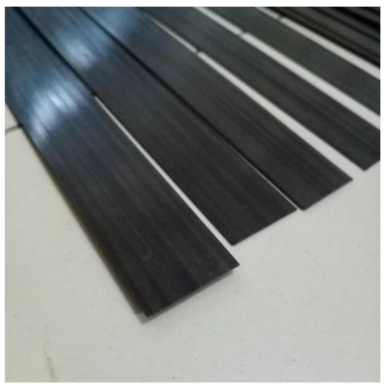
The other strengthening material used in this research is the carbon plates shown in Figure 2. The properties of the carbon plates are provided by the manufacturer Sika [33], a Swiss multinational specialty chemical company that supplies the building sector. They have a mean tensile strength of 3.1 GPa, a tensile modulus of elasticity of 165 GPa, a width of 50 mm, and a thickness of 2.5 mm. Table 2 summarizes the physical and mechanical properties of the utilized carbon plates. The strengthening carbon plates were fixed to the concrete surface using an adhesive epoxy. Table 3 demonstrates the properties of the epoxy used.

2.4. 3D-Printed Strips (CD)

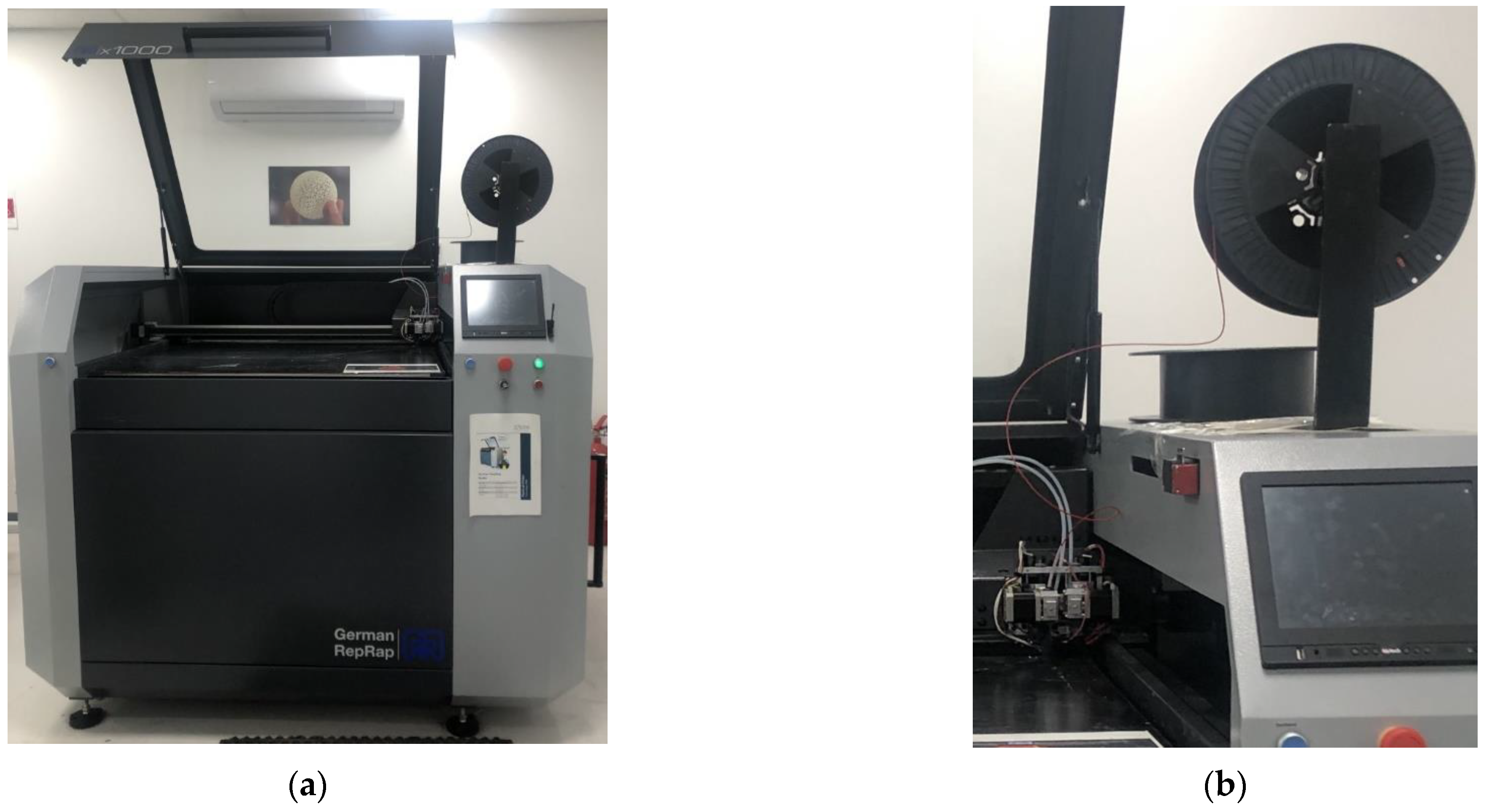
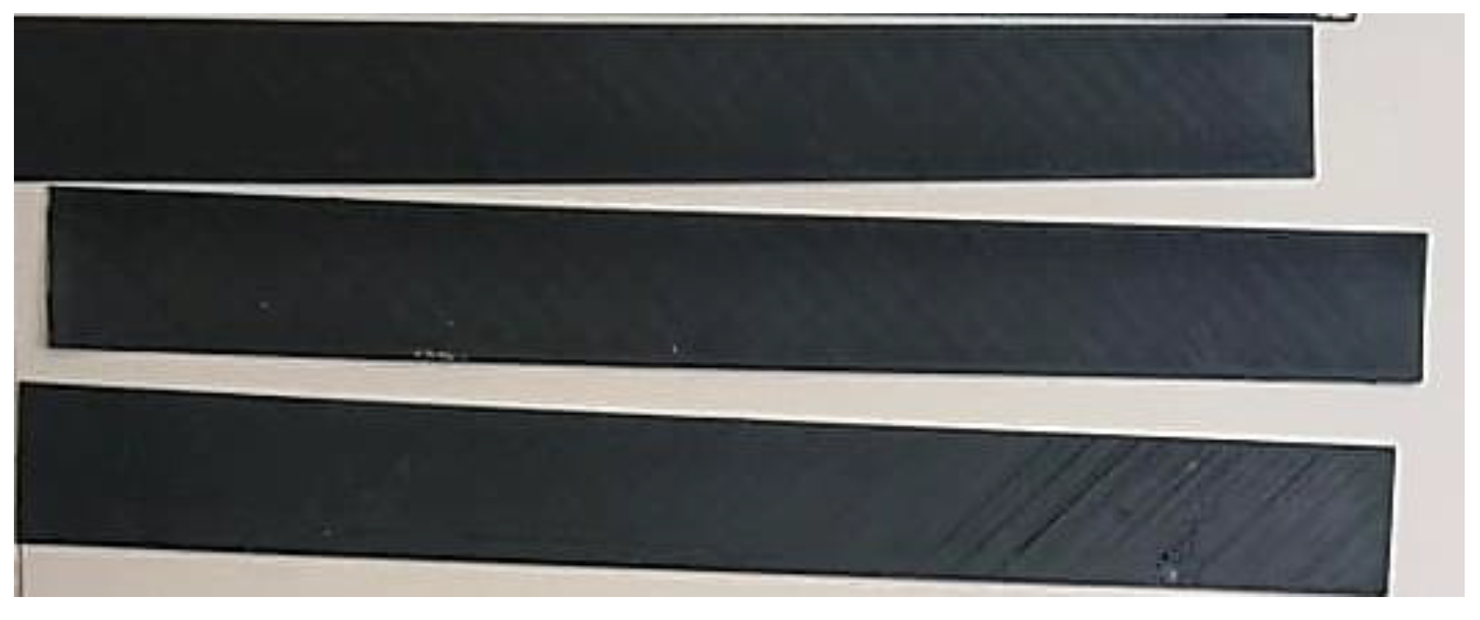
One beam was strengthened with novel 3D-printed strips. The German RepRap printer, shown in Figure 3, was used in this research to print the strips. The RepRap printer is based on the fused deposition modeling (FDM) technique called fused filament fabrication (FFF). FDM printers are the most popular types, and they work by extruding the filament through a heated nozzle. The FDM technique starts by melting the printing material and then applying it layer by layer to construct the 3D-printed strips, as shown in Figure 3b. Technical 3D-printing support was supplied by the Jordan Design and Development Bureau. The printed strips are shown in Figure 4, which consist of polylactic acid (PLA) and 20% ultra-light and relatively long stringer carbon fibers. The width and thickness of the printed strips were 50 mm and 1 mm, respectively. The average tensile strength, density, and elastic modulus of the 3D-printed strips were 52.5 MPa, 1290 kg/mm3, and 2.8 GPa, respectively, with a standard deviation of 1.22, 4.1, and 0.04, respectively. The strips were fixed to the concrete surface using an adhesive epoxy. The properties of the adhesive epoxy are shown in Table 3.

3. Experimental Program

3.1. Specimen Details

All test specimens were designed using ACI 318 [34] with shear deficiency to promote beam shear failure. The reinforcement details and the dimensions of the test specimens are presented in Figure 5. All beams have the same rectangular cross-section of 150 mm width and 250 mm depth. Furthermore, the total beam length is 1500 mm, including a simply supported span of 1400 mm and two overhangs of 50 mm each. The main longitudinal and shear beam reinforcements were the same for all test specimens. Two steel bars of Ø16 mm diameter were chosen as the longitudinal bottom reinforcement, while two steel bars of Ø10 mm were used as the top reinforcement, as illustrated in Figure 5. In addition, only two steel stirrups of Ø10 mm spaced at 1400 mm at the support were chosen as shear reinforcement and were only added to fix the longitudinal bars at their position. The spacing between stirrups is large in order to promote shear failure.
One specimen was designed as a control beam with no strengthening material for comparative purposes, as demonstrated in Figure 5. However, the other seven specimens were strengthened using different configurations, as shown in Figure 6, Figure 7, Figure 8, Figure 9 and Figure 10.
Two different parameters were used in the investigation of this experimental program. The first parameter was the type of the material, where three different types of materials were used: FRCM, CD, and CP. Specimens were strengthened from both sides. The second parameter was the configuration of the strengthening martial; four different orientations were used: (1) vertical strengthening configuration, (2) oblique strengthening configuration, (3) zigzag strengthening configuration, and (4) several-slanted configurations. The notation of the beams was described according to the strengthening configuration, “SV” indicates the vertical configuration, “SO” implies the oblique configuration, “SZ” stands for the zigzag configuration, and “SS” points to the several-slanted configurations.
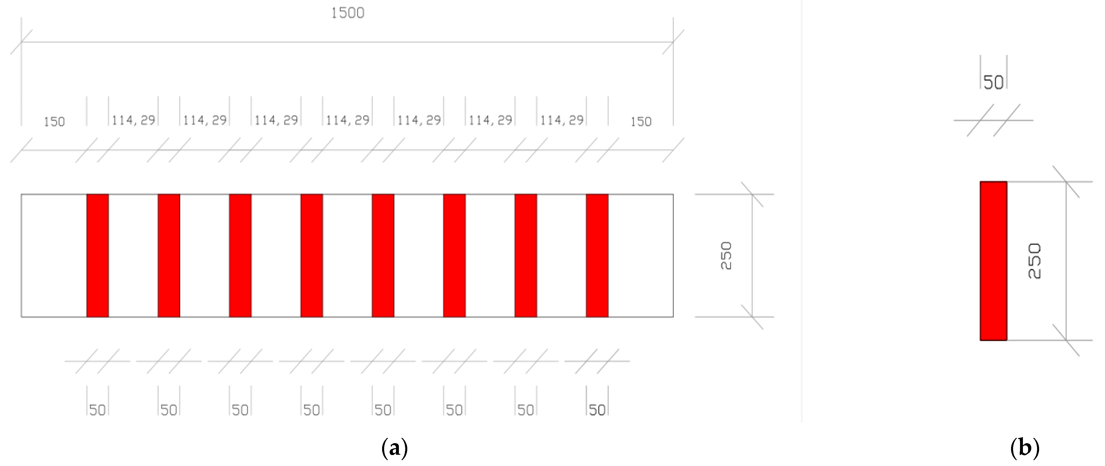
Three specimens were designed for the vertical configuration by applying three different types of materials. The details of the beam specimens, B2-SV-FRCM, B3-SV-CD, and B4-SV-CP, are shown in Figure 6. In addition, two specimens were designed using an oblique configuration, as illustrated in Figure 7 and Figure 8 for specimens B5-SO-CP and B6-SO-SV, respectively. One beam was prepared for each zigzag and several-slanted layout using FRCM strips, as demonstrated in Figure 9 and Figure 10 for B7-SZ-FR and B8-SS-FR, respectively.

3.2. Strengthening Configuration

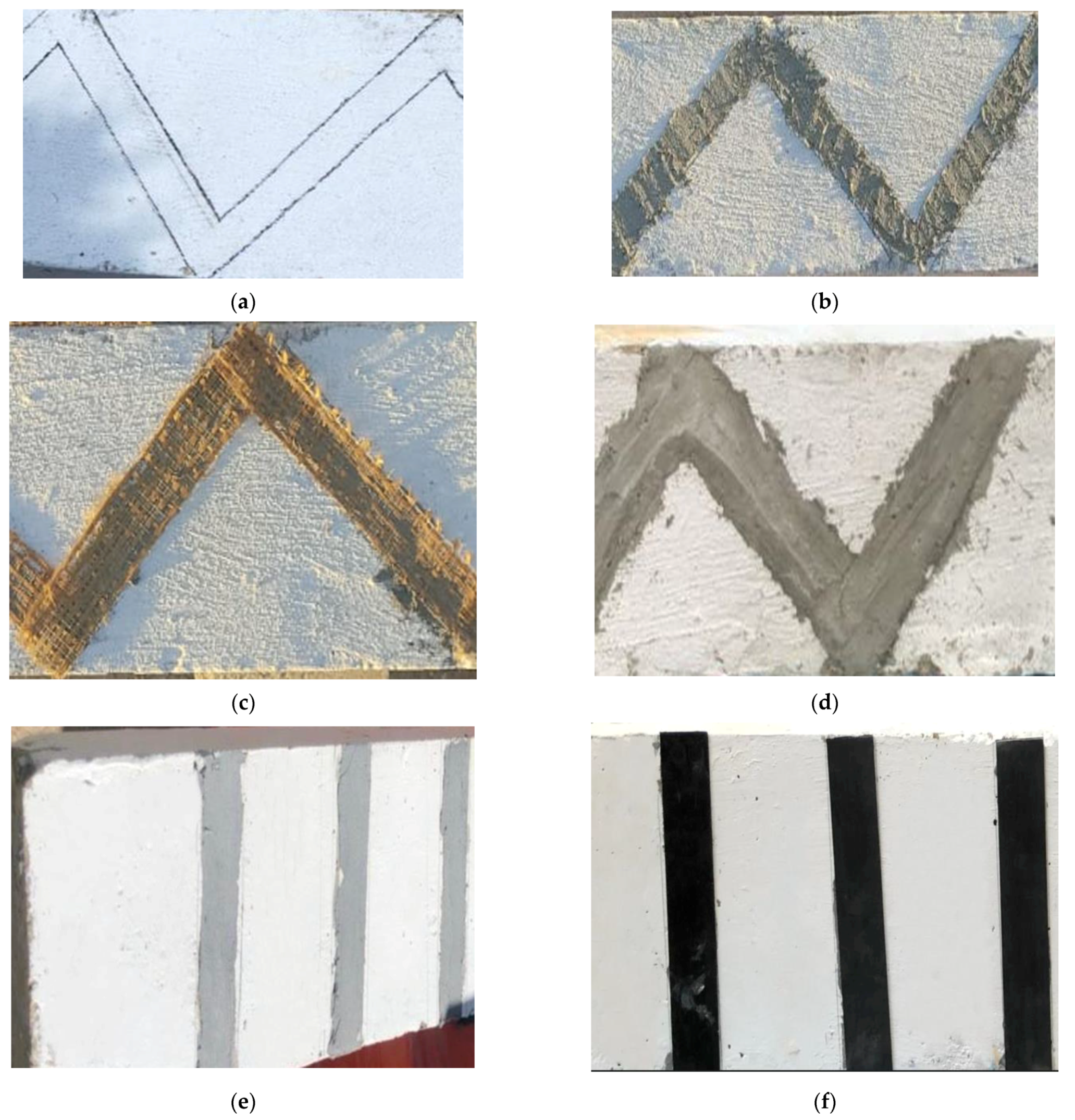
FRCM, CD, and CP materials were installed using the following procedure. First, all specimens were marked at the location of the strengthening material application, as shown in Figure 11a. This was followed by smoothing the surfaces with a smoothing grinder. Then, all materials were prepared and cut to the designed dimensions. For FRCM composites, the binding cementitious material was prepared by adding 25 kg of mortar to 7 L of water. The materials were then mixed for 5 min for a consistent homogeneous inorganic matrix, which has a thickness of 5 mm per layer and a compressive strength of 40 MPa, as provided by the manufacturer. The first layer of this binding material was initially applied, as shown in Figure 11b, followed by fixing of a layer of a bidirectional PBO-MESH, as shown in Figure 11c. A third layer of the stabilized inorganic matrix was then applied, as shown in Figure 11d.
The preparation of the CD and CP material was similar. Initially, an epoxy adhesive layer was first applied to bind CP and CD to the beam surface, as shown in Figure 11e. The CP and CD strips were then applied and fixed to the concrete surface to reduce air voids.

4. Test Setup

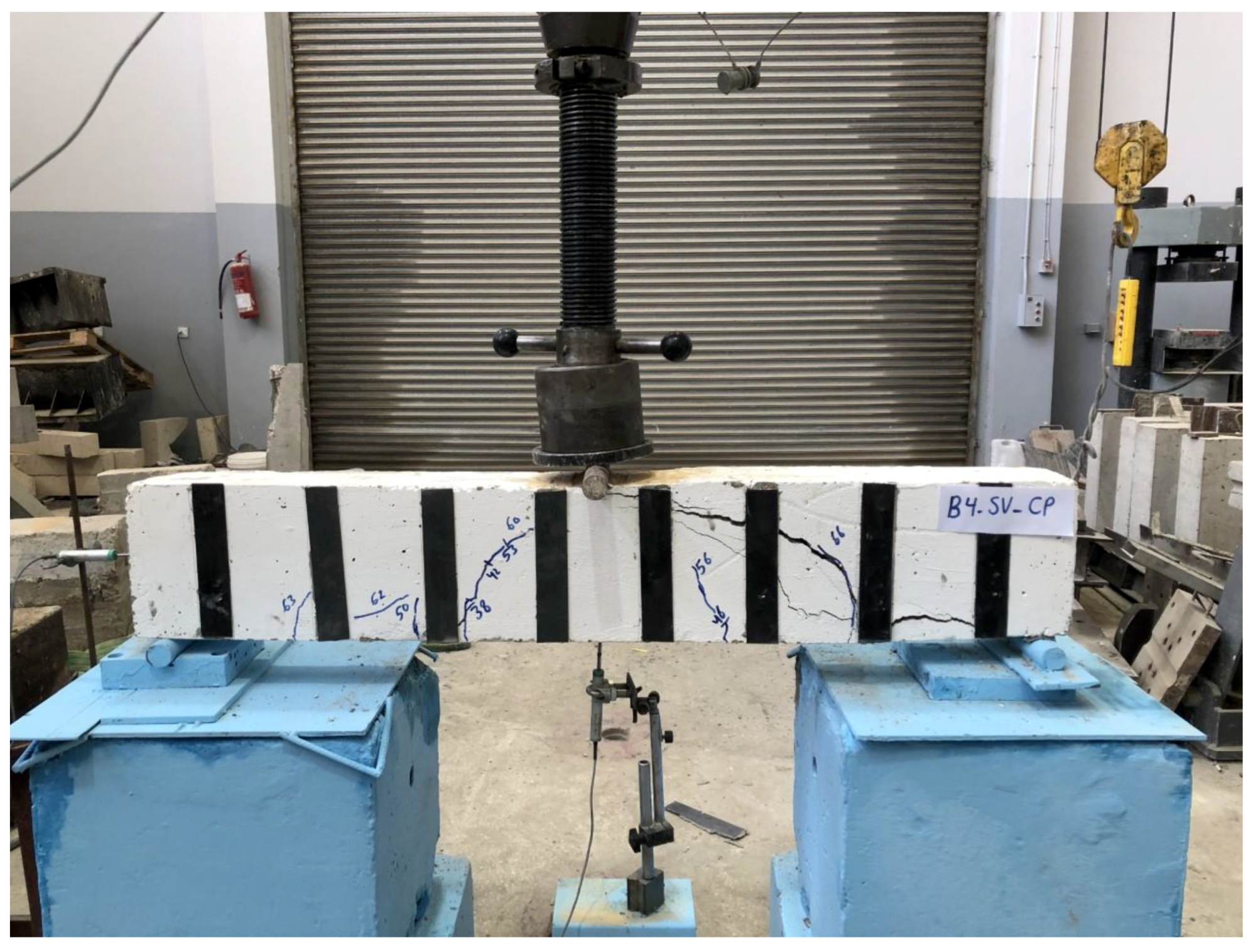
Figure 12 illustrates the test setup, where the beam specimens are simply supported. The beam specimens were tested under three-point bending, which was gradually applied through a hydraulic actuator that transferred the load to one rigid steel cylinder fixed at the loading point in the middle of the beam. The loads were applied vertically to the beam, and a load cell was fixed between the load collar and hydraulic actuator to track the load. The load application rate was 10 kN/min. The vertical mid-displacement was measured at each load increment using a Displacement transducer (LVDT) that was fixed at the beam mid-span, as shown in Figure 12.

5. Test Results and Discussion

Test results are presented in this section. An investigation was performed regarding the mode of failure, load capacity, load–displacement relationship, stiffness, and ductility. A comparison was made to investigate the influence of the strengthening material and the strengthening configuration on the shear behavior of RC beams.
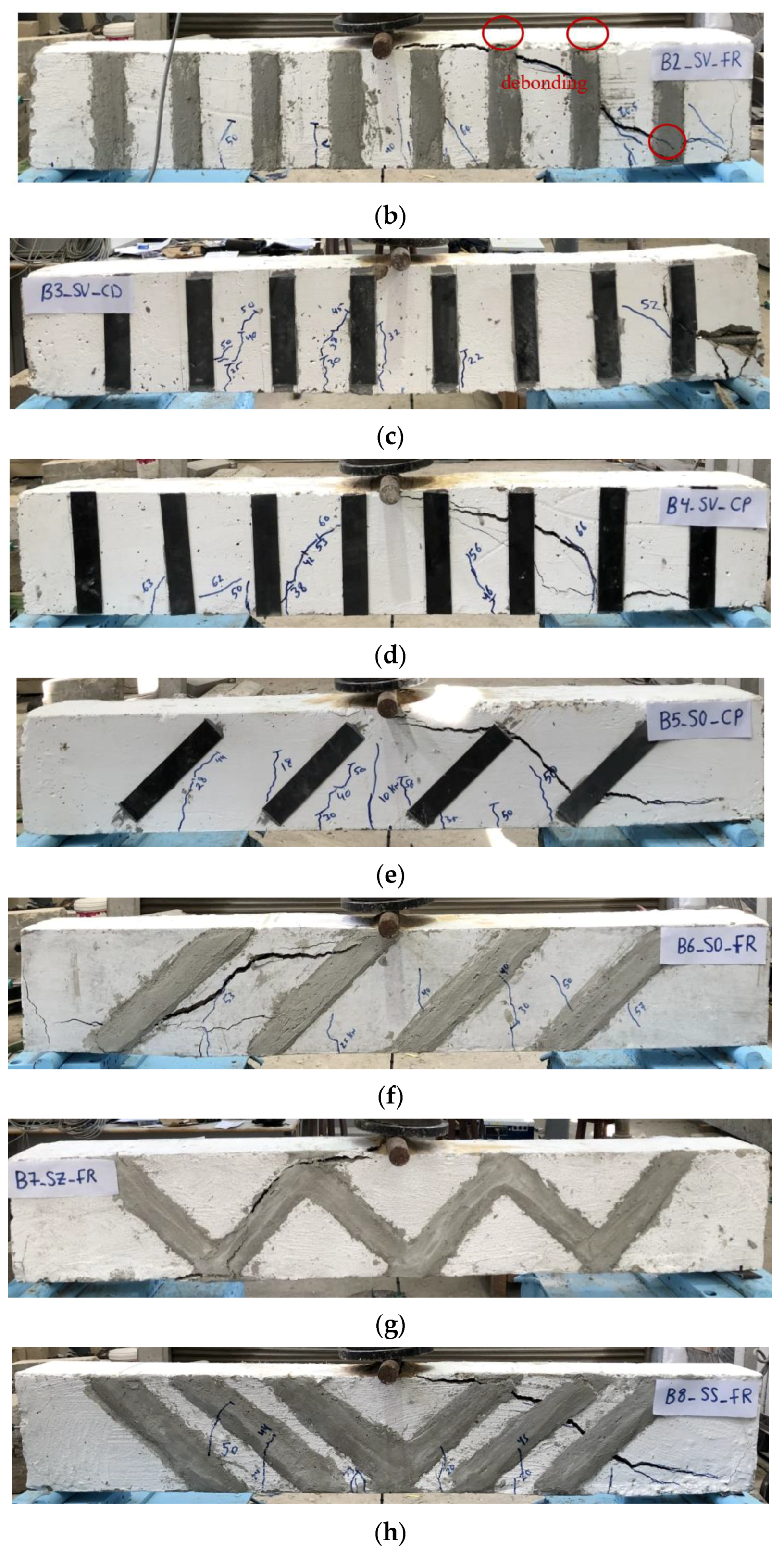
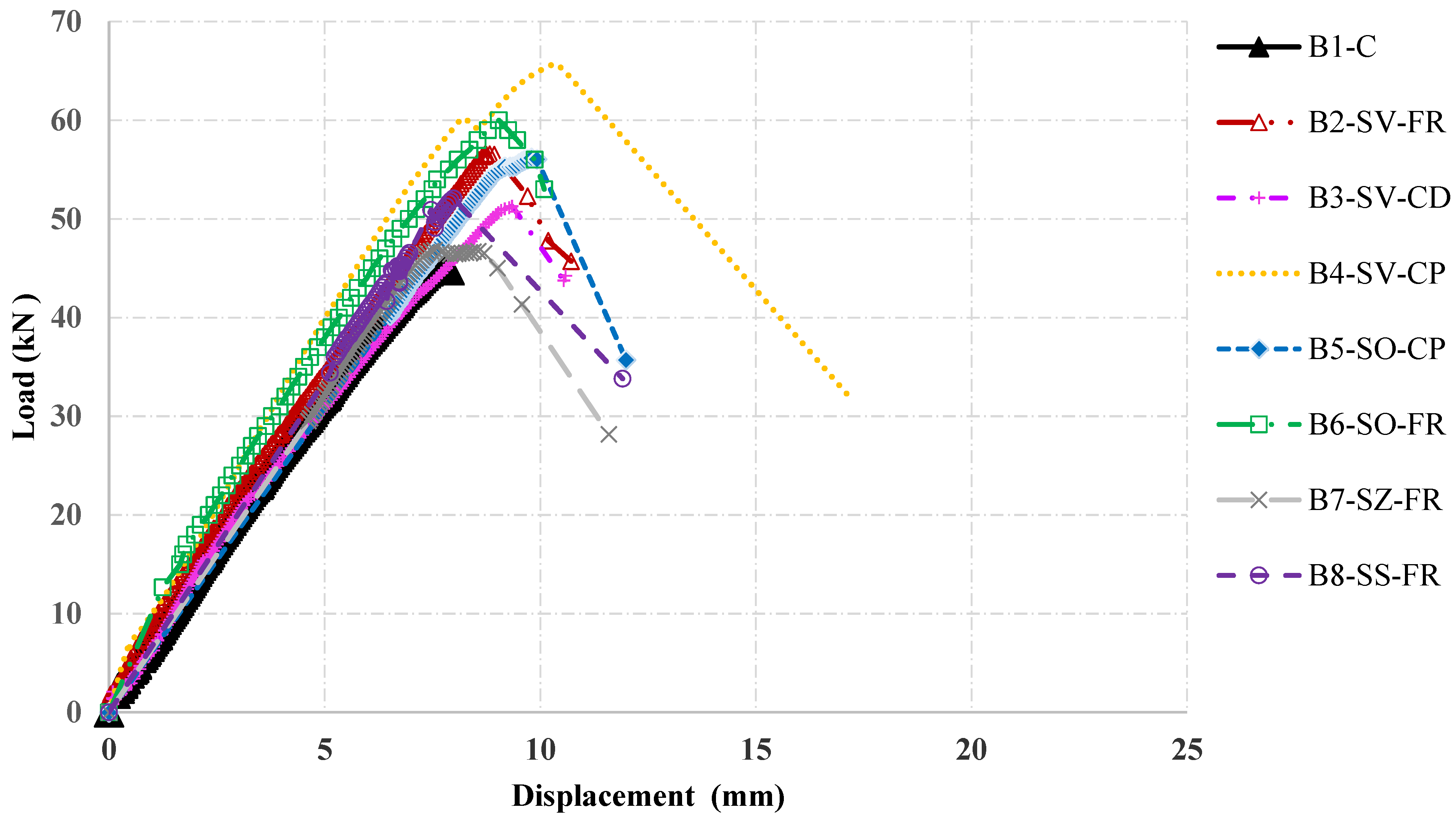
All test specimens were loaded until failure, as shown in Figure 13, and the load–deflection curves of the test specimens are presented in Figure 14. Table 4 demonstrates the test results in terms of the maximum load-carrying capacity, maximum deflection, mode of failure, ductility, and stiffness (yield load/deflection at yield load). The ductility index, µ u , was calculated using the model suggested by Park and Ang [35], as shown in Equation (1).
µ u = Δ m a x Δ y e i l d
where Δ m a x is the mid-span deflection at the maximum load and Δ y e i l d is the mid-span deflection at the hypothetical yield point of an equivalent elastic-plastic system whose equivalent elastic stiffness is the secant stiffness at 0.75 of the estimated peak load [36].

5.1. Control Specimen

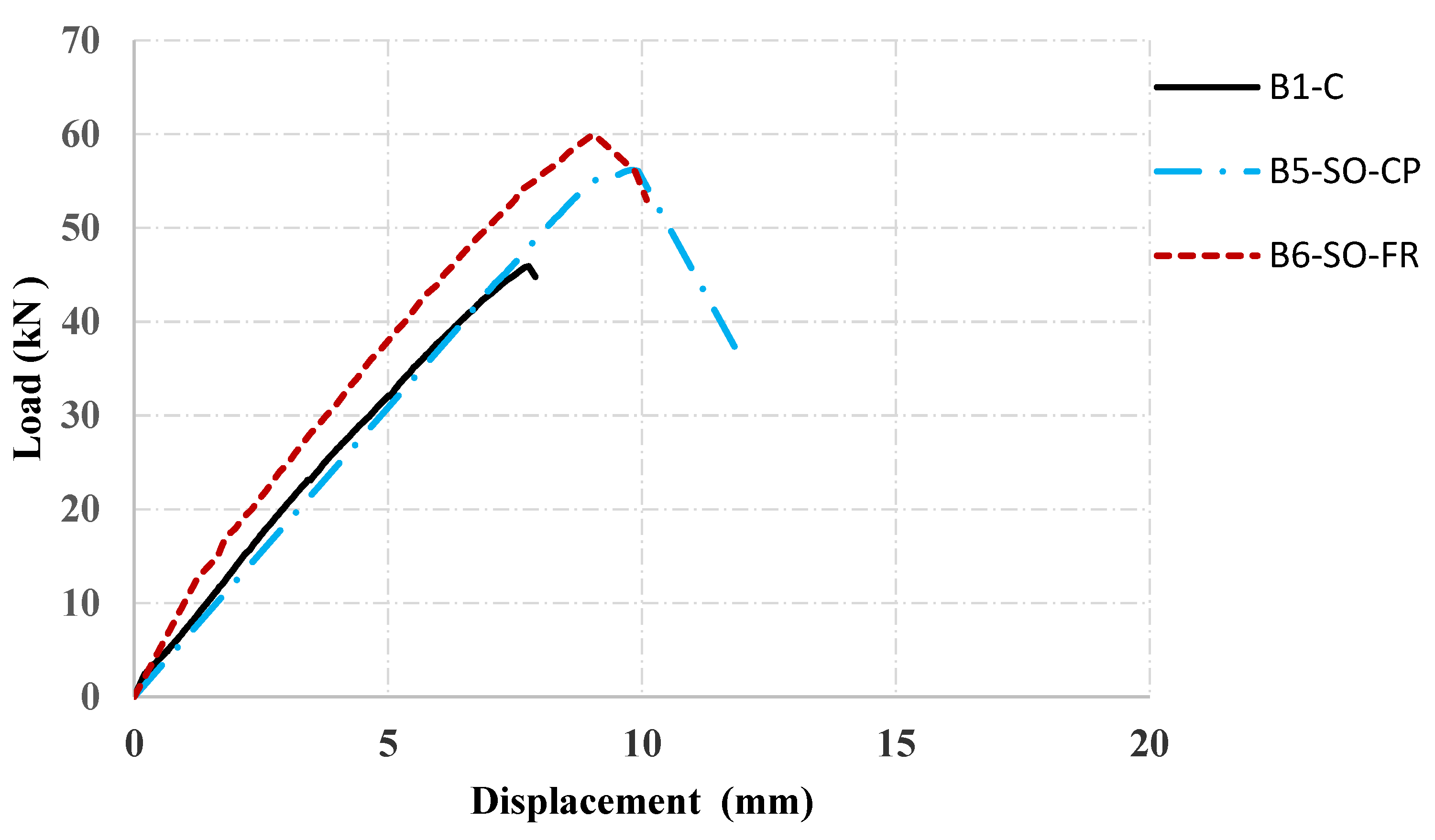
The mode of failure of the control beam, B1-C, is brittle shear, as shown in Figure 13a, where an inclined shear crack started from the support to the loading point, forming a major shear crack. The load–displacement curve of the control beam is shown in Figure 14. The beam exhibited an apparent reduction in initial stiffness after the first crack. There was a further reduction in the stiffness as the load increased until a sudden failure occurred by a dominant shear crack. The maximum load capacity and the maximum deflection of the control beam were 45.9 kN and 7.7 mm, respectively.

5.2. The Vertical Strengthening Configurations

The test specimens with vertical strengthening configurations, B2-SV-FR, B3-SV-CD, and B4-SV-CP, were strengthened using vertical FRCM, CD, and CP materials, as shown in Figure 6. The mode of failure of the tested beams B2-SV-FR, B3-SV-CD, and B4-SV-CP is shear, as shown in Figure 13a–c, respectively. Figure 15 demonstrates the load–deflection relationship for test specimens strengthened with vertical strips. The utilization of the CP as a shear-strengthening material improved the load-carrying capacity of all test specimens compared with the control beam. The load capacity enhancements for B2-SV-FR, B3-SV-CD, and B4-SV-CP were 23%, 12% and 43%, respectively. Although the tensile strength of the FRCM material was higher than that of the CP strips, the total load capacity of B2-SV-FR was lower than that of B4-SV-CP. This is due to the debonding of FRCM strips at failure in the vertical configuration, as shown in Figure 7b, preventing the material from reaching its maximum strength capacity. In addition, the thickness of the CP plates (2.5 mm) was higher than that found in the FRCM strips (0.0455 mm), increasing the load-carrying capacity of the beam strengthened with the CP strips. Beam B3-SV-CD, which was strengthened using CD strips, achieved the lowest load-carrying capacity enhancement compared with the control beam because it had the lowest tensile strength compared with the other materials.
Moreover, at the same loading value (taken at the control specimen’s peak load), the deflection of B2-SV-FR and B4-SV-CP was lower than the control beam due to the enhancement of the initial stiffness of the strengthened beams compared with the control beam, as listed in Table 4. The enhancements of the initial stiffnesses of B2-SV-FR and B4-SV-CP were 8.4% and 7%, respectively. However, the stiffness of B3-SV-CD was similar to that measured in the control beam because the tensile strength of CD was lower than that found in the other strengthening materials.
The mode of failure of the beam specimens strengthened with vertical strips was brittle shear failure, similar to that depicted in the control beam. However, debonding of the FRCM strips was observed in beam B2-SV-FR. Debonding occurred in the beam strengthened with FRCM composites, while the beam strengthened with CP did not experience any debonding because the tensile strength of the epoxy binding material of CP (18 MPa) is 4.5 times that found in the cementitious binding material with FRCM (4 MPa).
The ductility indices of the test specimens were found using Equation (1) and are presented in Table 4. The improvements in the ductility indices for B2-SV-FR, B3-SV-CD, and B4-SV-CP over the control beam were 3.7%, 0.4%, and 22.8%, respectively. The increments in the ductility indices of the beams B2-SV-FR and B4-SV-CP is due to the high tensile modulus of elasticity for FRCM (270 GPa) and CP (165 GPa) compared with the control beam. However, the debonding of FRCM limited beam B2-SV-FR from reaching its maximum ductility. Furthermore, the ductility index of beam B3-SV-CD was lower than that measured in the other strengthened beams because it had the lowest modulus of elasticity (2.7 GPa).
The previously discussed results indicate the efficiency of using FRCM and CP materials for shear strengthening in terms of load-carrying capacity, initial stiffness, and ductility. However, using CD shows a limited effect on enhancing the performance of the shear-strengthened beams.

5.3. The Oblique Strengthening Configurations

Beams B5-SO-FR and B6-SO-CP were strengthened using an oblique configuration, as shown in Figure 7. The load–displacement relationship for the oblique strengthening configuration is shown in Figure 16. Both strengthening materials, CP and FRCM, improved the load-carrying capacity of the beams. The load enhancements in beams B5-SO-CP and B6-SO-FR were 22.4% and 30.7%, respectively. This is due to the high tensile strength of FRCM (5800 MPa) and CP (3100 MPa), which enhanced the load-carrying capacity of the beams. Figure 13e,f show the mode of failures of the tested beams, respectively, where a brittle shear failure occurred in both specimens, similar to the control beam. Furthermore, using FRCM in the oblique configuration for beam B6-SO-FR efficiently enhanced the stiffness, where the enhancement percentage in the initial stiffness for beam B6-SO-FR was 23.7% compared with the control beam, as listed in Table 4. However, the strengthening material CP in beam B5-SO-CP has a limited effect on the stiffness of the beam because the tensile strength of FRCM is almost 1.9 that of the CP material. Additionally, the application of CP in the oblique configuration was not extended to the full beam height, unlike FRCM, which reduced the efficiency of the plates (less effective depth).
The improvements in the ductility indices for beams B5-SO-FR and B6-SO-CP over the control beam were 7.4% and 10.7%, respectively. This is attributed to the high value of the modulus of elasticity of the strengthening materials FRCM (270 GPa) and CP (165 GPa).

5.4. FRCM Strengthening Configurations

Four beams were strengthened using FRCM, employing four strengthening configurations to find the best layout for shear enhancement. Figure 5b,f–h present the mode of failure for the test specimens. All test specimens experienced a similar brittle shear failure, whereas beam B2-SV-FR was the only specimen that exhibited debonding of FRCM strips combined with brittle shear failure.
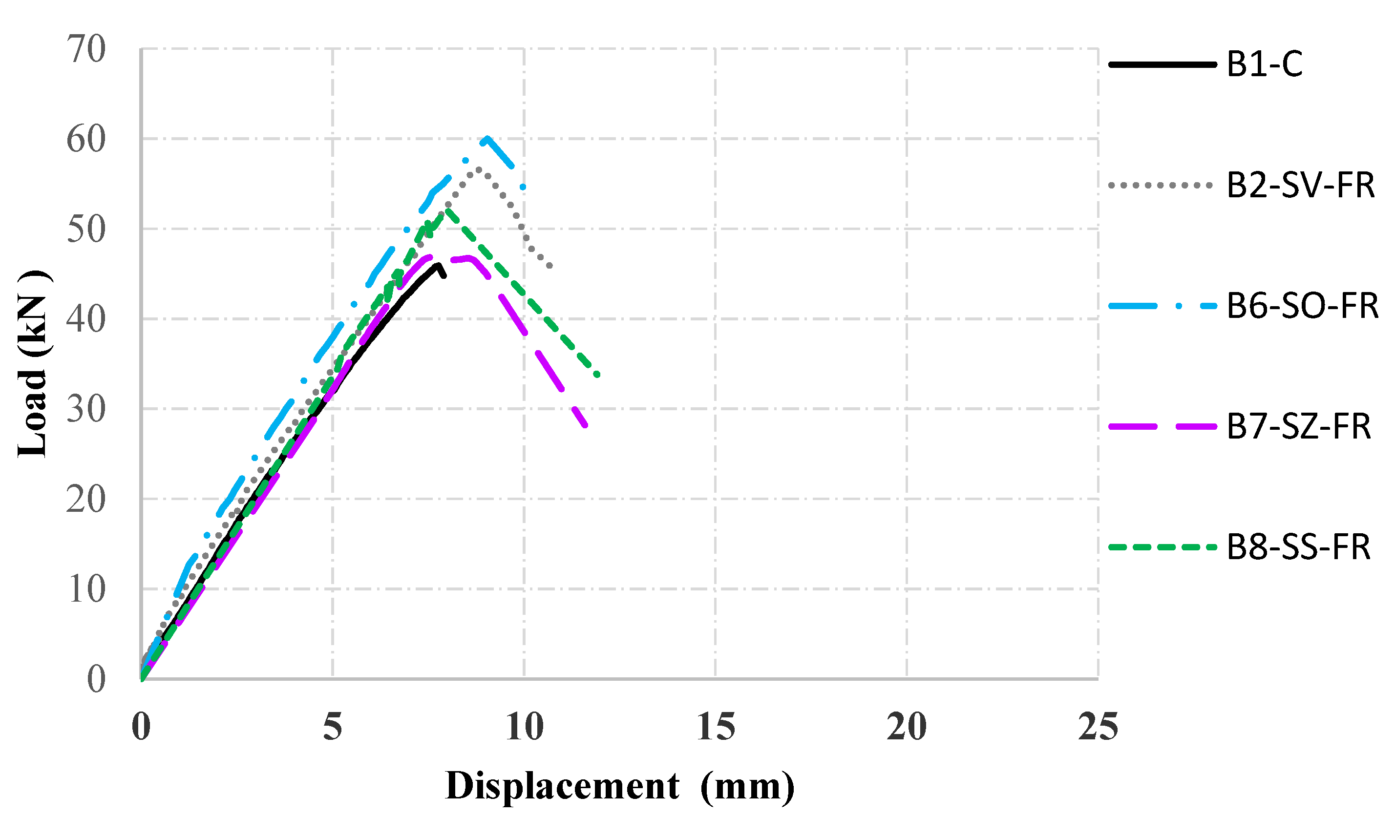
Figure 17 shows the load–deflection curves for the beams strengthened with FRCM, B2-SV-FR, B6-SO-FR, B7-SZ-FR, and B8-SS-FR. The oblique and vertical configurations were the most effective arrangements for enhancing the load-carrying capacity of the beams. The improvement percentages in the load-carrying capacity for beams B6-SO-FR and B2-SV-FR were 25% and 23%, respectively, compared with the control beam, while they were 2% and 13% for beams B7-SZ-FR, and B8-SS-FR, respectively. This is attributed to the fact that the application of FRCM in the oblique configuration limited the propagation of the shear cracks because they were virtually developed in the opposite direction. Furthermore, the debonding of FRCM composites in the vertical configuration prevented them from reaching their maximum strength capacity. However, the vertical configuration is more efficient than the zigzag or several-slanted layouts because the spacing between FRCM strips in the vertical configuration (114.29 cm) was lower than that adopted in the zigzag (366.67 cm) and several-slanted layouts (125 cm), increasing the number of FRCM strips. One last reason is the fact that strips parallel to the shear cracks will make a minimal contribution.
The deflection of the tested beams at the same loading values was lower than that depicted in the control beam due to the improvement in stiffness in the strengthened specimens, as demonstrated in Figure 17. The initial stiffness values of beams B2-SV-FR, B6-SO-FR, B7-SZ-FR, and B8-SS-FR were higher than that measured in the control specimen by 5.7%, 16.8%, 2.3%, and 8%, respectively, as listed in Table 4. Similarly, the ductility indices of the test specimens B2-SV-FR, B6-SO-FR, B7-SZ-FR, and B8-SS-FR were greater than that calculated in the control beam by 3.7%, 10.7%, 3.6%, and 4.1% respectively. Test results showed that the direction and spacing of the strengthening material are predominant factors in enhancing the shear behavior of RC beams.

5.5. Carbon Plates Strengthening Configurations

The CP material was used to strengthen two beam specimens employing oblique and vertical configurations. The modes of failure for beams B4-SV-CP and B5-SO-CP are shown in Figure 18d,e, respectively. Both beams experienced the same mode of failure of brittle shear, similar to that depicted in the control beam.
The load–deflection curves of the tested beams are demonstrated in Figure 6. The vertical strengthening configuration was more efficient than the oblique configuration for the CP material in terms of load-carrying capacity, deflection, stiffness, and ductility. This is attributed to the fact that the oblique configuration with CP material was not extended to the top and bottom ends of the beam, whereas the vertical layout was extended to both ends. The improvements in the load-carrying capacity, initial stiffness, and ductility index with the vertical strengthening configuration were 43.1%, 23.2%, and 22.8%, respectively.
In addition, the spacing between the vertical strips (114.29 mm) was less than that adopted in the oblique configuration (250 mm), increasing the total number of strips and hence limiting the propagation of the diagonal shear cracks. To summarize the improvements in shear capacity regarding the un-strengthened specimen, Figure 19 shows the percentage increase in the shear capacity for each type and configuration of strengthening.

6. Prediction of the Shear Strength Using ACI 440.2R-17

It is well recognized that wrapping, or partially wrapping, RC members with FRP systems increases the shear capacity when they are placed perpendicular to the member’s axis or the potential shear crack. The ACI 440.2R-17 [29] presents guidance for calculating the added shear strength of FRP-strengthened members. The nominal shear strength of FRP-strengthened members can be determined by adding the additional shear capacity provided by the FRP (Vf) to the shear contribution of concrete (Vc) and steel (Vs), as shown in Equation (2), where Vc and vs. can be calculated according to ACI 318-19 [34] and Ψf is a bond-dependent reduction factor equal to 0.85 for two- and three-side wrapping.
Vn = Vc + Vs + Ψf Vf
The added shear contribution can be determined by calculating the force carried by the FRP across the assumed crack, as shown in Equation (3), where Afv, ffe, α, dfv, and Sf are the area of the FRP laminate, effective tensile stress in the FRP at a nominal strength, angle of the FRP laminates, effective depth of the FRP laminates, and spacing of the FRP laminates, respectively. The Afv of a rectangular FRP laminate is calculated according to Equation (4), where n is the number of FRP plies. All dimensions are illustrated in Figure 20. It should be noted that the effective tensile stress in FRP laminates is obtained using Equation (5), where the effective strain (εfe) is determined based on ACI 440.2R-17.
V f = A f v   f f e ( s i n + c o s ) d f v S f
A f v = 2   n   t f   w f
f f e = E f   ε f e
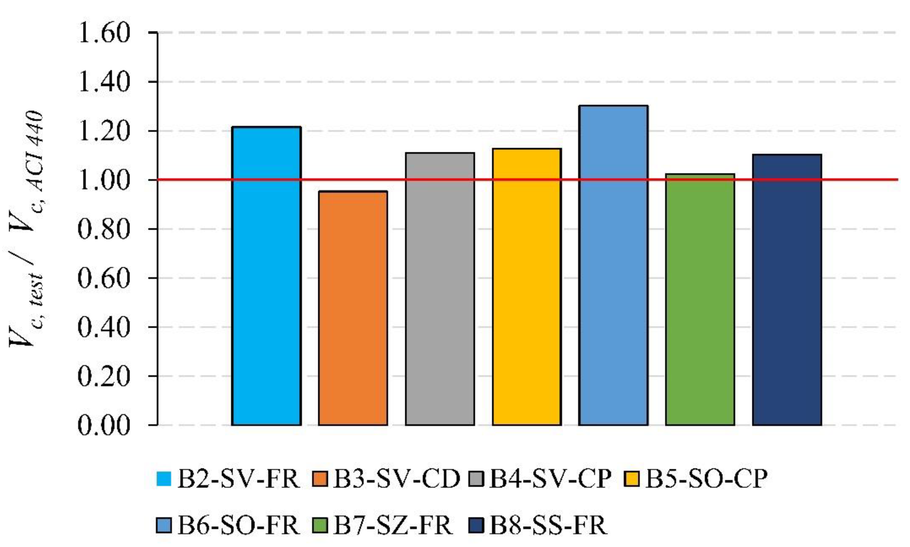
Following the ACI 440.2R-17 procedure for determining the shear strength of FRP-strengthened members, Figure 21 presents the tested-to-predicted shear strength ratio for each specimen. It can be noted that the ACI 440.2R-17 model yielded accurate predictions with an average (Vc, test/Vc, ACI 440) of 1.11. Specimen B3-SV-CD is the only specimen with (Vc, test/Vc, ACI 440) lower than 1; this can be attributed to the low strength of the 3D-printed material.

7. Conclusions

An experimental program was conducted to investigate the shear behavior of RC beams strengthened with various types of strengthening materials and configurations. Eight simply supported beams were prepared to find the most efficient shear-strengthening configuration and material for RC beams. One specimen was designed as a control beam without any strengthening material, while the other beams were strengthened using various configurations; vertical, oblique, zigzag, and several-slanted layouts. Three types of strengthening materials were used: FRCM, CD, and CP. The following conclusions were drawn based on the results achieved:
  • FRCM and CP are both efficient for shear strengthening in terms of maximum load capacity, initial stiffness, and ductility. However, CD showed a limited effect on enhancing the performance of shear-strengthened beams due to its lower tensile strength.
  • The best shear enhancement was found in the beam strengthened with vertical CP, with improvements in load-carrying capacity, stiffness, and ductility of 43%, 23%, and 23%, respectively.
  • The direction, spacing, thickness, and tensile strength of the strengthening material are key factors that play the primary role in enhancing the shear behavior of the RC beams.
  • Vertical and oblique strengthening configurations were more efficient than zigzag and several-slanted layouts for RC beams strengthened with FRCM strips. The enhancements in load-carrying capacity for the oblique and vertical layouts were 23% and 25%, respectively, compared with 2% and 13% for the zigzag and several-slanted configurations.
  • The ACI 440.2R-17 model yielded accurate predictions for the shear capacity of the strengthened specimens with an average (Vc, test/Vc, ACI 440) of 1.11.

Author Contributions

Methodology, Y.Z.M.; Validation, Y.Z.M.; Formal analysis, A.T.; Investigation, Y.Z.M., H.A.-M. and A.T.; Resources, Y.Z.M.; Writing—original draft, Y.Z.M. and H.A.-M.; Writing—review & editing, Y.Z.M. and A.T.; Supervision, Y.Z.M.; Project administration, A.J.A., A.A., R.A.H. and R.S.; Funding acquisition, R.A.H. and R.S. All authors have read and agreed to the published version of the manuscript.

Funding

This research was funded by The University of Jordan grant number [1]. And The APC was funded by The University of Jordan.

Institutional Review Board Statement

Not applicable.

Informed Consent Statement

Not applicable.

Data Availability Statement

Data is contained within the article.

Acknowledgments

The financial support of the deanship of academic research at the University of Jordan and the technical 3D printing support of the Jordan Design and Development Bureau are highly appreciated.

Conflicts of Interest

The authors declare no conflict of interest.

References

  1. Yu, X.; Xing, G.; Chang, Z. Flexural Behavior of Reinforced Concrete Beams Strengthened with Near-Surface Mounted 7075 Aluminum Alloy Bars. J. Build. Eng. 2020, 31, 101393. [Google Scholar] [CrossRef]
  2. Yang, J.; Wang, L. Experimental Research on Flexural Behaviors of Damaged PRC Beams Strengthened with NSM CFRP Strips. Constr. Build. Mater. 2018, 190, 265–275. [Google Scholar] [CrossRef]
  3. Hosen, M.A.; Jumaat, M.Z.; Alengaram, U.J.; Islam, A.B.M.S.; Hashim, H. bin Near Surface Mounted Composites for Flexural Strengthening of Reinforced Concrete Beams. Polymers 2016, 8, 67. [Google Scholar] [CrossRef] [Green Version]
  4. Murad, Y.Z.; Aljaafreh, A.J.; Almashaqbeh, A.; Alfaouri, Q.T. Cyclic Behaviour of Heat-Damaged Beam–Column Joints Modified with Nano-Silica, Nano-Titanium, and Nano-Alumina. Sustainability 2022, 14, 10916. [Google Scholar] [CrossRef]
  5. Golias, E.; Zapris, A.G.; Kytinou, V.K.; Osman, M.; Koumtzis, M.; Siapera, D.; Chalioris, C.E.; Karayannis, C.G. Application of X-Shaped CFRP Ropes for Structural Upgrading of Reinforced Concrete Beam–Column Joints under Cyclic Loading–Experimental Study. Fibers 2021, 9, 42. [Google Scholar] [CrossRef]
  6. Wakjira, T.G.; Ebead, U. Hybrid NSE/EB Technique for Shear Strengthening of Reinforced Concrete Beams Using FRCM: Experimental Study. Constr. Build. Mater. 2018, 164, 164–177. [Google Scholar] [CrossRef]
  7. Younis, A.; Ebead, U.; Shrestha, K.C. Different FRCM Systems for Shear-Strengthening of Reinforced Concrete Beams. Constr. Build. Mater. 2017, 153, 514–526. [Google Scholar] [CrossRef]
  8. Marcinczak, D.; Trapko, T.; Musiał, M. Shear Strengthening of Reinforced Concrete Beams with PBO-FRCM Composites with Anchorage. Compos. Part B Eng. 2019, 158, 149–161. [Google Scholar] [CrossRef]
  9. Yang, X.; Gao, W.Y.; Dai, J.G.; Lu, Z.D. Shear Strengthening of RC Beams with FRP Grid-Reinforced ECC Matrix. Compos. Struct. 2020, 241, 112120. [Google Scholar] [CrossRef]
  10. Murad, Y.Z. Retrofitting Heat-Damaged Non-Ductile RC Beam-to-Column Joints Subjected to Cyclic and Axial Loading with FRCM Composites. J. Build. Eng. 2022, 48, 103952. [Google Scholar] [CrossRef]
  11. Haddad, R.H.; Almasaeid, H.H. Recovering Shear Capacity of Heat-Damaged Beams Using NSM-CFRP Strips. Constr. Build. Mater. 2016, 105, 448–458. [Google Scholar] [CrossRef]
  12. Mhanna, H.H.; Hawileh, R.A.; Abdalla, J.A. Shear Behavior of RC T-Beams Externally Strengthened with Anchored High Modulus Carbon Fiber-Reinforced Polymer (CFRP) Laminates. Compos. Struct. 2021, 272, 114198. [Google Scholar] [CrossRef]
  13. Shomali, A.; Mostofinejad, D.; Esfahani, M.R. Experimental and Numerical Investigation of Shear Performance of RC Beams Strengthened with FRP Using Grooving Method. J. Build. Eng. 2020, 31, 101409. [Google Scholar] [CrossRef]
  14. Kotynia, R.; Oller, E.; Marí, A.; Kaszubska, M. Efficiency of Shear Strengthening of RC Beams with Externally Bonded FRP Materials—State-of-the-Art in the Experimental Tests. Compos. Struct. 2021, 267, 113891. [Google Scholar] [CrossRef]
  15. Al-Shamayleh, R.; Al-Saoud, H.; Abdel-Jaber, M.; Alqam, M. Shear and Flexural Strengthening of Reinforced Concrete Beams with Variable Compressive Strength Values Using Externally Bonded Carbon Fiber Plates. Results Eng. 2022, 14, 100427. [Google Scholar] [CrossRef]
  16. Mohamed, K.; Abdalla, J.A.; Hawileh, R.A. Experimental and Analytical Investigations of the Use of Groove-Epoxy Anchorage System for Shear Strengthening of RC Beams Using CFRP Laminates. Materials 2020, 13, 4350. [Google Scholar] [CrossRef]
  17. Askar, M.K.; Hassan, A.F.; Al-Kamaki, Y.S.S. Flexural and Shear Strengthening of Reinforced Concrete Beams Using FRP Composites: A State of the Art. Case Stud. Constr. Mater. 2022, 17, e01189. [Google Scholar] [CrossRef]
  18. Godat, A.; Hammad, F.; Chaallal, O. State-of-the-Art Review of Anchored FRP Shear-Strengthened RC Beams: A Study of Influencing Factors. Compos. Struct. 2020, 254, 112767. [Google Scholar] [CrossRef]
  19. Al-Rousan, R.Z. Shear Behavior of RC Beams Externally Strengthened and Anchored with CFRP Composites. Struct. Eng. Mech. 2017, 63, 456. [Google Scholar] [CrossRef]
  20. Mukhtar, F.; Deifalla, A. Shear Strength of FRP Reinforced Deep Concrete Beams without Stirrups: Test Database and a Critical Shear Crack-Based Model. Compos. Struct. 2023, 307, 116636. [Google Scholar] [CrossRef]
  21. Karayannis, C.G.; Kosmidou, P.-M.K.; Chalioris, C.E. Reinforced Concrete Beams with Carbon-Fiber-Reinforced Polymer Bars—Experimental Study. Fibers 2018, 6, 99. [Google Scholar] [CrossRef] [Green Version]
  22. Chalioris, C.E.; Zapris, A.G.; Karayannis, C.G. U-Jacketing Applications of Fiber-Reinforced Polymers in Reinforced Concrete T-Beams against Shear—Tests and Design. Fibers 2020, 8, 13. [Google Scholar] [CrossRef] [Green Version]
  23. Saadah, M.; Ashteyat, A.; Murad, Y. Shear Strengthening of RC Beams Using Side near Surface Mounted CFRP Ropes and Strips. Structures 2021, 32, 380–390. [Google Scholar] [CrossRef]
  24. Murad, Y.; Abu-AlHaj, T. Novel 3D Printed Bars for Retrofitting Heat Damaged RC Beams. Structures 2021, 34, 3427–3435. [Google Scholar] [CrossRef]
  25. Murad, Y.; Alseid, B. Poly-Lactic Acid and Carbon Fibers 3D Printed Bars for Seismic Retrofitting RC Beam-to-Column Joints Subjected to Elevated Temperature. Structures 2022, 43, 1530–1547. [Google Scholar] [CrossRef]
  26. Aksoylu, C.; Özkılıç, Y.O.; Hadzima-Nyarko, M.; Işık, E.; Arslan, M.H. Investigation on Improvement in Shear Performance of Reinforced-Concrete Beams Produced with Recycled Steel Wires from Waste Tires. Sustainability 2022, 14, 13360. [Google Scholar] [CrossRef]
  27. Abdulhameed, A.A.; Hanoon, A.N.; Abdulhameed, H.A.; Banyhussan, Q.S.; Mansi, A.S. Push-out Test of Steel–Concrete–Steel Composite Sections with Various Core Materials: Behavioural Study. Arch. Civ. Mech. Eng. 2021, 21, 1–21. [Google Scholar] [CrossRef]
  28. Abdulhameed, H.; Abdulhameed, A.; Mansi, A.; Hanoon, A.; Mohammed, A. Study the Use of Nano-Limestone and Egg-Shell Ash in Eco-Friendly SCC: An Experimental and Statistical Evaluation Based on Computer Programming. In Proceedings of the 14th International Conference on Developments in eSystems Engineering, DeSE, Sharjah, United Arab Emirates, 7–10 December 2021; Institute of Electrical and Electronics Engineers Inc.: Piscataway, NJ, USA, 2021; Volume 2021, pp. 509–514. [Google Scholar]
  29. ACI Committee 440. Guide for the Design and Construction of Externally Bonded FRP Systems for Strengthening Concrete Structures; ACI Committee: Farmington Hills, MI, USA, 2017. [Google Scholar]
  30. ASTM C39/C39M-20; Standard Test Method for Compressive Strength of Cylindrical Concrete Specimens; ASTM: West Conshohocken, PA, USA, 2020.
  31. ASTM A370-20; Standard Test Methods and Definitions for Mechanical Testing of Steel Products; ASTM: West Conshohocken, PA, USA, 2020.
  32. Ruregold Ruregold. Available online: https://ruregold.com/company/ (accessed on 2 February 2023).
  33. Sika. Available online: https://www.sika.com/ (accessed on 2 February 2023).
  34. ACI 318-19; Building Code Requirements for Structural Concrete (ACI 318-19) and Commentary; ACI: Farmington Hills, MI, USA, 2019.
  35. Park, Y.; Ang, A.H.-S. Mechanistic Seismic Damage Model for Reinforced Concrete. J. Struct. Eng. 1985, 111, 722–739. [Google Scholar] [CrossRef]
  36. Kwan, A.K.H.; Ho, J.C.M.; Pam, H.J. Flexural Strength and Ductility of Reinforced Concrete Beams. ICE Proc. Struct. Build. 2002, 152, 361–369. [Google Scholar] [CrossRef]
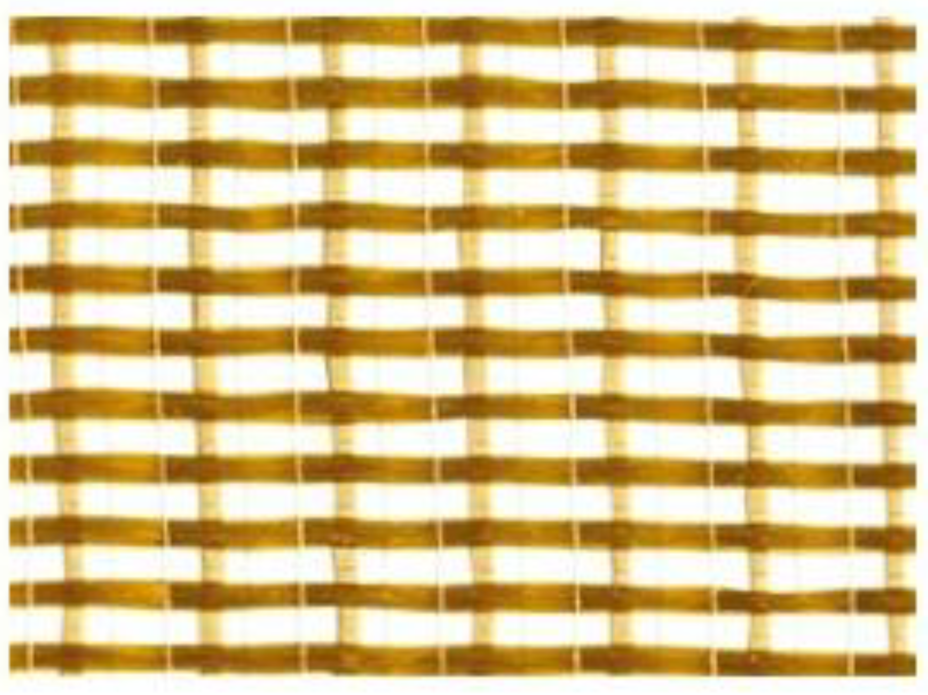
Figure 1. The bidirectional PBO-MESH.
Sustainability 15 04293 g001
Figure 2. Carbon plates.
Sustainability 15 04293 g002
Figure 3. (a) The German RepRap printer, (b) The FDM printer nozzle and printing material.
Sustainability 15 04293 g003
Figure 4. Sample of the 3D-Printed Strips.
Sustainability 15 04293 g004
Figure 5. Reinforcement details of the tested beams (dimensions in mm). (a) Longitudinal section. (b) Cross-section.
Sustainability 15 04293 g005
Figure 6. Details of the vertical configuration for beams (B2-SV-FRCM, B3-SV-CD and B4-SV-CP). (a) Longitudinal section (mm). (b) Material details.
Sustainability 15 04293 g006
Figure 7. Details of the oblique configuration for beam B5-OP-CP. (a) Longitudinal section (mm). (b) Material details.
Sustainability 15 04293 g007
Figure 8. Details of the oblique configuration for beam B6-SO-FR. (a) Longitudinal section (mm). (b) Material details.
Sustainability 15 04293 g008
Figure 9. Details of the zigzag configuration for beam B7-SZ-FR. (a) Longitudinal section (mm). (b) Material details.
Sustainability 15 04293 g009
Figure 10. Details of the several-slanted configurations for beam B8-SS-FR. (a) Longitudinal section (mm). (b) Material details.
Sustainability 15 04293 g010
Figure 11. Specimen strengthening configuration procedures. (a) Outline of the configuration. (b) Applying the first layer of binder. (c) Fixing the FRCM strips. (d) Applying the second layer of binder. (e) Applying the epoxy for the CP and CD material. (f) Applying the CP and CD sheets.
Sustainability 15 04293 g011
Figure 12. Test setup.
Sustainability 15 04293 g012
Figure 13. Modes of failure and crack patterns for the tested beams. (a) B1-C. (b) B2-SV-FR. (c) B3-SV-CD. (d) B4-SV-CP. (e) B5-SO-CP. (f) B6-SO-FR. (g) B7-SZ-FR. (h) B8-SS-FR.
Sustainability 15 04293 g013aSustainability 15 04293 g013b
Figure 14. Load–deflection curves for the test specimens.
Sustainability 15 04293 g014
Figure 15. Load–displacement relationship for the vertical strengthening configuration.
Sustainability 15 04293 g015
Figure 16. Load–displacement relationship for the oblique strengthening configuration.
Sustainability 15 04293 g016
Figure 17. Load–deflection curve for the FRCM strengthening material.
Sustainability 15 04293 g017
Figure 18. Load–displacement relationship for the CP strengthening material.
Sustainability 15 04293 g018
Figure 19. Percentage increase in the shear capacity of the strengthened specimens.
Sustainability 15 04293 g019
Figure 20. Illustration of the dimensional variables used in calculating the shear contribution of FRP laminates.
Sustainability 15 04293 g020
Figure 21. Tested-to-predicted (Vc, test/Vc, ACI 440) shear strength ratios for tested specimens according to ACI 440.2R-17.
Sustainability 15 04293 g021
Table 1. Mechanical properties of concrete and reinforcement before and after heat.
Mechanical PropertiesSpecimen 1Specimen 2Specimen 3AverageStandarad Deviation
Cylinder concrete compressive strength (MPa)28.52627271.03
Reinforcement yield strength (MPa)4054064044050.82
Reinforcement ultimate strength (MPa)5975936015973.26
Table 2. Physical and mechanical properties of SIKA NSM CFRP strips.
Fiber TypeNSM CFRP
Fiber orientation0° (unidirectional)
Fiber density1.6 g/ cm 3
Strip width50 mm
Strip thickness2.5 mm
Cross-sectional area37.5 mm 2
Mean tensile strength3100 N/ mm 2
Tensile E-modulus165,000 N/ mm 2
Strain at break>1.7% (nominal)
Table 3. Properties of epoxy adhesive used for bonding CFRF strips.
ColorCement Grey
Mixed density at 25 °C1.8 g/ cm 3 (approx.)
Sag flowNon-sag on vertical surface
FlashpointN/A
Shrinkage0.04%
Compressive strength—ASTM C57985 N/ mm 2 at 3 days
Flexural strength according to ASTM25 N/ mm 2 at 7 days
Tensile strength according to ISO 52718 N/ mm 2 at 7 days
Shear strength according to ASTM21 N/ mm 2 at 7 days
Bond to concrete>4 N/ mm 2 at 1 day (concrete fracture)
E-modulus & IOS 52710,000 N/ mm 2 (compression and tension)
Table 4. Test results for the beam specimens.
SpecimenPeak Load (KN)Max Shear Load (KN)Peak Deflection at Failure (mm)Initial Stiffness (N/mm)Ductility IndexPredicted Shear Load (kN)Failure Mode
B1-C45.922.97.76763221.3422.21Shear-Failure
B2-SV-FR56.628.38.82766791.3923.29Shear failure + debonding FRCM strips
B3-SV-CD51.325.79.34559351.3526.93Shear-Failure
B4-SV-CP65.732.910.3977871.6529.61Shear-Failure
B5-SO-CP56.228.19.79761951.4424.92Shear-Failure
B6-SO-FR60.030.09.04373831.4823.05Shear-Failure
B7-SZ-FR46.823.47.55164691.3922.85Shear-Failure
B8-SS-FR52.126.17.98768261.3923.64Shear-Failure
Disclaimer/Publisher’s Note: The statements, opinions and data contained in all publications are solely those of the individual author(s) and contributor(s) and not of MDPI and/or the editor(s). MDPI and/or the editor(s) disclaim responsibility for any injury to people or property resulting from any ideas, methods, instructions or products referred to in the content.