Abstract
In steel fiber reinforced concrete, the interface is a very complex and weak structure. It is because of the weak interface layer between the steel fiber and the matrix that the reinforcing and toughening properties of the steel fiber cannot be fully exerted. The interface bond performance is the core of the meso-mechanical properties of steel fiber reinforced concrete. To study its influence on the mechanical properties of steel fiber reinforced concrete, three-phase finite element models of steel fiber pull-out are established based on the cohesive zone model and unified phase-field theory by means of FEM in this paper. The interface bond is simulated by a zero-thickness cohesive element, and the pull-out process of steel fiber in the concrete matrix is analyzed to provide a basis for the fracture research of steel fiber reinforced concrete. In this paper, the influence of factors such as the embedment depth, length–diameter ratio, embedment angle, and interface properties of steel fibers on the pull-out mechanical properties of steel fibers are considered, and the relevant finite element models are established to conduct numerical simulations of the pull-out process of steel fibers. The numerical simulation results are in good agreement with the experimental results, and this verifies the reliability of the model. The results show that the steel fiber pull-out finite element model established by the cohesive zone model and phase-field regularized cohesive zone model (PF-CZM) has a certain reliability; the peak pull-out load of the steel fiber increases with an increase in the embedment depth of the steel fiber, and decreases with an increase in the length–diameter ratio and embedment angle of the steel fiber; by controlling the strength of the interface layer and the concrete matrix, the reinforcement effect of the steel fiber on the concrete matrix can be improved; and the PF-CZM has a good characterization of the damage and failure evolution process of the concrete matrix.
1. Introduction
As a widely used construction material, concrete has high compressive strength and good durability. However, with new developments over time, higher requirements are put forward for engineering materials, and these requirements make the application of ordinary concrete somewhat limited because of its low tensile strength and high brittleness [1]. The incorporation of steel fibers in the cement matrix can significantly alleviate these deficiencies. As a composite material with excellent performance, not only does steel fiber reinforced concrete inherit the high compressive strength of ordinary concrete [2], but steel fibers also inhibit the development of cracks, so that the ductility and toughness of steel fiber reinforced concrete structures are enhanced when the structures are damaged [3,4]. Therefore, steel fiber reinforced concrete is increasingly used in most buildings, roads, bridges, tunnels, dams, and other important civil engineering structures [5].
However, due to the presence of the interface layer between steel fibers and the concrete matrix, the reinforcing and toughening properties of steel fiber on the concrete matrix cannot be fully exploited. As a key factor for steel fibers to play a role in the reinforcing and toughening properties of the concrete matrix, the interface bond performance is generally measured by steel fiber pull-out tests. Naaman et al. [6] conducted pull-out tests on single fibers around different shapes of steel fibers, different strengths of the cement matrix, and different diameters and embedment depths of steel fibers in order to investigate the relationship between interfacial bond shear stress and bond slip. The results show that with an increase in the strength of the matrix, the bond between the fiber and the matrix increases correspondingly, and the fiber diameter and fiber embedment length do not affect the characteristics of the pull-out load versus end slip relationship. Tuyan M et al. [7] conducted a steel fiber pull-out test on slurry infiltrated fiber concrete (SIFCON) and investigated the influence of the length–diameter ratio of steel fiber, the embedment depth, and the fiber type on the pull-out behavior of single fibers in the SIFCON matrix. The results show that the peak pull-out load of fibers increases with an increase in fiber embedment depth and fiber diameter, and it was found that end-hooked fibers have better interface bond performance than straight fibers. Bhutta A et al. [8] compared three different shapes of steel fibers pulled out of the concrete matrix through their experiments, and concluded that end-hooked steel fibers have the best bond performance compared with straight and wavy steel fibers. Shannag et al. [9] designed a single fiber pull-out device to investigate the interface bond properties and the reinforcing and toughening mechanism of steel fibers when they are pulled out from the concrete matrix. The test results show that the dense small particle matrix can improve the interface bond performance better than the traditional mortar matrix and that increasing the embedment depth of steel fibers and the volume fraction of steel fibers can improve the pull-out load-bearing capacity of steel fibers. Abu-Lebdeh et al. [10,11] discussed the influence of loading rates on pull-out behavior by conducting a test of steel fiber–matrix bond characteristics; their results show that the peak pull-out load increases with an increase in the pull-out rate, and they also investigated the influence of matrix strength on the pull-out behavior of steel fiber reinforced concrete and found that for all unbroken deformed fibers, the maximum pull-out load and total pull-out energy increased with an increase in matrix strength. Yoo et al. [12] investigated the influence of fiber type and fiber spacing on the pull-out behavior of steel fibers in ultra-high-performance concrete (UHPC). The results show that for straight steel fibers, the matrix damage is small and does not affect the pull-out performance of adjacent fibers; however, for end-hooked steel fibers, the matrix displays severe damage, and as the distance between the fibers decreases, a larger spalling area occurs between them. Ye J D et al. [13] investigated the bond properties of the helical steel fiber–UHPC matrix interface by conducting single pull-out tests rectangular helical steel fibers with different embedded depths. Lee et al. [14] investigated the influence of the steel fiber embedment angle on the bond properties between steel fibers and the matrix through a pull-out test of steel fibers with five different embedment angles, namely 0°, 15°, 30°, 45°, and 60°. The authors of [15,16] also found that the peak pull-out load of steel fibers decreases with an increase in the inclined angle, and the peak displacement increases accordingly.
Single experiments to study the pull-out process of steel fibers often have certain limitations. In recent years, the numerical simulation method has gradually become an important direction in civil engineering research [17,18], and using numerical simulation methods to simulate the pull-out process of steel fibers has become an important means to study the mechanical properties of the interface [19]. Numerical simulation can effectively save costs and time for making specimens, and the process of fiber pull-out and concrete damage can be better observed at the meso-level. Hsueh et al. [20] and Kim et al. [21] regarded the contact surface between the fiber and the concrete matrix as an interface layer of extremely thin thickness, and analyzed the interface’s shear stress, but their analysis results do not show the relationship between the fiber pulling displacement and the interface debonding length. Huang et al. [22] then established three-phase and four-phase finite element analysis models on this basis, and their research results show that the three-phase model is more practical. Liu F [23] established three-phase finite element models based on the cohesive zone model and the concrete damage plasticity (CDP) model and simulated several tests, which verified the correctness and feasibility of using the cohesive zone model to simulate the interface bond performance. Zong Y W et al. [24] established a three-phase finite element model for steel fiber pull-out and analyzed the influence of different factors such as the steel fiber embedment depth, interface layer thickness, and steel fiber length–diameter ratio on the pull-out characteristics of steel fiber. Yang C C et al. [25] found that the fiber falling off due to the failure of the matrix itself is the main failure form of steel fiber pull-out according to a real bending–pulling failure fracture electron microscope scan image, and established two pull-out models based on the cohesive zone model to analyze the influence of different strengths of the interface layer and the matrix itself on the pull-out properties of the fiber.
According to the large number of numerical simulation works on fiber pull-out, it is known that the use of the cohesive zone model can simplify the analysis of the complex interfacial separation process, and the use of the cohesive zone model to simulate the interfacial interaction has been verified to have certain accuracy and simplicity. Based on this, in the finite element model of steel fiber pull-out established in this paper, the interface layer between steel fiber and the concrete matrix is simulated with zero-thickness cohesive elements to simulate the bond performance between the interfaces. In addition, the selection of the constitutive model of the concrete matrix has an important influence on the accurate simulation of the steel fiber pull-out process, but most scholars assume that the concrete matrix is undamaged and is represented by linear elasticity, which appears to be inconsistent with the real situation. Wu [26] proposed a unified phase-field theory based on the theoretical framework of thermodynamics and subsequently proposed the phase-field regularized cohesive zone model (PF-CZM) applicable to quasi-brittle materials. This model provides great convenience for studying the generation and evolution of concrete cracks and is very suitable for simulating the damage of concrete. Zhuang L J [27] verified the applicability of the PF-CZM in a simulation analysis of the whole concrete damage process by simulating several experiments with the PF-CZM. On this basis, Qiu J F et al. [28] discussed the similarities of, differences between, and advantages of the PF-CZM and the extended finite element method (XFEM) for simulating the whole process of concrete nonlinear damage. Li B B et al. [29] investigated the meso-mechanical model of plain concrete based on the PF-CZM and confirmed the feasibility of the PF-CZM in heterogeneous materials. Considering the performance of the PF-CZM in the numerical simulation of concrete damage, the concrete matrix part of the finite element model of steel fiber pull-out established in this paper is represented by this damage model.
In summary, a large number of engineering practices and studies have shown that adding an appropriate number of steel fibers into concrete will have a significant strengthening and toughening effect, but the contact area between steel fibers and concrete is still a weak area where damage and fracture occur in steel fiber reinforced concrete; this has a decisive influence on the load-bearing capacity of the structure. Pull-out experiments on concrete specimens containing single steel fibers and their numerical simulation are important means to investigate the interface bonding properties between steel fibers and concrete. This paper combines the latest unified phase-field theory [30] to establish a finite element model for a steel fiber pull-out test with a cohesive zone model for the interface part and the PM-CZM for the concrete matrix part, in order to analyze the influences of different factors and different failure forms on the steel fiber pull-out process and to investigate the interface bonding properties of steel fiber reinforced concrete, so as to provide a relevant theoretical basis for practical engineering and application.
The remainder of this paper is outlined as follows. The theoretical basis and main equations related to the cohesive zone model and the unified phase-field theory used in this work are recalled in Section 2. In Section 3, the reliability of the combination of the cohesive model and the PF-CZM is verified using a simulation of the established numerical calculation model of steel fiber pull-out. In Section 4, the influence of different factors on the pull-out process of steel fiber is systematically studied. The most relevant conclusions are drawn in Section 5, closing this paper.
2. Theoretical Basis and Main Equations
2.1. Cohesive Zone Model
In this work, the zero-thickness layer of the cohesive element is embedded between the steel fiber and the concrete matrix to simulate the interface bond. As a functional element, the cohesive element is located between two adjacent elements, and the use of a reasonable constitutive model is key to describing the interface damage accurately and effectively. The commonly used cohesive zone models include bilinear, trapezoidal, exponential, and polynomial forms [31], and the bilinear cohesive zone model is used in this paper. The bilinear cohesive zone model is the most effective and commonly used model for characterizing the interface between fibers and the concrete matrix. Taking the normal direction as an example, the model’s constitutive curve is shown in Figure 1.
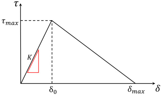
Figure 1.
Bilinear cohesive zone model.
is the critical bond strength, representing the maximum bond force that the interface can withstand before separation; is the critical displacement of the element at the time of failure, representing the maximum separation distance that can transmit the interface bond force, when , which means that the interface is completely debonding and the elements on both sides are separated; the area intersected by the curve and the horizontal axis is the interface fracture energy ; and is the tangent stiffness of the element before its degradation. The interface fracture energy , the bond strength , and the displacement are three important parameters of the cohesive zone model, and the relationship between them can be expressed as
The bilinear cohesive element has its judgment basis from damage initiation to damage evolution. The damage initiation criterion is used to determine when the damage begins to occur and when the stiffness begins to decay. In this paper, the maximum nominal stress criterion is selected as the initial initiation criterion, and the initial damage is satisfied as follows:
where and represent the actual stress values of the cohesive element perpendicular to and parallel to the crack direction, respectively; and and represent the maximum stress that can be borne perpendicular to the crack and parallel to the crack, respectively.
After the initial damage occurs, the damage evolution process follows. The damage evolution criterion in the cohesive zone model is used to express the relationship between the separation displacement and the traction force, and the degradation of its mechanical properties is characterized by stiffness degradation. Damage evolution can be expressed as
The stiffness degradation is represented by , and its value range is 0~1. If , it means that no damage has occurred; if , it means complete damage has occurred. After damage occurs, the stiffness of the element during the degradation is represented by :
2.2. Unified Phase-Field Theory
According to the existing research [25], in the process of steel fiber pull-out, not only does interface damage between the steel fiber and the concrete matrix lead to the fiber falling off, but the fiber falling off due to damage to the concrete matrix is the main damage form. To more intuitively and accurately characterize concrete matrix damage, this paper adopts the phase-field regularized cohesive zone model (PF-CZM), which was proposed based on the unified phase-field theory. The basic idea and main equations of the unified phase-field theory are briefly introduced below [26,30,32,33].
The reference configuration of a cracking solid, ( = 1, 2, 3), with a set of sharp cracks, , is shown in Figure 2a. In addition, the material particles of the solid are labeled by their spatial coordinates, ; thus, represents the displacement field of the solid and represents the strain field of the solid. The solid boundary is divided into two parts, and , which satisfies and . There is a displacement boundary condition, , at and a surface tractions boundary condition, , at . Thus, the displacement space can be expressed as
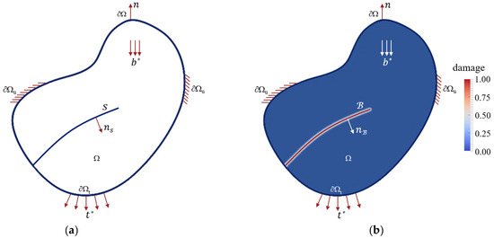
Figure 2.
Fracture diagram of the phase-field model: (a) sharp crack and (b) localized representation.
After the cracking solid is stressed, once the requirements of the cracking criterion are met, the sharp crack will occur in the solid. As shown in Figure 2b, in the phase-field method, the sharp crack will be regularized over a localization band, , there is a continuous damage field, , in the localization band, and there is no damage to the area outside the localization band. The damage space can be expressed as
where the derivative of damage to time represents the irreversibility of the damage.
2.2.1. Constitutive Relation and Damage Evolution Law
- (1)
- Constitutive relation
According to the first and second laws of thermodynamics, the energy dissipation inequality of the solid deformation process is as follows:
where represents the local free energy density of the solid, and considering the simplest isotropic case, the local free energy density can be expressed as the following general form:
where is the energy degradation function; is the initial strain energy density; is the effective stress tensor; and and are the elastic stiffness and compliance, respectively.
At this time, the driving force of the damage is given by
where is the effective damage driving force.
In summary, the following constitutive relation can be obtained:
- (2)
- Damage evolution law
Following Griffith’s fracture mechanics theory, the sharp cracks can be expressed as regularized cracks within the localization band :
According to the law of conservation of energy, there is the following relationship between the damage evolution of the localization band and the original sharp crack:
where is the fracture energy, usually regarded as a material property; is the crack surface density function, expressed as follows:
where the length scale characterizes the width of the localization band , which is an important parameter of the unified phase-field damage theory, and the geometric crack function determines the damage distribution in the localization band .
Based on the irreversibility of damage and Gauss’s divergence theorem, the damage evolution law can be obtained and its Neumann-type boundary conditions are as follows:
where is the outward normal of the boundary ; and is the derivative of the crack surface density function shown in Equation (14).
2.2.2. Phase-Field Regularized Cohesive Zone Model
There are two important characteristic functions in the unified phase-field damage theory, which are the geometric crack function , used to normalize the topology of physical cracks, and the energy degradation function , used to reflect the softening process of the material. Wu [26,30,32,33] combined the unified phase-field theory with the cohesive zone model, clarified the suggested values of the geometric crack function and the energy degradation function in practical applications, and then proposed the PF-CZM. The specific suggested forms are as follows:
where the coefficients , , and are derived from the following material:
where is the initial slope, is the length scale, and is the ultimate crack opening.
When and (i = 1, 2, 3) take specific values, the specific softening criterion can be fitted. The Cornelissen softening criterion [26,30,32,33] commonly used in concrete is adopted in this paper. It is calibrated according to the relevant test data of concrete and is most suitable for concrete materials. At this time, , , and .
2.2.3. Numerical Implementation
- (1)
- Governing equations
Based on the constitutive relations and damage evolution laws, the governing equations in strong form can be expressed as
and the following is the Neumann-type boundary condition:
Using the weighted residual method, the governing equations and boundary conditions can be transformed into the following weak forms:
where is the virtual work by the external force, and is the variation of the crack surface density function. The specific expression is as follows:
In conclusion, the unified phase-field damage theory starts from thermodynamics and transforms the complex structural damage problem and fracture mechanics problem into two governing equations, one for solving the displacement field problem and the other for solving the damage phase-field problem.
- (2)
- Finite element discretization
In the two-dimensional (2D) case, the calculation domain can be divided into meshes, , for discretization, and the superscript represents the mesh size of the finite element domain . It is worth noting that the mesh size should be much smaller than the localization bandwidth , which is generally taken as to ensure the accuracy of the calculation results. Each element node has three nodal degrees of freedom (dofs): two degrees of freedom of displacement and one degree of freedom of phase-field damage.
Based on the above settings, the displacement field and the strain field of the structure can be approximated by interpolation of the nodal displacements :
In the 2D case, the interpolation function matrix and the displacement–strain matrix at node are the following, respectively:
where is the interpolation function at node .
Similar to the discretization of the displacement field, the damage field and the damage gradient can be approximated by the interpolation of the node damage :
Accordingly, the interpolation function matrix and the displacement–strain matrix at node are the following, respectively:
With the above finite element discretization, the weak form (Equation (24)) can be transformed into a residual form of the equilibrium equation:
- (3)
- Solving algorithm
To solve the nonlinear algebraic equations system shown in Equation (29), this paper’s research is implemented using a user-defined subroutine. The user-defined subroutine is based on the corresponding interface of the finite element software, and the user writes the code according to the Fortran language. Based on the implementation of the user-defined subroutine [32], the PF-CZM achieves the simulation of the whole process of structural damage and destruction using the alternate minimization (AM) algorithm [34,35] of the above two control equations. The specific solution process is as follows (Figure 3):
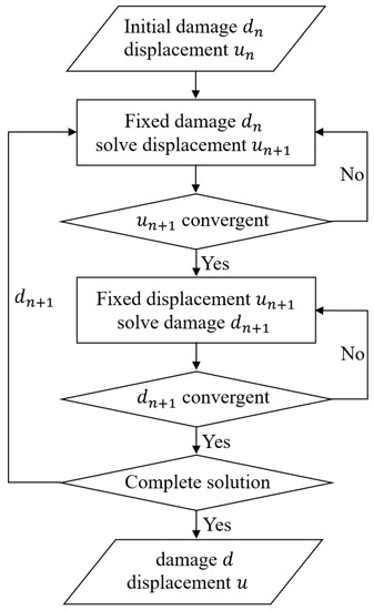
Figure 3.
Solution flow diagram.
3. Establishment and Verification of Numerical Calculation Model for Steel Fiber Pull-Out
3.1. Model Building
In this section, numerical simulations are carried out on the experiments conducted by Shannag et al. [9] to investigate the pull-out process of steel fiber; the schematic diagram and dimensions of the steel fiber pull-out specimen are shown in Figure 4a. The size of the concrete matrix is 23 mm × 25 mm, and the fiber diameter is 0.19 mm.
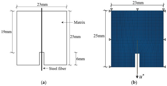
Figure 4.
The pull-out specimen of Shannag: (a) schematic diagram of the pull-out specimen and (b) finite element model of the pull-out specimen.
In this paper, ABAQUS finite element software was used to establish the numerical calculation model. For this finite element model, firstly, two parts of steel fiber and a concrete matrix are established, which are respectively assigned to different sets and assembled into one part. The concrete matrix part adopts the PF-CZM, and the CPS4T element is selected; the CPS4T is a four-node plane stress full-integration element with both displacement and temperature dofs built in; the steel fiber part adopts the bilinear cohesive zone model, and the CPS4R element is selected; the CPS4R is a four-node plane stress reduced-integration element, and when the steel fiber is bent and deformed, the linear reduced-integration element is selected to avoid the shear self-locking phenomenon. Then, the zero-thickness cohesive element is embedded between the two sets to represent the interface bond between the steel fiber and the concrete matrix. The cohesive element adopts the bilinear cohesive zone model, and the COH2D4 element is selected; the COH2D4 is the 2D cohesive element.
The steel fiber is subjected to a vertical downward concentrated force and restrained to vertical displacement on the upper side of the concrete matrix and horizontal displacement on both sides of the concrete matrix. The loading method adopts displacement loading, and the loading and restraint positions are shown in the 2D steel fiber pull-out finite element model shown in Figure 4b. The incorporated length scale parameter is b = 1 mm and the edge length of the quadrangle is h = 0.5 mm, and the 2D finite element mesh consists of 14,528 nodes and 14,211 quadrilateral linear elements.
The material parameters of the steel fiber and the concrete matrix were obtained from ref. [9], and the material parameters are shown in Table 1. The two parameters of the bond strength and fracture energy of cohesive elements in the interface layer are unknown in the finite element simulation, the parameters of the cohesive elements are determined using the trial calculation method, and the optimal parameters are determined by adjusting the two parameters of bond strength and fracture energy and comparing the pull-out load–displacement curves obtained by the numerical simulation with the experimental results.

Table 1.
Material parameters.
To investigate the influence of different factors on the mechanical properties of steel fiber pull-out during the steel fiber pull-out process and to consider the calculation efficiency of the model, the finite element model shown in Figure 5 is established in this paper. The size of the concrete matrix is 12.7 mm × 25.4 mm, and the fiber diameter is 0.5 mm. The model establishment, boundary conditions, and loading methods are the same as above. The finite element model of steel fiber pull-out vertical to the concrete matrix shown in Figure 5a is used to simulate and analyze the influence of different embedment depths, length–diameter ratios, and interface properties of steel fibers on the pull-out mechanical properties of steel fibers. The influence of different embedment angles of steel fibers on the pull-out mechanical properties of steel fibers is simulated and analyzed using the finite element model of steel fiber pull-out inclined to the concrete matrix shown in Figure 5b.

Figure 5.
The pull-out model of steel fiber: (a) geometric conditions and boundary conditions of steel fiber pull-out model and (b) pull-out model of steel fiber with inclination.
3.2. Model Validation and Analysis
Figure 6 shows the comparison between the pull-out load–displacement curve obtained from numerical simulation and the results of the steel fiber pull-out test in ref. [9], where the vertical axis is the vertical downward pull-out load applied to the steel fiber, and the horizontal axis is the relative displacement value of the steel fiber and the concrete matrix. When the bond strength of the cohesive element is taken as 0.5 MPa and the fracture energy is taken as 0.25 N/mm, the peak pull-out load obtained by the simulation is 10.148 N, the displacement corresponding to the peak pull-out load is 0.0187 mm, and the experiment results are 10.183 N and 0.0181 mm, with errors of 0.4% and 3.3%, respectively. Thus, the numerical simulation results are in good agreement with the experiment results.
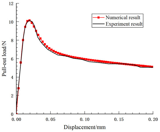
Figure 6.
Pull-out load–displacement curve.
It can be seen from Figure 6 that the numerical simulation results in this paper are in good agreement with the experiment results. The whole process of steel fiber pull-out can be roughly divided into four stages: in the first stage, the steel fiber is pulled at the beginning, and the pull-out load and the displacement grow linearly, while the steel fiber and the concrete matrix are in an elastic bond state; in the second stage, the increase in the pull-out load, the shear stress between the steel fiber and the concrete matrix reaches the interface bond strength, and the structure begins debonding, at which time the pull-out load and the displacement grow nonlinearly and increase to the maximum value; in the third stage, as the pull-out load continues to increase, the bonding area disappears, the steel fiber is completely debonding, and the occlusal force between the steel fiber and the concrete matrix gradually decreases; in the fourth stage, the pull-out load is completely borne by friction at this time and gradually decreases as the steel fiber is pulled out.
From this analysis, it can be seen that the finite element model established in this paper can better reflect the whole process of pulling out the steel fiber from the concrete matrix, which also shows that the model established in this paper has a certain accuracy and reliability.
4. Effects of Different Factors on the Mechanical Properties of Steel Fiber Pull-Out
4.1. Effect of Steel Fiber Embedment Depth
To investigate the influence of steel fiber embedment depth on the pull-out mechanical properties of steel fiber, finite element models with different steel fiber embedment depths of 6, 8, and 10 mm are established to simulate the pull-out process of steel fibers, as shown in Figure 5a. Other parameters are the same as above, and Figure 7 and Figure 8 show the pull-out load–displacement curves, peak pull-out load, and the displacement corresponding to the peak pull-out load for steel fibers with different embedment depths, respectively.
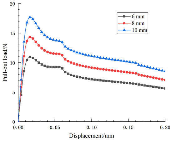
Figure 7.
Pull-out load–displacement curve of steel fiber with different embedment depths.
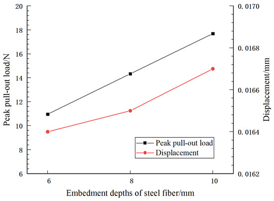
Figure 8.
Peak pull-out load and displacement of steel fiber with different embedment depths.
The results show that the distribution of the three groups of pull-out load–displacement curves is basically the same, and the ascending sections partially overlap, indicating that the embedment depth does not work before the steel fibers are debonding. With the increase in embedment depth, the contact area between the steel fiber and the concrete matrix increases, so the peak pull-out load also increases accordingly. The pull-out load-bearing capacities of steel fibers with embedment depths of 8 mm and 10 mm are 30.7% and 61.37%, respectively, these are higher than that of steel fibers with an embedment depth of 6 mm, which indicates that with the increase in the embedment depth of steel fiber, the pull-out load-bearing capacity of steel fiber increases greatly, and the displacement corresponding to the peak pull-out load also has a small increase. Therefore, the embedment depth of steel fiber significantly affects the mechanical properties of steel fiber pull-out.
4.2. Effect of Length–Diameter Ratio of Steel Fiber
The length and diameter of steel fibers are important dimensional parameters. To investigate the influence of the length–diameter ratio of the steel fiber on the mechanical properties of steel fiber pull-out, finite element models with steel fiber diameters of 0.5 mm, 0.2 mm, and 0.1 mm and an embedment depth of 6 mm are established to simulate the steel fiber pull-out process, as shown in Figure 5a. With all other parameters unchanged, the peak pull-out load and the displacement corresponding to the peak pull-out load for steel fibers with different length–diameter ratios are shown in Figure 9.
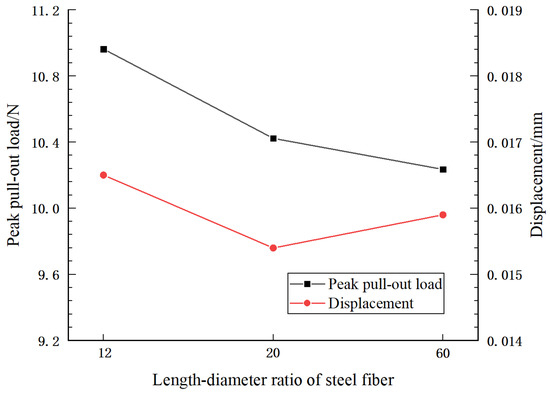
Figure 9.
Peak pull-out load and displacement of steel fibers with different length–diameter ratios.
It can be seen that with the same steel fiber embedment depth, the larger the diameter, the greater the pull-out force required to pull out the steel fibers. This also indicates that thicker steel fibers provide better reinforcement to steel fiber reinforced concrete. Therefore, steel fiber reinforced concrete with better mechanical properties can be obtained by using thick steel fiber in engineering practices. However, it is not the case that thicker steel fibers are always better; steel fibers that are too thick are not conducive to structural load-bearing and would affect the ductility and toughness of the structure [36].
4.3. Effect of Steel Fiber Embedment Angle
Steel fibers are randomly distributed in concrete materials, so they are mixed in concrete at different angles in practical engineering. To study the influence of the embedment angle of steel fibers on the mechanical properties of steel fiber pull-out, finite element models with different embedment angles of steel fibers, such as 0°, 15°, 30°, 45°, and 60°, are established and simulated as shown in Figure 5b. The displacement loads at all embedment angles are perpendicular to the concrete matrix surface and the embedment depth of the steel fibers is 10 mm.
The results shown in Figure 10 were obtained with only the embedment angle of the steel fibers changed. The simulation results show the following: (1) the magnitude of the peak pull-out load decreases with the increase in the embedment angle of the steel fiber; (2) the displacement corresponding to the peak pull-out load of steel fiber increases with the increase in the embedment angle of steel fiber. The numerical simulation results in this section are in agreement with the conclusions reached by Long X [19].
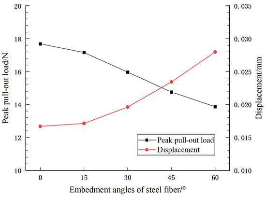
Figure 10.
Peak pull-out load and displacement of steel fiber with different embedment angles.
Figure 11 shows the stress diagram of steel fiber pulled out at 30°. Unlike the case in which the steel fibers are pulled out vertically from the concrete matrix, there is a certain contact pressure between the steel fiber and the left side of the matrix during the pull-out process when the steel fibers have an embedment angle. With the increase in the embedment angle of steel fibers, the pressure of steel fibers on the left side of the matrix increases and the matrix is deformed continuously, which leads to a crack between the steel fiber and the right side of the matrix; debonding occurs first, and the pull-out channel of the steel fiber changes. Thus, the pull-out load-bearing capacity of steel fiber decreases.
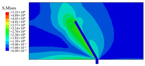
Figure 11.
Pull-out stress diagram of steel fiber.
4.4. Effect of Interface Properties
According to previous research, the debonding damage of the fibers pulled from the matrix mainly depends on the strength of the matrix itself and the strength of the interface layer between the fibers and the matrix. There are two main forms of damage: (1) when the bond strength between the fiber and the matrix is less than the load of the fiber pulled out, the interface between fiber and matrix will be damaged, resulting in fiber falling out, the interface between the fiber and the matrix is damaged, resulting in the fiber falling off; (2) when the bond strength between the fiber and the matrix is greater than the load that the fiber is pulled out of, the concrete matrix itself is damaged, which causes the fiber-bonded part of the concrete to fall off. In this section, the influence of interface properties on the mechanical properties of steel fiber pull-out is investigated using the finite element model with a steel fiber embedment depth of 6 mm, as shown in Figure 5a.
4.4.1. Failure of the Interface Layer between Steel Fiber and Concrete Matrix
When steel fiber reinforced concrete material is subjected to an external load, part of the stress of the concrete matrix is transferred to the steel fiber through the interface layer. Since the strength of steel fibers is much greater than the strength of the concrete matrix, whether the steel fibers play a role mainly depends on whether the interface layer fails. This section mainly studies the influence of the bond strength and fracture energy of the cohesive element of the interface layer on the mechanical properties of steel fiber pull-out.
- (1)
- Effect of bond strength
When analyzing the influence of interface bond strength on the mechanical properties of steel fiber pull-out, = 0.25 N/mm is taken as a certain value and is taken as 0.2 MPa, 0.5 MPa, 0.8 MPa, 1.1 MPa, and 1.4 MPa for five different groups of values, respectively, while all other parameters remain unchanged. The peak pull-out load and displacement corresponding to the peak pull-out load for steel fibers are obtained by numerical simulation, as shown in Figure 12.
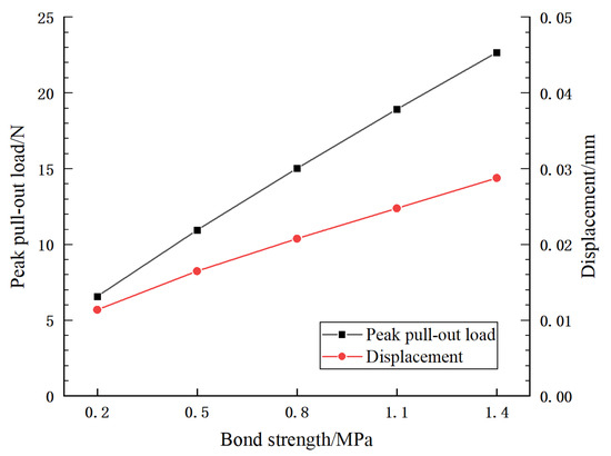
Figure 12.
Variation of peak pull-out load and displacement with interface bond strength.
The results show that when is 0.5~1.4 MPa, the pull-out capacity of steel fiber increases by 66.6~244.5% compared with 0.2 MPa. It can be seen that the peak tensile force increases greatly with the increase in interface bonding strength, and the reinforcement effect of steel fiber is better. This is because represents the stress value required to be reached by the interface element for the debonding between the steel fiber and the concrete matrix. Therefore, the higher the , the greater the load required for the debonding of the steel fiber. It can be seen that the bonding strength of the interface layer has a great influence on the mechanical properties of steel fiber pulled out from the concrete matrix. The bearing capacity of the member or structure can be effectively improved by enhancing the bonding strength of the interface layer.
- (2)
- Effect of fracture energy of the interface layer
To analyze the influence of the fracture energy of the cohesive element on the mechanical properties of steel fiber pull-out, = 0.5 MPa is taken as a certain value and is taken as 0.15, 0.25, 0.35, 0.45, and 0.55 N/mm for five different groups, respectively, while the other parameters remain unchanged. The peak pull-out load and displacement corresponding to the peak pull-out load for steel fibers are obtained by numerical simulation, as shown in Figure 13.
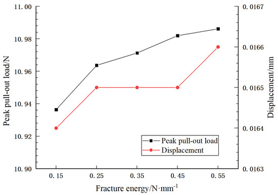
Figure 13.
Variation of peak pull-out load and displacement with interface fracture energy.
The results show that when takes 0.25~0.55 N/mm, the pull-out load-bearing capacity of steel fiber is increased by 0.24~0.46% compared with when takes 0.15 N/mm. Because the fracture energy represents the energy consumed by the debonding be-tween the steel fiber and the concrete matrix caused by the stiffness degradation of interface elements, the external load also increases with the increase in the load required” to “increases with the increase of , which increases the load required for the debonding between the steel fiber and the concrete matrix; that is, the bearing capacity of steel fiber reinforced concrete specimens is improved. However, according to the simulation results, the influence is much smaller than the influence of bonding strength on the pull-out performance of steel fibers, and the peak tensile strength increases gently.
4.4.2. Failure of the Concrete Matrix Itself
According to the scanning electron microscope image of the fiber damage form in ref. [25], it can be seen that the matrix’s damage is the main damage form for fiber pull-out. Therefore, in this section, it is assumed that the interface bond strength between steel fibers and the concrete matrix is high ( = 3 MPa) and no debonding damage occurs, and the influence of the mechanical properties of the concrete matrix itself on the mechanical properties of steel fiber pull-out is analyzed.
- (1)
- Effect of tensile strength
To analyze the influence of the tensile strength of concrete matrix material on the mechanical properties of steel fiber pull-out, = 0.25 N/mm is taken as a certain value and is taken as 1.9, 2.4, and 2.9 MPa for three different groups of values, respectively, while the other parameters remain unchanged.
When = 2.9 MPa and the steel fiber pull-out displacement is 0.1 mm, the damage distribution diagram of the model is shown in Figure 14. Damage is applied to CPS4T (concrete matrix) elements with values between 0 and 1, and when the value of damage is close to 1, it indicates that the element is damaged completely. It can be seen from Figure 14 that the damage in the localization zone of the crack evolves from 0 to 1, and the damaged part can basically be regarded as a real crack. From the damage diagram, it can be seen that the steel fibers carry part of the concrete to fall off in a conical shape at this time. Therefore, in terms of both appearance and specific values, the phase-field regularized cohesive zone model can accurately reflect the real physical cracks and is suitable for the study of steel fiber pull-out.
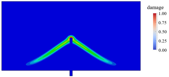
Figure 14.
Diagram of damage distribution.
The peak pull-out load and displacement corresponding to the peak pull-out load for steel fibers are obtained by numerical simulation, as shown in Figure 15. The results show that when the tensile strength is taken as 2.4 and 2.9 MPa, the pull-out load-bearing capacity of steel fiber is increased by 20.84 and 40.43%, respectively, compared with when takes 1.9 MPa. It can be seen that the peak pull-out load increases with the increase in the tensile strength of the matrix, and the corresponding displacement of the peak pull-out load also increases slightly. It is also suggested that the bearing capacity of steel fiber reinforced concrete can be improved by improving the strength of concrete in engineering practices.
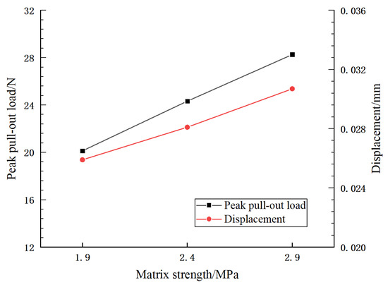
Figure 15.
Variation of peak pull-out load and displacement with matrix strength.
- (2)
- Effect of fracture energy of the concrete matrix
To analyze the influence of the fracture energy of concrete matrix material on the mechanical properties of steel fiber pull-out, = 2.9 MPa is taken as a certain value and is taken as 0.15, 0.25, and 0.35 N/mm for three different groups of values, respectively, while the other parameters remain unchanged; the numerical simulation results are shown in Figure 16.
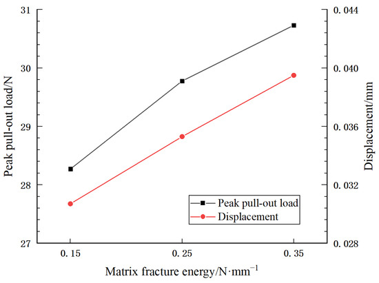
Figure 16.
Variation of peak pull-out load and displacement with matrix fracture energy.
The results show that when the fracture energy is taken as 0.25 and 0.35 N/mm, the pull-out load-bearing capacity of steel fiber is increased by 5.3 and 8.7%, respectively, compared with when takes 0.15 N/mm. It can be seen that the peak pull-out load increases with the increase in the fracture energy of the matrix material and the corresponding displacement of the peak pull-out load can also increase slightly. Therefore, the bearing capacity of steel fiber reinforced concrete can be improved by increasing the fracture energy of the concrete matrix material.
5. Conclusions
At present, steel fiber reinforced concrete is widely used in civil engineering because of its excellent mechanical properties, but there are still many problems to be studied in terms of the damage, fracture failure mechanism, and evolution process of steel fiber reinforced concrete. The pull-out test and numerical simulation of concrete specimens containing single steel fibers are important means for investigating the bond strength of the interface between the steel fibers and the concrete. Compared with related published numerical simulation work, this paper adopts the newly proposed unified phase-field theory, which has the following advantages in the characterization of concrete materials: it can accurately describe the formation, propagation, and bifurcation of cracks; there is no stress oscillation, which makes it easy to implement numerically; and the grid has low sensitivity, which can ensure high calculation accuracy. This paper calculates and analyzes the influences of different factors and different failure forms on the steel fiber pull-out process, and can thus provide a more comprehensive and in-depth study on the bonding properties of the interface between steel fibers and concrete. The following main conclusions are drawn:
- (1)
- Based on the cohesive zone model and the unified phase-field theory, the pull-out load–displacement curve obtained by the simulation of the steel fiber pull-out test is in good agreement with the test results, which indicates that the finite element model of steel fiber pull-out established by the cohesive zone model and the phase-field regularized cohesive zone model has a certain accuracy and reliability. In addition, according to the results, the phase-field regularized cohesive zone model can represent the damage and failure evolution process of a concrete matrix intuitively and accurately.
- (2)
- By studying the influence of different factors on the pull-out mechanical properties of steel fiber, it is found that the pull-out load-bearing capacity of steel fiber when the embedment depth of steel fiber is 8mm and 10mm is increased by 30.7 and 61.37%, respectively, compared with that when the embedment depth is 6 mm. However, the pull-out load-bearing capacity of steel fiber is reduced with the increase in the length–diameter ratio and the embedment angle of the steel fiber. Therefore, these factors can be adjusted in actual projects to achieve the purpose of improving the mechanical properties of steel fiber reinforced concrete.
- (3)
- By studying the influence of interface properties on the pull-out mechanical properties of steel fiber, it is found that the bond strength of the interface layer and the strength of the concrete matrix have great influences on the pull-out mechanical properties of steel fiber. Among these influences, when the interface bond strength is 0.5~1.4 MPa, the pull-out load-bearing capacity of steel fiber is increased by 66.6~244.5% compared with 0.2 MPa; and when the matrix strength is 2.4 and 2.9 MPa, the pull-out load-bearing capacity of steel fiber is increased by 20.84 and 40.43%, respectively, compared with that when the matrix strength is 1.9 MPa. Therefore, the reinforcing effect of steel fiber on the concrete matrix can be improved by controlling the bond strength of the interface layer and the strength of the concrete matrix.
Considering factors such as computational resources and costs, numerical simulations were conducted in this paper for only a 2D finite element model of steel fiber reinforced concrete. The 3D finite element model should be able to reflect the steel fiber pull-out test more realistically and comprehensively. Therefore, future efforts could establish the 3D and meso-level finite element models based on unified phase-field theory under all kinds of conditions.
Author Contributions
Conceptualization, H.W.; methodology, H.W.; software, G.W.; formal analysis, H.W. and G.W.; data curation, G.W.; writing, G.W. and H.W. All authors have read and agreed to the published version of the manuscript.
Funding
This research was funded by the National Natural Science Foundation of China [51568062] and also by the Natural Science Foundation of Xinjiang Uygur Autonomous Region [2016D01C063].
Institutional Review Board Statement
Not applicable.
Informed Consent Statement
Informed consent was obtained from all subjects involved in the study.
Data Availability Statement
The data used to support the findings of this study are included within the article.
Conflicts of Interest
The authors declare that there are no conflict of interest.
References
- Yao, J.; Zhou, Z.; Zhou, H. Steel Fiber Reinforced Concrete. In Highway Engineering Composite Material and Its Application; Springer: Singapore, 2019; pp. 51–80. ISBN 9789811360671. [Google Scholar]
- Gilbert, R.I.; Bernard, E.S. Post-cracking ductility of fibre reinforced concrete linings in combined bending and compression. Tunn. Undergr. Space Technol. 2018, 76, 1–9. [Google Scholar] [CrossRef]
- De Smedt, M.; Vrijdaghs, R.; Van Steen, C.; Verstrynge, E.; Vandewalle, L. Damage analysis in steel fibre reinforced concrete under monotonic and cyclic bending by means of acoustic emission monitoring. Cem. Concr. Compos. 2020, 114, 103765. [Google Scholar] [CrossRef]
- Abdulhameed, H.A.; Nassif, H.; Khayat, K.H. Use of Fiber-Reinforced Self-Consolidating Concrete to Enhance Serviceability Performance of Damaged Beams. Transp. Res. Rec. 2018, 2672, 45–55. [Google Scholar] [CrossRef]
- Vijayan, D.S.; Sivasuriyan, A.; Parthiban, D.; Jakimiuk, A.; Bayat, H.; Podlasek, A.; Vaverková, M.D.; Koda, E. A Comprehensive Analysis of the Use of SFRC in Structures and Its Current State of Development in the Construction Industry. Materials 2022, 15, 7012. [Google Scholar] [CrossRef]
- Naaman, A.E.; Najm, H. Bond-Slip Mechanisms of Steel Fibers in Concrete. Aci Mater. J. 1991, 88, 135–145. [Google Scholar]
- Tuyan, M.; Yazıcı, H. Pull-out behavior of single steel fiber from SIFCON matrix. Constr. Build. Mater. 2012, 35, 571–577. [Google Scholar] [CrossRef]
- Bhutta, A.; Farooq, M.; Zanotti, C.; Banthia, N. Pull-out behavior of different fibers in geopolymer mortars: Effects of alkaline solution concentration and curing. Mater. Struct. 2017, 50, 80. [Google Scholar] [CrossRef]
- Shannag, M.J.; Brincker, R.; Hansen, W. Pullout behavior of steel fibers from cement-based composites. Cem. Concr. Res. 1997, 27, 925–936. [Google Scholar] [CrossRef]
- Abu-Lebdeh Rate Effect on Pullout Behavior of Steel Fibers Embedded in Very-High Strength Concrete. Am. J. Eng. Appl. Sci. 2010, 3, 454–463. [CrossRef]
- Abu-Lebdeh, T.; Hamoush, S.; Heard, W.; Zornig, B. Effect of matrix strength on pullout behavior of steel fiber reinforced very-high strength concrete composites. Constr. Build. Mater. 2011, 25, 39–46. [Google Scholar] [CrossRef]
- Kim, J.-J.; Yoo, D.-Y. Effects of fiber shape and distance on the pullout behavior of steel fibers embedded in ultra-high-performance concrete. Cem. Concr. Compos. 2019, 103, 213–223. [Google Scholar] [CrossRef]
- Ye, D.J.; Yang, Z.J.; Liu, G.H.; Yao, Y. Analytical Solution and Experimental Verification of Pullout Force of Twisted Steel Fibers in Ultra–high Performance Concrete. J. Zhejiang Univ. (Eng. Sci.) 2018, 52, 1911–1918. (In Chinese) [Google Scholar]
- Lee, Y.; Kang, S.-T.; Kim, J.-K. Pullout behavior of inclined steel fiber in an ultra-high strength cementitious matrix. Constr. Build. Mater. 2010, 24, 2030–2041. [Google Scholar] [CrossRef]
- Wang, X.W.; Guo, R.; Tian, W.; Zhao, X. Experimental Investigation of the Bonding and Slipping Performance of the Deformed Steel-fiber. J. Hebei Univ. Technol. 2007, 36, 110–114. (In Chinese) [Google Scholar]
- Tian, W.L.; Wang, X.W.; Li, Z.X. Research on the Experiment of the Bonding Strength between Deformed Steel Fiber and Concrete. J. Build. Mater. 2007, 10, 337–341. (In Chinese) [Google Scholar]
- Shao, W.; Sun, Q.; Xu, X.; Yue, W.; Shi, D. Durability life prediction and horizontal bearing characteristics of CFRP composite piles in marine environments. Constr. Build. Mater. 2023, 367, 130116. [Google Scholar] [CrossRef]
- Wang, H.; Li, L.; Li, J.; Sun, D. Drained expansion responses of a cylindrical cavity under biaxial in situ stresses: Numerical investigation with implementation of anisotropic S-CLAY1 model. Can. Geotech. J. 2023, 60, 198–212. [Google Scholar] [CrossRef]
- Long, X. Numerical Simulation of the Fiber Pulled Out from Steel-fiber Concrete. Master's Thesis, Northeastern University, Shenyang, China, 2014. (In Chinese). [Google Scholar]
- Hsueh, C.-H. Interfacial Debonding and Fiber Pull-out Stresses of Fiber-reinforced Composites. Mater. Sci. Eng. A 1990, 123, 1–11. [Google Scholar] [CrossRef]
- Kim, J.; Baillie, C.; Mai, Y. Interfacial debonding and fibre pull-out stresses. J. Mater. Sci. 1992, 27, 3143–3154. [Google Scholar] [CrossRef]
- Huang, J.; Jiang, H.D.; Mei, M.R. Analysis of Fiber Debonding and Pull-out with Interfacial Layer. J. Yangtze River Sci. Res. Inst. 2006, 23, 61–64. (In Chinese) [Google Scholar]
- Liu, F. Study of Numerical Simulation for Steel Fiber Reinforced Concrete on Meso-Level. Master's Thesis, South China University of Technology, Guangzhou, China, 2014. (In Chinese). [Google Scholar]
- Zong, Y.W. Analysis of Interfacial Bonding Properties of Cement-based Materials with Steel Fibers Based on Cohesive Zone Model. Master's Thesis, Chongqing University, Chongqing, China, 2017. (In Chinese). [Google Scholar]
- Yang, C.C. Numerical Simulation of the Influence of Basalt Fiber on the Performance of Asphalt Mixture. Master's Thesis, Changsha University of Science & Technology, Changsha, China, 2020. (In Chinese). [Google Scholar]
- Wu, J.-Y. A geometrically regularized gradient-damage model with energetic equivalence. Comput. Methods Appl. Mech. Eng. 2018, 328, 612–637. [Google Scholar] [CrossRef]
- Zhuang, L.J. Application Study of Unified Phase Field Theory for Modeling Localized Failure in Concrete. Master's Thesis, South China University of Technology, Guangzhou, China, 2019. (In Chinese). [Google Scholar]
- Wu, J.-Y.; Qiu, J.-F.; Nguyen, V.P.; Mandal, T.K.; Zhuang, L.-J. Computational modeling of localized failure in solids: XFEM vs PF-CZM. Comput. Methods Appl. Mech. Eng. 2019, 345, 618–643. [Google Scholar] [CrossRef]
- Yang, Z.-J.; Li, B.-B.; Wu, J.-Y. X-ray computed tomography images based phase-field modeling of mesoscopic failure in concrete. Eng. Fract. Mech. 2019, 208, 151–170. [Google Scholar] [CrossRef]
- Wu, J.-Y. A unified phase-field theory for the mechanics of damage and quasi-brittle failure. J. Mech. Phys. Solids 2017, 103, 72–99. [Google Scholar] [CrossRef]
- Lu, Z.X. A Simple Review for Cohesive Zone Models of Composite Interface and Their Applications. Chin. J. Solid Mech. 2015, 36 (Suppl. S1), 85–94. (In Chinese) [Google Scholar]
- Wu, J.-Y.; Nguyen, V.P. A length scale insensitive phase-field damage model for brittle fracture. J. Mech. Phys. Solids 2018, 119, 20–42. [Google Scholar] [CrossRef]
- Wu, J.-Y.; Huang, Y. Comprehensive implementations of phase-field damage models in Abaqus. Theor. Appl. Fract. Mech. 2020, 106, 102440. [Google Scholar] [CrossRef]
- Bourdin, B.; Francfort, G.A.; Marigo, J.-J. Numerical experiments in revisited brittle fracture. J. Mech. Phys. Solids 2000, 48, 797–826. [Google Scholar] [CrossRef]
- Bourdin, B.; Francfort, G.A.; Marigo, J.J. The Variational Approach to Fracture; Springer Science & Business Media: Cham, Switzerland, 2008. [Google Scholar]
- Zhang, H.; Huang, Y.J.; Yang, Z.J.; Xu, S.L.; Chen, X.W. A discrete-continuum coupled finite element modelling approach for fibre reinforced concrete. Cem. Concr. Res. 2018, 106, 130–143. [Google Scholar] [CrossRef]
Disclaimer/Publisher’s Note: The statements, opinions and data contained in all publications are solely those of the individual author(s) and contributor(s) and not of MDPI and/or the editor(s). MDPI and/or the editor(s) disclaim responsibility for any injury to people or property resulting from any ideas, methods, instructions or products referred to in the content. |
© 2023 by the authors. Licensee MDPI, Basel, Switzerland. This article is an open access article distributed under the terms and conditions of the Creative Commons Attribution (CC BY) license (https://creativecommons.org/licenses/by/4.0/).