Article

Effects of Upward Reflective Film Applied to Window Glass on Indoor and Outdoor Thermal Environments in a Mid-Latitude City

Urban Environmental Engineering Laboratory, Kobe University, Kobe 657-8501, Japan
*
Author to whom correspondence should be addressed.
Sustainability 2023, 15(4), 3848; https://doi.org/10.3390/su15043848
Submission received: 24 December 2022 / Revised: 10 February 2023 / Accepted: 16 February 2023 / Published: 20 February 2023
(This article belongs to the Special Issue Urban Heat Island and Building Energy Sustainability)

Abstract

:
The effect of upward reflective film applied to a window on the thermal environment inside and outside the window was investigated, considering the reflection and transmission characteristics depending on the angle of incident solar radiation. In terms of controlling the amount of solar radiation on a building’s windows, it is sufficient if the reflected solar radiation returns upward and does not need to be retroreflected in the azimuthal direction. Therefore, in this study, only the incident angle was considered and treated in two dimensions. The amount of incident solar radiation on the vertical façade is greater around 9:00 and around 16:00. Therefore, it is important to take measures in the morning for east-facing windows and in the afternoon for west-facing windows. The indoor MRT in front of upward reflective film is lower than in front of a transparent window due to lower transmittance. The outdoor MRT in front of upward reflective film is suppressed to the same level as in front of a transparent window, because the downward reflectance does not increase as much as in transparent windows. Upward reflective films applied to windows can improve the indoor thermal environment without worsening the outdoor thermal environment compared to thermal barrier films.

1. Introduction

The short-wave and infrared radiation reflected and emitted by the façade may fall on other walls and road surfaces, causing high temperatures through the process of multiple reflection and absorption. Reflected solar radiation may fall on walls or road surfaces, but increasing the reflectance of those surfaces can reduce the high temperature of the city. In the case of diffuse reflection, there are a few adverse effects, but in the case of specular reflection, such as on glass surfaces, it is assumed that there may be adverse effects on pedestrians [1]. Therefore, careful consideration should be given to the introduction of high-reflectance technologies. Takebayashi [2] studied the guidelines for introducing highly reflective technology to facades, using the number of stories of the facade and the distance from the building to the walking space as indicators. The following conclusions were drawn. In Japanese cities located at mid-latitudes, when highly specular reflective technology is applied to the facades on the fourth floor and above, the downward reflected solar radiation reaches the roadway in the middle of the street and does not adversely affect people on either side of the street. Upward reflective technology was considered for use in building façades below the third floor to avoid impact on pedestrians from the downward reflection of solar radiation.
Several studies on upward-reflective technology have already reported the properties and effectiveness of retroreflective materials. Yuan et al. [3] evaluated the durability of retroreflective materials during long-term outdoor exposure and estimated their retroreflectance using a spectrophotometer and the heat balance calculated from outdoor temperatures. Yuan et al. [4] also evaluated the albedo, cooling, and heating loads for an urban canyon with retroreflective materials. Yuan et al. [5,6] evaluated the retroreflectance of these materials using an emitting–receiving optical fiber system. Rossi et al. [7] experimentally measured the angular reflectance of retroreflective materials and compared their measurements with those obtained using an equation devised for evaluating angular reflectance based on diffuse reflection. Another study [8] measured the angular reflectance of several types of retroreflective materials and evaluated the energy subsequently entrapped in an urban canyon, at various latitudes and on various days. Rossi et al. [9] further evaluated the urban heat island mitigation potential of retroreflective pavements in urban canyons through an experiment in an existing small-scale urban canyon. Castellani et al. [10] developed new ceramic tiles for outdoor applications with appropriate treatment to obtain retroreflective optical properties. Measurement and calculation methods for determining the angular reflection from building materials have been studied by Ichinose et al. [11,12], Nakaohkubo et al. [13], Nishioka et al. [14,15], and Yoshida et al. [16].
In Japan, the Japanese Industrial Standard (JIS) has been established for measuring the retroreflectance of adhesive films for glazing (JIS A 1494, Measurement methods for performance of solar radiation retroreflectivity on adhesive films for glazings [17]). The details of JIS A 1494 follow the results of Harima et al. [18,19]. The Osaka Heat Island Countermeasure Technology Consortium (Osaka HITEC) certifies retroreflective materials as an effective technology for heat island countermeasures based on the following certification requirements [20]. The reflectance of solar radiation reflected above a line perpendicular to the vertical facade is defined as upward reflectance, and the reflectance of solar radiation reflected below is defined as downward reflectance. On opaque walls, the upward reflectance was 40% or more, and the downward reflectance was 30% or less. On window surfaces, the upward reflectance was 10% or more, and the downward reflectance was 10% or less. The standards for window surfaces installed for viewing and lighting were lower than those for walls. Fox et al. [21] stated that not much research has been conducted on the microclimate impacts of urban vertical surfaces, and the effects of building façade geometry and the fabric of building facades. They also described a reflectance recovery method applied to a multispectral image panorama of a sampled building façade to create a reflectance dataset for input into a probabilistic model.
Ichinose et al. [12] compared the effects of clear, clear + film (heat-shielding film), clear + retroreflective film, and low-E (low-E double glazing) on the heat load of a south-facing façade with a 60% window area in an office in Tokyo. They stated that the clear + retroreflective film has the same cooling load reduction effect as the clear + film, but the annual energy-saving effect is smaller than that of low-E because of the increased heating load. The amount of upwardly reflected solar radiation with the clear + retroreflective film increased by approximately 5% compared to the clear and low-E films, and the amount of downwardly reflected solar radiation was almost the same as that of the clear film; however, the reflectance of a 60-degree angle of incident solar radiation on the window was used for the study. Levinson et al. [22] developed performance parameters for solar retroreflective walls by evaluating the angular distribution of solar radiation incident on exterior walls in 17 climates in the United States, and applied first-principles physics and ray-tracing simulations to investigate the design. According to their analysis, for retroreflective walls to reflect a significant portion of summer solar radiation, they must function at a large angle of incidence, which is difficult to achieve with materials that rely on total internal reflection. Yuan et al. [23] analyzed the variation of retroreflective properties of glass bead retroreflectors with incidence angle, and pointed out that it is necessary to analyze the properties of retroreflectors by considering the azimuth angle as well as the solar altitude angle. Ichinose et al. [12] quantitatively demonstrated the advantages of using retroreflective films on the vertical facades of high-rise buildings by conducting measurements using an integrating sphere on the window surfaces of actual buildings and in a laboratory.
The control of solar radiation on glass surfaces is an important theme in this field, and it is important to evaluate the applicability of retroreflective films, which have been proposed as a new technology, in actual buildings by comparing them with existing thermal barrier films. Harima et al. [18,19] mainly discussed the south side of the building, assuming a summer season with a high solar altitude angle in the northern hemisphere; however, the evaluation of the east–west side of the building in early autumn with a low solar altitude angle, considering the indoor side demand, is not clear. The purpose of this study is to comprehensively evaluate the impact of an upward reflective film on the thermal environment inside and outside windows from a practical standpoint, based on calculations and measurement results, taking into account the reflectance data from the angle of incidence using integrating spheres conducted by Harima et al. and based on JIS A 1494, and the reflection and transmission characteristics of solar radiation according to the angle of incidence. Since this project aims for social implementation, the number of measurements were limited due to operational constraints, as the measurements were conducted in an operational building. In addition, because of the installation conditions of the film and measurement limitations, three-dimensional measurements were difficult. Therefore, we prepared feasible measurement conditions and combined them with simulation studies. The east and west sides were chosen for evaluation, especially considering the need for countermeasures indoors and in early autumn when the solar altitude angle is lower than that in summer.

2. Calculation Methods and Measurement Conditions

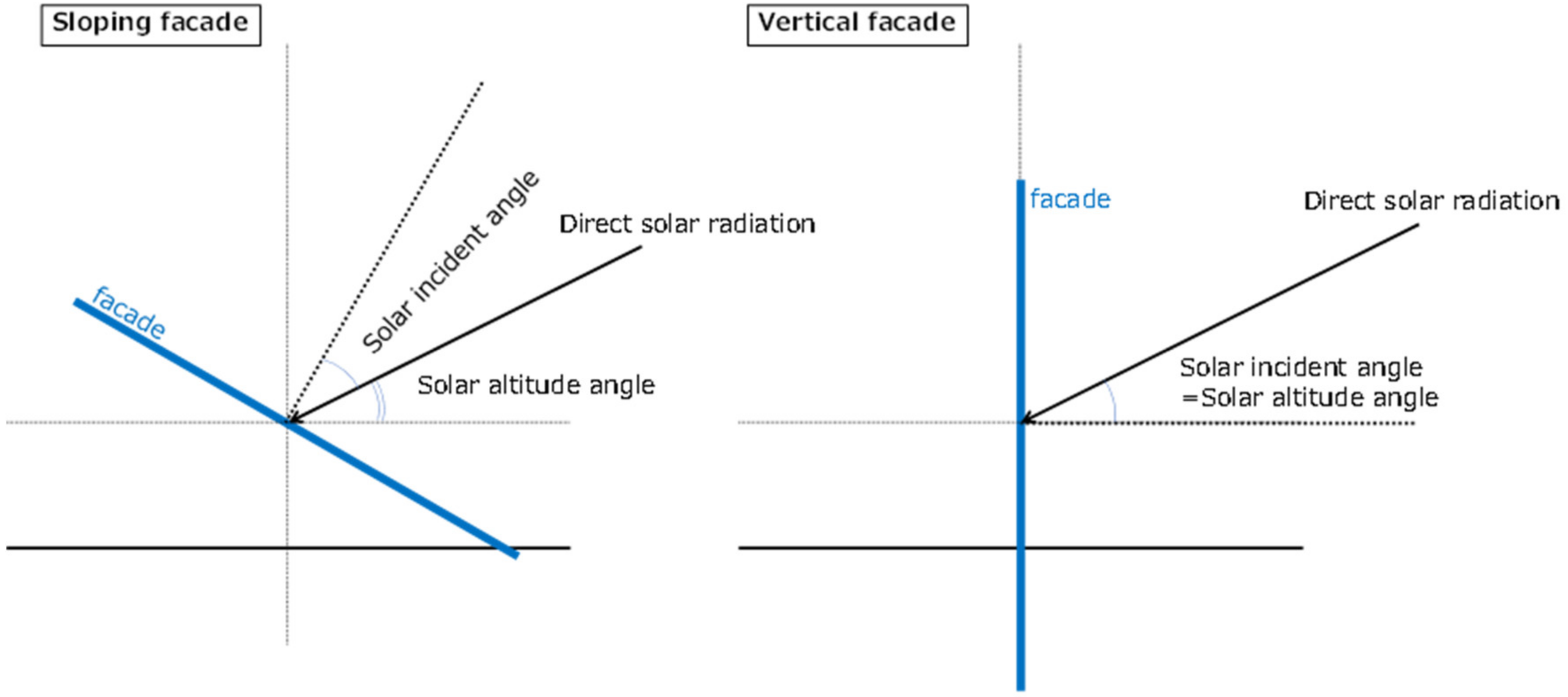
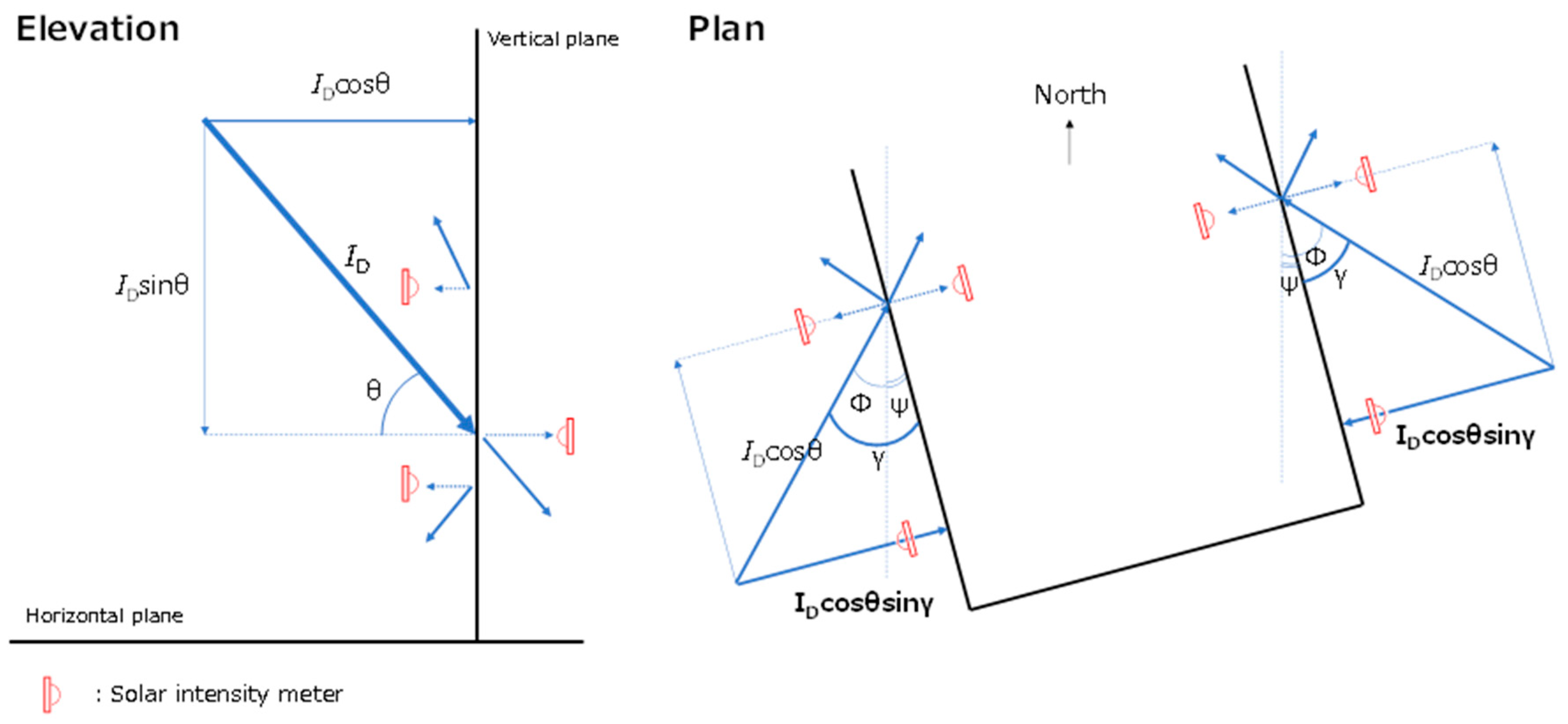
2.1. Calculation of Solar Radiation and Window Surface Heat Balance and MRT

In addition to direct solar radiation, diffuse and reflected solar radiation are incident on the surface of a window; however, direct solar radiation dominates on sunny days. The visibility coefficient from the vertical plane to the sky was less than 0.5, and was especially small in urban areas. The effects of reflected solar radiation from the opposing facades and the ground surface are manifold. When the ratio of direct solar radiation is small and diffuse solar radiation is dominant, the total amount of solar radiation is small. Therefore, it was decided that diffuse solar radiation and reflected solar radiation would not be considered in this study, as they are not prioritized in terms of the heat countermeasures required by the city of Kobe.
As shown in Figure 1, in this study, only the case in which the facade is 90° to the horizontal plane is treated; so, for convenience, solar incidence angle = solar altitude angle.
Figure 2 shows the concept of the solar radiation components measured in this study. Although it is desirable to install pyranometers in a position wherein incident solar radiation, vertically reflected solar radiation, and transmitted solar radiation enter the building vertically, it is difficult to move the pyranometers to follow the angle of solar radiation, which changes over time, in actual measurements in an operational building. Therefore, we decided to install the pyranometers parallel to the windows. This measurement method assumes that the smaller the γ (the difference between the solar azimuth angle Φ and the surface azimuth angle ψ), that is, the closer to the time of sunrise and sunset, the larger the error.
The direct normal irradiance ID is expressed by Bouguer’s equation as follows:
ID = J_0 P(1/sinθ)
where J_0 is the solar constant and P is the atmospheric transmittance, assumed to be 1353 [W/m2] and 0.7, respectively.
The direct solar radiation incident perpendicular to the window surface, IDcosθsinγ, and the reflected, transmitted, and absorbed direct solar radiation, IDdownref, IDtrans, and IDabs [W/m2], are expressed as follows:
IDcosθsinγ= ID · cosθsinγ
IDdownref = IDcosθsinγρdown
IDtrans = IDcosθsinγτ
IDabs = IDcosθsinγα
ρdown, τ, and α are the downward reflectance, transmittance, and absorptance, respectively.
In the calculation, the reflectance and transmittance of the retroreflective and thermal barrier films were measured by Dexerials using an integrating sphere, light source, and spectrophotometer according to JIS A1494, and the reflectance and transmittance of single-plate glass were measured by AGC. The measurement results in Chapter 3 show that the field measurement results are overlaid on the calculation results. The upward reflectance ρup_m, downward reflectance ρdown_m, and transmittance τm were calculated based on the measurement results, using the following equation:
ρup_m = Jup/Jin
ρdown_m = Jdown/Jin
τm = Jtrans/Jin
Jin, Jup, Jdown, and Jtrans are the incident, upward, downward, and transmitted solar radiation [W/m2], respectively.
The film used in this study is retroreflective for the vertical angle of incidence corresponding to the solar altitude angle, but not for the horizontal angle; therefore, it reflects upward but is not completely retroreflective to the sun. To control the amount of solar radiation on a building’s windows, it is sufficient if the reflected solar radiation returns upward and does not need to be retroreflected in the azimuthal direction. Therefore, in this study, we did not consider the solar azimuth angle but only the solar altitude angle. The film used in this study is henceforth described as an upward reflective film. We did not track how far away from the building the reflected solar radiation has an affect; we only tracked direct solar radiation incident on the facade, and whether the window is on the south, east, or west side.
A simple model of the heat balance at the surface of the glass window was assumed.
Long-wavelength radiation is calculated using the total heat transfer coefficient [W/(m2K)], which integrates convective and radiative heat transfer.
The heat balance of the window surface, considering only the direct solar radiation, is calculated as follows:
ID,abs = aout (TsTa) + ain (TsTin)
Ts = (ID,abs + aoutTa + ain Ta)/(aout + ain)
The mean radiant temperature in outdoor space is calculated as follows:
MRTout = (((ID + ID,downref)/4 + ∑ϕiσTi4)/σ))1/4 − 273.15   (i = 1 to 4)
The mean radiant temperature in indoor space is calculated as follows:
MRTin = ((ID,trans/4 + ∑ϕiσTi4)/σ))1/4 − 273.15  (i = 1 to 4)
where Ts, Ta, and Tin are the glass surface, outdoor temperature, and indoor temperature [°C], respectively. aout and ain are the outdoor and indoor total heat transfer coefficients [W/(m2K)], where aout and ain are assumed to be [28 W/(m2K)] (convection: 23, radiation: 5) and 14 [W/(m2K)] (convection: 9, radiation: 5), respectively. ϕi is the view factor [-], which is assumed 0.25 each for (1) windows, (2) sky/ceiling, (3) floor/ground, and (4) walls. Ti is surface temperature [K]; to discuss the effect of changes in the window surface temperature Ts on the indoor and outdoor MRT, the ambient temperatures of the outdoor ground surface, walls, trees, and sky were assumed to be equal to the outdoor air temperature Ta, and the ambient temperatures of the indoor floor surface, walls, and ceiling surface were assumed to be equal to the room temperature Tin. σ is the Stefan–Boltzmann constant (=5.67 ∗ 10−8) [W/(m2K4)]. The observed values at the Kobe meteorological observatory are given for Ta and 26 °C, which are typical in Japan and assumed for the air-conditioned Tin.

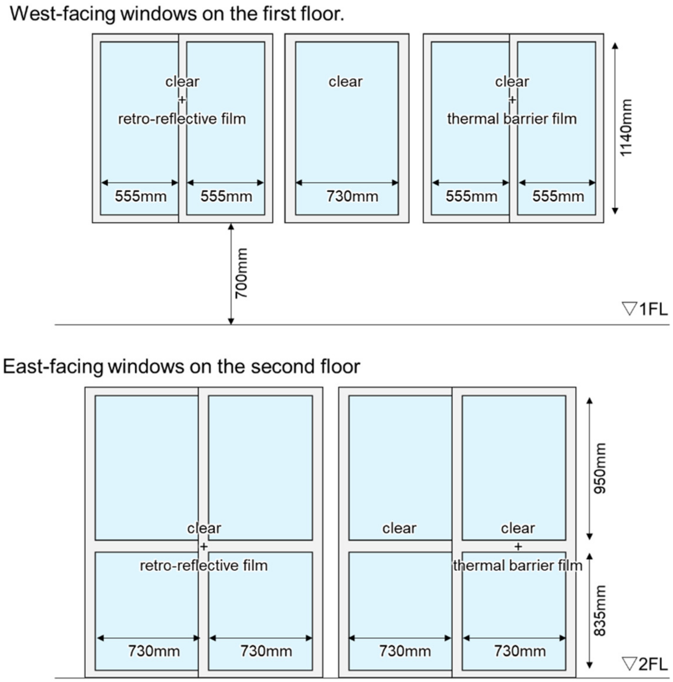
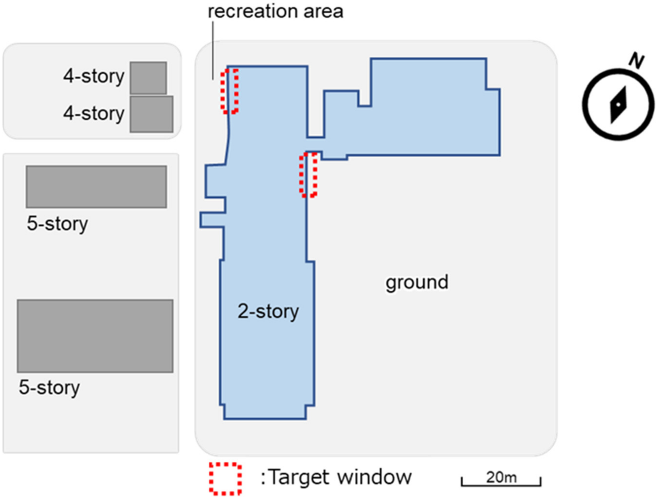
2.2. Measurement Conditions

An upward reflective film and thermal barrier film were applied to the east and west window surfaces of a building in Kobe, located at 34°41′ N and 135°10′ E. These correspond to the clear + retroreflective film and clear + film in the study by Ichinose et al. [12]. Figure 3, taken from the study by Harima et al. [19], shows a schematic diagram of the retroreflective film attached to the back of the float glass, showing transmitted visible light and upwardly reflected infrared light [19]. The upward reflective film (developed by Harima et al.) used in this study, which is available in the markets in Japan and other countries, has a two-dimensional reflective structure. For both the upward reflective film and thermal barrier film, the film was applied to the interior side of the glass.
Pyranometers were installed on the outside and inside of the window, 30 cm from the window surface, to measure incident, reflected, and transmitted solar radiation. Upward and downward reflected solar radiation was measured by covering the pyranometer according to the method described by Ichinose et al. [12]. Because the size of the glass window was not very large (width 555–730 × height 835–1200 mm), the pyranometer was moved to take measurements to avoid its influence. The reflected solar radiation was first measured for each window (at three locations) outdoors, and then it was moved indoors to measure the transmitted solar radiation for each window. The incident solar radiation was measured continuously, without moving, during the reflected and transmitted measurements. Figure 4 shows the size of the window and the application of the film, as observed indoors. Measurements were performed on 10 September and 6 October 2021. Although Harima et al. [18,19] discussed the summer season when the solar altitude angle is high, we focused on the early autumn season when the solar altitude angle is lower than the summer season and heat measures are needed (considering the demand on the indoor side, where direct solar radiation reaches) and the thermal environment is likely to worsen. Measurements were taken on the east face in the morning (7:30–11:00 on the clock) and on the west face in the afternoon (13:00–17:00–clock). The measurement targets were the east-facing windows on the second floor and the west-facing windows on the first floor. The measured buildings and their surroundings are shown in Figure 5. There is ground on the other side facing east, a small recreational area with benches and trees on the other side facing west, and a building across the street. An upward reflective film was introduced to avoid reflected solar radiation on players in the field and people resting in the recreational area. An overview of the measurements is shown in Figure 6. The pyranometer was installed at a position in which it could capture the reflected and transmitted solar radiation according to the solar altitude and azimuth angles. The incident solar radiation minus the amount of transmitted and reflected radiation was treated as absorbed solar radiation. The measurements were carried out when the weather was as clear as possible, but clear and cloudy weather sometimes interchanged over short periods. In such cases, the measurement time was extended, but the average values of the measured solar radiation discussed in Chapter 3 include the dispersion between cloudy and sunny periods. The indoor globe sphere was placed at a height of 1200 mm when measuring the west window, and 900 mm when measuring the east window, assuming seating conditions. The difference in height was due to installation constraints. Outdoors, the height of the globe sphere was set at 1500 mm for both the east and west windows, assuming that people stood. The measurement height of the thermo-hygrometer and the wind speed were the same as the height of the global temperature. Outdoor wind speeds were measured at 1-s intervals for 30 s, and the average value was used. We compared the temperature at which the thermistor was pressed against the surface of the window with the temperature measured by the infrared camera, and confirmed that there was no difference between the two. Table 1 lists the specifications and measurement methods used for each instrument.
It should be noted that when this measurement was carried out, the subject window was not often in shadow on the east side of the building facing the ground; however, on the west side, there were times when the subject window was in the shadow of the adjacent building. Based on a two-dimensional treatment that only considers solar altitude, if the ratio of building height (h) to street width (w) is 1:1, as on the west side of the subject building, the building façade is exposed to solar radiation between 09:00 and 15:00 on the summer solstice. If w:h = 2:1, the building is exposed to solar radiation from 8:00 to 16:00, which increases the time for which measures are required. On the other hand, if the distance to the adjacent building is large, such as on the east side of the subject building, for example, w:h = 6:1, the building will not be in the shadow of the adjacent building throughout the day. In the case of the vernal and autumnal equinoxes, the building façade is exposed to solar radiation between 11:00 and 14:00 if w:h = 1:1, and between 9:00 and 15:00 if w:h = 2:1, which means that the time for which measures are required is shorter than on the summer solstice.

3. Measurement and Calculation Results

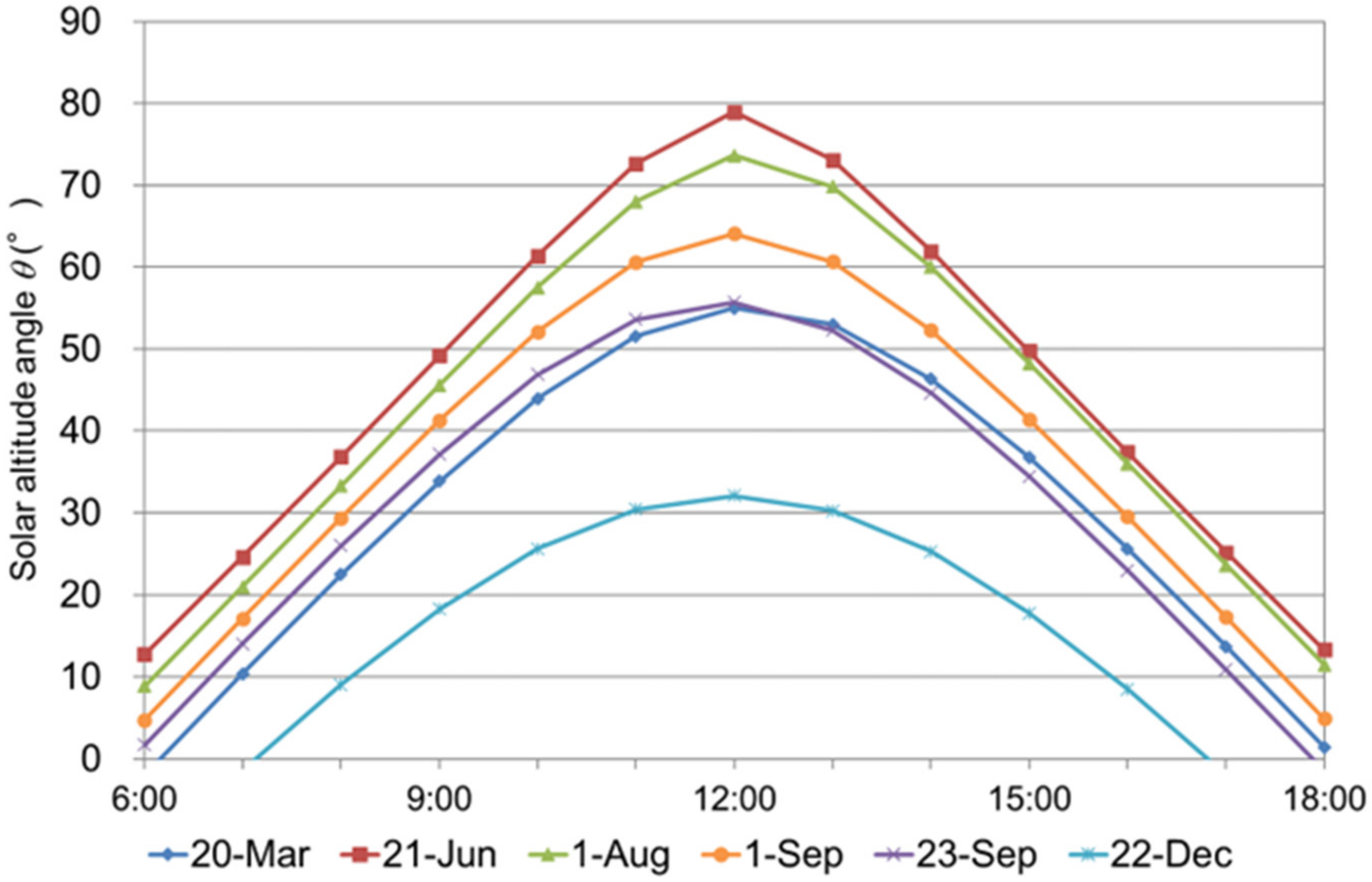
3.1. Different Solar Altitude Angles and Film Properties

3.1.1. Effect of Film Properties on Different Solar Altitude Angles

The reflectance, transmittance, and absorptance at each altitude angle are shown in Figure 7. The plots show the measurement results and the plot lines show the calculation results. The different shapes indicate the upward/downward reflected solar radiation, transmitted solar radiation, and absorbed solar radiation. The standard deviations of the measurement results are not overlaid on the figure because they are difficult to decipher, but the maximum and minimum standard deviations were as follows: 0.002–0.013 for upward reflection, 0.001–0.019 for downward reflection, and 0.009–0.083 for transmitted solar radiation. The values of the clear + upward reflective film and clear + film used in the calculations refer to the measurement results of JIS A 1494 by Harima et al. [18,19]. The value of clear refers to the AGC Inc. technical report [24]. The values used in the simulations are presented in Table 2. The measurement points at the time of day (near noon), when the angle between the vertical line of the window and the sun is greater than 60°, are plotted in Figure 7. In other words, these are oblique incidence measurements. In particular, in this case, the measurement error of the amount of solar radiation incident on the solar radiation meter installed parallel to the window surface becomes large, resulting in a deviation from the values measured by the spectrophotometer according to JIS. This suggests that when upward reflective films are introduced on the east and west surfaces, the specular reflection characteristics are strongly expressed during hours close to noon, when the sun enters the building from an oblique direction, and the reflected solar radiation may adversely affect the surrounding space.
During the daytime, from the summer solstice to August, when the sun’s altitude exceeds 60°, much of the incident solar radiation is reflected downward [18,19]. For all types of glass, the transmittance decreased, and the reflectance increased from around 60° solar altitude angle. The temporal variation in the solar altitude angle in Kobe is shown in Figure 8. As shown in Figure 7 and Figure 8, owing to the high solar altitude angle during the summer day, a large percentage of the incident solar radiation may be reflected by each glass surface. The temporal variation in the incident direct solar radiation on the vertical façade is shown in Figure 9. Because the amount of solar radiation incident on window surfaces during summer days is relatively small, the effect of increased reflectance is not expected to be significant. In terms of the amount of solar radiation incident on the facades, priority is given to measures between 8:00 and 10:00 for the east-facing facades and between 14:00 and 16:00 for the west-facing facades.

3.1.2. Effect of Different Films on the Thermal Environment

From Figure 7, when the altitude angle is 60° or less, most of the incident solar radiation (approximately 85%) is transmitted through the clear, but with clear + upward reflective film or clear + film, it is suppressed to approximately 50%, reducing the cooling requirement. The clear + upward reflective film has a relatively large absorptance of approximately 40%, which may cause the glass surface temperature to increase. For reference, the criteria for retroreflective (upward reflective) films in the Osaka High Tech certification system are an upward reflectance of 10% or more and a downward reflectance of 10% or less at an altitude angle of 60°, assuming a south face in summer [20].

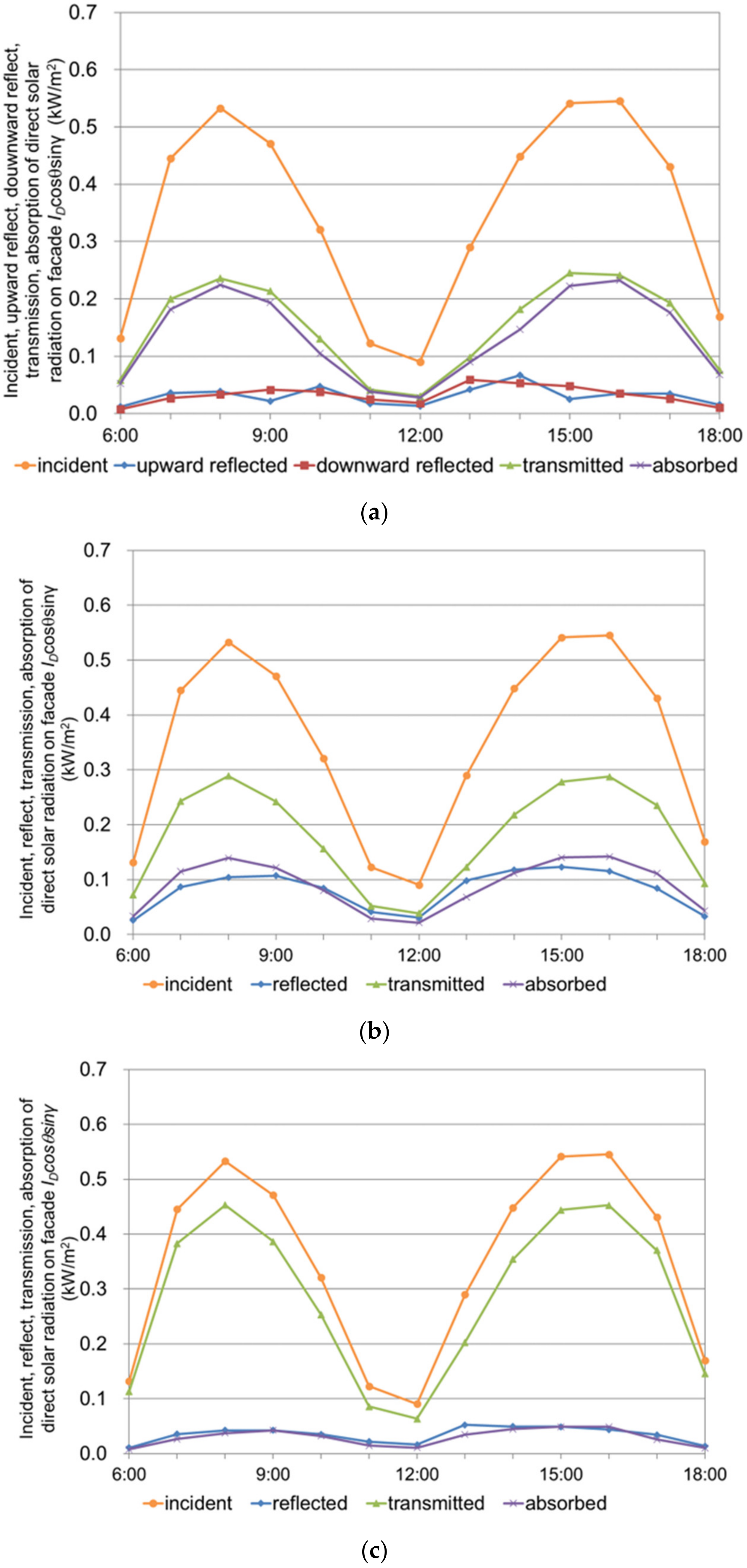
3.2. Solar Radiation Balance of Windows

Calculations based on previous studies [18,19] of upward reflection, downward reflection, transmission, and absorption of direct solar radiation on clear + upward reflective film windows, clear + film windows, and clear windows on 1 August and 1 September are shown in Figure 10 and Figure 11.

3.2.1. Difference in Solar Altitude Angle

The incident solar radiation was high from 8:00 to 10:00 for east-facing windows and from 14:00 to 16:00 for west-facing windows, and the amount of solar radiation reflected, transmitted, or absorbed depended on the solar altitude angle at that time. For the clear + upward reflective film, the fractions of absorbed and transmitted solar radiation are approximately equal (with the latter being slightly higher during the measurement times and around midday), and the ratio of upward and downward reflected solar radiation is lower than that of absorbed and transmitted solar radiation at all times.

3.2.2. Difference in Film Characteristics

The percentages of total solar radiation of reflected, transmitted, and absorbed solar radiation at 15:00 on September 1 for each window type are as follows: clear + upward reflective film window, 13%, 44%, 43%; clear + film window, 21%, 53%, and 26%; and clear window, 8%, 83%, and 9%, respectively. The upward reflective film is characterized by a large amount of absorbed solar radiation (43% versus 26% and 9% for clear + film and clear, respectively), the film is characterized by a large amount of reflected solar radiation (21% versus 13% and 8% for clear + upward reflective film and clear, respectively), and single pane glass is characterized by a large amount of transmitted solar radiation (83% versus 44% and 13% for clear + upward reflective film and clear + film, respectively).

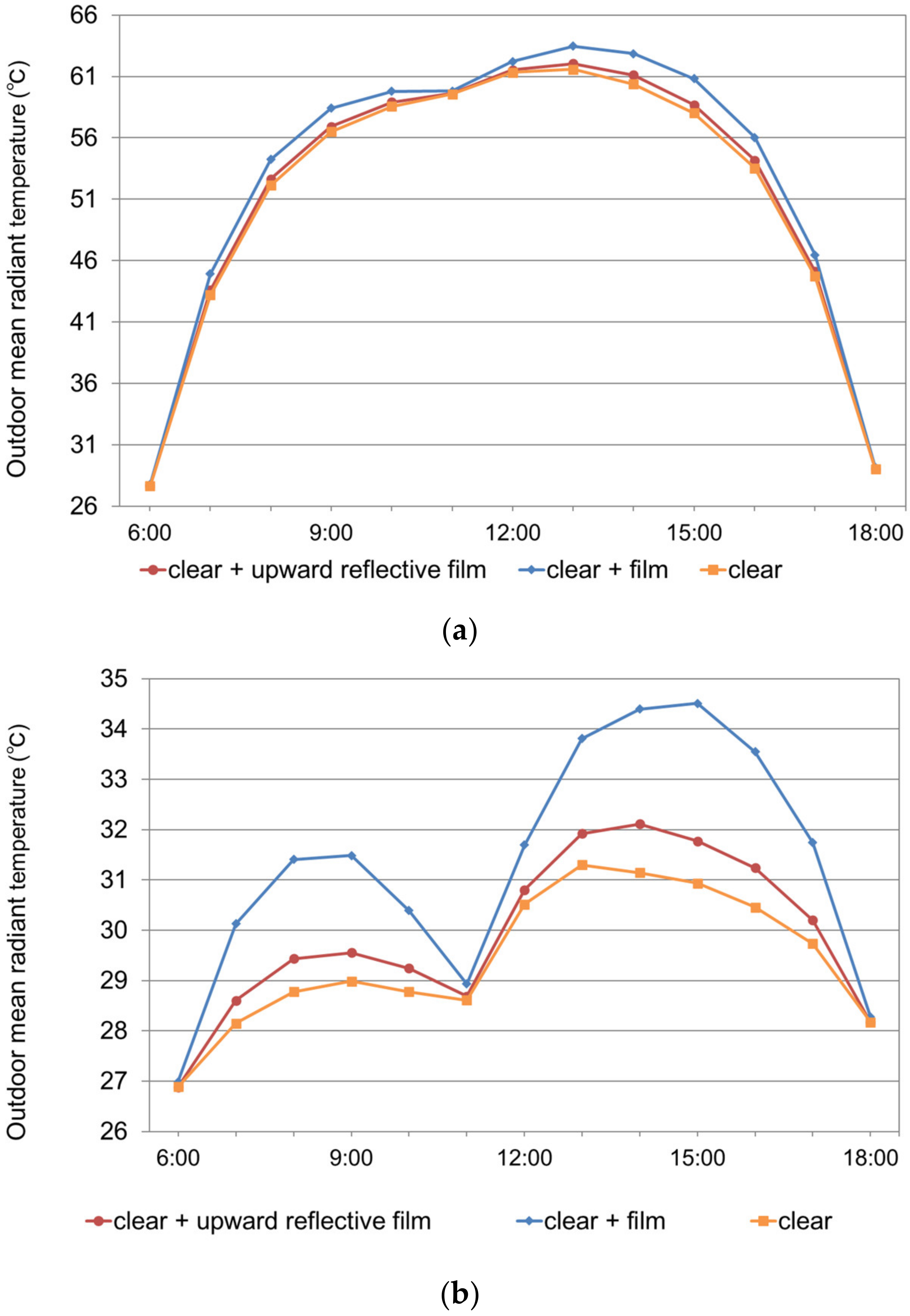
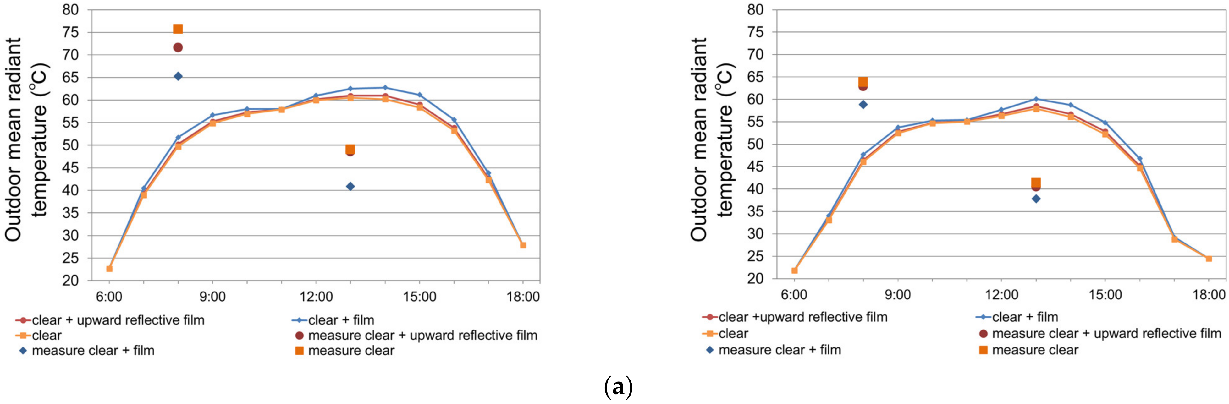
3.3. Glass Surface Temperature, Outdoor and Indoor Mean Radiant Temperature

3.3.1. Surface Temperature of Each Window

The calculated surface temperature for each window on 1 September is shown in Figure 12. The surface temperature depended on the absorptance of each window. The absorptances of clear + upward reflective, clear + film, and clear at 15:00 are 43%, 26%, and 9%, respectively. The calculated and measured surface temperatures in each window on September 10 and October 6 are shown in Figure 13. The measured surface temperatures tended to be higher than the calculated tmeperatures. The amount of solar radiation absorbed may vary depending on how the sensor is mounted. Qualitative relationships are generally consistent.

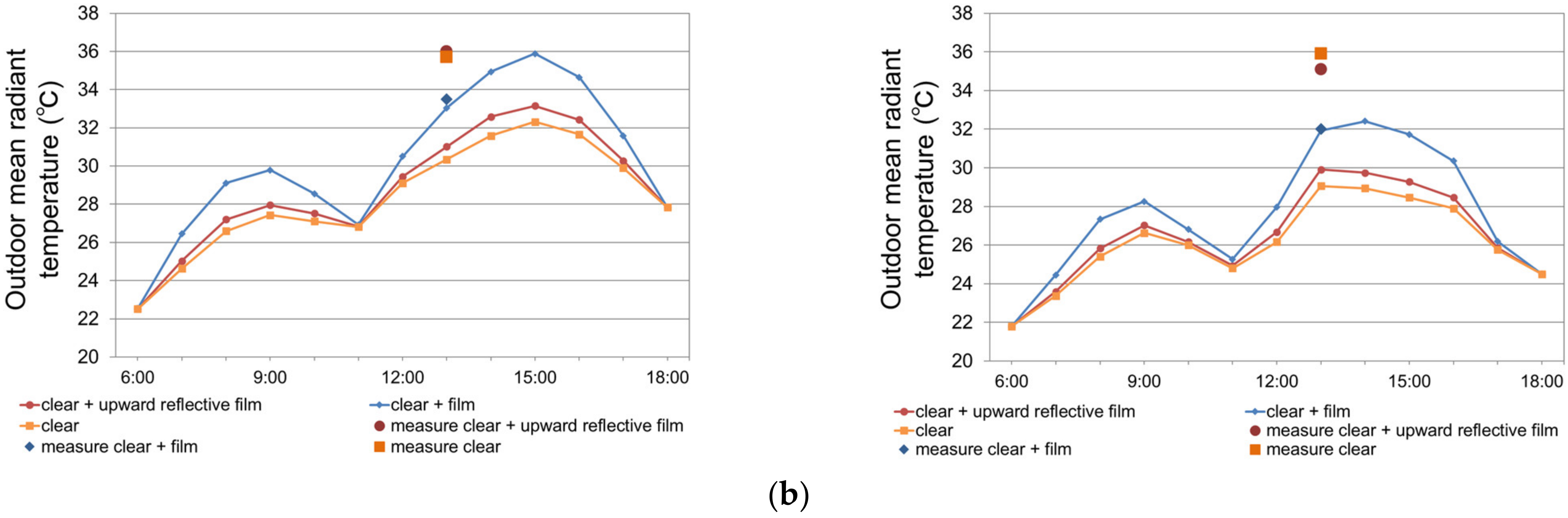
3.3.2. Outdoor Mean Radiant Temperature

The calculated outdoor mean radiant temperature for each window on 1 September is shown in Figure 14. The human body is exposed to direct solar radiation; therefore, MRT is very high. Outdoors, the effect of direct solar radiation from the lateral direction was dominant, and the MRT was not significantly affected by the difference in the films. MRT is also shown when no direct solar radiation is incident on the human body owing to the parasol. In this case, the MRT depends on the downward reflectance of each window. The downward reflectances of clear + upward reflective, clear + film, and clear at 15:00 were 13%, 21%, and 8%, respectively. The MRT corresponds to the reflectance, and the upward reflective film, which suppresses downward reflected solar radiation, has the same MRT as the single-pane glass, which transmits much of the solar radiation. The calculated and measured outdoor mean radiant temperatures on each window on September 10 and October 6 are shown in Figure 15. The maximum and minimum standard deviations of the measured values, which are not overlaid in the figure due to their complexity, are as follows: the standard deviations of the outdoor MRT on September 10 ranged from 12.2 °C to 15.3° in the morning and from 1.9 °C to 4.6 °C in the afternoon. The standard deviation of outdoor MRT on 6 October ranged from 2.0 °C to 4.8 °C in the morning and from 1.1 °C to 8.7 °C in the afternoon. The standard deviations of the readings in the absence of direct sunlight were all less than 1 °C. In the morning, the influence of a brief changeover between sunny and cloudy conditions caused a large variation in the measurement results, which did not agree with the calculated results. In the afternoon, there are shadows created by surrounding buildings and trees, so the calculated MRT values, which do not consider solar radiation, are not consistent with the measured values. There is no clear qualitative relationship between the observed and calculated values. The measured MRT values in outdoor spaces were calculated using the measured globe temperature, wind speed (measured near the globe sphere), and air temperature, which were affected by local shading and variable wind conditions. In the evaluation by calculation, some results do not match the measurement and calculation because we introduced an assumption to eliminate noise from sources other than the glass surface.

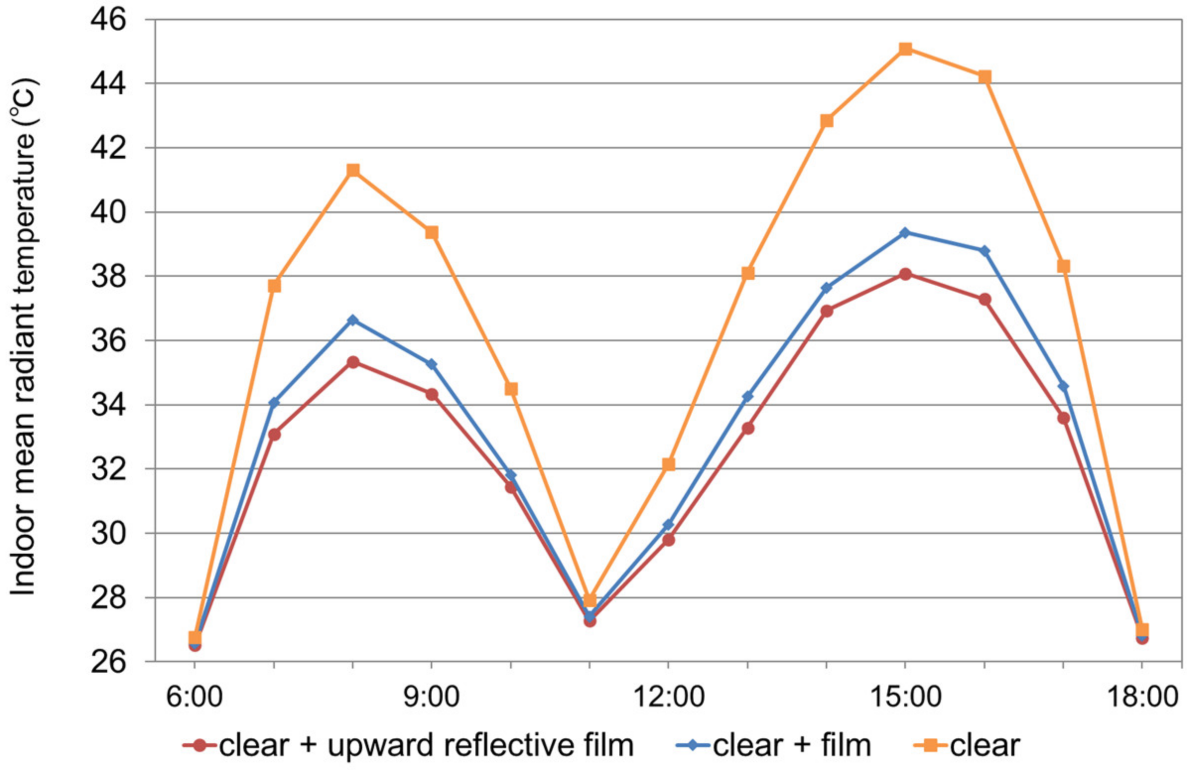
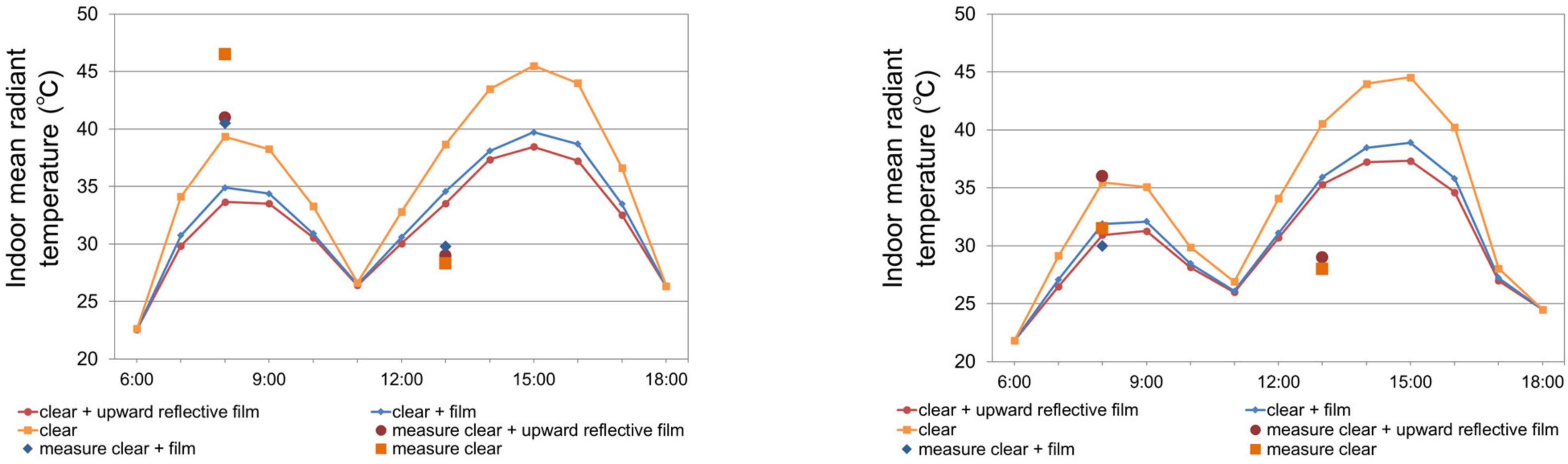
3.3.3. Indoor Mean Radiant Temperature

The calculated indoor mean radiant temperature for each window on 1 September is shown in Figure 16. The indoor mean radiant temperature depends on the transmittance of each window. The transmittances of the clear + upward reflective, clear + film, and clear at 15:00 were 44%, 53%, and 83%, respectively. Upward reflective and thermal barrier films contribute to the improvement of the indoor environment because they have lower transmittance than transparent glass. The calculated and measured indoor mean radiant temperatures on each window on 10 September and 6 October are shown in Figure 17. The measured indoor mean radiant temperature under direct solar radiation should be higher than that of the others; however, it is not higher at any time. Because the shape factor between the globe sphere and each target window was small, the measured MRT calculated from the globe temperature, wind velocity, and air temperature was affected by other objects in the room.

4. Discussion

The upward reflective film was developed not only to improve the indoor thermal environment, but also to mitigate the deterioration of the outdoor thermal environment by reducing the downward reflectance. As it is attached to the inside of the glass, it cannot suppress the solar radiation reflected from the outside of the glass. As a result, the downward solar reflectance of a clear + upward reflective film window was slightly greater than that of a clear window. The amount of incident solar radiation on the vertical facade was greater at 8:00, 9:00, 15:00, and 16:00 at the latitude of Kobe. The temporal variation of the incident direct solar radiation on the vertical façade at various latitudes on August 1 is shown in Figure 18. At other latitudes, the amount of solar radiation incident on the vertical facade was larger at the same time as in Kobe. Therefore, it is important to take measures in the morning on the east side and afternoon on the west side. The solar altitude angle during these hours did not exceed 60°. Therefore, for relatively frontal incidence, the reflection and transmission characteristics of the window with the film are important. At these incidence angles, the reflectance of the upward reflective film, which is characterized by upward reflection, is not very large. According to the calculation results, due to the low transmittance, the indoor MRT of a clear + upward reflective film window or a clear + film window was lower than that of a clear window. This was not in agreement with the measurement results in Figure 17. This may be because in the measurement results, influences from sources other than the glass surface were present; in the calculation, assumptions were introduced to eliminate them. In addition, it is difficult to perform measurements that consider both altitude and azimuth angles in an operational building. Outdoor MRT is affected by downward reflection, infrared radiation, and direct solar radiation to the human body (globe sphere), of which direct solar radiation has the greatest impact. The global temperature is the result of the integration of these factors; however, the effects of each factor can be considered by simulation. The outdoor MRT was suppressed to the same level as that of the clear window (from Figure 14) because the downward reflectance of the clear + upward reflective film window and the clear window was comparable (Figure 11). The sum of the transmission, convection, and radiation fluxes into the room on each window on 1 September, as calculated, is shown in Figure 19 (Supplementary figures for discussion). With clear + upward reflective film windows, a higher absorptance results in higher window surface temperatures and slightly higher convective and radiative heat fluxes; however, the lower transmittance results in less transmitted solar radiation and less total heat flux into the room. As a result, a clear + upward reflective film window improves the indoor environment without worsening the outdoor environment compared with the thermal barrier film. We also ran simulations for the winter solstice. As a result, we found that the solar gain effect could be enhanced by increasing the transmittance of the windows facing south, because the incident solar radiation to the south is large in winter.

5. Conclusions

In this study, the effects of upward reflective films applied to window glass on the thermal environment inside and outside the east- and west-facing windows were investigated based on the measurement results at actual building windows, considering the reflection and transmission characteristics depending on the angle of incident solar radiation. The upward reflective film used in this study retroreflects according to the vertical incidence angle corresponding to the solar altitude angle, but does not retroreflect in the horizontal solar orientation; therefore, it reflects upward but is not completely retroreflective to the sun. From the point of view of controlling the amount of solar radiation on the window façades of buildings, the reflected radiation does not need to return to the sun; it is sufficient to return to the sky, so this two-dimensional retroreflection is sufficient. Therefore, in this study, we did not consider solar orientation, but only the solar altitude angle. The amount of incident solar radiation on the vertical facade was greater around 8:00 and 9:00 and around 15:00 and 16:00. Therefore, it is important to take measures in the morning on the east side, and in the afternoon on the west side. The solar altitude angle at these times does not exceed 60°. Therefore, for relatively frontal incidence, the reflection and transmission characteristics of the window with the film are important.
The indoor MRT of upward reflective films applied to windows is lower than that of transparent windows because of their lower transmittances. The outdoor MRT of the upward reflective film on the window was suppressed to the same level as that of the transparent window because the downward reflectance was not significantly different from that of a transparent window. With upward reflective films applied to windows, the convective and radiative heat fluxes into the room are slightly larger owing to the high solar radiation absorptance; however, the transmitted heat flux into the room is reduced owing to the low solar radiation transmittance, resulting in a reduction in the total heat flux into the room. As a result, upward reflective films applied to windows improve the indoor environment without degrading (or even improving) the outdoor environment. In addition, when upward reflective films are introduced to the east and west surfaces, the specular reflection characteristic is strongly expressed during hours close to noon when the sun is incident from an oblique direction, and there is concern about the adverse effects of reflected solar radiation on the surrounding space.

Author Contributions

Conceptualization, S.K. and H.T.; methodology, S.K.; software, S.K.; validation, S.K. and H.T.; formal analysis, S.K.; investigation, S.K.; resources, S.K.; data curation, S.K.; writing—original draft preparation, S.K.; writing—review and editing, H.T.; visualization, S.K.; supervision, H.T.; project administration, H.T.; funding acquisition, H.T. All authors have read and agreed to the published version of the manuscript.

Funding

This study was funded by Kobe as “Research project on measures against extreme temperatures in outdoor public spaces in Kobe City”, and “Research project on measures against extreme temperatures in public buildings in Kobe City”.

Institutional Review Board Statement

Not applicable.

Informed Consent Statement

Not applicable.

Data Availability Statement

Not applicable.

Acknowledgments

Field measurements were conducted with the cooperation of the city of Kobe. Measurement data of reflectance and transmittance for each vertical incidence angle of window films were provided by T. Harima, of Dexerials Corporation.

Conflicts of Interest

The authors declare no conflict of interest. The funders had no role in the design of the study; in the collection, analyses, or interpretation of data; in the writing of the manuscript; or in the decision to publish the results.

References

  1. Hyunjung, L.; Helmut, M. Thermal comfort of pedestrians in an urban street canyon is affected by increasing albedo of building walls. Int. J. Biometeorol. 2018, 62, 1199–1209. [Google Scholar] [CrossRef]
  2. Takebayashi, H. High-reflectance technology on building façades: Installation guidelines for pedestrian comfort. Sustainability 2016, 8, 785. [Google Scholar] [CrossRef] [Green Version]
  3. Yuan, J.; Emura, K.; Farnham, C. A method to measure retro-reflectance and durability of retro-reflective materials for building outer walls. J. Build. Phys. 2014, 38, 500–516. [Google Scholar] [CrossRef]
  4. Yuan, J.; Farnham, C.; Emura, K. Development of a retro-reflective material as building coating and evaluation on albedo of urban canyons and building heat loads. Energy Build. 2015, 103, 107–117. [Google Scholar] [CrossRef]
  5. Yuan, J.; Emura, K.; Sakai, H.; Farnham, C.; Lu, S. Optical analysis of glass bead retro-reflective materials for urban heat island mitigation. Sol. Energy 2016, 132, 203–213. [Google Scholar] [CrossRef]
  6. Yuan, J.; Emura, K.; Farnham, C.; Sakai, H. Application of glass beads as retro-reflective façades for urban heat island mitigation: Experimental investigation and simulation analysis. Build. Environ. 2016, 105, 140–152. [Google Scholar] [CrossRef]
  7. Rossi, F.; Pisello, A.; Nicolini, A.; Filipponi, M.; Palombo, M. Analysis of retro-reflective surfaces for urban heat island mitigation: A new analytical model. Appl. Energy 2014, 114, 621–631. [Google Scholar] [CrossRef]
  8. Rossi, F.; Castellani, B.; Presciutti, A.; Morini, E.; Filipponi, M.; Nicolini, A.; Santamouris, M. Retroreflective façades for urban heat island mitigation: Experimental investigation and energy evaluations. Appl. Energy 2015, 145, 8–20. [Google Scholar] [CrossRef]
  9. Rossi, F.; Castellani, B.; Presciutti, A.; Morini, E.; Anderini, E.; Filipponi, M.; Nicolini, A. Experimental evaluation of urban heat island mitigation potential of retro-reflective pavement in urban canyons. Energy Build. 2016, 126, 340–352. [Google Scholar] [CrossRef]
  10. Castellani, B.; Morini, E.; Anderini, E.; Filipponi, M.; Rossi, F. Development and characterization of retro-reflective colored tiles for advanced building skins. Energy Build. 2017, 154, 513–522. [Google Scholar] [CrossRef]
  11. Ichinose, M.; Ishino, H.; Kohri, K.; Nagata, A. Calculation Method of Radiant Heat Transfer with Directional Characteristics. In Proceedings of the Technical Papers of Annual Meeting of IBPSA–Japan, Tokyo, Japan, 10–12 January 2005. [Google Scholar]
  12. Ichinose, M.; Inoue, T.; Nagahama, T. Effect of retro-reflecting transparent window on anthropogenic urban heat balance. Energy Build. 2017, 157, 157–165. [Google Scholar] [CrossRef]
  13. Nakaohkubo, K.; Hoyano, A.; Asawa, T.; Fukasawa, H. Development of outdoor heat balance simulation considering directional characteristics of reflected solar radiation from the building external surfaces. J. Environ. Eng. AIJ 2008, 625, 275–282. [Google Scholar] [CrossRef] [Green Version]
  14. Nishioka, M.; Inoue, S.; Sakai, K.; Nakao, M.; Nabeshima, M. Numerical simulation on basic properties of retroreflectors, Performance evaluation of solar retroreflectors. J. Environ. Eng. AIJ 2008, 630, 1013–1019. [Google Scholar] [CrossRef] [Green Version]
  15. Nishioka, M.; Inoue, S.; Sakai, K. Retroreflective properties calculating method based on geometrical-optics analysis, Performance evaluation of solar retroreflectors. J. Environ. Eng. AIJ 2008, 633, 1249–1254. [Google Scholar] [CrossRef]
  16. Yoshida, S.; Yumino, S.; Uchida, T.; Mochida, A. Effect of windows with heat ray retroreflective film on outdoor thermal environment and building cooling load. J. Heat Isl. Inst. Int. 2015, 9, 67–72. [Google Scholar]
  17. JIS A 1494-2021; Measurement Methods for Performance of Solar Radiation Retro-Reflectivity on Adhesive Films for Glazings. JISC: Bristol, UK, 2021.
  18. Harima, T.; Nagahama, T. Evaluation methods for retroreflectors and quantitative analysis of near-infrared upward reflective solar control window film—Part I: Theory and evaluation methods. Sol. Energy 2017, 148, 177–192. [Google Scholar] [CrossRef]
  19. Harima, T.; Nagahama, T. Evaluation methods for retroreflectors and quantitative analysis of near-infrared upward reflective solar control window film—Part II: Optical properties evaluation and verification results. Sol. Energy 2017, 148, 164–176. [Google Scholar] [CrossRef]
  20. The Osaka Heat Island Countermeasure Technology Consortium. Overview of the Certification System. Available online: http://www.osakahitec.com/cert/gaiyo2.pdf (accessed on 25 October 2021).
  21. Fox, J.; Osmond, P.; Peters, A. The Effect of Building Facades on Outdoor Microclimate—Reflectance Recovery from Terrestrial Multispectral Images Using a Robust Empirical Line Method. Climate 2018, 6, 56. [Google Scholar] [CrossRef] [Green Version]
  22. Levinson, R.; Chen, S.; Slack, J.; Goudey, H.; Harima, T.; Berdahl, P. Design, characterization, and fabrication of solar-retroreflective cool-wall materials. Sol. Energy Mater. Sol. Cells 2020, 206, 110117. [Google Scholar] [CrossRef] [Green Version]
  23. Yuan, J.; Emura, K.; Farnham, C. Evaluation of retro-reflective properties and upward to downward reflection ratio of glass bead retro-reflective material using a numerical model. Urban Clim. 2021, 36, 100774. [Google Scholar] [CrossRef]
  24. AGC Inc. Flat Glass Building Materials General Catalog, Technical Data Edition. Available online: https://asahiglassplaza.icata.net/iportal/CatalogDetail.do?method=initial_screen&volumeID=AGC00001&categoryID=100030000&catalogID=394950000&type=mc&position=2&sortKey=CatalogMain11590000&sortOrder=DESC&designID=AGCD001 (accessed on 25 October 2021).
Figure 1. Relationship between solar incidence angle and solar elevation angle in elevation (sloped and vertical facades).
Sustainability 15 03848 g001
Figure 2. Concept of solar radiation components measured in this study. The vertical incident solar radiation is ID · cosθsinγ.
Sustainability 15 03848 g002
Figure 3. Schematic showing retroreflective (upward reflective) film affixed to the back of a float glass window, showing transmitted visible light and upward reflected near-infrared light.
Sustainability 15 03848 g003
Figure 4. The size of the window and the application of the film (from indoors).
Sustainability 15 03848 g004
Figure 5. Target building and surroundings; the east window is located on the second floor, and the west window on the first floor.
Sustainability 15 03848 g005
Figure 6. The upper figure shows the arrangement of the measuring instruments. On the left is a cross-sectional view, and on the right is a plan view. The bottom row shows the photos taken during the measurements; the left shows the solar radiation and the right shows the global temperature measurement.
Sustainability 15 03848 g006
Figure 7. The reflectance, transmittance, and absorptance for each vertical incidence angle (= solar altitude angle). (a) clear + upward reflective film, (b) clear + film, and (c) clear.
Sustainability 15 03848 g007aSustainability 15 03848 g007b
Figure 8. The temporal variation of solar altitude angle in Kobe city.
Sustainability 15 03848 g008
Figure 9. The temporal variation of direct solar radiation incident on the vertical facade.
Sustainability 15 03848 g009
Figure 10. Calculations based on previous studies [18,19] of upward reflection, downward reflection, transmission, and absorption of direct solar radiation on 1 August. (a) clear + upward reflective film window, (b) clear + film window, and (c) clear window.
Sustainability 15 03848 g010
Figure 11. Calculations based on previous studies [18,19] of upward reflection, downward reflection, transmission, and absorption of direct solar radiation on 1 September. (a) clear + upward reflective film window, (b) clear + film window, and (c) clear window.
Sustainability 15 03848 g011
Figure 12. Calculated surface temperature on each window on 1 September.
Sustainability 15 03848 g012
Figure 13. Calculated and measured surface temperature on each window on 10 September and 6 October.
Sustainability 15 03848 g013
Figure 14. Calculated outdoor mean radiant temperature on each window on 1 September. (a) solar radiation incident on the human body, and (b) solar radiation not incident on the human body.
Sustainability 15 03848 g014
Figure 15. Calculated and measured outdoor mean radiant temperature on each window on 10 September and 6 October. ((a). with solar radiation incident on the human body, (b). without solar radiation incident on the human body).
Sustainability 15 03848 g015aSustainability 15 03848 g015b
Figure 16. Calculated indoor mean radiant temperature on each window on 1 September.
Sustainability 15 03848 g016
Figure 17. Calculated and measured indoor mean radiant temperature on each window on 10 September and 6 October.
Sustainability 15 03848 g017
Figure 18. The temporal variation of incident direct solar radiation on the vertical façade at various latitudes on 1 August.
Sustainability 15 03848 g018
Figure 19. Sum of transmission, convection, and radiation fluxes into the room on each window on 1 September.
Sustainability 15 03848 g019
Table 1. The specifications and measurement methods of each instrument.
Measurement ItemMeasuring EquipmentMeasurement Method
Atmospheric temperatureESPEC Corporation
Thermo Recorder RS–14
thermistor
Intervals: 1 min
Accuracy: Average ± 0.5 °C (0–55 °C)
HumidityESPEC Corporation
Thermo Recorder RS–14
Polymer film resistance type
Intervals: 1 min
Accuracy: ±5%RH
(25 °C 50%RH)
Globe temperatureEIKO INSTRUMENTS
Globe sphere Diameter 15 cm
ESPEC Corporation
Thermo Recorder RT–32S
thermistor
Intervals: 1 min (8:00 to 17:00)
Accuracy: Average ± 0.3 °C
(−20 to 80 °C)
Surface temperatureThermo Recorder RT–32S
thermistor
Accuracy: Average ± 0.3 °C
(−20 to 80 °C)
Intensity of solar radiationTsuruga Electric Corporation
LP PYRA03
Intervals: 5 s (8:00 to 17:00)
Range: 0–2000 W/m2
Wind
velocity
KANOMAX
Anemo master MODEL6034
Average of 30 instantaneous values
Accuracy:±(3% of the indicated value + 0.1) m/s
Wind
direction
Self-made streamersThe most frequent direction during the measurement of wind speed.
Thermal imageFLIR Systems
FLIR ONE
Photograph the window to be measured (for checking surface temperature)
Table 2. Values for clear + film and clear + retroreflective (upward reflective) measured in accordance with JIS A 1494 by Harima et al., and a clear value according to the AGC’s technical report.
Vertical
Incidence
(Solar Altitude) Angle [°]
Retroreflective Film
(Upward Reflective Film)
FilmClear
ρupρdownταρupρdownταρupρdownτα
00.130.030.460.390.000.190.550.260.000.080.860.06
100.090.060.450.400.000.190.550.260.000.080.860.06
200.080.060.450.410.000.200.550.260.000.080.860.06
300.070.060.440.420.000.200.540.260.000.080.850.07
400.070.070.440.430.000.210.530.260.000.080.830.09
500.050.090.450.410.000.230.510.260.000.090.820.09
600.150.120.410.330.000.260.490.250.000.110.790.10
700.150.210.340.310.000.340.430.240.000.180.700.12
800.110.410.210.270.000.610.240.150.000.300.530.17
900.001.000.000.000.001.000.000.000.001.000.000.00
Disclaimer/Publisher’s Note: The statements, opinions and data contained in all publications are solely those of the individual author(s) and contributor(s) and not of MDPI and/or the editor(s). MDPI and/or the editor(s) disclaim responsibility for any injury to people or property resulting from any ideas, methods, instructions or products referred to in the content.

