Article

Experimental Research on a Solar Energy Phase Change Heat Storage Heating System Applied in the Rural Area

1
School of Environment Science and Engineering, Tianjin University, 92 Weijin Road, Tianjin 300072, China
2
Tianjin Key Laboratory of Built Environment and Energy Application, Tianjin University, Tianjin 300072, China
*
Author to whom correspondence should be addressed.
Sustainability 2023, 15(3), 2575; https://doi.org/10.3390/su15032575
Submission received: 29 November 2022 / Revised: 21 January 2023 / Accepted: 29 January 2023 / Published: 31 January 2023

Abstract

:
Thermal energy storage technology can effectively promote the clean heating policy in northern China. Therefore, phase-change heat storage heating technology has been widely studied, both theoretically and experimentally, but there is still a lack of engineering application research. According to the characteristics of heating load in northern rural areas, a kind of solar heating system using phase-change materials (PCMs) for heat storage is proposed. Furthermore, a farmhouse is used to demonstrate the practical engineering applications of the heating system. The heating system consists of the phase-change heat storage device (PCHSD), solar thermal panels, and a floor radiant heating terminal, which can realize the effective utilization of solar energy. Considering solar power generation capacity, heating load characteristics of farm buildings, and the local electricity price model, four potential operation modes of the heating system are established. Then, the corresponding control strategies are proposed for the four operating modes. The actual operation data of the heating system under different operating modes were collected continuously, and the application effect of the heating system was evaluated from the aspects of thermal efficiency of the device, the renewable energy efficiency, thermal comfort level, and economy. The experimental results show that: (1) The thermal efficiency of the device is mainly affected by the heating load, which can reach more than 80% during the test period; (2) the renewable energy efficiency of the system is positively correlated with the solar radiation intensity, and the maximum can reach 100% when the solar radiation is sufficient; (3) the system maintains excellent thermal comfort in all conditions, with the average and the highest thermal comfort time accounting for 80% and 100%, respectively; (4) compared with the average level of existing clean heating technology, the annual operating cost of the system is reduced by 27.3%, and the economy is significant. The results show that the system achieves effective performance during the test period.

1. Introduction

Currently, central heating demand in northern China is mainly met by burning fossil fuels, which causes serious environmental damage. To promote clean heating in northern China, China actively encourages the use of solar energy and other renewable energy sources for heating in light of local conditions [1]. Because of the time and spatial mismatch between renewable energy production and building energy demand, figuring out how to capture copious solar energy during the day for night use has become a pressing issue. One of the best ways to solve this problem is to use phase-change materials (PCMs) in thermal energy storage systems (TESs) [2]. Phase-change heat storage has received a lot of attention as a solution with a high heat storage density, consistent latent heat temperature, and ease of control [3].
In recent years, the improvements in thermal and physical properties of phase-change materials have been of widespread concern. In a solar phase-change heating system, organic materials represented by paraffin are widely used in the present application because of their stable performance and moderate price [4]. However, due to the poor thermal conductivity of organic phase-change materials, many studies use the addition of substances with high thermal conductivity to change the phase-change materials into composite phase-change materials to improve their thermal conductivity. Nidhal et al. [5] and Muhammad et al. [6] added nanoparticles to phase-change materials (PCMs) to enhance their thermal conductivity. The experimental and numerical simulation results show that, compared with ordinary PCMs, the composite phase-change material has great improvements in the charging and discharging stage, and saves a lot of time. Imran et al. added nano-enhanced phase-change material (NePCM) into the electronic cooling system. The experiment showed that the reference temperature of Cu foam integrated heat sink (CufmHS) decreased to a maximum of 36.95%, and the maximum working time increased by 288% [7] compared with that of no nanoparticles. Rabia et al. used a finite specific heat capacity method to numerically simulate the phase transition process of mPCM slurry. The experiment showed that with the increase in the mass concentration of mPCM, the local Nusselt number increased compared with pure water. The volume and surface temperatures were found to be 3.12 K and 1.2 K higher than those recorded in pure water [8].
The phase-change thermal storage system involved in the existing research can be divided into two types: active [9] and passive [10]. Gholamibozanjani et al. compared the thermal performance of passive and active PCM systems and discovered that over 10 winter test days, when storing the same amount of heat, test rooms using active thermal storage systems (ATSSs) consumed 22% less energy than test rooms using passive thermal storage systems (PTSSs) [11]. Nidhal et al. used numerical methods to evaluate the thermal performance of an integrated phase-change material building wall. Two organic phase-change materials, n-octadecane and n-eicosane, and an inorganic phase-change material, calcium chloride hexahydrate, were tested under high-temperature conditions. The results show that n-octadecane has the best effect when the temperature in the laboratory is close to 27 °C in the passive heat-storage mode of building walls [12]. Chen et al. created a PCM-based mixed active and passive ventilation wall and investigated it using experimental and numerical simulation approaches. The results reveal that the wall has a substantial influence on raising the temperature of the interlayer and the irradiated surface, that the wall’s heat storage capacity improves by 35.27–47.89%, and that the wall’s heat-release capacity increases by 49.93–60.21% [13]. Stathopoulos et al. charged Microtech 37D paraffin with electricity and tested it under artificial conditions in order to investigate the potential of an air–PCM heat exchanger to transfer energy loads. Their research shows that reasonable active thermal storage can shift energy loads from peak to off-peak hours while maintaining acceptable thermal comfort and indoor air quality conditions [14]. Xu et al. investigated the thermal performance and building energy efficiency of an active solar heating wall and phase-change material system in an experimental setting. The test findings reveal that the system saves 1.93 kW/h of energy and achieves an interior temperature of 21.9 °C, which is higher than the comparative room [15]. Lu et al. proposed a dual-tube PCM floor heating system with three independent heating modules. The results of a 26-day experiment show that the system can provide a comfortable indoor thermal environment, and the average indoor daily temperature fluctuation is 3 °C [16]. In summary, the active PCM system has a better energy-saving effect than the passive PCM system because heat can be stored and released according to load demand.
The existing research on active PCM heating generally involves the coupling effect of phase-change heat storage devices and solar thermal or electric heating. Zhou et al. experimentally studied the heat storage, heat release and heat insulation performance of PCM centralized solar hot water systems under different solar radiation levels by using electric heating instead of solar energy. The results show that the performance of the system is better than that of the conventional hot water system [17]. El Khadraoui et al. invented a solar air heater with PCM. The test results show that the daily energy efficiency and exergy efficiency of the solar accumulator reach 33.9% and 8.5%, respectively [18]. Xu et al. invented a dual-channel solar thermal storage wall system filled with eutectic phase-change materials. The heat flux analysis of the system shows that the heating efficiency can be improved by using dual channels [19]. The solar energy used in the above PCM system as the only heat source has strong instability in practical application scenarios and cannot ensure the continuous operation of the system. In order to make better use of the off-peak energy at night and realize the peak-cutting and valley filling, some studies have applied the strategy of night energy storage. Singh et al. invented a phase-change ceiling radiant cooling system and applied the system based on the TOU price control strategy. The research results showed that the operating cost was reduced by at least 17.5% and up to 22.4% [20]. To take advantage of low-cost electricity for heating at night (11 p.m. to 8 a.m.), Lin et al. developed an underground heating system with a shape-stable PCM plate. Specifically, the electric heater charges the PCM at night and then releases it into the indoor air during the day [21]. Cheng et al. developed a PCM with enhanced thermal conductivity and a stable shape for residential floor heating systems. The system uses cheap electricity to store heat at night and can meet heating needs throughout the day [22]. However, these studies mainly analyzed the performance of the PCM heating system based on the single operating mode of daytime or night energy storage, which cannot effectively characterize the ability of the system to cope with changes in meteorological conditions and tiered electricity price policies.
As an effective way to reduce operating energy consumption, the intermittent heating strategy has received extensive attention [23]. Li et al. utilized the heat storage and release processes of composite phase-change walls to optimize the control strategy for intermittent heating. The results show that the heat released by the composite phase-change wall can effectively maintain indoor thermal comfort and reduce the heating energy consumption by 4.74% [24]. Xu et al. established a physical model to simulate and predict the thermal behavior of buildings, and the simulation results showed that the energy-saving rate of a system using intermittent heating over a whole week can reach about 20% compared with continuous heating [25]. Wang et al. conducted a field test on a dwelling and showed that intermittent heating systems can provide a comfortable indoor thermal environment. However, due to the large thermal time constant of the thermal insulation of the envelope, the associated energy-saving rate is around 5% compared to the continuous heating system [26]. Although there are many studies on intermittent heating, there are fewer studies on the suitability of intermittent heating for PCM heating systems.
In this study, a phase-change heat storage solar heating system is proposed for a farmhouse, and four operating modes of the heating system are constructed based on the solar energy production capacity, heating load characteristics, and local electricity price model. Experimentation is used to gather continuous test data, and the appropriateness of intermittent heating for this system is evaluated. The system performance is explored from the aspects of renewable energy utilization efficiency, phase-change heat storage device performance, thermal comfort, and economy.

2. Materials and Methods

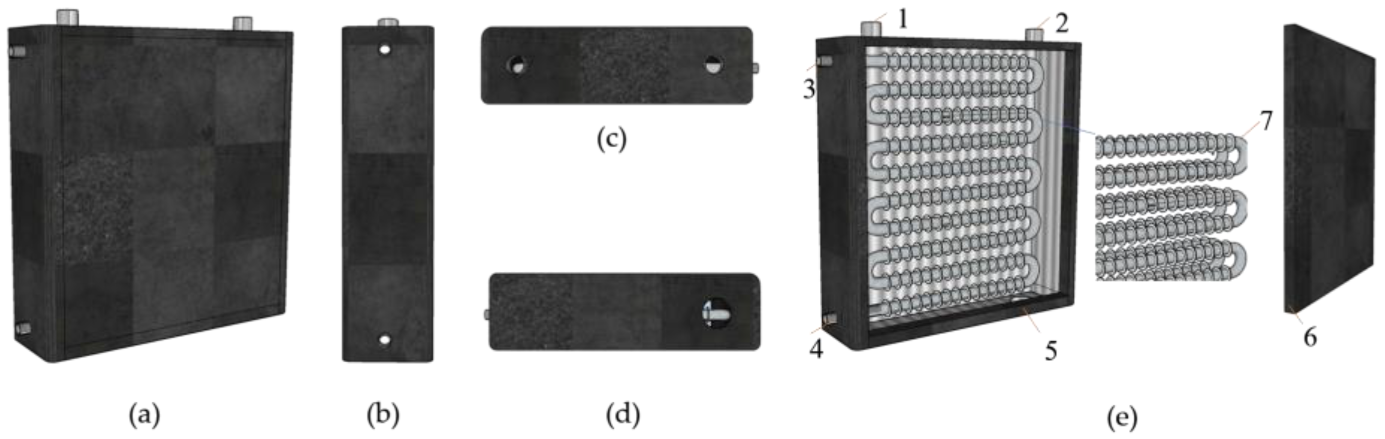
2.1. The Phase-Change Heat Storage Device

The phase-change heat storage device (PCHSD) used in this heating system was designed by laboratory team member in a previous research work, detailed in [27]. The structure of the phase-change heat storage device was designed by ANSYS simulation, and the optimal fin number, spacing and thickness of the device were finally determined. The device is made of stainless-steel welding, with a stainless-steel fin tube, water divider, and positioning member arranged inside. The external insulation of the equipment is rubber and plastic sponge board, which is made of organic thermal insulation material. Its thickness is 50 mm and its thermal conductivity is 0.035 W/(m·K). The size of the device is 740 mm × 160 mm × 930 mm, and two sets of coils are horizontally parallel internally (Figure 1). Each set of coils consists of 10 sections of 615 mm horizontal pipe and 9 sections of semicircular pipe with a radius of 45 mm. The inner diameter and wall thickness of the pipe are 16 mm and 2 mm, respectively. Fin thickness and length are 2 mm and 25 mm, respectively. Coils are evenly spaced, and the centerline spacings of the two adjacent pipes in the vertical and horizontal directions are 90 mm and 80 mm, respectively.
In winter, the outlet water temperature of the heat pipe solar collector in Tianjin is 55 °C–65 °C. According to JGJ142-2012 [28] the water supply temperature of a hot water floor radiant heating system in civil buildings should be between 35 °C and 45 °C. Given that the outlet water temperature of the solar collector used to melt the PCM in this experiment is greatly affected by weather, the temperature of the PCM chosen should be moderate and the latent heat value as large as possible. In this paper, TH-SL49 phase-change material produced by Hubei Saimo New Energy Technology Co., LTD is selected. The type of PCM is paraffin. The temperature of TH-SL49 is between 40 °C and 50 °C in this experiment, and the physical properties of the phase-change materials are investigated using differential scanning calorimetry (DSC). As shown in Figure 2 the peak melting temperatures (Tpm) and peak solidification temperatures (Tps) of PCM are 50.5 °C and 44.8 °C, respectively. The latent heat of melting and solidification are 238.2 and 236.9 kJ/kg, respectively. The thermophysical parameters of the materials used in PCHSD are shown in Table 1.
First of all, the device is designed to use only the heat provided by the solar collector as far as possible to meet the room heating requirements. Therefore, firstly, the indoor heat load is calculated as 800 W by using the information related to the room area and the enclosure structure. Then, the total heat of the solar collector is calculated as 9.66 kWh by using the solar collector area of Equations (1) and (2). As the latent heat value of the phase-change material selected in this experiment is 238.2 kJ /kg, it is calculated that at least 146 kg of phase-change material is required. In order to ensure sufficient heat storage in the device, the calculated value is multiplied by the coefficient 1.1, and the mass of the phase-change material added in this experiment is 163 kg.

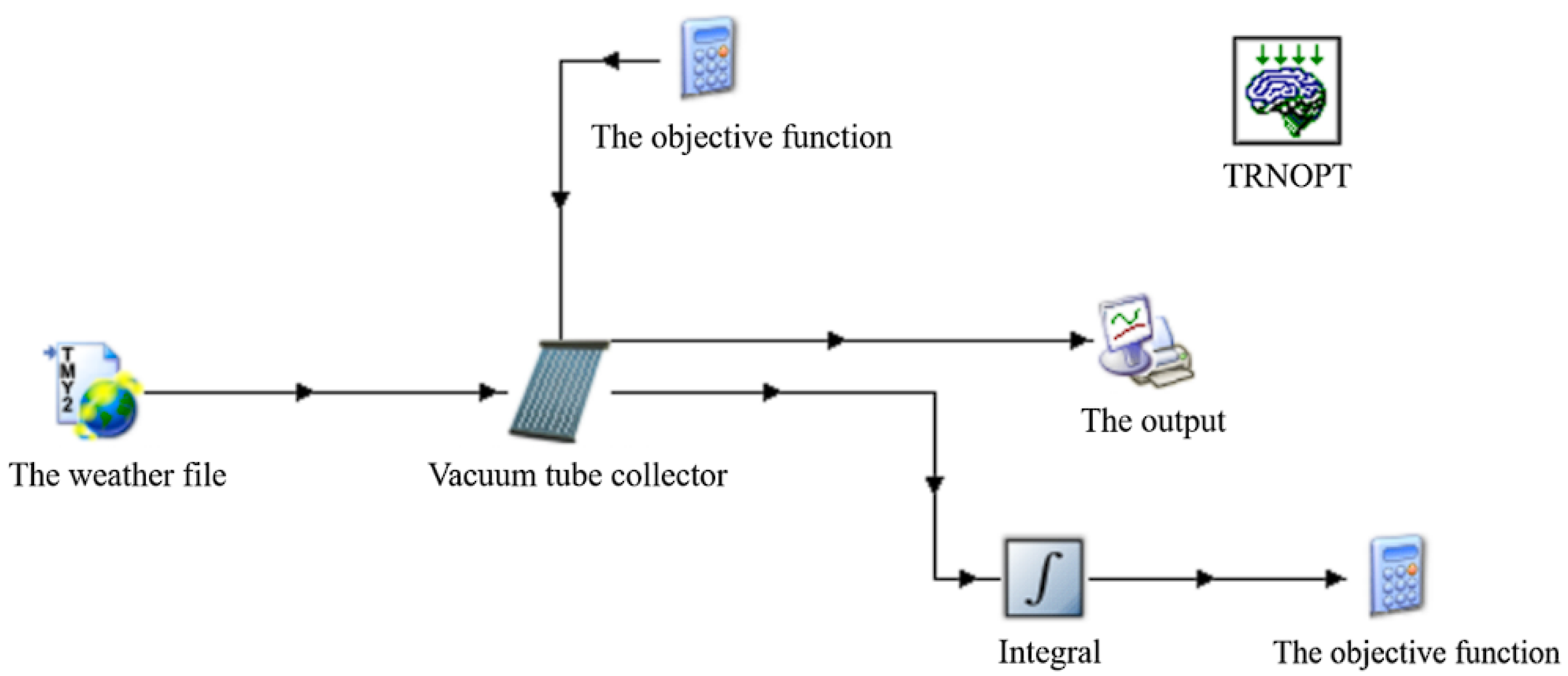
2.2. The Design Method of Solar Energy Collection System

This system is an indirect heating system. According to “Technical Standard for Solar Heating Engineering (GB 50495)”, the total area of the solar collector of the short-term indirect heat storage system can be calculated according to Equation (1) [29].
A I N = A C ( 1 + U L A C U h x A h x )
where AIN is the total area of the indirect system solar collector, m2; AC is the total area of the direct system solar collector, m2, which can be calculated according to Equation (2); Uhx is the heat-transfer coefficient of the heat exchanger, W/(m2·°C); Ahx is the heat-transfer area of the indirect system heat exchanger, m2.
A C = 86,400 Q J f J T η c d ( 1 η L )
where QJ is the design load for the solar heat-collection system, W; f is the solar guarantee rate, (%), and it is 50% in Tianjin; JT is the 12-month average daily solar irradiation on the lighting surface of the local collector, J/(m2·d), and it is 12.61 × 10⁶ in Tianjin; ηcd is the average heat collection efficiency of the collector based on the total area, %, and it is 35% in Tianjin; ηL is the heat loss rate of pipeline and heat storage device, %, and it is 20% in Tianjin.
The orientation and inclination angle of solar collector installation will directly affect the amount of solar radiation collected. The optimum installation azimuth and inclination angle of the collector varies with the season and region of application. It is mentioned in the “Technical Standard for Solar Heating Engineering” (GB 50495) that the solar collector should best be set in the direction of due south, or south by east/west 20°; the best installation inclination is to add 10° to the local latitude [29].
In this study, TRNOPT, an optimization tool of TRNSYS software, was used to optimize the azimuth and inclination angle of solar collectors. The optimization model is shown in Figure 3. The optimization objective is to maximize the thermal collection of solar collectors throughout the heating season. The optimization interval of the azimuth angle is –5° to 5°, the optimization interval of inclination angle is 35° to 50°, and the iteration step is 0.1. Hooke–Jeeves algorithm was used to solve the optimization function, and the optimal azimuth angle and inclination angle were 2.133° and 48.172°, respectively.

2.3. The Phase-Change Thermal Storage Solar Heating System

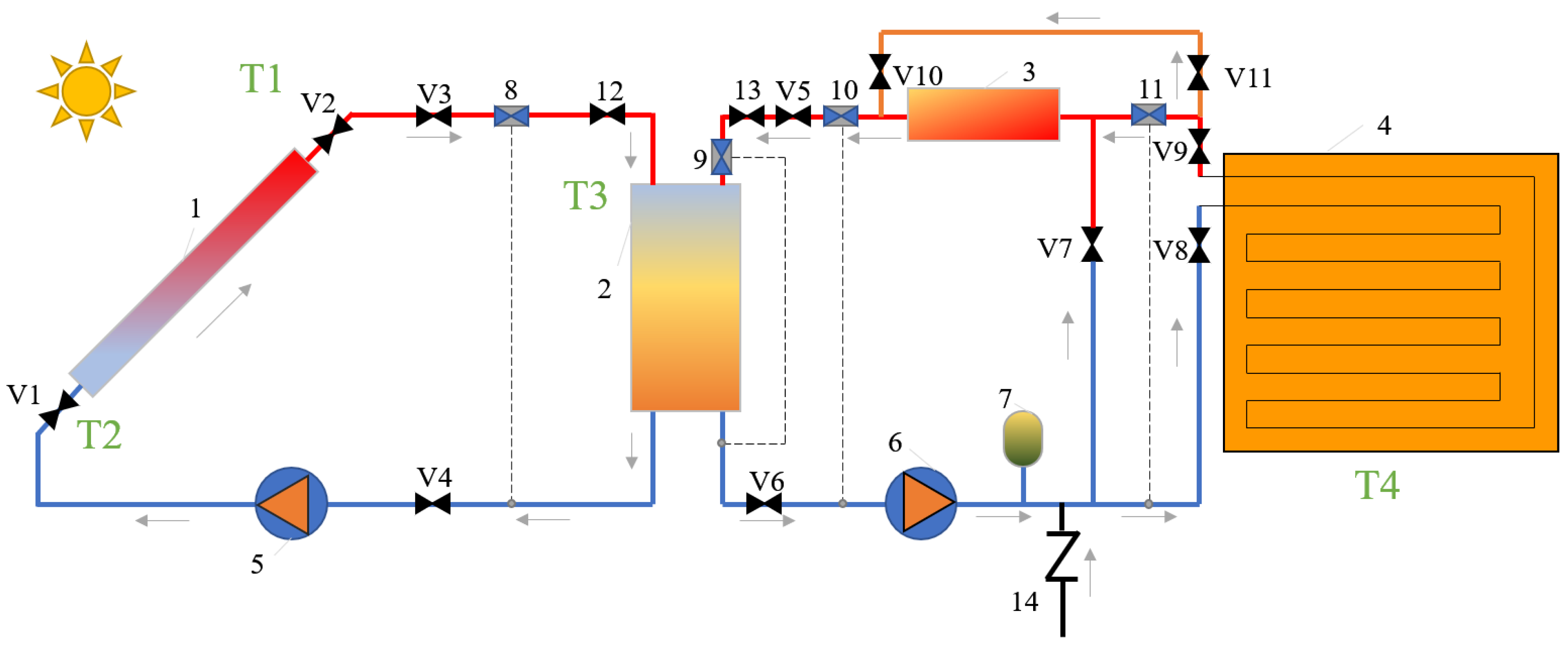
2.3.1. System Theory

A phase-change thermal storage solar heating system is proposed, which is mainly composed of a solar thermal collection system, thermal storage system, and heating terminal (Figure 4). The vacuum tube solar collector converts solar energy into thermal energy. The PCHSD stores solar thermal energy. The heating terminal is the radiation floor
As shown in the figure, the operating principle of this system is as follows:
  • Solar heat storage process: When the water temperature of the outlet of the solar collector (1) meets the requirements, open the valve V1/V2/V3/V4/12 and close other valves. Additionally, start the water pump (5), and PCHSD (2) will begin to store heat.
  • Electric heat-storage process: Open valve V5/V6/V7/13 and close other valves. Electric heater (3) and water pump (6) are turned on to carry out electric heat storage for PCHSD (2).
  • Heating process: Open the valves V5/V6/V8/V9/V10/V11/13, close the other valves, and PCHSD (2) begins to heat the room.

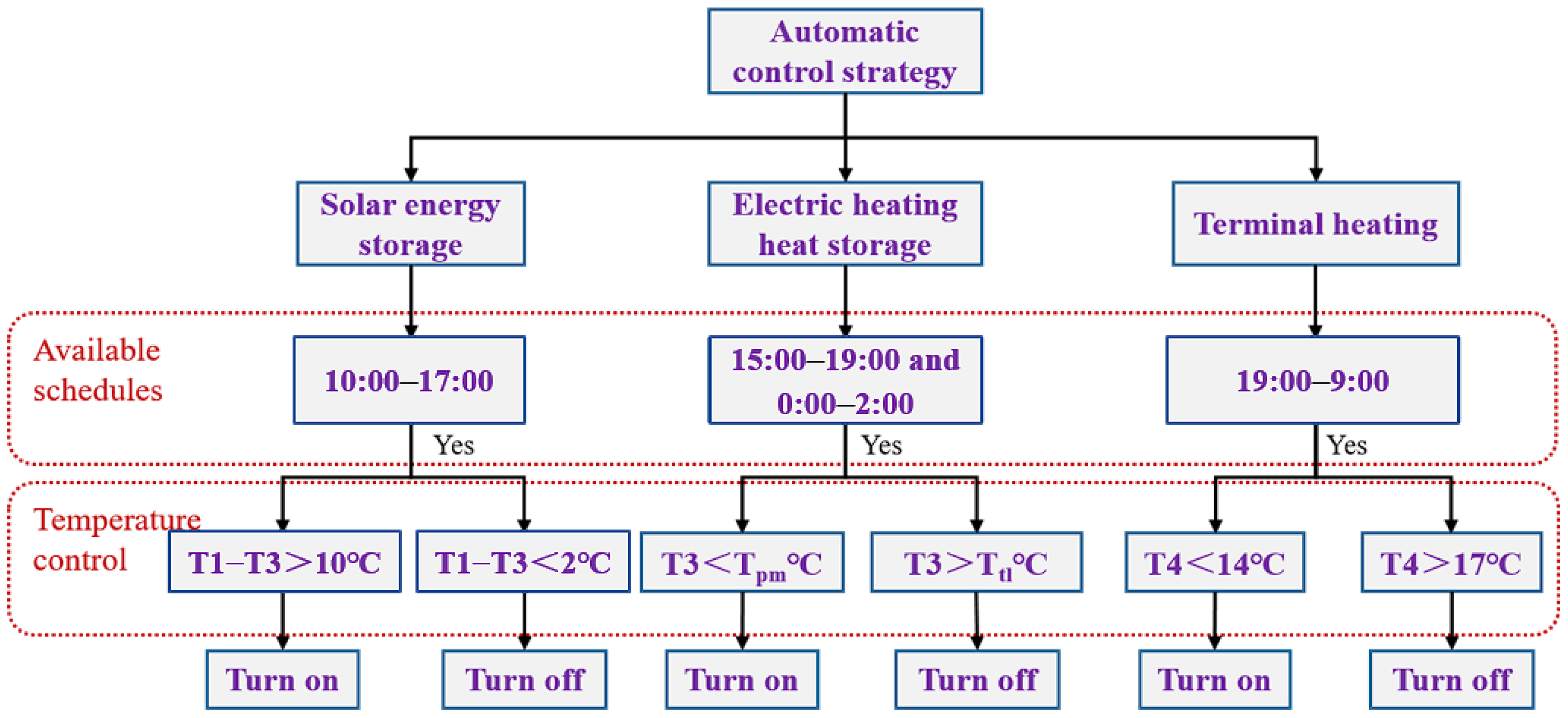
2.3.2. The Automatic Control Strategy

Detailed automatic control strategies are developed for different operating modes, which are integrated with schedule control and temperature control. Figure 5 shows the flow chart of the automatic control strategy. For the schedule control, considering the distribution of solar radiation intensity in a day, the available schedule of solar heat storage is set as 10:00–17:00. Given the lack of solar heat storage during the day and low electricity prices at night, the available schedule of electric heating heat storage is set as 15:00–19:00 and 0:00–2:00. This system is mainly used to meet the heating demand of residents at night; therefore, the available schedule of the phase-change heat release (terminal heating) is 19:00–9:00.
In the case of meeting the available schedule, the temperature control conditions can achieve the adjustment of equipment working conditions. The solar heat storage is adjusted based on the temperature difference between the outlet temperature (T1) of the solar collector and the average temperature of PCHSD (T3). With the increase in solar radiation intensity, the T1 will increase gradually. The temperature difference will also increase gradually with the increase in T1. When the temperature difference is greater than 10 °C, solar heat storage will turn on. When the temperature difference is less than 2 °C, the heat provided by the solar collector is negligible, so solar heat storage is turned off. Electric heat storage is adjusted based on T3. To ensure the complete melting of the PCM after the heat storage process, the electric heat storage is started when T3 is less than the melting temperature of the PCM Tpm. When the T3 is higher than the melting termination temperature of the PCM, the latent heat storage process is completed. Sensible heat storage is followed, and it is limited. Therefore, when latent heat storage ends, the electric heat storage will be turned off. The judgment condition is that the T3 is higher than the preset upper limit temperature (Ttl). The Ttl should generally be higher than the melting termination temperature of the PCM, which was set at 56 °C in this study. Terminal heating is adjusted according to the indoor temperature. According to GB/T50824-2013 [30], the calculated indoor temperature of rural residential buildings in winter is 14 °C. Therefore, when the indoor temperature T4 is greater than 14 °C and higher than 17 °C, terminal heating is turned on and off, respectively.
In a previous study, a laboratory team member set up an experimental platform to analyze the influence of different inlet temperature and flow rate on the heat storage and heat-release performance of the device and verified the accuracy of the simulation with experimental data [27]. Therefore, the optimal system flow selection in this experiment is as follows: heat storage flow is set at 0.144 m3/h and heat-release flow is set at 0.288 m3/h.

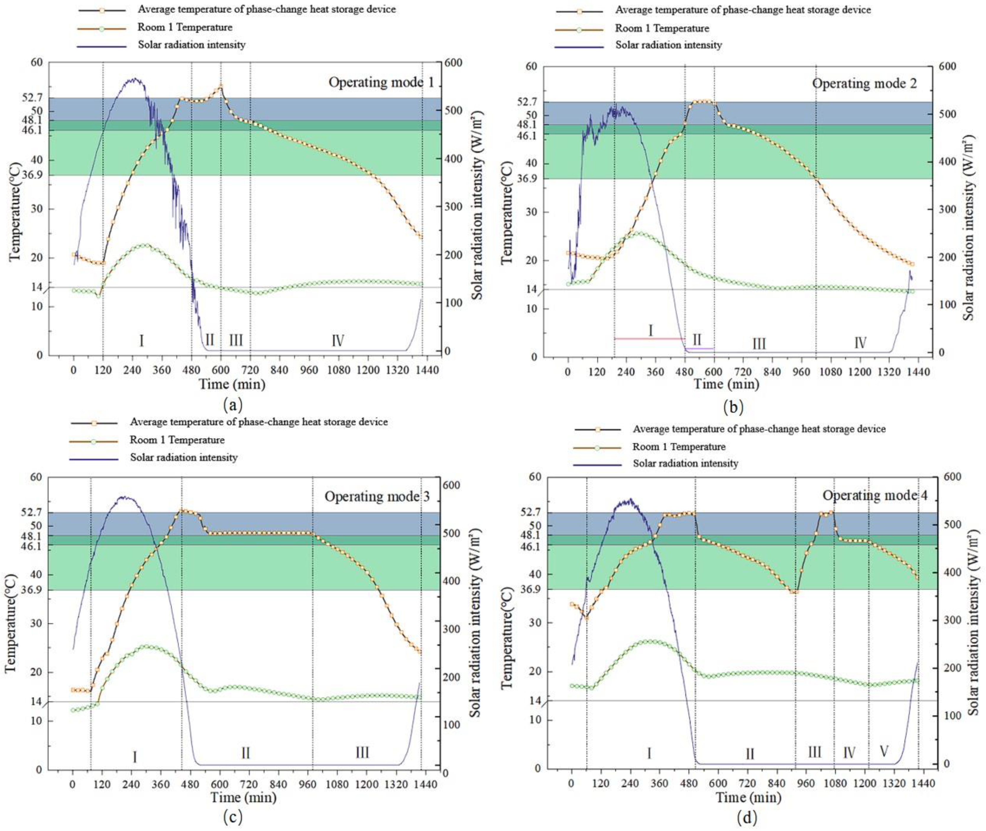
2.3.3. The Operating Mode

Taking into account solar production capacity, heat load characteristics, and electricity price patterns, four operating modes are set up for the heating system (Table 2).
  • Mode 1. When daytime solar radiation is too weak, it is difficult to fill the device with solar energy alone. In this case, electric heat storage is needed to replenish heat after solar heat storage;
  • Mode 2. When daytime solar radiation is too weak and the outdoor temperature is low at night, delay the reheating time of electric heat storage relative to operating mode 1;
  • Mode 3. When the daytime solar energy is sufficient to fill the device, intermittent heating is used at nighttime;
  • Mode 4. When the time-of-use power price (TOU) is implemented, electric heat storage can be used at night to replenish heat for the device.

2.4. Performance Indicators

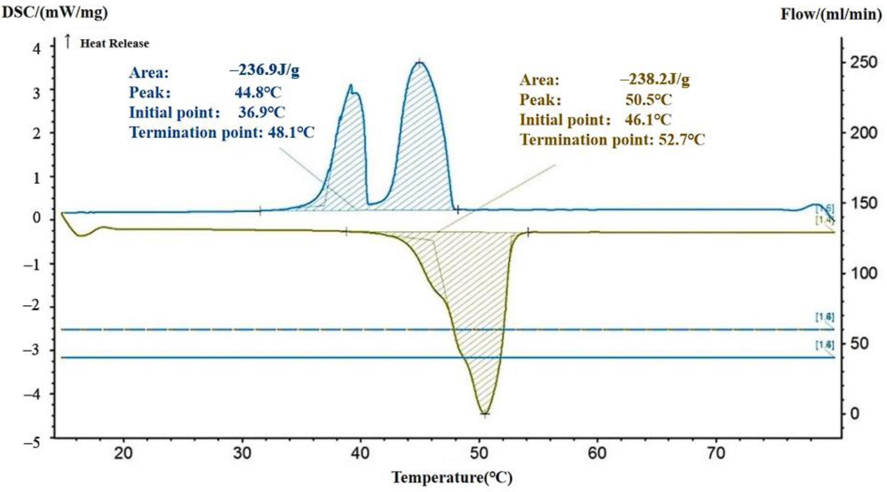
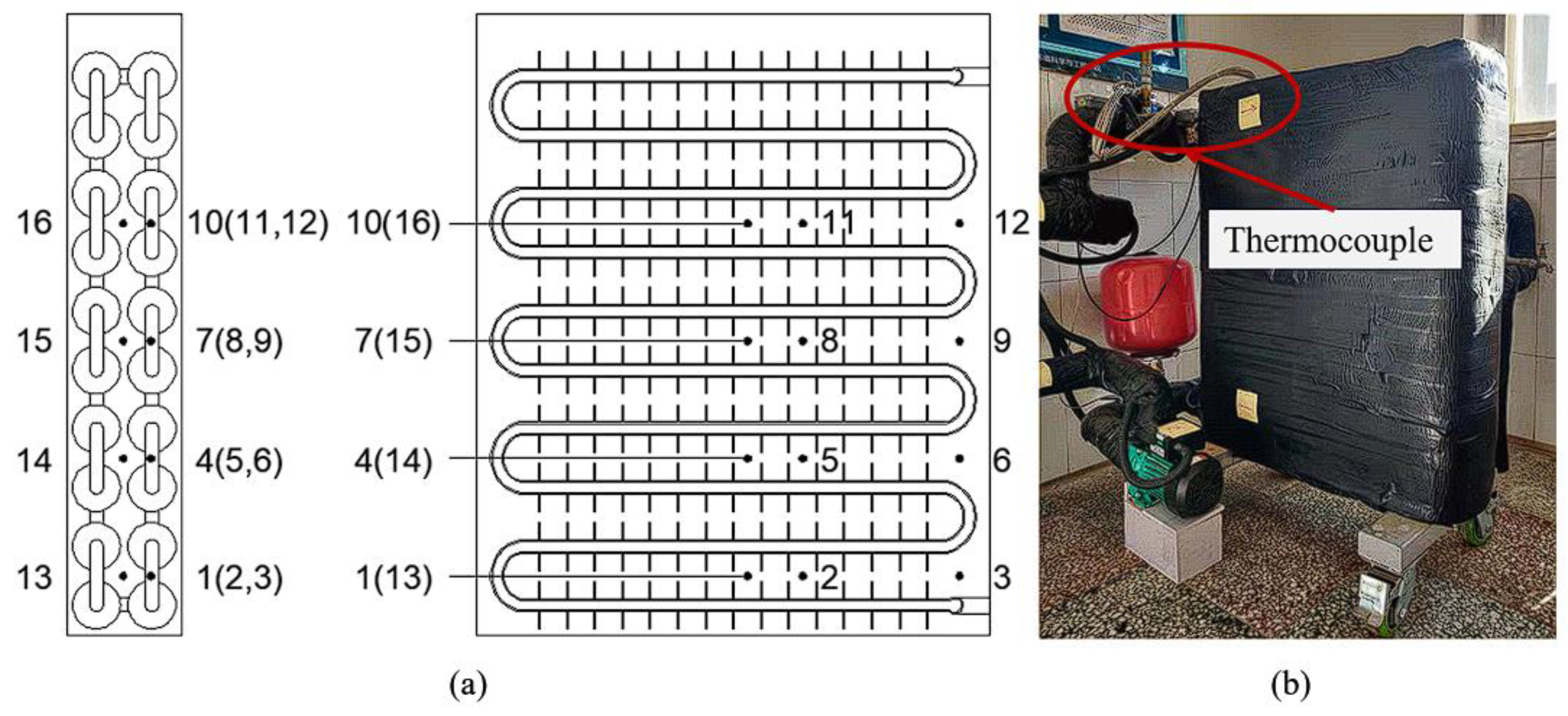
2.4.1. Performance of Phase-Change Heat Storage Device

The performance evaluation indexes of PCHSD include heat storage, heat release, and thermal efficiency within a day, and the calculation method is shown in Equations (3)–(5).
Q s = t b t e ρ c p V f ( T f i T f o ) d t 3600 × 10 3
Q r = t b t e ρ c p V f ( T f o T f i ) d t 3600 × 10 3
η = Q r Q s × 100 %
where Qs is heat storage within a day, MJ; Qr is heat release within a day, MJ; η is the thermal efficiency, %; tb is the start time of storage (release) heat, s; te is the end time of storage (release) heat, s; ρ is the density of water, kg/m3; cp is the constant pressure-specific heat capacity of water, kJ/(kg·K); Vf is the water flow, m3/h; Tfi is the temperature of inlet water, °C; Tfo is the temperature of outlet water, °C.

2.4.2. Renewable Energy Efficiency

In the system, solar energy is stored in phase-change heat storage during the day and used for indoor heating at night. The renewable energy efficiency of the heating system can be expressed by the ratio of solar energy storage to the total heat storage in a day.
φ = Q r s Q s × 100 %
where Qrs is the solar energy storage, MJ.

2.4.3. Indoor Thermal Comfort

According to the standard for the energy-saving design of rural residential buildings (GB/T50824-2013) [30], the indoor thermal comfort threshold of rural residential buildings in winter is 14 °C. When the indoor temperature is below 14 °C, it is considered thermal discomfort. In this paper, the thermal comfort ratio (TCR) was used to evaluate the ability of the heating system to maintain indoor thermal comfort during the test.
T C R = i = 1 q w f i q
w f i = { 1 , 0 , i f i f T T t T < T t
where T is the indoor operating temperature, Tt is the indoor thermal comfort threshold, and q represents the total minutes.

2.4.4. The Economic Indicator

In this study, operating costs are mainly used to evaluate the economy of the heating system, and the main power-consuming equipment in the heating system includes the water pump and the electric heater.
C = 0 t ( P b t + P p t ) E C t M
E C t = { 0.490 ,   i f   0 t < 7 0.331 ,   i f   7 t < 24
where Pb and Pp are the power of the electric heater and water pump, respectively (kW); t is different running times in a day; EC is the corresponding electricity price at the different operating times (CNY/kWh); M is the heating area (m2).

3. The Experiment Setup

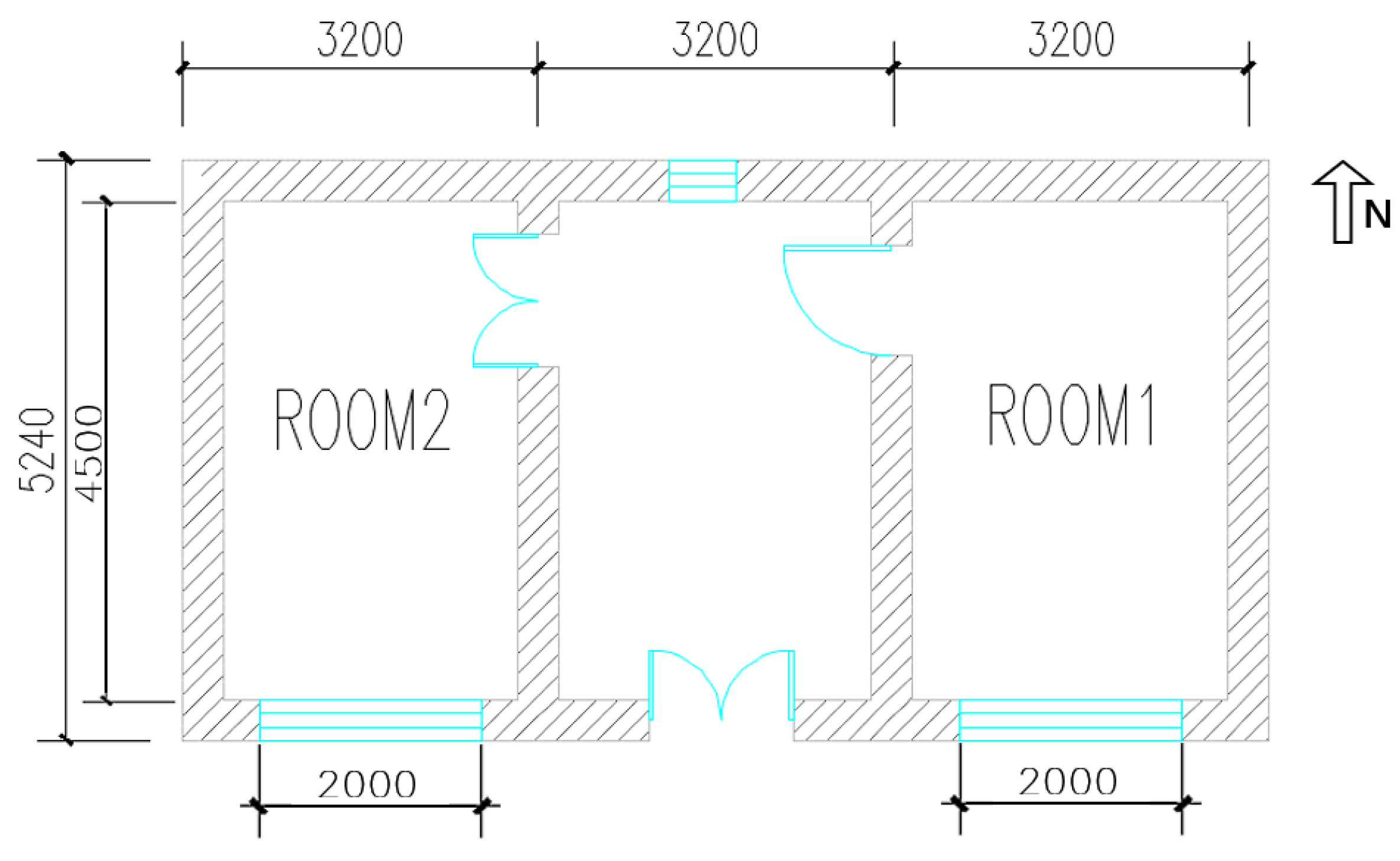
3.1. The Experiment Building

The experiment was carried out at a rural residence in Ninghe district, Tianjin city, China (39.3° N, 117.8° E). Figure 6 shows the plan of the rural residence. The farmhouse faces south and has rooms of the same size on the east and west sides (4.5 m × 3.2 m × 2.7 m). Table 3 shows the building envelope information. In order to more effectively compare the improvement effect of the heating system on indoor thermal comfort, this study set up a control experiment based on these two rooms. The room on the east side will be the experimental room and named room 1. The room on the west side was taken as the control room and named room 2. The heating system only provides heating for the experimental room.

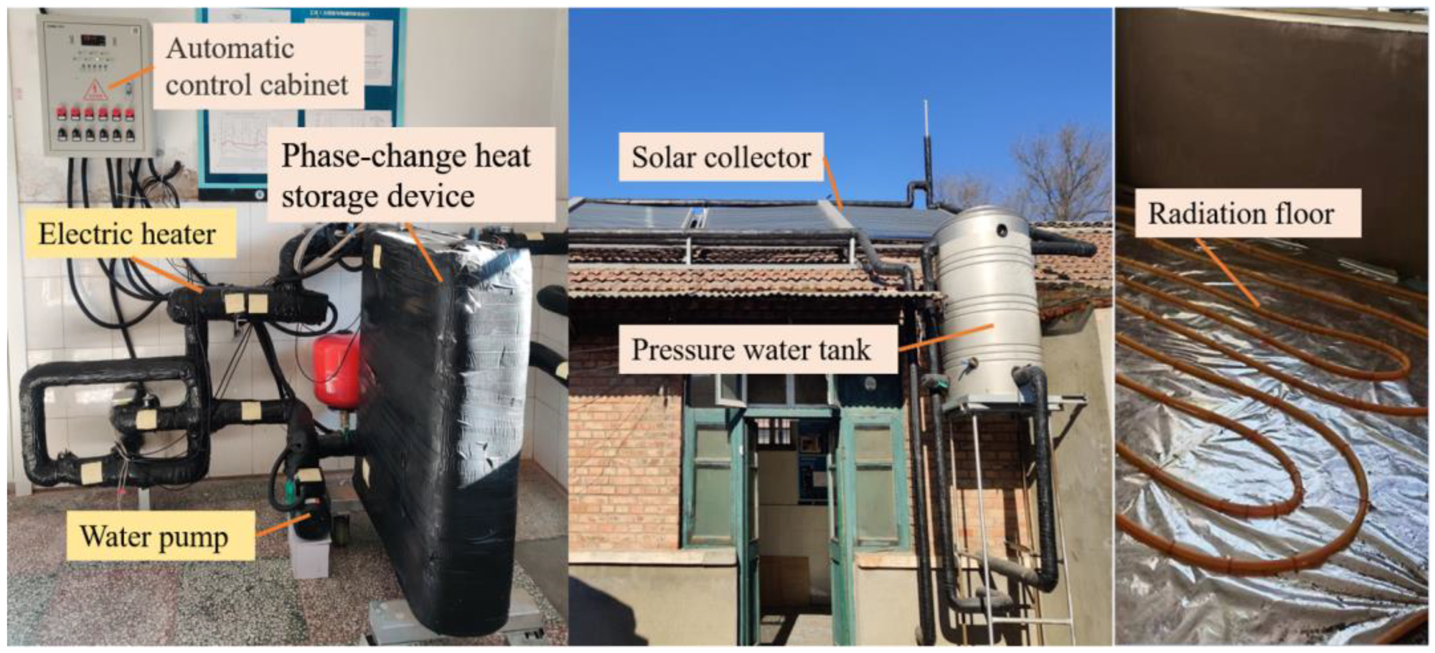
3.2. Experimental Platform for the Heating System

The experimental platform is set up according to the heating system designed in Section 2.2, as shown in Figure 7. The heating system mainly consists of the automatic control cabinet, PCHSD, electric heater, water pump, solar collector, constant pressure water tank, and radiation floor. The automatic control cabinet contains the automatic control policy set in Section 2.2, which enables automatic adjustment of the heating system during the experiment. The electric heater is rated at 2 kW. The water pump is of fixed frequency and the rated power is 0.2 kW. Considering the system form and anti-freezing problem, the vacuum tube solar collector is selected in this experiment. According to the method in Section 2.2, it can be calculated that the area of the solar collector is 11 m2, the azimuth is 2.133°, and the inclination angle is 48.172° (Table 4).

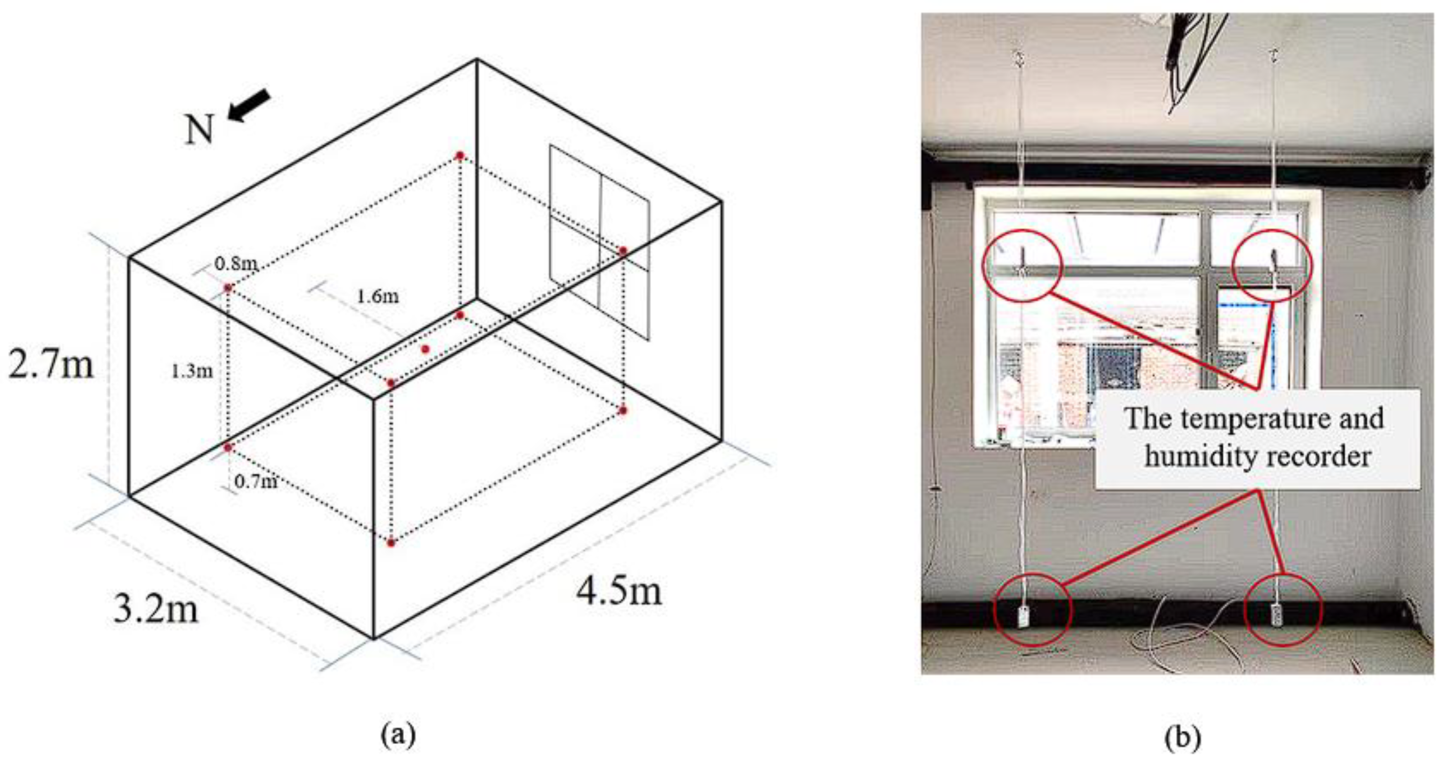
3.3. Experimental Data Collection

The experiment was conducted in Tianjin during the central heating season in January and February, and data from each operating mode for three consecutive days were selected for data collection.
The data to be collected in this experiment include indoor and outdoor environmental parameters, PCHSD parameters, and heating system operating parameters. Outdoor environmental parameters, including solar radiation intensity and air temperature, are obtained by small weather stations. Indoor environmental parameters are mainly air temperature and humidity, which are obtained by using the temperature and humidity recorder. The arrangement of measuring points is shown in Figure 8. In order to test the temperature change in heat-exchange fluid along the path, 16 measuring points were arranged in device (Figure 9). The temperature of these points is obtained using Agilent devices and thermocouples. The operating parameters of the system include flow rate, water temperature, etc., which are obtained by the flow meter and attached temperature recorder. The technical parameters of the main instruments and equipment involved are shown in Table 5.

4. Results and Discussion

4.1. Performance Analysis of Device

This section analyzes the thermal performance of PCHSD under different operating modes. Figure 10 shows the temperature variation in the device, the indoor temperature and solar radiation intensity during the test under four operating modes.

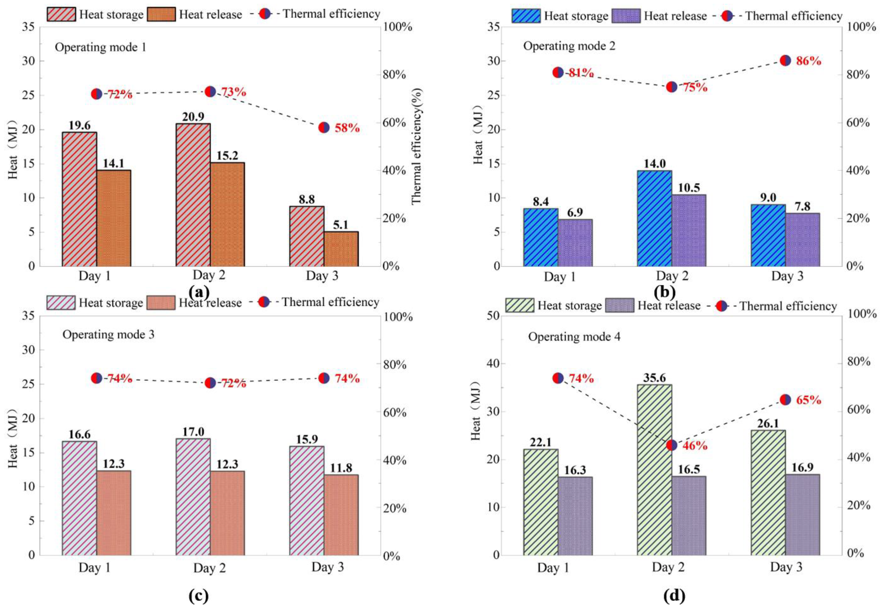
4.1.1. The Heat Storage

The initial and final melting temperatures of phase-change materials are 46.1 °C and 52.7 °C, respectively. For mode 1, the solar heat storage stage (Stage Ⅰ) starts from 120 min to 480 min. Sensible heat storage occurs in the period from 120 min to 380 min. The phase-change material in this stage is a pure solid. At this time, the phase-change material is heated by means of heat conduction. With the rapid increase in temperature, the heat storage mode of materials gradually changed from sensible heat to latent heat. The temperature change trend becomes steeper. In the latent heat storage stage, fin and tube wall temperature rise faster, and phase-change materials near these places first undergo the phase-change process. After the phase change, the liquid material moves upward due to natural convection, which enhances the heat transfer effect of the device, so the heat storage capacity of the device is significantly improved [27]. At 480 min, the solar heat storage process ends, and the average temperature in the device is close to the melting termination temperature of PCM 52.7 °C. Then, electric heat storage is used to supplement heat and ends at 600 min (Stage Ⅱ). Before the end of this stage, the temperature of each measuring point inside the device reached more than 52.7 °C, indicating that phase-change material is in the stage of sensible heat storage of pure liquid, further heating the results with a significant temperature rise. Through the observation port, it can be seen that the phase-change material is fully melted. Additionally, by monitoring the temperature of each point inside the outlet device and the temperature change in the inlet and outlet, the phase-change process of the phase-change material is judged to be complete.
For operating mode 2, compared with operating mode 1, its operation strategy only changes the continuity of the night heating process. As can be seen from the figure, the peak solar radiation intensity on the test day is 50 w/m2 lower than that in operation mode 1, and the distribution of solar radiation intensity in daytime is not uniform. The solar heat storage process starts at 180 min, nearly an hour later than that in operating mode 1. Therefore, the process of daytime heat storage is closely related to the intensity of solar radiation. The average internal temperature reached 46.1 °C after 480 min operation of the system, and the phase-change material only completed sensible heat storage. During this period, because the temperature of the outlet of the solar collector reaches the peak and cannot rise further, and the thermal conductivity of pure PCM is low, the limitation of temperature rise has an amplified effect on the weakening of the heat storage process. Then, the electric heating was turned on for heat storage. After two hours of electric heating and heat replenishment, the internal temperature of the system reached 52.7 °C, which proved that the system had completed latent heat storage. For operating mode 3, solar radiation is sufficient and uniform. A total of 276 min after the solar heat storage began, the average temperature of each measuring point in the device reached about 46.1 °C, and then the system ended the sensible heat storage stage and continued to the latent heat storage stage. When the system runs for 440 min, the temperature difference between the outlet water temperature of the solar collector and the temperature inside the device is less than 2 °C, which ends the solar heat storage stage (Stage Ⅰ). The average temperature of each measuring point in the device exceeds 52.7 °C, and the phase-change material melting effect was relatively better.
For operating model 4, there is electric heat storage at night, so the water temperature in PCHSD reaches 32.5 °C before the heat storage process begins. At 400 min, the temperature of each measuring point in the device reached 52.7 °C. After that, due to the limited increase in the outlet water temperature of the solar collector, the water temperature in the device slowly increased and was finally maintained at about 52.7 °C. The phase-change material was completely melted, and the device had sufficient heat storage. In general, in the case of sufficient solar radiation, solar energy alone can meet the heat storage requirements of the device. If solar radiation is not sufficient, adding electric heat storage can also store enough heat before the system turns on the heating circuit.

4.1.2. The Heat Release

For the heat-release stage, the initial and final solidification temperatures of PCM are 48.1 °C and 36.9 °C, respectively. For operating mode 1, the opening condition of intermittent heating is that the indoor temperature is below 14 °C after heat storage. The PCHSD first performs sensible heat release, which is dominated by convection heat transfer and has a large heat-transfer coefficient. The temperature of the phase-change material drops rapidly from 54.6 °C to 48.1 °C within 100 min after the heating circuit is opened. Then, the device enters the latent heat-release stage. With the decrease in the liquid phase ratio of phase-change materials, the natural convection gradually weakens. In addition, the heat transfer effect weakens with the solidification of the PCM finned tube. Therefore, the temperature drop in PCM is slower, and it takes 522 min from the beginning to the end of solidification. At the same time, the indoor temperature increased from 12.5 °C to 15.5 °C, meeting the control requirements of the indoor temperature of 14 °C. In the process of night heating in operating mode 2, the latent heat-release time of phase-change material in the device is 360 min, 120 min faster than that in operating mode 1. This indicates that continuous heating will cause rapid loss of internal heat in the device, and after the end of latent heat release, it cannot meet the subsequent overnight heating demand. Intermittent heating can release the heat in the unit evenly when the room needs it, which can ensure the need for overnight heating. Operating mode 3 is intermittent heating. The temperature in the device was maintained at the initial phase-change solidification temperature of 48.1 °C for about 435 min. This shows that PCHSD can maintain the internal temperature at a high level through its good insulation performance during the period when heating is not started. It reflects the advantages of the combination of intermittent heating and PCHSD, which can maintain the internal temperature of the device at a certain level and provide conditions for subsequent heating. After the heating circuit is turned on, the indoor temperature increases from 14.5 °C to 15.5 °C. The reason for the limited temperature increase in this process is that the thermal inertia of the building envelope is closely related to the change in the indoor thermal environment during intermittent heating [26]. Moreover, the radiant floor used in the experiment has high heat-transfer resistance and high thermal inertia, and some of the heat is used to preheat the floor.
For operating mode 4, PCHSD releases heat for the first time from 520 min to 890 min, and the temperature inside the device decreases from 48.1 °C to below 36.9 °C, while the indoor temperature increases to 19.8 °C. Electric heat storage is then used to assist heat storage at night, and the temperature inside the device continues to rise. A total of 120 min later, the average temperature of the phase-change material reached 52.7 °C, and the phase-change material completely melted again. Some of the latent heat was stored in the device. The heating circuit was then turned on to reverse the downward trend of the indoor temperature and maintain the indoor temperature above 17 °C all night. At 9 a.m. the next day, the temperature in the device was still above 33 °C, which reduced the heat required for the next day’s heat storage.

4.1.3. Thermal Efficiency

Figure 11 shows the heat storage, the heat release, and the thermal efficiency of PCHSD under four operating modes (obtained according to Equations (3)–(5)). The thermal efficiency varies with operating modes but is higher than 46.2% and even as high as 85.8% under all operating modes.
The thermal efficiency of PCHSD is determined by heat storage and heat release. Under the same heat storage conditions, the greater the heat release, the higher the thermal efficiency of the device. In the actual heating system, heat release is constrained by the heating demand. As can be seen from Figure 11, the thermal efficiency of the device in mode 2 is higher than that in other operating modes. The main reason is that the heating system uses continuous heating in this mode, while using intermittent heating in other modes. The heating demand for continuous heating is greater than that of intermittent heating. Therefore, in mode 2, the heat release in the device is more complete, and the corresponding thermal efficiency is relatively high.
For operating mode 4, the thermal efficiency on the second test day was significantly reduced at only 46.2%. The main reason is that there is excess heat storage relative to heating demand in this operating mode. Intermittent heating in this mode results in the insufficient release of heat during the day, which is called daily heat loss. The heat not released the day before is still stored in the device since the system is in continuous operation and PCHSD has good insulation performance.

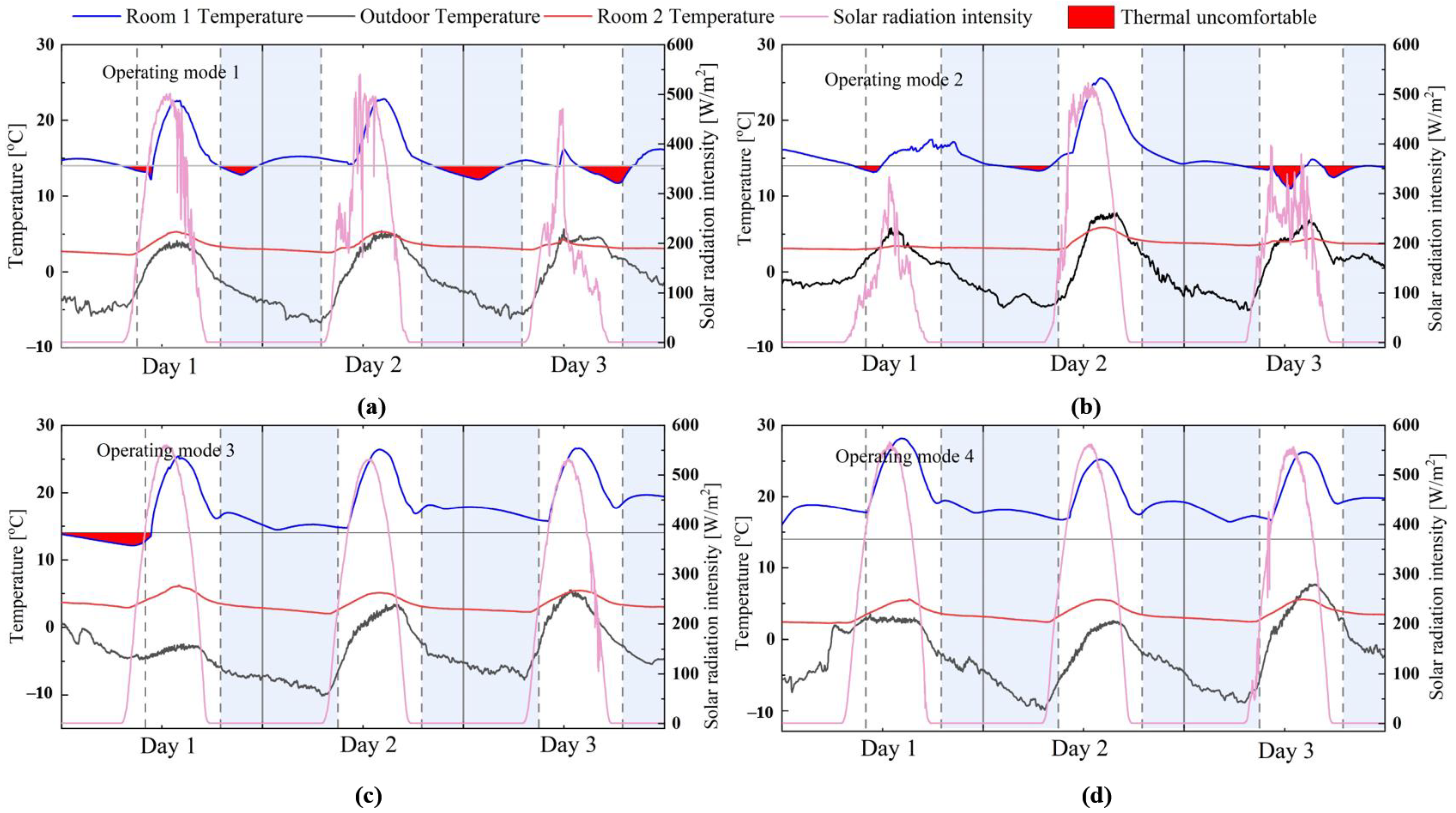
4.2. Indoor Thermal Comfort

This section evaluates the effect of the heating system on maintaining indoor thermal comfort by comparing two rooms. Figure 12 shows the variation in indoor and outdoor environmental parameters under four operating modes. In order to display the thermal comfort effect more directly, the period when the indoor temperature is lower than 14 °C, that is, the period in thermal discomfort, is filled with a red color.
As can be seen from Figure 12, the thermal comfort ratios of the four operating modes are 66.4%, 65.9%, 85.1%, and 100%, respectively. The amount of solar radiation not only affects the thermal storage performance of PCHSD, but also affects the indoor thermal comfort in the daytime. At the same time, this effect is amplified by the small thermal conductivity of PCM. Insufficient solar radiation during the day is the main reason for the low thermal comfort ratio of modes 1 and 2.
As can be seen from Figure 12, there may be thermal discomfort periods both day and night. During the day, the indoor thermal comfort is maintained mainly by passive solar heat generation, so the indoor temperature may be lower than the thermal comfort temperature when the solar radiation intensity is weak. For intermittent heating operating modes (modes 1 and 3), there is a period of thermal discomfort due to the need to preheat the room temperature and the radiant floor at the initial stage of each heating start-up. The subsequent experimental research needs to improve the material of the radiant floor of the heating terminal into smaller and lower amounts of material with thermal inertia to make its surface temperature change more sensitively and adjust the indoor temperature in a more timely manner.

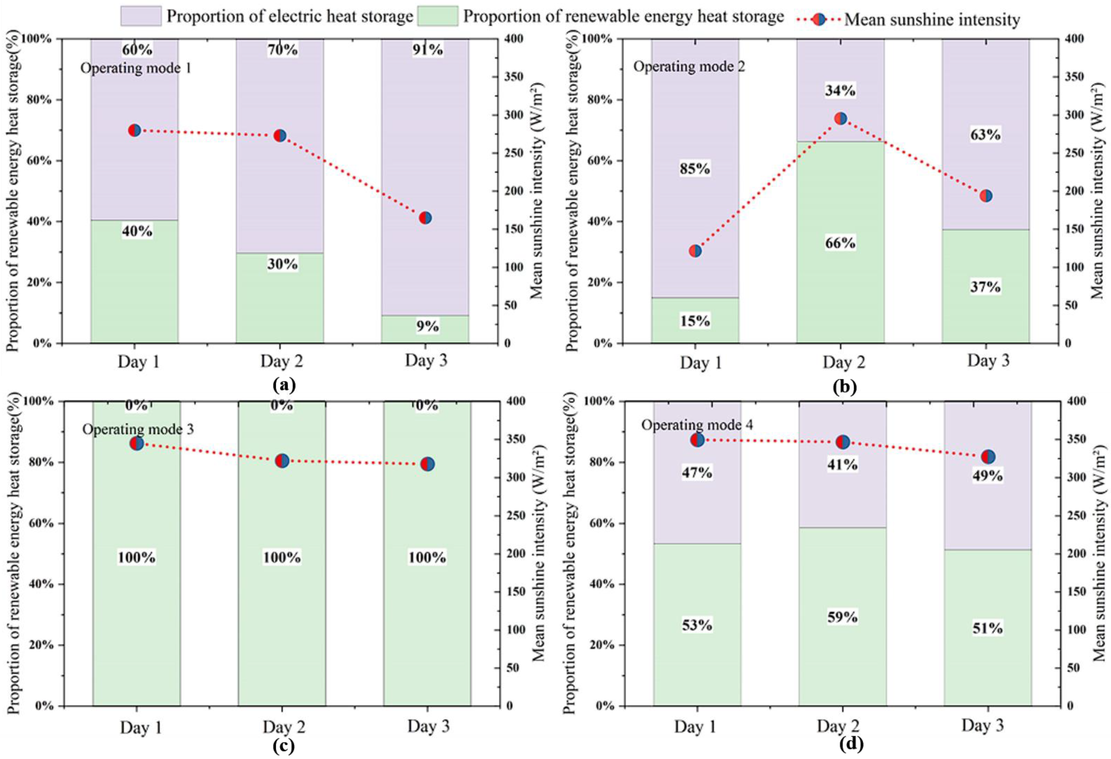
4.3. Renewable Energy Efficiency
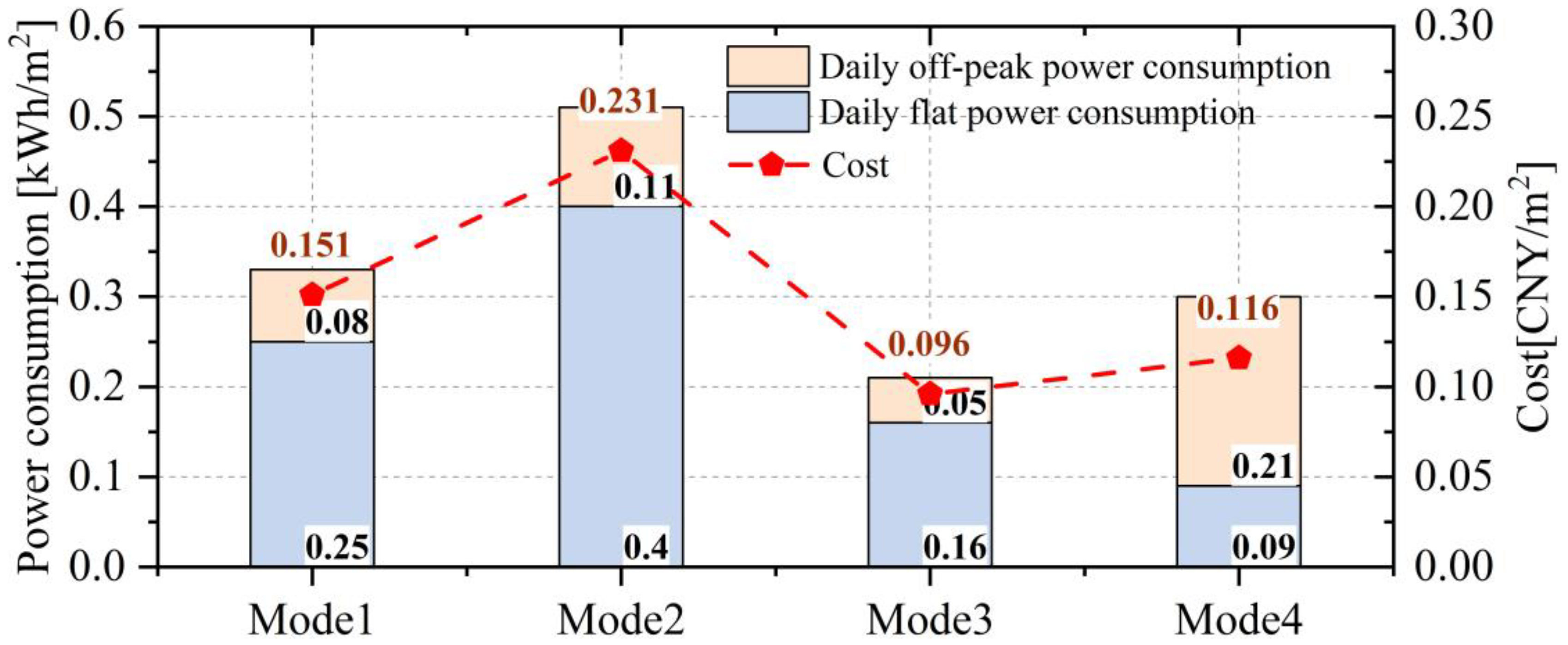
Figure 13 shows the relationship between solar radiation intensity and renewable energy efficiency. As can be seen from the figure, the renewable energy efficiency of operating mode 3 is 100% on all test days because electric heat storage is not involved. For other operating modes, renewable energy efficiency is positively correlated with solar radiation density; therefore, the uncertainty is large, and the fluctuation range is 9%–100%.

4.4. System Economy

In solar heating systems, the ideal phase-change material needs to have the advantages of high latent heat, high density, high thermal conductivity, stable performance, good compatibility with the container and low price. Paraffin is an organic phase-change material with moderate price and good heat storage performance. Therefore, the phase-change material used in this system is paraffin. According to Section 2.1, it is known from the above that 163 kg PCM is used in the system. The average unit price of PCM used in this experiment is 50 CNY/kg, and the calculated cost of the phase-change material is CNY 8150.
According to the power grid sales price list of Ninghe District, Tianjin, the peak–valley TOU price of household electricity in Ninghe is divided into a flat segment and a trough segment. When less than 1 kV, the flat segment price and trough price are 0.490 CNY/kWh and 0.331 CNY/kWh, respectively. According to Equations (9) and (10), the operating cost of the system under four operating modes can be calculated.
Figure 14 shows the daily power consumption and operating cost under four operating modes. The average daily operating cost of operating mode 1 to operating mode 4 is 0.151 CNY/m2, 0.231 CNY/m2, 0.096 CNY/m2, and 0.116 CNY/m2, respectively. According to economic indicators, the operating cost of the heating system is mainly related to the power of water pumps and electric heaters. Operating mode 3 does not need to turn on electric heat storage, so it consumes the least power and has the best economy. Operating mode 2 is daytime electric heat storage and continuous heating at night. In this mode, the pump and electric heater run for a long time, so the corresponding system power consumption and operating costs are the highest. Operating mode 1 is daytime electric heat storage, while operating mode 4 can use the off-peak electricity price for electric heat storage at night, so its operating cost is slightly lower than operating mode 1.
To more intuitively display the economic level of the heating system, it is compared with several other major clean-heating technologies (Figure 15). The operating cost of common clean-heating technologies is between 13 and 35 CNY/(m2·a), and the average cost is 24.1 CNY/(m2·a). Based on the test data, the annual average operating cost of the system under different operating modes is 17.53 CNY/(m2·a), which can be reduced by about 27.3% compared with the average operating cost of the existing clean heating technology, showing significant economy.

5. Conclusions

A phase-change thermal storage solar heating system is proposed for rural areas in northern China. The system was applied to a farmhouse in Tianjin, and its practical application effect was tested under four operating modes. Finally, the operating performance of the system is evaluated from four aspects: renewable energy efficiency, PCHSD performance, indoor thermal comfort, and economy. The main conclusions are as follows:
  • The phase-change heat storage device shows good thermal performance in the practical application of the heating system. The thermal efficiency varies with operating modes, but it is higher than 46.2% and even as high as 85.8% under all operating modes.
  • The low thermal conductivity of phase-change materials seriously affects the heat storage efficiency. In this experiment, fins are added to the device to improve the poor thermal conductivity of the system and materials. In subsequent studies, phase-change materials can also be made into phase-change composites by adding expanded graphite, multilayer graphene and nanoparticles with high thermal conductivity, which can improve the heat storage rate of materials on the basis of ensuring energy storage efficiency.
  • The experimental room maintained better thermal comfort performance under four operating modes, and the thermal comfort ratio in operating modes 1–4 was 67%, 66%, 85.1%, and 100%, respectively. The combination of a good-performance heat storage device and a reasonable operating mode is a necessary condition for the heating system to use intermittent heating.
  • The renewable energy efficiency of the system is positively correlated with the solar radiation intensity, which fluctuates between 9% and 100%. When there is enough solar energy during the day (operating modes 3 and 4), solar energy can be used as the only heat source of the system to ensure indoor thermal comfort.
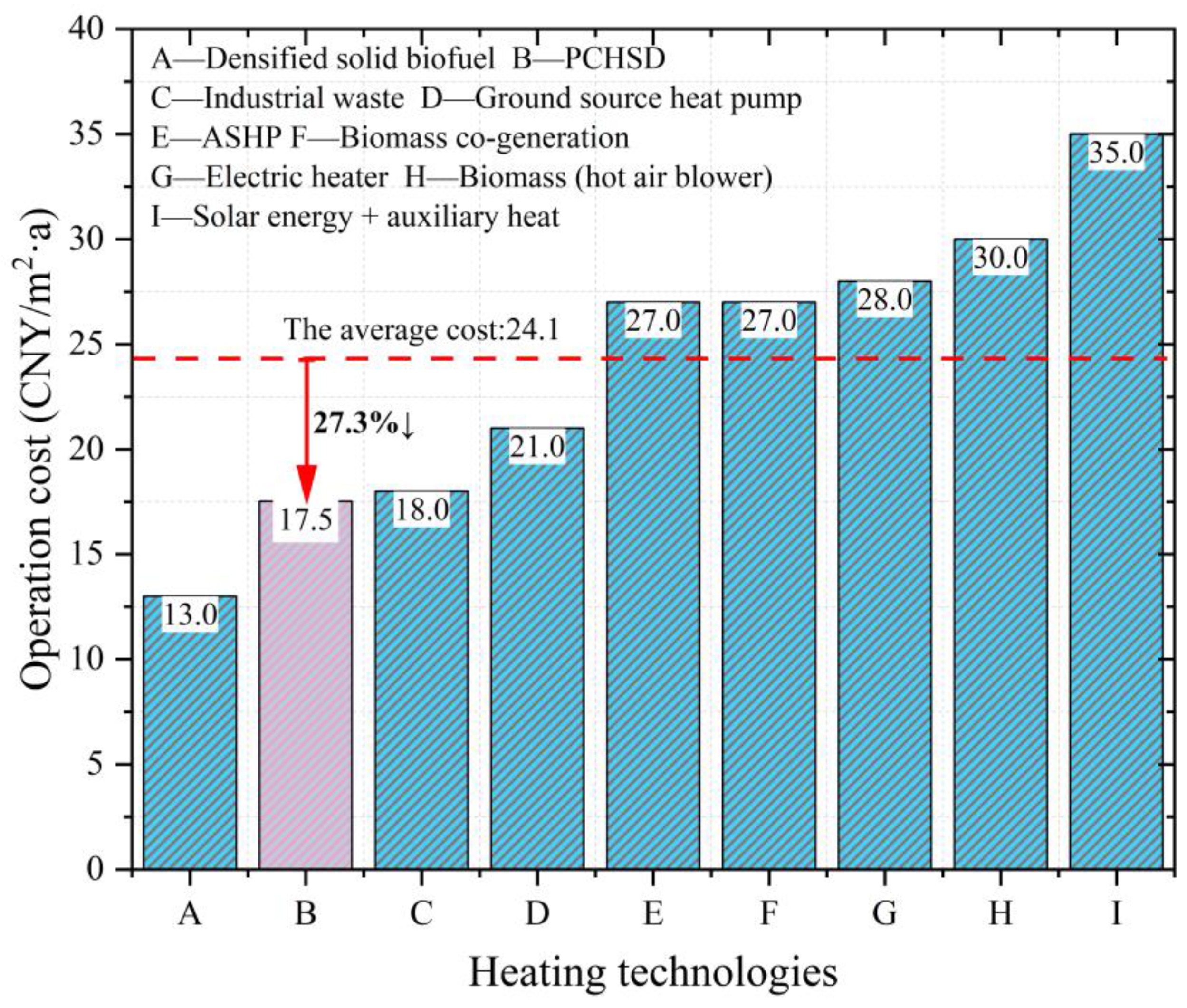
  • The combination of intermittent heating and a phase-change heat storage device can ensure better heating effect, and the economic advantage of this system is very obvious. The annual average operating cost of the system under different operating modes is 17.53 CNY/(m2·a), which can be reduced by about 27.3% compared with the average level of the existing clean-heating technology.

Author Contributions

Writing—original draft, J.Z.; Writing—review & editing, R.W.; Supervision, S.L. All authors have read and agreed to the published version of the manuscript.

Funding

This work was supported by National Natural Science Foundation of China (Grant No. 51978451).

Institutional Review Board Statement

Not applicable.

Informed Consent Statement

Not applicable.

Data Availability Statement

Not applicable.

Acknowledgments

This paper would like to thank our research group for the structural research and design of phase change heat storage device.

Conflicts of Interest

The authors declare no conflict of interest.

Nomenclature

ATSSThe active thermal storage system
DSCDifferential scanning calorimetry
PCMPhase change material
PTSSThe passive thermal storage system
PCHSDPhase change heat storage device
TESThermal energy storage
TOUTime-of-use
TCRThe thermal comfort ratio
Symbols
cpHeat capacity at constant pressure, kJ·kg−1·K−1
QsHeat storage, MJ
QrHeat release, MJ
QrsRenewable energy heat storage, MJ
tbStart time of storage (release) heat, s
teEnd time of storage (release) heat, s
TfiThe temperature of inlet water, °C
TfoThe temperature of outlet water, °C
TpmThe peak melting temperatures of PCM, °C
TpsThe peak solidification temperatures of PCM, °C
TtlThe upper temperature limit of electric heater, °C
VfWater flow, m3/h
Greek symbols
φThe efficiency of renewable energy of the phase change heat storage device, %
σThermal efficiency of phase change heat storage device, %
ρThe density of water, kg/ m³

References

  1. Tschopp, D.; Tian, Z.; Berberich, M.; Fan, J.; Perers, B.; Furbo, S. Large-scale solar thermal systems in leading countries: A review and comparative study of Denmark, China, Germany and Austria. Appl. Energy 2020, 270, 114997. [Google Scholar] [CrossRef]
  2. Stritih, U.; Tyagi, V.; Stropnik, R.; Paksoy, H.; Haghighat, F.; Joybari, M. Integration of passive PCM technologies for net-zero energy buildings. Sustain. Cities Soc. 2018, 41, 286–295. [Google Scholar] [CrossRef]
  3. Pielichowska, K.; Pielichowski, K. Phase change materials for thermal energy storage. Prog. Mater. Sci. 2014, 65, 67–123. [Google Scholar] [CrossRef]
  4. Alva, G.; Liu, L.K.; Huang, X.; Fang, G. Thermal energy storage materials and systems for solar energy applications. Renew. Sustain. Energy Rev. 2017, 68, 693–706. [Google Scholar] [CrossRef]
  5. Khedher, N.B.; Bantan, R.; Kolsi, L.; Omri, M. Performance investigation of a vertically configured LHTES via the combination of nano-enhanced PCM and fins: Experimental and numerical approaches. Int. Commun. Heat Mass Transf. 2022, 137, 106246. [Google Scholar] [CrossRef]
  6. Aurangzeb, M.; Noor, F.; Qamar, A.; Shah, A.; Kumam, P.; Shah, Z.; Shutaywi, M. Investigation of enhancement in the thermal response of phase change materials through nano powders. Case Stud. Therm. Eng. 2022, 29, 101654. [Google Scholar] [CrossRef]
  7. Zahid, I.; Farooq, M.; Farhan, M.; Usman, M.; Qamar, A.; Imran, M.; Alqahtani, M.; Anwar, S.; Sultan, M.; Javaid, M. Thermal Performance Analysis of Various Heat Sinks Based on Alumina NePCM for Passive Cooling of Electronic Components: An Experimental Study. Energies 2022, 15, 8416. [Google Scholar] [CrossRef]
  8. Shaukat, R.; Anwar, Z.; Imran, S.; Noor, F.; Qamar, A. Numerical Study of Heat Transfer Characteristics of mPCM Slurry During Freezing. Arab. J. Sci. Eng. 2021, 46, 7977–7988. [Google Scholar] [CrossRef]
  9. Guan, Y.; Wang, T.; Tang, R.; Hu, W.; Guo, J.; Yang, H.; Zhang, Y.; Duan, S. Numerical study on the heat release capacity of the active-passive phase change wall affected by ventilation velocity. Renew. Energy 2020, 150, 1047–1056. [Google Scholar] [CrossRef]
  10. Beemkumar, N.; Yuvarajan, D.; Arulprakasajothi, M.; Elangovan, K.; Arunkumar, T. Control of room temperature fluctuations in the building by incorporating PCM in the roof. J. Therm. Anal. Calorim. 2021, 143, 3039–3046. [Google Scholar] [CrossRef]
  11. Gholamibozanjani, G.; Farid, M. A comparison between passive and active PCM systems applied to buildings. Renew. Energy 2020, 162, 112–123. [Google Scholar] [CrossRef]
  12. Khedher, N.B. Numerical Study of the Thermal Behavior of a Composite Phase Change Material (PCM) Room. Eng. Technol. Appl. Sci. Res. 2018, 8, 2663–2667. [Google Scholar] [CrossRef]
  13. Chen, C.; Ling, H.; Zhai, Z.; Li, Y.; Yang, F.; Han, F.; Wei, S. Thermal performance of an active-passive ventilation wall with phase change material in solar greenhouses. Appl. Energy 2018, 216, 602–612. [Google Scholar] [CrossRef]
  14. Stathopoulos, N.; El Mankibi, M.; Issoglio, R.; Michel, P.; Haghighat, F. Air–PCM heat exchanger for peak load management: Experimental and simulation. Sol. Energy 2016, 132, 453–466. [Google Scholar] [CrossRef]
  15. Qiao, X.; Kong, X.; Li, H.; Wang, L.; Long, H. Performance and optimization of a novel active solar heating wall coupled with phase change material. J. Clean. Prod. 2020, 250, 119470. [Google Scholar] [CrossRef]
  16. Lu, S.; Xu, B.; Tang, X. Experimental study on double pipe PCM floor heating system under different operation strategies. Renew. Energy 2020, 145, 1280–1291. [Google Scholar] [CrossRef]
  17. Zhou, Z.; Liu, J.; Wang, C.; Huang, X.; Gao, F.; Zhang, S.; Yu, B. Research on the application of phase-change heat storage in centralized solar hot water system. J. Clean. Prod. 2018, 198, 1262–1275. [Google Scholar] [CrossRef]
  18. El Khadraoui, A.; Bouadila, S.; Kooli, S.; Farhat, A.; Guizani, A. Thermal behavior of indirect solar dryer: Nocturnal usage of solar air collector with PCM. J. Clean. Prod. 2017, 148, 37–48. [Google Scholar] [CrossRef]
  19. Xu, L.; Luo, C.; Cai, J.; Ji, J.; Dai, L.; Yu, B.; Huang, S. Modeling and analysis of a dual-channel solar thermal storage wall system with phase change material in hot summer and cold winter area. Build. Simul. 2022, 15, 179–196. [Google Scholar] [CrossRef]
  20. Singh, R.; Mathur, J.; Bhandari, M. Analysis of different operating strategies of thermal energy storage with radiant cooling system. Int. J. Energy Res. 2021, 45, 6174–6197. [Google Scholar] [CrossRef]
  21. Lin, K.; Zhang, Y.; Xu, X.; Di, H.; Yang, R.; Qin, P. Experimental study of under-floor electric heating system with shape-stabilized PCM plates. Energy Build. 2005, 37, 215–220. [Google Scholar] [CrossRef]
  22. Cheng, W.; Xie, B.; Zhang, R.; Xu, Z.; Xia, Y. Effect of thermal conductivities of shape stabilized PCM on under-floor heating system. Appl. Energy 2015, 144, 10–18. [Google Scholar] [CrossRef]
  23. Pupeikis, D.; Burlingis, A.; Stankevicius, V. Required Additional Heating Power Of Building During Intermitted Heating. J. Civ. Eng. Manag. 2010, 16, 141–148. [Google Scholar] [CrossRef] [Green Version]
  24. Li, Y.; Long, E.; Zhang, L.; Dong, X.; Wang, S. Energy-saving potential of intermittent heating system: Influence of composite phase change wall and optimization strategy. Energy Explor. Exploit. 2020, 39, 426–443. [Google Scholar] [CrossRef]
  25. Xu, B.; Zhou, S.; Hu, W. An intermittent heating strategy by predicting warm-up time for office buildings in Beijing. Energy Build. 2017, 155, 35–42. [Google Scholar] [CrossRef]
  26. Wang, Z.; Lin, B.; Zhu, Y. Modeling and measurement study on an intermittent heating system of a residence in Cambridgeshire. Build. Environ. 2015, 92, 380–386. [Google Scholar] [CrossRef]
  27. Lu, S.; Zhai, X.; Gao, J.; Wang, R. Performance optimization and experimental analysis of a novel low-temperature latent heat thermal energy storage device. Energy 2022, 239, 122496. [Google Scholar] [CrossRef]
  28. Ministry of Housing and Urban-Rural Development of the People’s Republic of China. Technical Specification for Radiant Heating and Cooling; Ministry of Housing and Urban-Rural Development of the People’s Republic of China: Beijing, China, 2012.
  29. Ministry of Housing and Urban-Rural Development of the People’s Republic of China. Technical Standard for Solar Heating Engineering; Ministry of Housing and Urban-Rural Development of the People’s Republic of China: Beijing, China, 2019.
  30. Ministry of Housing and Urban-Rural Development of the People’s Republic of China. Announcement on the Release of the National Standard “Design Standard for Energy Efficiency of Rural Residential Buildings”; Ministry of Housing and Urban-Rural Development of the People’s Republic of China: Beijing, China, 2014.
  31. Zhang, Z.; Zhou, Y.; Zhao, N.; Li, H.; Tohniyaz, B.; Mperejekumana, P.; Hong, Q.; Wu, R.; Li, G.; Sultan, M.; et al. Clean heating during winter season in Northern China: A review. Renew. Sustain. Energy Rev. 2021, 149, 111339. [Google Scholar] [CrossRef]
Figure 1. Schematic diagram of device. (a) Overall shape (b) Left view (c) Top view (d) Bottom view (e) Interior view 1. Thermocouple wire channel 2. Injection port 3. Water inlet 4. Water outlet 5. Discharging outlet 6. Insulation cotton. 7. Pipe with fins.
Sustainability 15 02575 g001
Figure 2. DSC test curve of the PCM.
Sustainability 15 02575 g002
Figure 3. TRNSYS platform modeling.
Sustainability 15 02575 g003
Figure 4. System schematic. Note: 1. The vacuum tube solar collector; 2. PCHSD; 3. Electric heater; 4. Floor heating system; 5/6. Water pump; 7. Expansion tank; 8–11. Flow meter; 12/13. Hand-operated valve; 14. Water replenishing pipe; V1–V10. Solenoid Valves; T1. The outlet temperature of the solar collector; T2. The inlet temperature of the solar collector; T3. The internal temperature of device; T4. The indoor temperature.
Sustainability 15 02575 g004
Figure 5. The flow chart of the automatic control strategy.
Sustainability 15 02575 g005
Figure 6. The plan of the experimental building.
Sustainability 15 02575 g006
Figure 7. The experimental platform of the whole heating system.
Sustainability 15 02575 g007
Figure 8. Measuring point arrangement of indoor temperature: (a) Sketch map of temperature measurement points and (b) Real picture of temperature measurement point.
Sustainability 15 02575 g008
Figure 9. Measuring point arrangement of device: (a) Thermocouple positions inside the PCM device and (b) Thermocouple drawings.
Sustainability 15 02575 g009
Figure 10. The temperature of device, indoor temperature and solar radiation intensity. (a) Operating mode 1. (b) Operating mode 2. (c) Operating mode 3. (d) Operating mode 4.
Sustainability 15 02575 g010
Figure 11. The thermal efficiency under four operating modes. (a) Operating mode 1. (b) Operating mode 2. (c) Operating mode 3. (d) Operating mode 4.
Sustainability 15 02575 g011
Figure 12. The variation of indoor thermal comfort under four operating modes. (a) Operating mode 1. (b) Operating mode 2. (c) Operating mode 3. (d) Operating mode 4.
Sustainability 15 02575 g012
Figure 13. Renewable energy efficiency and solar radiation intensity. (a) Operating mode 1. (b) Operating mode 2. (c) Operating mode 3. (d) Operating mode 4.
Sustainability 15 02575 g013
Figure 14. The daily energy consumption and cost under four operating modes.
Sustainability 15 02575 g014
Figure 15. Economic comparison of common clean heating technologies (Note: cost of several other clean heating technologies citation [31]).
Sustainability 15 02575 g015
Table 1. Physical parameters of PCM used in this experiment [27].
Physical ParameterSpecific Heat Capacity
(J/kg·K)
Thermal Conductivity (W/m·K)Density
(kg/m3)
PCM20000.2860
Water41600.6100
Table 2. Four operating modes for the heating system.
Operating ModesOperating Characteristics
Mode 1Solar energy storage + Daytime electric heat storage + Intermittent heating at night
Mode 2Solar energy storage + Daytime electric heat storage + Continuous heating at night
Mode 3Solar energy storage + Intermittent heating at night
Mode 4Solar energy storage + Electric heat storage at night + Intermittent heating at night
Table 3. Building envelope information.
Type The Structure of the EnvelopeHeat Transfer Coefficient
Window2 m × 1.5 m plastic steel window1.6 W/(m2·K)
Interior door2 m × 1.2 m wooden door1.8 W/(m2·K)
Wall20 mm mixed mortar + 370 solid brick + 15 mm cement mortar screed + 40 mm EPS board + 5 mm finishing layer 0.53 W/(m2·K)
RoofTile roof + 80 mm EPS expanded polystyrene board + shed board + wooden keel + ceiling0.5 W/(m2·K)
Table 4. Experimental platform equipment parameters.
EquipmentParameter
Automatic control cabinet/
PCHSD740 mm × 160 mm × 930 mm
Electric heater2 kW
Water pump0.2 kW
Solar collector11 m2
Constant pressure water tank160 L
Radiation floor15 m2
Table 5. Measurement instrumentation.
EquipmentModelOperating RangeAccuracy Range
Data acquisition instrumentAgilent 34972A/±0.06%
Communication Transmission equipmentUSB transfer 485//
ThermocoupleMK01-M6L = 3000 mmK-type
Ultrasonic heat meterRC12 DN20Q = 0.025~5 m3/h±0.1%
Electric meter 0–45 A±0.5%
Disclaimer/Publisher’s Note: The statements, opinions and data contained in all publications are solely those of the individual author(s) and contributor(s) and not of MDPI and/or the editor(s). MDPI and/or the editor(s) disclaim responsibility for any injury to people or property resulting from any ideas, methods, instructions or products referred to in the content.

