Article

Design of Tunnel Initial Support in Silty Clay Stratum Based on the Convergence-Confinement Method

1
School of Resources and Civil Engineering, Northeastern University, Shenyang 110004, China
2
School of Qilu Transportation, Shandong University, Jinan 250002, China
*
Author to whom correspondence should be addressed.
Sustainability 2023, 15(3), 2386; https://doi.org/10.3390/su15032386
Submission received: 22 December 2022 / Revised: 15 January 2023 / Accepted: 24 January 2023 / Published: 28 January 2023

Abstract

:
The stress release ratio of the surrounding rock in tunnel excavation is one of the most important indicators that affect the stress distribution and displacement of the surrounding rock. To determine the variation law of the stress release ratio of the surrounding rock during excavation in silty clay stratum, the stress release law is determined based on the convergence–confinement method (CCM) and field test data. The stress release law of the surrounding rock under support is determined based on the displacement back analysis method. The permitted displacement safety factor of silty clay under different subgrade conditions and the optimal supporting time of the initial supporting structure are determined by comparing the stress release ratio with surrounding rock displacement. The results indicated that the stress release ratio of surrounding rock in the silty clay stratum is approximately 78–90% when the coordinate displacement of the supporting structure and surrounding rock is stable under the current excavation and support conditions. For the surrounding rock of subgrade V in the silty clay stratum, the safety factor of the permitted displacement in the tunnel vault is approximately 2.91, and the initial support should be carried out within 1 m behind the face advancing. For the surrounding rock of subgrade VI1, the safety factor of the permitted displacement is 1.40, and the initial support must be carried out 1 m ahead of the tunnel face. For the surrounding rock of grade VI2, the initial support must be carried out 4 m ahead of the tunnel face.

1. Introduction

Stability analysis of the surrounding rock is a widespread concern in tunnel excavation and often requires quantitative analysis (e.g., strength reduction method) [1] to guide construction. In practical engineering, stability analysis is usually evaluated from two aspects: the displacement of weak surrounding rock and the stress of supporting structure caused by tunnel construction. However, the existing research on supporting technology has mainly focused on the excavation of mine tunnels, especially tunnels under harsh geological conditions, such as extremely weak broken rock masses and soft soil [2,3,4], high tectonic stress, and other mine lanes [5,6,7,8]. The existing design methods of tunnel supporting structures mainly include the distributed ground pressure approach, subgrade reaction approach, and convergence–confinement method (CCM) [9]. The interaction between the surrounding rock and supporting structure has been taken into account by the convergence–confinement method [10,11,12], as well as the support time. This method has clear engineering guiding significance and is also applicable for the design of shallow tunnels [13]. Therefore, it has gradually developed into a commonly used method for tunnel structure design and tunnel excavation safety risk assessment [14,15,16].
When the CCM is used in tunnel structure design, the ground reaction curve (GRC) of the surrounding rock and the support characteristic curve (SCC) must be clearly defined. The CCM specifies the demand for support by the convergence of the surrounding rock. In addition, it can effectively reflect the constraint characteristics of the support pressure on the surrounding rock and take into account the spatial constraint of the tunnel face on the convergence of the surrounding rock. Therefore, this method has unique advantages in the evaluation of the surrounding rock stability, the optimal design of the support structure, and the selection of the support time. However, in practical engineering, there are many complicated factors affecting the convergence law of the surrounding rock, such as the original stress state of the stratum, excavation and supporting conditions, and parameters of the surrounding rock [16]. Even if all the above factors have been determined, the convergence curves of surrounding rocks obtained by different constitutive models will have large errors in the calculation process [17,18]. Therefore, it is very difficult to determine the ground reaction curve of the surrounding rock in practical engineering [19,20]. In addition, the stress of the supporting structure is closely related to the stress release law of the surrounding rock, the stiffness of the supporting structure, and the supporting time [21]. To study the stress release of the surrounding rock and the stress characteristics of the supporting structure [22] during tunnel excavation, numerical calculations [23,24,25,26] and field tests [27,28] are commonly used, and the numerical calculation model must be revised by the data of field tests before it has reference value.
The mechanical parameters of soils are significantly affected by structural disturbances, so field test has developed as an effective and commonly used research method [29]. In addition, soil mechanic parameters show great differences due to the wide range of water content distributions [30]. Studies [31] have shown that the water content can significantly change the pore structure of silty clay, and the increase in water content can make the soil structure dispersed into small structural units. The bound water membrane between soil particles can play a lubricating role, thus reducing the shear strength and bearing capacity of the soil. Therefore, silty clay stratum often leads to unreasonable adaptability of the supporting structure in the actual construction process, which makes construction management difficult. There are few studies on the stress release and displacement of the surrounding rock in the whole process of tunnel excavation in soft soil strata, so it can neither effectively predict the displacement of the surrounding rock nor obtain the displacement law of synergistic action between the surrounding rock and supporting structure. Based on the convergence–confinement method and field test of the Harbin Metro Line 1 Phase III project, the stress release law of tunnel excavation in silty clay stratum is determined, and the stress release law of surrounding rock under support is determined by the displacement back-analysis method. Then, the displacement law of the surrounding rock during the whole process of both excavation and support is clarified. Furthermore, the safety and stability of the tunnel is analysed. The safety factor of permitted displacement in silty clay stratum under different surrounding rock conditions and the optimum supporting time of the initial supporting structure are finally determined, which is of great guiding significance for the design and construction for similar projects.

2. Engineering Survey

The construction of the Harbin urban rail transit project is mainly distributed in silty clay stratum. Additionally, phase III of Harbin Metro Line #1 is located in the Gangfu plain area of Harbin. The stratum is mainly composed of silty clay in hard plastic and plastic states, while in some areas, it is in a soft plastic state due to pipeline leakage or upper water stagnation. The tunnel burial depth is approximately 15−20 m, and the thickness of frozen soil is approximately 2 m in Harbin, therefore the effect of freeze–thaw action is ignored. In this project, the bench method was adopted in the construction of the interval tunnel, and the core soil was reserved for the stability of the tunnel face. The initial supporting structure consists of a steel grid, steel mesh, and spray concrete. The steel grid is 22 mm in diameter of the main bar and 0.75 m in spacing. The steel meshes are 8 mm in diameter and 200 mm in spacing for both longitudinal and axial directions. The spray concrete has a thickness of 250 mm, and the early uniaxial compression strength is 25 MPa. After the completion of the tunnel excavation, the steel grid will be erected, and the steel mesh piece should be laid. The tunnel excavation profile is above the groundwater level, which means that the influence of groundwater may not be considered. However, in contrast, the water content of silty clay has a great influence on its mechanical properties [32,33,34]. Therefore, the displacement of the surrounding rock and the stability of the tunnel during tunnel excavation are quite different under different water content conditions. The existing supporting structure design has difficulty satisfying the stability requirements of silty clay surrounding rock under different water content conditions. Figure 1a–c shows the construction status of silty clay tunnels under different water contents using the existing excavation and support scheme. When the water content is low, the silty clay shows a hard plastic state. It has a good self-stabilization ability after the tunnel face is exposed (see Figure 1a). However, as the water content increases, there will be obvious block spalling in the unsupported section after tunnel excavation (see Figure 1b), and the convergence deformation of the surrounding rock will also increase significantly, even causing ground subsidence (see Figure 1c).
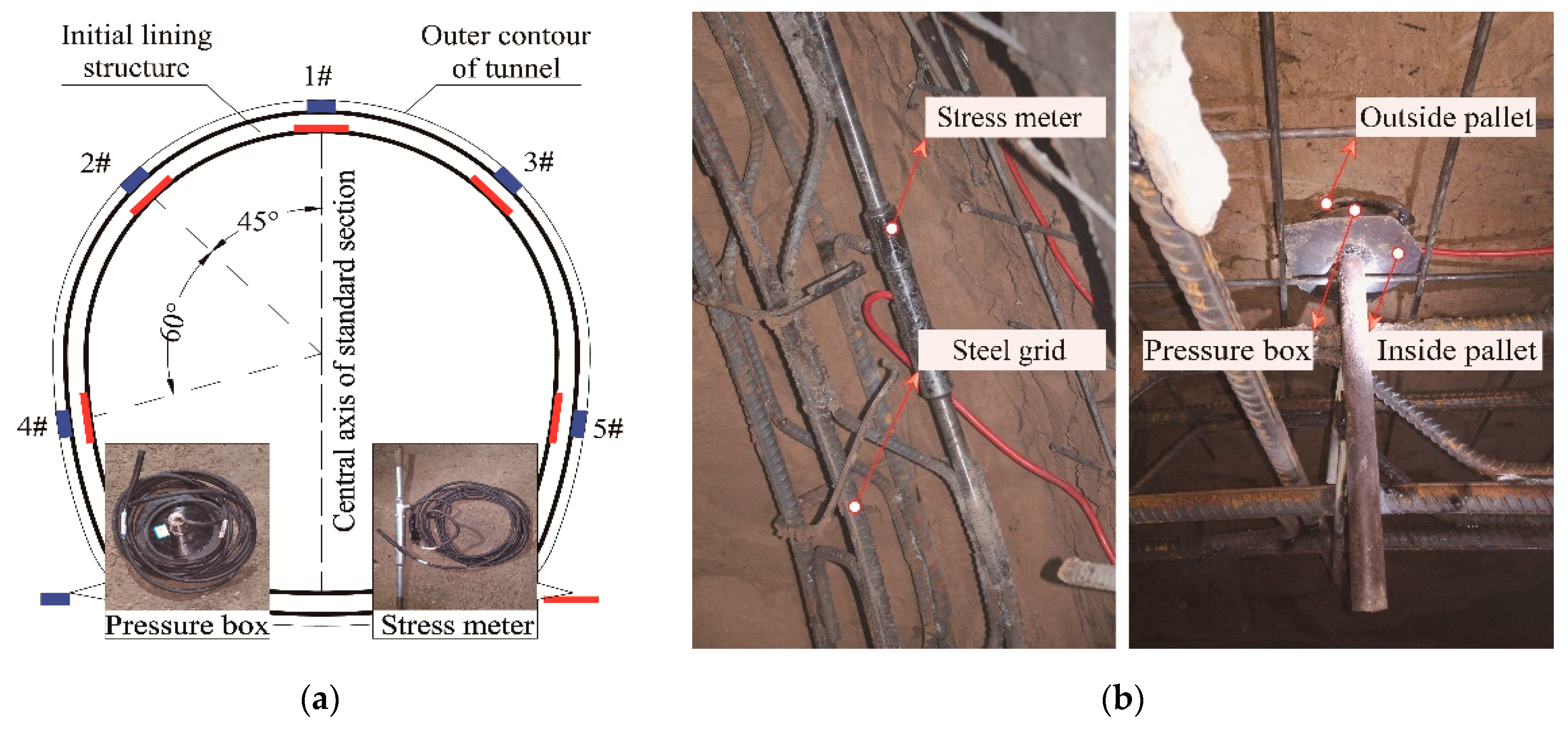
To clarify the difference in mechanical properties in silty clay strata under different water contents and optimize the support scheme, silty clay is subdivided according to gradation and liquid index, combined with laboratory test and geological survey data [35,36,37]. The classification criteria are shown in Table 1. On this basis, the stress release and displacement law of the surrounding rock in the silty clay stratum during excavation are further clarified based on a field test, and the stress law of the initial lining structure is obtained. In the construction section, some standard sections are selected to carry out field tests and monitor the settlement of the vault roof in the process of tunnel excavation and support. In addition, the earth pressure box and the steel bar axis stress meter are embedded to monitor the pressure between the initial lining structure and the surrounding rock and the internal force of the steel grid, respectively. To ensure the accuracy of the monitoring data, rigid pallets are installed on both sides of the pressure box to make it fit the surrounding rock closely and eliminate the influence of stiffness differences between different media. The stress meter is connected at the design position of the steel grid by overlap welding. Once the instruments were installed, the initial measured values were collected immediately. The installation of the instrument and the actual effect are shown in Figure 2a,b.

3. Determination of the Key Curves of CCM

3.1. Ground Reaction Curve

The convergence-confinement method is used to analyse the safety and stability of the surrounding rock and supporting structure during tunnel excavation and support. In actual construction, the rheological characteristics of the surrounding rock are not considered. The supporting structure is assumed to be homogeneous linear elastic body, and the soil is assumed to be an ideal elastoplastic material satisfying the Mohr-Coulomb yield criterion. The process of tunnel excavation and support is simulated based on the plane strain model [38]. The self-weight of the computing medium is neglected. The restraint effect of the tunnel face and surrounding rock during the excavation is analysed by the virtual support force [39] acting on the model.
In actual engineering, the tunnel section is generally a multicentered circular section, which is equivalently solved by a virtual circle with equal area [40]. The shape influence coefficient k is introduced to correct the virtual circle´s radius. The corrected virtual circle´s radius rl is defined as the “equivalent radius”, which can be expressed as follows:
r l = k × ( S / π ) 1 2
where k is the correction coefficient of the section shape. The correction coefficient of arch cavern is taken as 1.1. S is the excavation area of the tunnel section.
Using the virtual supporting force method [39], the initial displacement of stratum before excavation can be expressed as:
U 0 = ( 1 + μ s ) ( 1 - 2 μ s ) r l P 0 E s
Assuming that the surrounding rock has reached the plastic state through stress redistribution and the plastic equilibrium state has been obtained, the radius of the plastic zone can be expressed as:
r p = r l [ 2 P 0 2 σ c / ( 1 ξ ) ( P i + σ c / ( ξ 1 ) ) ( ξ + 1 ) ] 1 ξ 1
The displacement of the surrounding rock within the plastic circle can be expressed as [41]:
U P = 1 + μ s E s [ P 0 + σ c ξ 1 ( σ c ξ 1 + P i ) ( r p r l ) ξ 1 ] r p 2 r l
The displacement of the surrounding rock in the elastic zone can be expressed as [41]:
U e = 1 + μ s E s P 0 [ ( 1 2 μ s ) r + r p 2 r l ] 1 + μ s E s σ R 0 r p 2 r l
where P0 is the original in-situ stress. Pi is the virtual supporting force produced by the restraint effect of the tunnel face and surrounding rock. Es, cs, φs, and μs represent Young’s modulus, cohesion, internal friction angle and Poisson’s ratio of the surrounding rock, respectively. σR0 is the stress in the outer boundary of the plastic circle, and r is the distance from the surrounding rock to the tunnel axis. σ c = 2 c s cos φ s / 1 sin φ s , ξ = ( 1 + sin φ s ) / ( 1 sin φ s ) . Then, the convergence displacement of the surrounding rock after excavation can be expressed as:
U = U e + U P U 0
In the elastoplastic analysis of the surrounding rock stress distribution, the virtual supporting force Pi imposed on the excavation boundary is a function of the surrounding rock stress release ratio with respect to time. According to previous research [42,43], the variation in the stress release of the surrounding rock in tunnel excavation with time can be expressed as:
β = 1 0.7 e 3.15 v 2 r l t
Then, the stress of the unreleased part bearing by the surrounding rock itself can be expressed as:
P i = P 0 ( 1 β ) = 0.7 e 3.15 v 2 r l t P 0
where P0 is the original in-situ stress. T is the excavation time and takes the moment of excavation of the tunnel face as the time zero point. V is the average advance speed of tunnel face, and rl is the equivalent radius of the tunnel.
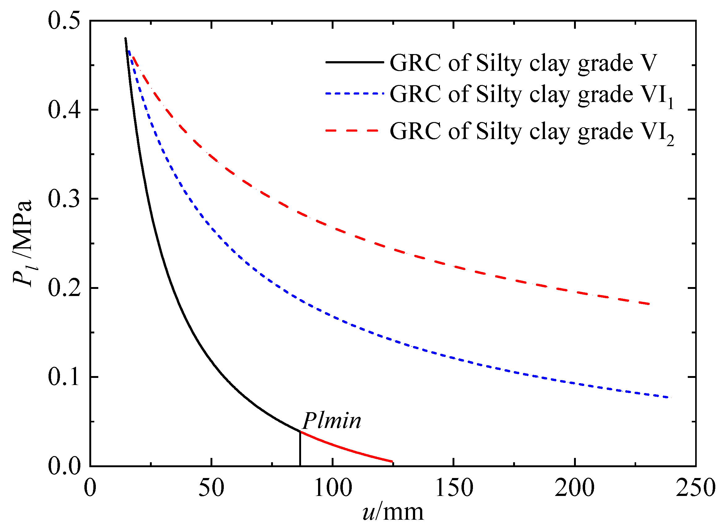
As the tunnel face advanced, the restraint effect of the tunnel face on the surrounding rock decreased. This means that the virtual support force Pi keeps decreasing, and the stress release rate of the surrounding rock gradually increases. When different supporting times are selected to install the initial supporting structure, different supporting loads will be obtained. Then, the supporting load Pl is used to replace the virtual supporting force. The relationship between the supporting load Pl and the displacement of the tunnel can be obtained by simultaneously solving Equations (6) and (8) using the parameters from Table 1, which means the ground reaction curve (GRC) of the surrounding rock (Figure 3).
It should be noted that the rock mass in the loosening zone will collapse by gravity if the supporting structure is set too late. To determine the minimum supporting force Plmin provided by the supporting structure and the maximum radius rpmax of the permissible plastic zone, the resistance required to maintain the balance of the slip body in loosening zone is taken as the minimum support resistance in the limit equilibrium state. The soil cohesion is taken as 70% of the original parameter when calculating the maximum radius of the plastic circle [44]:
P l min = γ s r l ( r pmax r l 1 ) 2
r pmax = r l [ ( P 0 + c s cot φ s ) ( 1 sin φ s ) ( P l min + c s cot φ s ) ( 1 + sin φ s ) ] 1 sin φ s 2 sin φ s
According to Equations (9) and (10), the maximum radius of the safe plastic circle and the minimum support pressure provided by the supporting structure can be determined using the Newton iteration method (Figure 3). At the same time, the selection of the supporting time should not only ensure that the support resistance is greater than the minimum support force, but also ensure that the displacement of the surrounding rock meets the requirements of the industry standard [45].

3.2. Longitudinal Displacement Profile

Previous research [46] has shown that the longitudinal displacement profile (LDP) of tunnels presents the trend of a hyperbolic tangent function. It is assumed that the relationship between the longitudinal displacement value and the advancing distance of the tunnel face during tunnel excavation satisfies the following equation:
S ( t ) = S 0 2 [ tan h a 1 ( x b 1 ) D + 1 ]
where S(t) is the longitudinal displacement value at different times during tunnel excavation (m). x is the tunnel face advancing distance (m). D is the tunnel diameter (m). S0 is the final displacement of the tunnel (m). a1 and b1 are fitting parameters.
According to Equations (6) and (8), the law of surrounding rock convergence with time after tunnel excavation can be easily obtained. Combined with the advancing speed of the tunnel face in practical engineering, Equation (11) is used as a custom function in MATLAB’s Curve Fitting Toolbox to fit the actual longitudinal displacement profile (LDP) during tunnel excavation in silty clay stratum under different subgrade conditions. The fitting parameters are shown in Table 2.
When the initial lining structure is applied, the surrounding rock further releases stress under coordinated action with the lining structure. With the passage of time, the rate of stress release decreases and finally tends to a stable value, which is related to the parameters of the surrounding rock, the time of lining construction, and the stiffness of the lining structure. In practical engineering, the monitoring points of vault settlement are laid at the same time as the initial lining structure. However, the initial data are usually collected within one to three days after the supporting structure is set up due to the limitation of operation space. The stiffness of the spray concrete support is small in the initial stage of lining construction, and the convergence displacement of the surrounding rock develops further. Therefore, it is necessary to analyse the convergence displacement law of the surrounding rock. In practical engineering, the advancing speed of the tunnel face is 3 m/d, and the setting time of the lining structure is taken as time zero t0. The vault settlement data from the field test section are regressed and analysed, which can be expressed as follows:
S 1 = S L 2 [ tan h a 2 ( 3 t 1 b 2 ) D + 1 ]
where t1 is the initial time for monitoring the vault settlement. S1 is the corresponding coordinated displacement under support. SL is the final longitudinal displacement of the surrounding rock under lining construction.
Based on the above assumptions, the field-measured vault settlement data are analysed using Curve Fitting Toolbox in MATLAB, and the fitting formula is as follows:
S L = 1 2 { S l + ( S l + S 1 ) 2 [ tan h a 2 ( 3 t 1 + b 2 ) D + 1 ] } [ tan h a 2 ( 3 t + b 2 ) D + 1 ] S 1
where SL is the fitted value of the crown settlement from the test section under support. Sl is the final value of the crown settlement measured in the test section. S1 is the settlement value of the monitoring section when the initial value is taken after supporting. t1 is the time when the settlement data are collected first from the test section. t is the advancing time of the tunnel. In addition, a2 and b2 are the fitting parameters. The field-measured data are fitted and shown in Table 3.
Table 3 shows that the law of convergence displacement of the surrounding rock under lining construction can be expressed as:
S ( t ) = S L 2 [ tan h 0.1658 ( 3 t 5.931 ) D + 1 ]
where SL is the final total value (m) of the vault displacement under lining construction. The average value (1.5383 × 10⁻² m) is adopted in the calculation.
It is easy to know from Equation (14) that the rate of vault displacement is the largest when the tunnel face is pushed approximately 5.931 m after the supporting structure is completed. The reason is that when the tunnel face is moved approximately one time ahead of the tunnel diameter, the restraint effect of the tunnel face on the surrounding rock basically disappears, and the stiffness of the supporting structure has not yet met the design requirements. At the same time, the gap between the initial lining structure and surrounding rock has not been fully filled.
Under the combined support of the steel grid and spray concrete, the stiffness of the supporting structure increases with time, which means that the rate of stress release of the surrounding rock gradually decreases and eventually tends to a stable value. According to the field monitoring data (Table 4), the stress release ratio of the surrounding rock is between 78% and 90% after the coordinated displacement between the surrounding rock and supporting structure tends to be stable. The average value of the field measured data is taken in the calculation process, which means that the stress release ratio of the surrounding rock in the silty clay stratum is 85% under the above working and supporting conditions. According to the actual situation on site, the supporting structure was applied within 0.2~0.5 d after excavation. The stress release of the surrounding rock will occur due to the displacement. Therefore, there is a relationship between the convergence displacement of surrounding rock (including the preexcavation displacement ui, the presupporting displacement u1 and the displacement SL under support construction) and the stress release ratio β, which can be expressed by the fitting formula as:
β = 1.12 0.01798 u i + u 1 + S ( t )
where u1 is the convergence displacement when the supporting structure has not yet played its role, which can be determined by Equation (11).
Combined with Equations (14) and (15), the stress release ratio of the surrounding rock under supporting construction can be expressed as:
β = β max ( β max β t 0 ) e 0.3 t
where βmax is the maximum stress release ratio of the surrounding rock. βt0 is the stress release ratio when the supporting structure starts to play its supporting role. t is the time of the supporting structure acting.
Combined with Equations (6), (8) and (16), the longitudinal displacement profile of the tunnel under the supporting structure can be further determined (Figure 4).
Figure 4 shows that the longitudinal displacement profile of the surrounding rock during the whole period of tunnel excavation can be determined based on the time of supporting structure construction. Because of the supporting structure, the surrounding rock is in the three-dimensional stress state. The larger the stress release ratio of the surrounding rock is, the larger the convergence displacement of the tunnel is. Therefore, the optimum supporting time has a significant impact on the safety and economy of tunnel construction. The comparison of vault settlement obtained by theoretical calculation and field monitoring is made in Figure 5a,b, corresponding to certain excavation times. The initial data acquisition of the two actual monitoring sections in Figure 5a starts from the first day after support construction, while the two sections in Figure 5b start from the third day after support construction. There are obvious fluctuations in the measured data, mainly considering the influence of different support stages, especially the Advanced support on the vault settlement. The stress release of the surrounding rock reflected by vault settlement is an irreversible process, therefore the settlement should be monotonically increasing from a theoretical point of view. The trends of the measured data in Figure 5 show a good agreement with the theoretical calculation results, ignoring the data fluctuations caused by measurement errors and support effects in the measured data.

3.3. Support Characteristic Curve

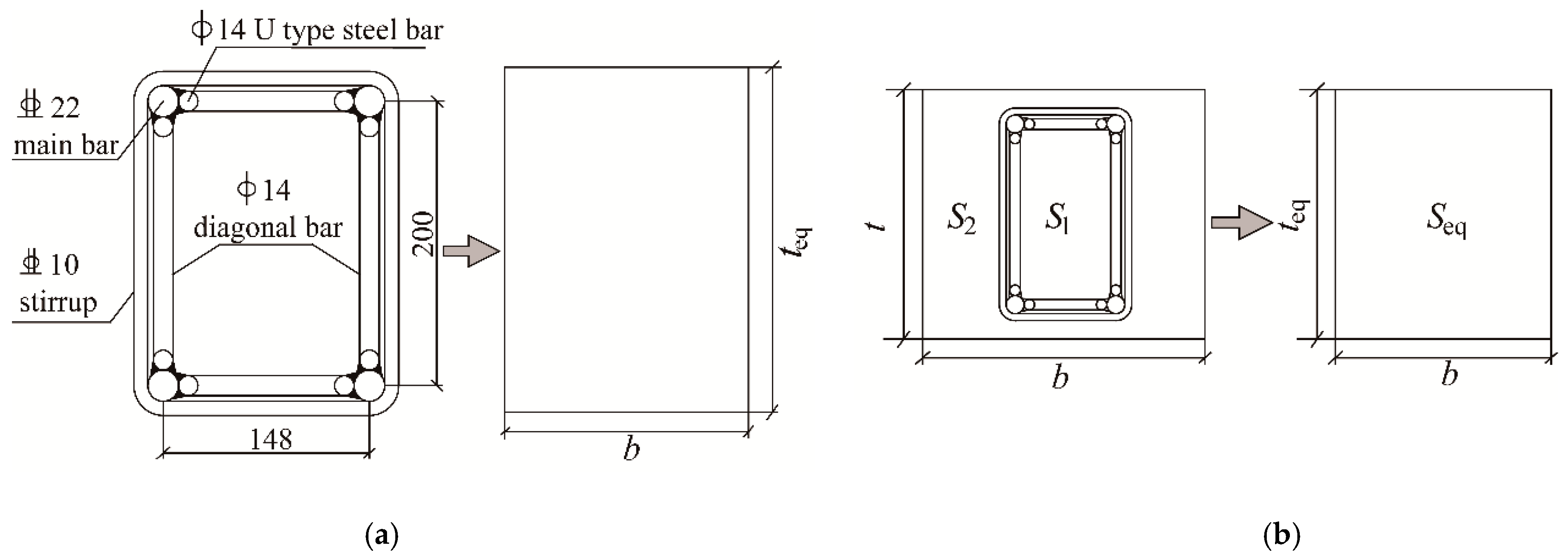
The imposition of the support structure can restrain the development of stress release and deformation of the surrounding rock, accelerating the convergence of the surrounding rock deformation. Therefore, CCM can be used to study whether the strength of the support structure meets the requirements and clarify the support time. In this project, the combined support of steel grid and spray concrete is adopted as the initial supporting structure, and different support forms are treated as support members with uniform thickness by the cross-section equivalent method [47]. The cross-section equivalent sketches are shown in Figure 6a,b.
The equivalent Young’s modulus Eeq and equivalent thickness teq of the supporting structure are calculated as:
E eq = ( D 1 + D 2 ) b t e q
t eq = 12 K 1 + K 2 D 1 + D 2
where D and K are the compressive stiffness and flexural rigidity of a single support member, respectively, which can be expressed as:
D = E A / ( 1 μ 2 )
K = E I / ( 1 μ 2 )
where E and μ are the Young’s modulus and the Poisson ratio of the supporting material, respectively. I is the moment of inertia of the supporting member. A is the section area.
According to the study of Guan [48], in a support system with thickness t, the stiffness Leq, displacement ul and maximum support force Pmax of the supporting structure can be expressed as:
L eq = E eq r l ( 1 + μ ) r l 2 ( r l t eq ) 2 ( 1 2 μ ) r l 2 + ( r l t eq ) 2
u l = P l r l L eq
where r l is the equivalent radius of the lining structure. u l is the radial deformation of the lining structure.
P max = σ s 2 [ 1 r l 2 ( r l + t eq ) 2 ]
For the steel grid supporting structure, σ s is the equivalent yield stress of the equivalent rectangular section, which can be calculated as:
σ s = σ s A s b t e q
where σ s is the yield stress of the main bar of the steel grid. As is the section area of the steel grid. b is the spacing of the steel grid supporting structure. For the calculation of support characteristic curve of the combined supporting structure, the calculation parameters can be replaced by the equivalent parameters of the combined support. The maximum supporting force P12max of the combined support system can be expressed as:
P 12 max = min [ ( K 1 + K 2 ) P 1 max K 1 , ( K 1 + K 2 ) P 2 max K 2 ]
The supporting structure in this project is designed as a combination of a steel grid and spray concrete. It is considered that the surrounding rock is mainly supported by the steel grid in the earlier stage of support construction during the calculation and analysis of the support characteristic curve. Then, the spray concrete and the steel grid play a role together in the later stage [6]. According to the supporting parameters (Table 5), the supporting effect of a single support with a steel grid and a combined support with a steel grid and spray concrete can be calculated separately (Table 6). The calculation formula of the support characteristic curves can be expressed as follows:
(a)
Steel grille acts as support alone:
u l 1 = P l 1 r l L l 1
(b)
Steel grid and spray concrete are combined to support:
u l 12 = u l 1 max + ( P l 12 P l 1 max ) r l L l 12
According to previous research [47], the axial stress of the steel grid in the combined support system can be expressed as follows:
σ = 2 P l r l D 1 A s ( D 1 + D 2 )
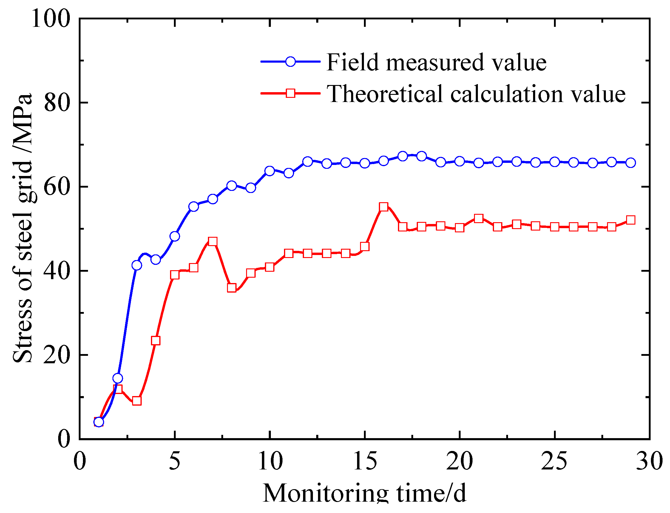
The average value of the measured supporting force from the test section ④ was adopted to calculate the axial stress of the steel grid using Equation (28). The calculation results are compared with the measured axial stress of the steel grid (Figure 7). It can be seen from Figure 7 that the axial stress of the steel grid tends to be stable approximately 15 days after support construction, which is basically consistent with the calculated value. However, the calculated value of the grid axial stress is slightly less than the measured value. The theoretical calculation results were the support structure axial force back-calculated using the surrounding pressure. The equivalent treatment of the loads and the equivalent treatment on the support structure geometry were carried out in the calculation process. Therefore, it is reasonable that the calculated value is less than the measured results. The average difference between the calculation results and the measured results is only 28%, so the guiding significance of the computational model in engineering is obvious.
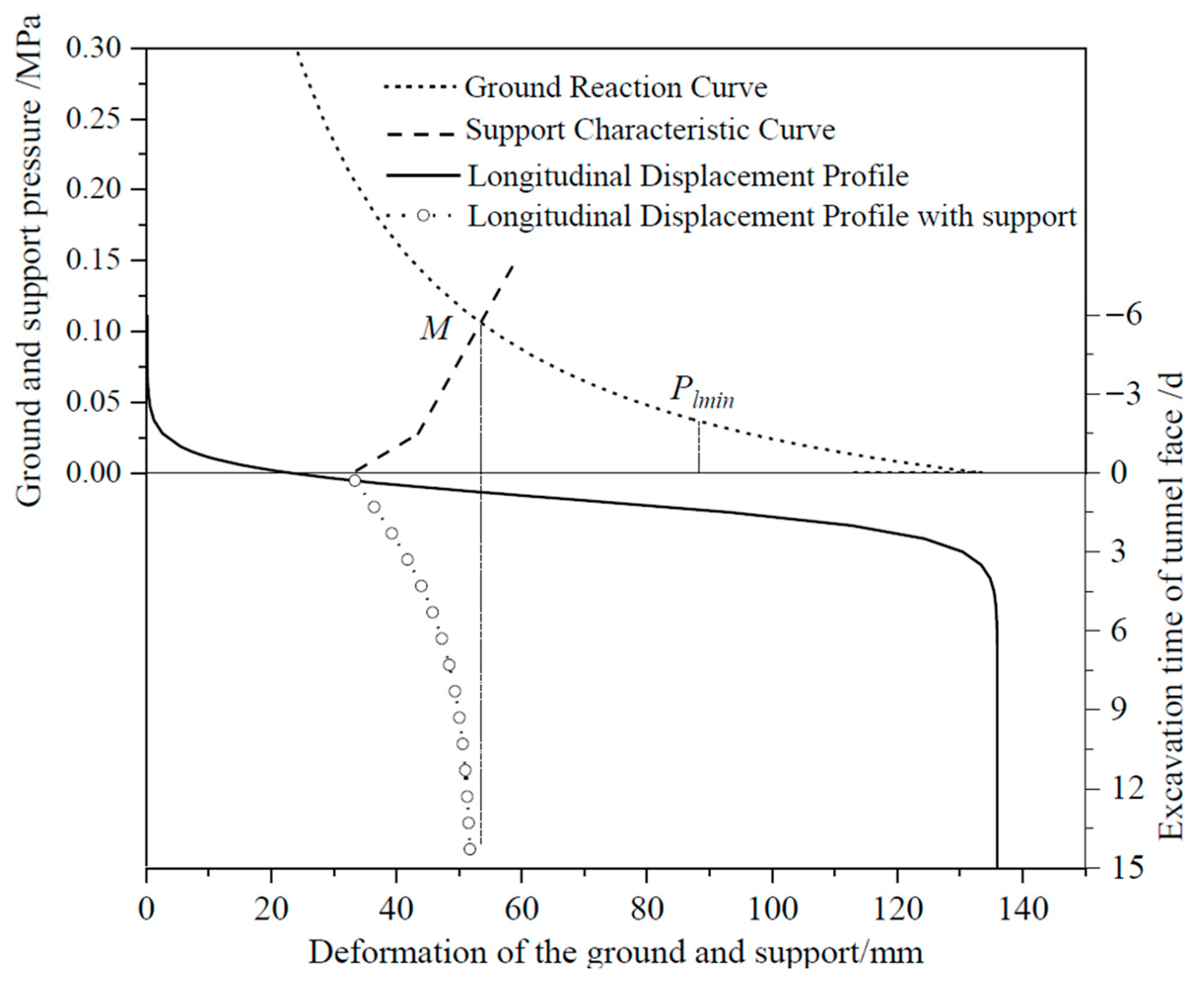
As a useful and effective analytical method, CCM has the advantage of analysing the mechanical behavior of the surrounding rock and the ground–support interactions during tunneling in a comprehensive manner [49]. Figure 8 shows the graphic interpretation of the CCM for subgrade V in silty clay stratum according to the analysis above. For the silty clay of subgrade V, the support scheme and structure adopted can effectively restrain the deformation of the surrounding rock. Under the action of the support structure, the deformation of the surrounding rock can converge more quickly, and the overall deformation of the support structure is approximately 18.45 mm, which is less than the permitted deformation of the support structure, 25.63 mm (Table 6). In addition, the surrounding rock pressure borne by the support structure is approximately 0.1 MPa, which is far less than the maximum bearing capacity of the supporting structure, 1.897 MPa (Table 6). It should be noted that the initial support construction is generally completed in time to ensure the stability of the surrounding rock after tunnel face excavation in soil tunnels. However, it can be seen that the support scheme currently adopted for subgrade V in silty clay stratum has a large safety space. From the perspective of economic cost, when intersection point M of the GRC and SCC is closer to point Plmin, the cost of artificial supports, including the cost of materials and installation, will be significantly reduced. Therefore, it is necessary to quantitatively assess the safety of the surrounding rock and further analyse the stability of subgrades VI1 and VI2 under current construction conditions.

4. Support Scheme Design

4.1. Safety Factor of the Permitted Displacement

The safety factor of the surrounding rock deformation during construction is analysed, and then the optimization of the supporting time is analysed according to the surrounding rock stress release. The deformation and stress release ratio of the surrounding rock must not be too large before the initial support really works. The initial supporting structure is required to bear all the loads during the construction stage. The secondary lining structure is used as a safety reserve for additional loads, which are caused by initial support degradation, formation creep, earthquakes, and so on. Moreover, the application of the supporting structure must be able to effectively control the deterioration of the surrounding rock displacement so that the displacement of the surrounding rock is within a reasonable range. The permitted displacement safety factor of the surrounding rock under the supporting structure acting is defined as [50]:
F s = u max u in u eq u in
where Fs is the safety factor of the permitted displacement. umax is the cumulative maximum permitted displacement of the surrounding rock. uin is the previous displacement of the surrounding rock before support construction. ueq is the total displacement of the surrounding rock, which finally tends to be stable under the action of the supporting structure. The safety factor of the permitted displacement must be greater than 1.5 to ensure the safety of tunnel construction.
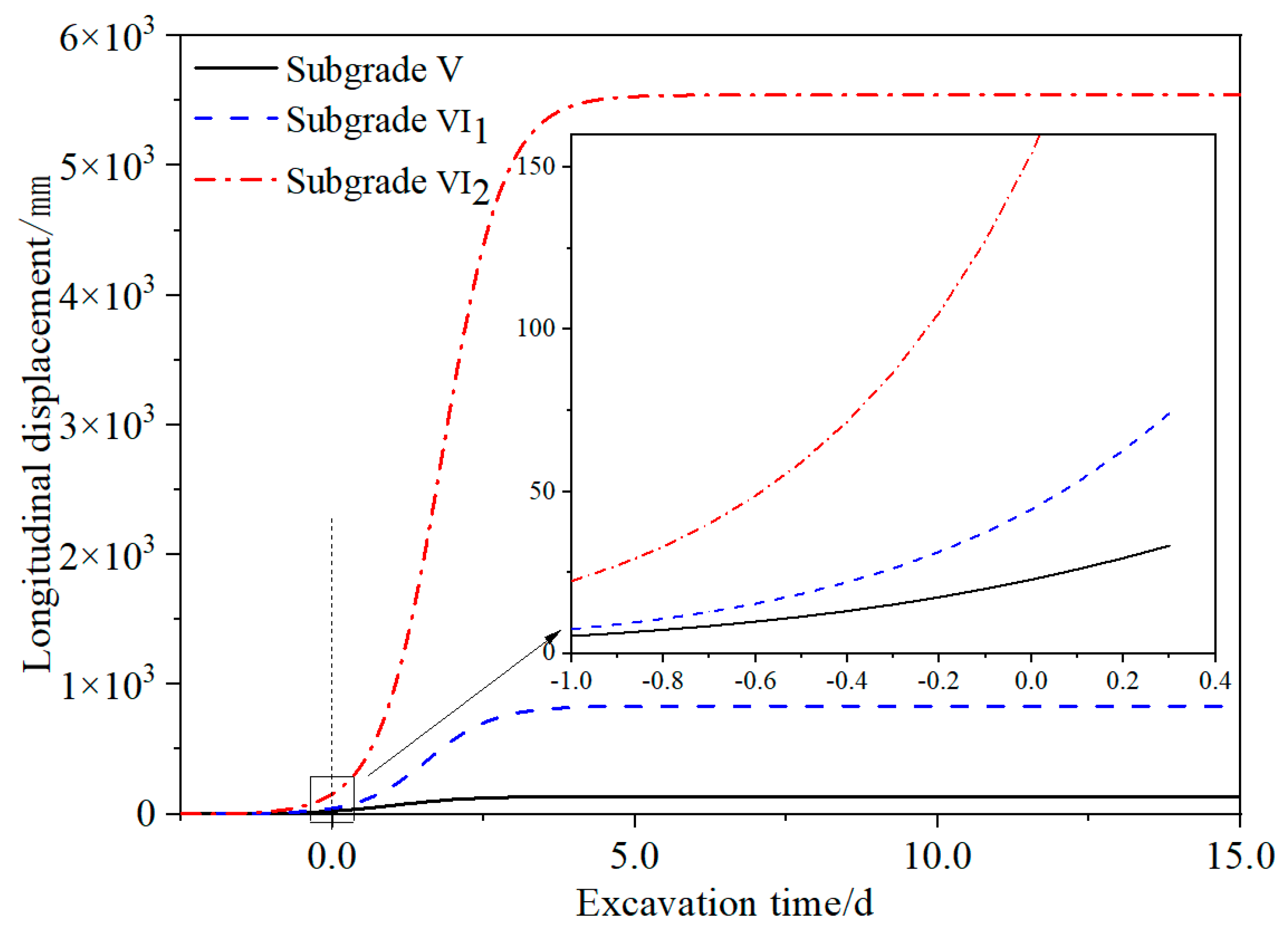
The convergence displacement of the tunnel during the excavation process without support in the silty clay stratum under different subgrade in the silty clay stratum is shown in Figure 9. The safety factor of permitted displacement under the above excavation, and the support scheme is further calculated and analysed (Table 7).
Table 7 shows that the safety factor of permitted displacement can reach 2.91 in the construction of grade V surrounding rock in silty clay stratum under the current excavation and support scheme, which means that there is sufficient self-stabilizing capacity for the surrounding rock to ensure the construction of the initial support. However, the safety factor of permitted displacement is 1.40 in the construction of the surrounding rock of subgrade VI1 in silty clay stratum. This means that the surrounding rock in this kind of stratum does not have enough self-stabilizing capacity to guarantee the initial support construction. Under the premise that the supporting stiffness meets the requirements (Table 6), it is suggested to adopt auxiliary construction methods such as advanced small conduit support to ensure construction safety and quality. For the surrounding rock of subgrade VI2 in the silty clay stratum, the surrounding rock has produced convergent displacement exceeding the normal value [45] before the tunnel face excavation. Therefore, it is necessary to reinforce the surrounding rock before excavation, and deep hole grouting reinforcement or the auxiliary construction of advanced pipe shed can be considered. In addition to reinforcing the strata to improve the self-stabilizing capacity of the surrounding rock, advanced support can also transfer the ground pressure in front of the tunnel face to the initial support structure (e.g., advanced small conduit, advanced pipe shed). Advanced support can not only restrain the surrounding rock deformation, but also further improve the utilization rate of the initial support [35]. In this way, it can effectively restrain the excessive deformation of the surrounding rock and help the self-stabilization of the surrounding rock in the early stage of tunnel face excavation, while gaining time for the initial support construction. However, the selection of specific advanced support schemes and timing needs further study.

4.2. Optimization of Supporting Time

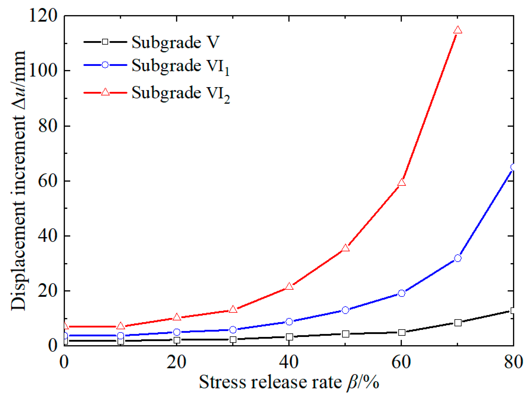
Once the safety factor of the permitted displacement is clarified, auxiliary support solutions for different subgrade strata need to be further defined when the self-stabilizing capacity of the surrounding rock cannot meet the construction requirements. The surrounding rock displacement under different subgrades in the process of stress release is studied to further clarify the safety requirements of the initial support in silty clay strata, and the optimal time of initial support can be determined. Taking a point at the vault as the research object, the displacement of the vault with the release of the surrounding rock load is recorded as shown in Figure 10.
It can be seen that the surrounding rock displacement varies greatly with stress release in the silty clay stratum under different subgrade conditions. The increment of surrounding rock displacement increases as the stress release ratio increases during tunnel excavation under different subgrade conditions. Under the current excavation and supporting conditions, the silty clay surrounding rock of grade V has good lithology. When the stress release ratio is less than 60%, the displacement of the surrounding rock should increase linearly. When the subgrade of the surrounding rock is subgrade VI1, the displacement should increase linearly before the stress release ratio is less than 30%, and then the displacement increases sharply. For the surrounding rock of subgrade VI2 in the silty clay stratum, it is noteworthy that the displacement increases sharply after the load release ratio exceeds 10%. The critical load release ratio βs of the surrounding rock under subgrades V, VI1, and VI2 is 60%, 30%, and 10%, respectively.
The development of the surrounding rock deformation corresponding to the change in the stress release rate is the inherent expression of the surrounding rock self-stabilizing capacity. The values of the critical stress release ratio are substituted into Equation (8), and the displacement corresponding to the proposed supporting time is 37.17 mm, 23.43 mm, and 10.39 mm under the surrounding rock conditions of subgrade V, VI1, and VI2, respectively. Then, the critical displacement values are substituted into Equation. (11), and the corresponding tunnel face propulsion distances x of the optimal supporting time are 1.03 m, −1.09 m, and −4.18 m, respectively. This means that the self-stabilization requirements of the surrounding rocks can be met within 1 m after the tunnel excavation face for the silty clay stratum of subgrade V. The self-stabilization time of the surrounding rock is 8.24 h according to the advancing speed (3 m/d) adopted in the current project. Therefore, the existing design schemes for initial support can meet the stability requirements of the surrounding rock in subgrade V. However, for the surrounding rock of subgrade VI1, the range of advancing support is approximately 1 m ahead of the tunnel face. Advanced small conduit support can be considered in practical engineering. For the surrounding rock of subgrade VI2, the range of advancing support should be approximately 4 m ahead of the tunnel face. It is suggested to adopt an advanced pipe shed or deep hole grouting reinforcement in front of the tunnel face.

5. Discussion

This study attempts to clarify the deformation evolution law of tunnel surrounding rock from the perspective of stress release. However, the concept of stress release is based on many assumptions [22,23,24,25,26], and there are difficulties in monitoring the stress release process. Therefore, it is a feasible research method to invert the stress release law by the deformation of the surrounding rock. Based on the measured data of vault settlement at the construction site, the restraining effect of the support structure on stress release is deduced, and then the stress release law and convergence displacement of the surrounding rock under the action of the support are obtained. Combined with the GRC, the LDP and the SCC, the convergence displacement of the surrounding rock under different support schemes can be predicted, and the rationality of the support scheme can be effectively evaluated. Based on the effect of the stress release ratio on the deformation increment of the surrounding rock, the optimal timing of support can be determined effectively.
It should be noted that the method proposed in this paper relies on field measurement data, and the validity and completeness of the measured data have a large impact on the analysis results. Fortunately, the role played by monitoring and measurement in the tunnel construction process is increasing and gradually developing towards intelligence. This means more efficient access to monitoring data in engineering, a larger volume of data, and more monitoring data will be available to participate in the analysis process. The focus on monitoring and measurement will have a good promotion effect on the development and application of this method and will further promote the sustainable development of monitoring and measurement technology in tunnel construction.

6. Conclusions

Based on the phase III project of Harbin Metro Line #1, the convergence–confinement method is used to analyse the safety of tunnels during excavation and support under different subgrade surrounding rock conditions in silty clay strata. The major results obtained are as follows:
(1)
The stress release ratio of the surrounding rock in the silty clay stratum is approximately 78–90% when the supporting structure and surrounding rock displacement are coordinated and stable under the current excavation and support conditions. The surrounding rock displacement began at one time diameter of the tunnel in front of the tunnel face. Under the condition of subgrade V in the silty clay stratum, the displacement before installing the supporting structure is approximately 33.28 mm, which belongs to the nonmonitorable portion, accounting for 64% of the total displacement of the surrounding rock. After installation of the supporting structure, the coordinated displacement is approximately 18.45 mm, which belongs to the monitorable portion, accounting for 36% of the total displacement.
(2)
Based on the convergence–confinement method, the longitudinal displacement law of silty clay under different subgrade conditions is determined by the hyperbolic tangent function. Then, the stress release law and displacement law of the surrounding rock under support are further determined. In the existing supporting design, the permitted displacement is 16.31 mm, and the maximum supporting force is 0.221 MPa when the steel grid support alone. The permitted displacement is 25.63 mm, and the maximum supporting force is 1.897 MPa for the combined support of the steel grid and spray concrete.
(3)
For the condition of subgrade V in a silty clay stratum, the safety factor of the permitted displacement is approximately 2.91, which can ensure tunneling stability. It is suggested that initial support should be carried out within 1 m after face advancement. For the surrounding rock of subgrade VI1, the safety factor of the permitted displacement is 1.40. The initial support must be carried out 1 m ahead of the tunnel face. Therefore, it is suggested to adopt advanced small conduits to ensure the safety and quality of construction. For the condition of subgrade VI2, the surrounding rock must be supported 4 m ahead of the tunnel face, and the advanced pipe shed or deep hole grouting reinforcement can be considered. The treatment effect of the relevant schemes still needs to be further studied.

Author Contributions

Conceptualization, K.L. and W.Z.; methodology, K.L.; software, W.Z.; validation, K.L., W.Z. and J.L.; formal analysis, J.L.; investigation, J.L.; resources, K.L.; data curation, W.D.; writing—original draft preparation, K.L.; writing—review and editing, W.Z. and J.L.; visualization, J.L.; supervision, W.Z.; project administration, W.D. All authors have read and agreed to the published version of the manuscript.

Funding

This research was funded by the Fundamental Research Funds for the Central Universities, grant number N2201017, and the Natural Science Foundation of Shandong Province, grant number ZR2021ME135.

Institutional Review Board Statement

Not applicable.

Informed Consent Statement

Not applicable.

Data Availability Statement

The data provided in this study could be released upon reasonable request.

Conflicts of Interest

The authors declare no conflict of interest.

References

  1. Su, Y.H.; Xiao, F. Research on quantification optimization of tunnel self-stability based on catastrophe theory. Highw. Eng. 2020, 45, 63–67. [Google Scholar] [CrossRef]
  2. Li, S.C.; Yan, Q.; Xie, C.; Wu, J. The mechanical behavior of composite supports of steel-grid in loess tunnel. Chin. J. Rock Mech. Eng. 2017, 36, 446–456. [Google Scholar]
  3. Zhang, Z.; Xu, T.; Cao, G.; Liu, X. Distribution Features of the Minimum Rock Cover Thickness of the Surrounding Rock Self-Stability of the Metro Tunnel in the Soil-Rock Dualistic Stratum. Adv. Civ. Eng. 2020, 2020, 8840043. [Google Scholar] [CrossRef]
  4. Tanoli, A.Y.; Yan, B.; Xiong, Y.-L.; Ye, G.-L.; Khalid, U.; Xu, Z.-H. Numerical analysis on zone-divided deep excavation in soft clays using a new small strain elasto–plastic constitutive model. Undergr. Space 2021, 7, 19–36. [Google Scholar] [CrossRef]
  5. Kang, Y.; Liu, Q.; Xi, H.; Gong, G. Improved compound support system for coal mine tunnels in densely faulted zones: A case study of China’s Huainan coal field. Eng. Geol. 2018, 240, 10–20. [Google Scholar] [CrossRef]
  6. Li, W.; Yang, N.; Yang, B.; Ma, H.; Li, T.; Wang, Q.; Wang, G.; Du, Y.; Zhao, M. An improved numerical simulation approach for arch-bolt supported tunnels with large deformation. Tunn. Undergr. Space Technol. 2018, 77, 1–12. [Google Scholar] [CrossRef]
  7. Wang, C.; Li, G.; Gao, A.; Shi, F.; Lu, Z.; Lu, H. Optimal pre-conditioning and support designs of floor heave in deep roadways. Geomech. Eng. 2018, 4, 429–437. [Google Scholar]
  8. Iasiello, C.; Torralbo, J.C.G.; Fernández, C.T. Large deformations in deep tunnels excavated in weak rocks: Study on Y-Basque high-speed railway tunnels in northern Spain. Undergr. Space 2021, 6, 636–649. [Google Scholar] [CrossRef]
  9. Carranza-Torres, C.; Engen, M. The support characteristic curve for blocked steel sets in the convergence-confinement method of tunnel support design. Tunn. Undergr. Space Technol. 2017, 69, 233–244. [Google Scholar] [CrossRef]
  10. Fenner, R. Untersuchungen zur Erkenntnis des Gebirgsdruckes, Gluckauf, Study of Ground Pressures. Tech. Transl. 1938, 515, 691–696. [Google Scholar]
  11. Pacher, F. Deformationsmessungen im Versuchsstollen als Mittel zur Erforschung des Gebirgsverhaltens und zur Bemessung des Ausbaues, Grundfragen auf dem Gebiete der Geomechanik/Principles in the Field of Geomechanics. In Proceedings of the 14th Symposium of the Austrian Regional Group of the International Society for Rock Mechanics, Ottawa, ON, Canada, 24–25 September 1964; Springer: Berlin, Heidelberg, 1964. [Google Scholar] [CrossRef]
  12. Ladanyi, B. Use of the Long-Term Strength Concept in the Determination of Ground Pressure on Tunnel Linings. In Proceedings of the Third Congress of the International Society for Rock Mechanics on Advances in Rock Mechanics, Washington, DC, USA, 1–7 September 1974. [Google Scholar]
  13. Eisenstein, Z.; Branco, P. Convergence—Confinement method in shallow tunnels. Tunn. Undergr. Space Technol. 1991, 6, 343–346. [Google Scholar] [CrossRef]
  14. Bukaçi, E.; Korini, T.; Periku, E.; Allkja, S.; Sheperi, P.; Sharra, L.; Barko, O. Factor of safety and probability of failure using convergence-confinement method for tunnels in rock. In Proceedings of the Geo-Environment and Construction European Conference in Geo-Environment and Construction, Tirana, Albania, 26–28 November 2015. [Google Scholar]
  15. Basirat, R.; Hassani, R.; Mahmoodian, N. Forepoling Design in Weak Medium based on the Convergence-Confinement Method. In Proceedings of the International Conference on Civil Engineering, Singapore, 1–3 May 2016. [Google Scholar] [CrossRef]
  16. Sadeghiyan, R.; Hashemi, M.; Moloudi, E. Determination of longitudinal convergence profile considering effect of soil strength parameters. Int. J. Rock Mech. Min. Sci. 2016, 82, 10–21. [Google Scholar] [CrossRef]
  17. Brown, E.T.; Bray, J.W.; Ladanyi, B.; Hoek, E. Ground Response Curves for Rock Tunnels. J. Geotech. Eng. 1983, 109, 15–39. [Google Scholar] [CrossRef]
  18. Carranza-Torres, C.; Fairhurst, C. Application of the Convergence-Confinement method of tunnel design to rock masses that satisfy the Hoek-Brown failure criterion. Tunn. Undergr. Space Technol. 2000, 15, 187–213. [Google Scholar] [CrossRef]
  19. Daemen, J.J.K. Tunnel Support Loading Caused by Rock Failure; Research Report No. MRD-3-75; University of Minnesota: Minneapolis, MN, USA, 1975. [Google Scholar]
  20. Lee, Y.-J. Determination of tunnel support pressure under the pile tip using upper and lower bounds with a superimposed approach. Géoméch. Eng. 2016, 11, 587–605. [Google Scholar] [CrossRef]
  21. Dias, D. Convergence-confinement approach for designing tunnel face reinforcement by horizontal bolting. Tunn. Undergr. Space Technol. 2011, 26, 517–523. [Google Scholar] [CrossRef]
  22. Vu, M.N.; Broere, W.; Bosch, J.W. Structural Analysis for Shallow Tunnels in Soft Soils. Int. J. Géoméch. 2017, 17, 04017038. [Google Scholar] [CrossRef]
  23. Cui, L.; Zheng, J.-J.; Zhang, R.-J.; Lai, H.-J. A numerical procedure for the fictitious support pressure in the application of the convergence–confinement method for circular tunnel design. Int. J. Rock Mech. Min. Sci. 2015, 78, 336–349. [Google Scholar] [CrossRef]
  24. Mousivand, M.; Maleki, M.; Nekooei, M.; Mansoori, M.R. Application of Convergence–Confinement Method in Analysis of Shallow Non-circular Tunnels. Geotech. Geol. Eng. 2017, 35, 1185–1198. [Google Scholar] [CrossRef]
  25. Mousivand, M.; Maleki, M. Constitutive Models and Determining Methods Effects on Application of Convergence–Confinement Method in Underground Excavation. Geotech. Geol. Eng. 2017, 36, 1707–1722. [Google Scholar] [CrossRef]
  26. Vlachopoulos, N.; Diederichs, M.S. Appropriate Uses and Practical Limitations of 2D Numerical Analysis of Tunnels and Tunnel Support Response. Geotech. Geol. Eng. 2014, 32, 469–488. [Google Scholar] [CrossRef]
  27. Bin, L.; Taiyue, Q.; Wang, Z.; Longwei, Y. Back analysis of grouted rock bolt pullout strength parameters from field tests. Tunn. Undergr. Space Technol. 2012, 28, 345–349. [Google Scholar] [CrossRef]
  28. Liu, F.; Yao, S.; Zhang, J.; Wang, Y.-Q. Field measurements of aerodynamic pressures in high-speed railway tunnels. Tunn. Undergr. Space Technol. 2018, 72, 97–106. [Google Scholar] [CrossRef]
  29. Miranda, T.; Dias, D.; Pinheiro, M.; Eclaircy-Caudron, S. Methodology for real-time adaptation of tunnels support using the observational method. Géoméch. Eng. 2015, 8, 153–171. [Google Scholar] [CrossRef]
  30. Yang, S.-R.; Huang, W.-H. Permanent Deformation and Critical Stress of Cohesive Soil under Repeated Loading. Transp. Res. Rec. J. Transp. Res. Board 2007, 2016, 23–30. [Google Scholar] [CrossRef]
  31. Ma, K.; Zhang, J.; Xu, J.; Chen, X.; Ren, Z.; Feng, J. The influence mechanism of water content on the tunnel stability in the silty clay layer. Chin. J. Rock Mech. Eng. 2022, 43, 1–12. [Google Scholar]
  32. Estabragh, A.; Parsaei, B.; Javadi, A. Laboratory investigation of the effect of cyclic wetting and drying on the behaviour of an expansive soil. Soils Found. 2015, 55, 304–314. [Google Scholar] [CrossRef] [Green Version]
  33. Wang, D.-Y.; Tang, C.-S.; Cui, Y.-J.; Shi, B.; Li, J. Effects of wetting–drying cycles on soil strength profile of a silty clay in micro-penetrometer tests. Eng. Geol. 2016, 206, 60–70. [Google Scholar] [CrossRef]
  34. Wang, Z.; Li, W.; Li, S.; Qiu, W.; Ding, W. Development of an Optimum Forepole Spacing (OFS) determination method for tunnelling in silty clay with a case study. Tunn. Undergr. Space Technol. 2018, 74, 20–32. [Google Scholar] [CrossRef]
  35. Liu, K.; Li, S.; Ding, W.; Hou, M.; Gong, Y.; Li, H. Pre-supporting mechanism and supporting scheme design for advanced small pipes in the silty clay layer. Tunn. Undergr. Space Technol. 2020, 98, 103259. [Google Scholar] [CrossRef]
  36. Horpibulsuk, S.K.; Rachan, R.L.; Chinkulkijniwat, A.; Raksachon, Y.; Suddeepong, A. Analysis of strength development in cement-stabilized silty clay from microstructural considerations. Constr. Build. Mater. 2010, 24, 2011–2021. [Google Scholar] [CrossRef]
  37. Jia, D.; Shi, F.; Zheng, G.; Xu, S.H.; An, L. Elastic modulus of soil used in numerical simulation of deep foundation pits. Chin. J. Geotech. Eng. 2008, 30, 155–158. [Google Scholar]
  38. Zhao, Y. Study on Deformation Mechanism and Control Technology of Weak Rock Surrounding Tunnel. Ph.D. Thesis, Beijing Jiaotong University, Beijing, China, 2012. [Google Scholar]
  39. Sun, J. Study and Application on Key Technology of Tunnel Structure Design; China Communications Press Co., Ltd.: Beijing, China, 2014. [Google Scholar]
  40. Zhang, P.F. Study on Approximate Building Method of Ground Reaction Curve for Non-Circular Underground Caverns. Master’s Thesis, Hunan University, Changsha, China, 2015. [Google Scholar]
  41. Li, W.J.; Zhu, Y.Q. Tunnel Mechanics; China Machine Press: Beijing, China, 2013. [Google Scholar]
  42. Qi, M.S. Study on Rheological Properties of Soft Rock with Large Deformation and its Application in Tunnel Engineering. Ph.D. Thesis, Tongji University, Shanghai, China, 2006. [Google Scholar]
  43. Sun, J.; Wang, B.J. Finite Element Analysis of Underground Structures; Tongji University Press: Shanghai, China, 1988. [Google Scholar]
  44. Zheng, Y.R. Stability Analysis and Design Theory of Surrounding Rock of Underground Engineering; China Communications Press Co., Ltd.: Beijing, China, 2012. [Google Scholar]
  45. TB10753–2010; Standard for Constructional Quality Acceptance of High-speed Railway Tunnel Engineering. Railway Engineering Technology Standards Institute China Railway Publishing House: Beijing, China, 2010.
  46. Qiao, L.; Liu, J.; Li, S.; Wang, Z.C.; Jiang, Y.Y.; Wang, Z.H. Study of spatial effect of excavation face for underground facility and its application. Rock Soil Mech. 2014, 35, 481–487. [Google Scholar]
  47. Carranza-Torres, C.; Diederichs, M. Mechanical analysis of circular liners with particular reference to composite supports. For example, liners consisting of shotcrete and steel sets. Tunn. Undergr. Space Technol. 2009, 24, 506–532. [Google Scholar] [CrossRef]
  48. Guan, B.S. Introduction to Tunnel Mechanics; Southwest Jiaotong University Press: Chengdu, China, 1993. [Google Scholar]
  49. Su, Y.; Su, Y.; Zhao, M.; Vlachopoulos, N. Tunnel Stability Analysis in Weak Rocks Using the Convergence Confinement Method. Rock Mech. Rock Eng. 2020, 54, 559–582. [Google Scholar] [CrossRef]
  50. Hu, S.M. Research on Safety of Initial Support in Metro Regional Tunnel Based on Convergence-confinement Method. J. China Railw. Soc. 2015, 37, 117–121. [Google Scholar]
Figure 1. Response of surrounding rock during excavation in silty clay stratum under different water content: (a) self-stability of surrounding rock (w = 22%); (b) large displacement and soil block collapse in vault (w = 26%); (c) instability of tunnel face and ground surface subsidence (w = 32%).
Sustainability 15 02386 g001
Figure 2. Instructions of instruments installation: (a) arrangement sketch; (b) actual installation effect.
Sustainability 15 02386 g002
Figure 3. The Ground Reaction Curve in silty clay stratum of different subgrade.
Sustainability 15 02386 g003
Figure 4. Longitudinal displacement profile of tunnel crown (silty clay of subgrade V).
Sustainability 15 02386 g004
Figure 5. Comparison and analysis of the settlement curve of tunnel crown: (a) with field measured sections ① and ②; (b) with field measured sections ③ and ④.
Sustainability 15 02386 g005
Figure 6. Sketches of equivalent representation: (a) steel grid acts as support alone; (b) steel grid and spray concrete are combined to support.
Sustainability 15 02386 g006
Figure 7. Stress contrast diagram of steel grid.
Sustainability 15 02386 g007
Figure 8. Graphic interpretation of the CCM for subgrade V in silty clay stratum.
Sustainability 15 02386 g008
Figure 9. Longitudinal displacement profile in ilty clay stratum under different subgrade conditions.
Sustainability 15 02386 g009
Figure 10. Displacement increment and stress release ratio of surrounding rock.
Sustainability 15 02386 g010
Table 1. Parameters of Silty Clay in Different Subgrade.
ParametersVoid Ratio, eDensity, G (cm3)Water Content, w (%)Plastic Limit, wP (%)Liquid Index, ILCohesion, cs (kPa)Friction Angle, φs (°)Poisson’s Ratio, μsYoung Modulus, Es (MPa)
Subgrade
V0.6–0.71.9521–2418.5–22.40.05–0.2540200.33–0.3580
VI10.7–0.81.9024–290.25–0.7525190.35–0.3850
VI20.8–0.91.8530–340.75–120180.38–0.4330
Table 2. Fitting Parameters of Longitudinal Displacement Profile.
Subgradea1b1S0 (m)SSER2
V1.7203.0280.1361.53 × 10−60.9999
VI11.9834.7080.8320.00450.9993
VI22.1185.4485.5430.36670.9990
Table 3. Fitting Analysis of Field Measured Data.
Section NumberInitial Measurement Time, t 1 i (d) Measured Final Value, S l i (mm) a2b2 S 1 i
(mm)
S L i
(mm)
SSER2
16.5650.1701–6.7949.58116.1467.88 × 10−60.9362
16.2250.2118–9.9568.97215.1972.52 × 10−50.8353
36.3520.1781–1.0698.76215.1149.27 × 10−60.8841
36.6710.1954–2.1239.46116.1325.07 × 10−60.9377
35.5530.1613–5.4999.85415.4075.52 × 10−60.9099
16.5670.1029–6.7328.67315.2408.58 × 10−60.8952
25.5470.1519–7.2918.96514.5124.86 × 10−50.8136
26.8940.1551–7.9828.42315.3178.95 × 10−50.8566
Average value-6.2970.1658–5.9319.08615.383--
Table 4. Monitoring Value of Earth Pressure on the Test Section.
Section NumberPosition 1#Position 2#Position 3#Position 4#Position 5#Average Value
0.0350.0360.0890.0340.0740.0536
0.0630.0660.1130.1610.1080.1022
0.0440.1290.2120.0730.0760.1068
0.1080.1330.090.0940.0720.0994
0.1030.0210.050.1040.0950.0746
0.0280.0840.0650.0270.0260.046
0.0860.0660.0770.0220.0280.0558
0.0290.0620.0470.0740.0340.0492
# The unit of data in the table is MPa.
Table 5. Supporting Structure Parameters.
Steel GridSpray Concrete
Eseq/GPaAs/cm2Is/m4σs/MPatseq/mEc/GPaμctc/cmLeqc/(GPa)Pmc/MPa
1.52159.78 × 10−62.920.28200.2250.521.85
Table 6. Calculated Results of Steel Grid and Steel Grid-spray Concrete.
Support FormSupport Stiffness (GPa)Permitted Displacement (mm)Maximum Support Force (MPa)
Steel grid0.044016.310.221
Steel grid-spray concrete0.584525.631.897
Table 7. Safety factor of permitted displacement.
Subgradeumax (mm)uin (mm)ueq (mm)Fs
V8733.2851.732.91
VI1100 *74.1492.591.40
VI2100 *271.60290.05<1
* 100: Data from the existing standard [45].
Disclaimer/Publisher’s Note: The statements, opinions and data contained in all publications are solely those of the individual author(s) and contributor(s) and not of MDPI and/or the editor(s). MDPI and/or the editor(s) disclaim responsibility for any injury to people or property resulting from any ideas, methods, instructions or products referred to in the content.