Article

A Study on the Hydrothermal Synthesis of Calcium Silicate Products by Calcination of Full-Component Waste Concrete

School of Civil Engineering, Dalian University of Technology, Dalian 116024, China
*
Author to whom correspondence should be addressed.
Sustainability 2023, 15(23), 16341; https://doi.org/10.3390/su152316341
Submission received: 12 October 2023 / Revised: 3 November 2023 / Accepted: 15 November 2023 / Published: 27 November 2023
(This article belongs to the Section Green Building)

Abstract

:
In order to achieve the reuse of waste concrete, the hydrothermal synthesis of low-temperature calcined calcium silica products with an ideal admixture of fly ash and waste concrete as raw materials was investigated and various properties were studied. The findings suggest that the optimal method involves adding 10% fly ash to waste concrete to lower the temperature at which calcium carbonate decomposes. The compressive strength of the specimens generally increases with increasing calcium–silicon ratio and pressure can reach up to 43.98 MPa. Nevertheless, the duration of holding requires adjustment in line with autoclave pressure: the higher the pressure, the shorter the holding time, and vice versa for lower pressure. Most of the specimens are water-resistant with softening coefficients above 0.6 and up to 0.91. The macroscopic strength is determined by the way in which the microstructure of the hydration products forms under different conditions. The optimum design for the experimental conditions should be that the pressure, holding time and calcium–silica ratio should be 1.0 MPa, 9 h and 1.0, respectively. Due to their potential for resource conservation and environmental improvement, autoclaved silicate materials manufactured from waste concrete may be a viable alternative as a green construction material.

1. Introduction

Concrete is a highly utilized material for the construction of various civil engineering structures [1,2]. Data show that, by 2021, China will produce more than 3293 million cubic metres of concrete, more than half of the world’s annual construction production [3]. The extensive use of concrete will generate more than 1 billion tonnes of waste concrete, accounting for 30% to 40% of China’s overall waste generation [4,5]. The rapid and massive production of waste concrete will have a serious impact on the environment and natural resources. Therefore, various fields have begun to pay attention to the research on the utilisation of waste concrete. The hydrothermal synthesis method provides a good solution.
Construction waste concrete often piles up, occupies large areas of land, and contributes to harmful pollution, so it is increasingly being recycled into useful materials, such as construction fillers, recycled aggregates, and bricks [6,7,8]. The reuse of waste concrete is an effective method of reducing construction waste emissions, improving resource conservation, and mitigating environmental pollution. Additionally, it brings considerable economic benefits. Waste concrete has mainly CaO, SiO2, Al2O3, Fe2O3, MgO, and SO3 chemical components. The largest proportion is CaO, accounting for more than half of the total, followed by SiO2 [9,10], which meets the raw material requirements for hydrothermal reactions. From a sustainable development viewpoint, autoclaved silicate material preparation is a practical approach for effectively recycling waste concrete. However, some technical barriers still hinder its practical implementation. For example, the efficient use of waste concrete should be accompanied by optimizing the efficiency of resource utilization through a variety of methods, such as determining the value of the batching rate, minimizing energy loss during combustion, and designing an ideal model.
Hydrothermal synthesis is a technique that involves the formation of crystalline materials directly from aqueous solutions by controlling thermodynamic variables (temperature, pressure and components) [11]. For building materials, it is a process in which raw materials containing a chemical composition dominated by calcium oxide and silica are put into a closed, high-temperature, high-pressure environment and reacted to produce calcium silicate hydrate such as tobermorite, which is divided into three main stages [12,13]: (1) dissolution of raw materials to form a C-S-H gel; (2) formation of low-crystallinity calcium silicate hydrate by a C-S-H gel; and (3) growth of low-crystallinity calcium silicate hydrate and formation of a high crystallinity of hydrated calcium silicate.
To date, many researchers have started to study hydrothermal synthesis in depth. Bao et al. [14] demonstrated the feasibility of the hydrothermal synthesis of tobermorite whiskers and described the effects of different precursors, synthesis conditions, exogenous ions, etc. Galvankova, L et al. [15] showed that the optimal temperature and pressure were determined to be 180 °C and 1 MPa for the successful hydrothermal synthesis of tobermorite with a calcium to silicon ratio of 0.83. The optimum temperature and pressure were determined to be 180 °C and 1 MPa. results of Wang, ZP et al. [16] showed that autoclave curing increased the crystallinity of C-S-H and disrupted the gel pores more than steam curing. The autoclave curing significantly contributed to the increase in polymerization of C-S-H due to interlayer dehydration and crystallization transition. The elevated temperature promotes the formation of C-S-H with a high Ca/Si ratio, which exhibits an increased stability of the structure.
Fly ash is mainly composed of amorphous SiO2, Al2O3 and a small amount of crystalline minerals, and is the fine ash captured from the flue gas after coal combustion, which is the main solid waste discharged from coal-fired power plants [17]. Currently, fly ash is mainly used as a mineral admixture in concrete and other construction industries. Qian Jueshi et al. [18] found that the calcium-containing minerals in fly ash are mainly free calcium oxide and hard gypsum, but also contain a small amount of calcium feldspar and dicalcium silicate, etc. The presence of these minerals makes the fly ash have a high hydration activity and a certain degree of self-hardening. Ying Wang et al. [19] showed that fly ash is reactive and contributes to the development of cement strength without negatively affecting cement hydration. Baoju Liu et al. [20] showed that the setting time of cement slurry was shortened with the increase in fly ash dosage and that steam curing accelerated the hardening of the mix. Qian Jueshi et al. [18] studied the impact of fly ash on calcium-containing minerals, revealing that elevated levels of calcium-containing minerals alter the shape of fly ash particles, increase the aggregation of silicate ions, and ultimately enhance the volcanic ash activity of fly ash. It is worth investigating whether fly ash has an effect on the level of calcium oxide content after calcining waste concrete.
In this study, waste-concrete-autoclaved-silicate material was utilized as a sustainable and green reuse building material. Fly ash was employed as an additive to affect the thermal activation of the waste concrete matrix. Thermogravimetric analysis of waste concrete after calcination with different fly ash contents was carried out. Raw materials were calcined at optimum dosage, and specimens with different calcium–silica ratios, autoclave pressures and holding times were taken and cured in autoclaves, and the microcomposition and structure of the specimens were determined from the results of macro- and microscopic tests. The reaction products were analysed by several microscopic methods.

2. Materials and Methods

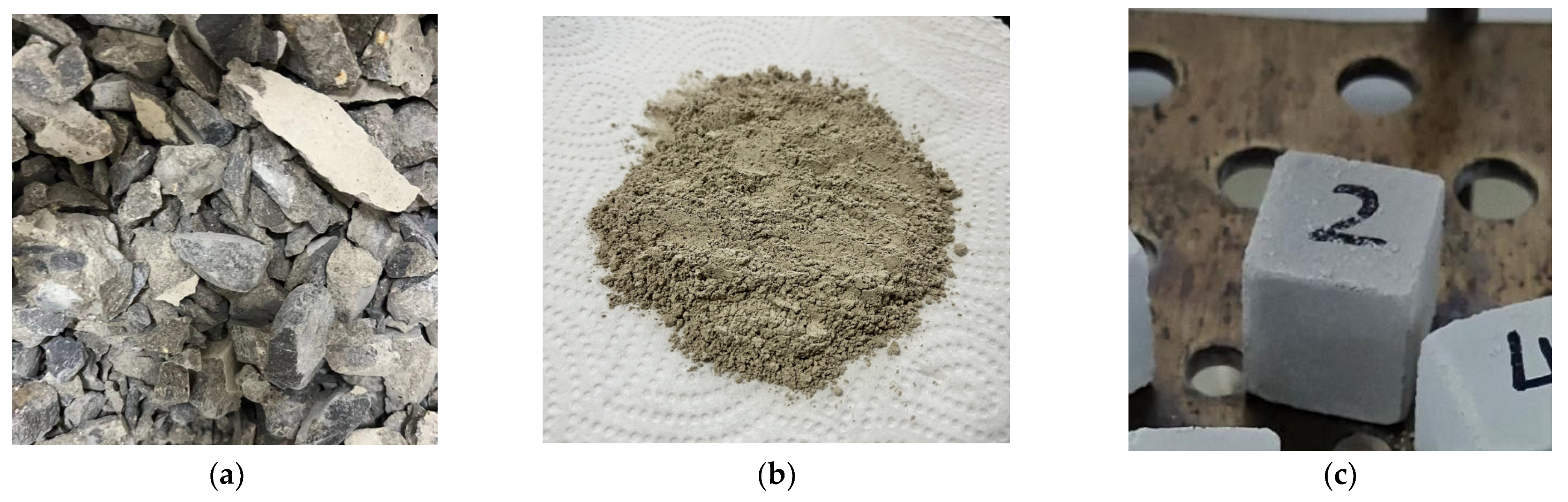
2.1. Materials and Composition

To reduce the influencing factors, in this study, four-component concrete with strength class C40 (see Table 1 for the proportions) was prepared using P.O 42.5 cement, crushed stone, river sand and tap water from Onoda Cement Plant, Dalian, China, and crushed after 28 days of standard curing in place of waste concrete. The chemical composition of the waste concrete was determined by X-ray fluorescence spectrometry (XRF-1800, Shimadzu, Kyoto, Japan), and the results are shown in Table 2.
The fly ash in this study was obtained from Gongyi No. 2 Power Plant in China, and its chemical composition is shown in Table 2, from which it can be seen that the main chemical compositions of fly ash are SiO2 and Al2O3, which can provide a small amount of silica raw material for silica–calcium products.

2.2. Materials Activation

Concrete test blocks cured for 28 d under standard conditions (temperature 20 ± 3 °C, humidity 95% or more) were crushed for the first time with a press and then put into an oven to dry for 24 h. The dried raw materials were first crushed for the second time using a heavy-duty ball mill (SYMφ500 × 500, Cangzhou, China) and finally ground using a planetary ball mill (ND-7, Nanjing, China) until the sieve residue over the 75 μm sieve was no more than 5%.
The crushed waste concrete was combined with 1%, 5%, and 10% fly ash before being placed in a muffle furnace (KSY-D-16, Longkou, China), calcined at various temperatures, kept for 30 min, and then naturally cooled to room temperature. TG and XRD analyses were utilized to choose the appropriate calcination technique and proportioning for raw material treatment.

2.3. Samples and Preparation

Twenty-seven sets of specimens were prepared from the calcined waste concrete according to the calcium–silica ratio (0.8, 0.9, 1.0), pressure vapor pressure (1.0 MPa, 1.5 MPa, 2.0 MPa) and pressure vapor holding time (3 h, 6 h, 9 h). The moulding conditions and schematic illustration of the sample preparation are shown in Table 3 and Figure 1. The specimen numbers for different calcium–silica ratios in the autoclaved regime are shown in Table 3. The calcined waste concrete was mixed with an appropriate amount of SiO2 (AR) into a dry mixture and water was added at a water–cement ratio (mass ratio) of 0.36. After stirring for 3 min, the fresh slurry was poured into stainless steel moulds (20 mm × 20 mm × 20 mm) and demoulded after 24 h of standardization. Put the specimen after 3 h demoulding and resting into the autoclave, and carry out autoclave maintenance according to the set autoclave system. After the end of maintenance, take out the specimen and put it into the drying oven (60 ± 5 °C) for 24 h.

2.4. Strength Gained and Water Resistance

The compressive strength of RPT was tested using a 50 kN compression tester with a loading rate of 0.5 mm/min. For each group, at least three compression objects were tested and then averaged.
In this study, the softening coefficient was used to describe the water resistance of RPT. Based on the Chinese Standard Test Methods for Concrete Blocks and Bricks (GB/T4111-2013) [21], the steam-dried specimens were immersed in water at 20 ± 5 °C with the water surface 20 mm above the specimens, removed after 4 d of immersion, and the water was wiped off the inner and outer surfaces with a wrung-out wet cloth, and then subjected to the compressive test. The formula for calculating the softening coefficient of RPT is shown in Equation (1).
K = f 1 f 2
where K is the softening coefficient of calcium silica products; f1 is the compressive strength of saturated surface-dried specimens, MPa; and f2 is the compressive strength of air-dried state specimens, MPa. In general, the softening coefficient of autoclaved silicate products between 0.6 and 0.8 can be considered as qualified for water resistance.

2.5. XRD Analysis

Mineral analysis using X-ray diffraction (XRD) is used to determine the mineral composition of calcined raw materials and moulded specimens. To obtain X-ray diffraction patterns, a Bruker D8 Advance diffractometer (Karlsruhe, Germany) (voltage: 40 kV, current: 40 mA) with Cu Kα12 radiation (λ = 0.154 nm), a 2θ scan range of 5.0° to 80.0°, and a scan speed of 0.5 s/step with a step size of 0.02° was utilized.

2.6. Microstructural Analysis

The microstructure of the RPT samples was observed to analyse the morphology of the C-S-H and CaCO3 by FE-SEM (FE-SEM, FEI company, Chelmsford, MA, USA) and backscatter SEM (BS-SEM, FEI company, Chelmsford, MA, USA). The RPT samples were platinized by platinum spraying for 30 s under a chamber pressure of 30 Pa and an ion current of 40 mA.

3. Results

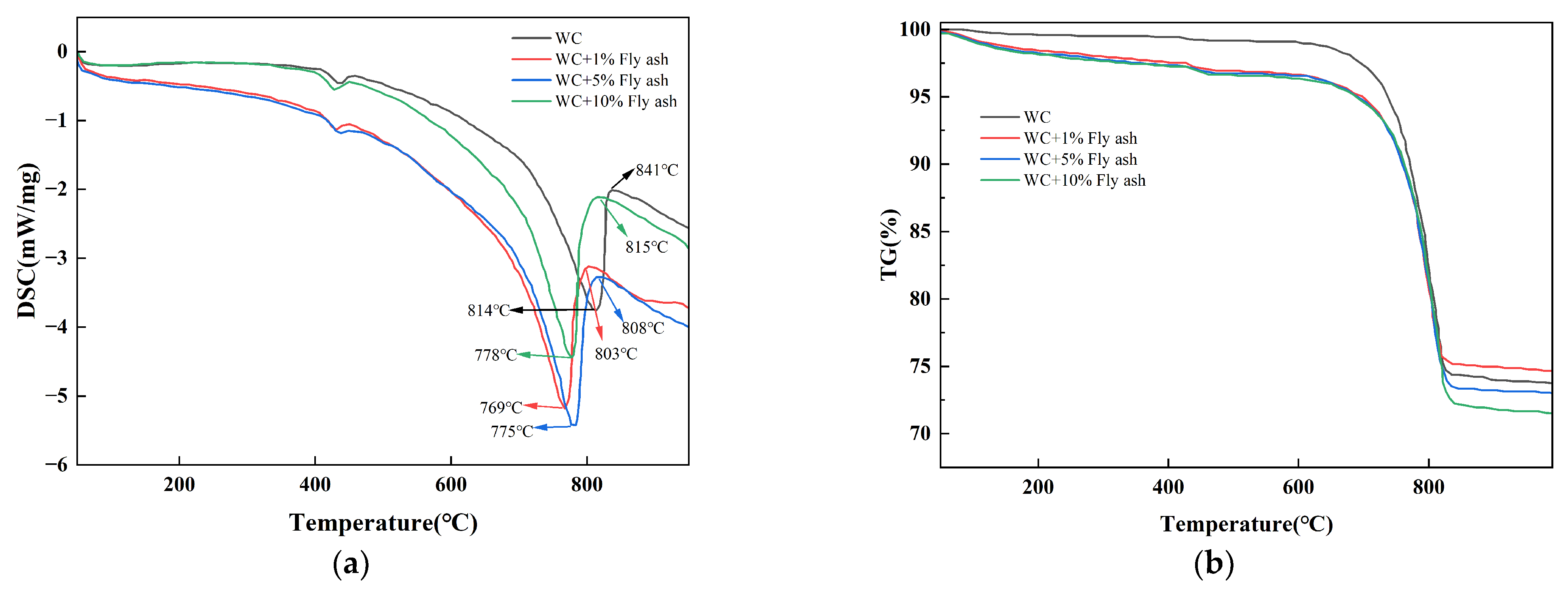
3.1. Materials Activation

Figure 2 shows the DSC-TG curves for 0%, 1%, 5%, and 10% fly ash mixed with waste concrete, and Table 4 shows the kinetic parameters of thermal decomposition. According to them, the thermal degradation process of fly ash and the waste concrete combination is fundamentally comparable to that of waste concrete. In comparison to concrete waste without fly ash, the temperatures at which the thermal decomposition of calcium carbonate occurs in waste concrete containing 1%, 5%, and 10% fly ash were, respectively, lowered by 39 °C, 34 °C, and 27 °C. This indicates that the addition of fly ash can bring down the decomposition temperature of calcium carbonate in waste concrete.
Figure 3 depicts the XRD patterns of the calcination products of waste concrete and a 10% fly ash combination. When the calcination temperature is 600 °C, two diffraction peaks of CaCO3 and SiO2 appear; when the calcination temperature is 800 °C, the new substance CaAl2O4 appears due to the reaction of CaO and Al2O3; and when the calcination temperature is 900 °C, the diffraction peak of Ca5Al6O14 appears, and the decomposition of calcium carbonate is essentially completed at the same time [22,23]. This reaction can be simplified into several stages, as given in Equations (2)–(4).
CaCO 3 CaO + CO 2   ( 600 900   ° C )
CaO + Al 2 O 3 CaAl 2 O 4   ( 800   ° C )
2 CaO + 3 CaAl 2 O 4 Ca 5 Al 6 O 14   ( 900 1000   ° C )
The thermogravimetric study revealed that fly ash might lower the breakdown temperature of calcium carbonate in waste concrete. XRD examination revealed the formation of two new compounds, CaAl2O4 and Ca5Al6O14, following the calcination of the combination. Analysing the mechanism of action of fly ash, due to the low purity of calcium carbonate in waste concrete, it gradually transformed from high grade to low grade, and CaO reacted with SiO2 and Al2O3 in fly ash in the solid phase, which enhanced the vitality of calcium carbonate decomposition by lowering the temperature at which it decomposed.

3.2. Compressive Strength

Table 5 and Figure 4 show the variation curves of compressive strength and strength as a function of the calcium–silicon ratio of the specimens under different curing conditions. The compressive strength of the specimens is significantly affected by the curing conditions. First, the overall compressive strength of the specimens increased with the calcium–silicon ratio over a range of autoclave holding times. Second, the compressive strength of the specimens increased in general as the autoclave holding duration increased from 3 to 9 h at 1.0 Mpa pressure. This difference in strength, however, was less significant, and the calcium–silicon ratio was higher at 1.0 Mpa. The compressive strength of the specimen declines with increasing insulation time when the pressure is 1.5 Mpa or 2.0 Mpa at 3 h for optimal autoclave insulation duration. The compressive strength of the specimen with a calcium–silicon ratio of 0.9 is the highest when the pressure is 1.5 Mpa, and when the pressure is 2.0 Mpa, the compressive strength of the specimen will generally increase as the calcium–silicon ratio increases (Table 6). The compressive strength of test blocks under different autoclaved systems (Mpa).

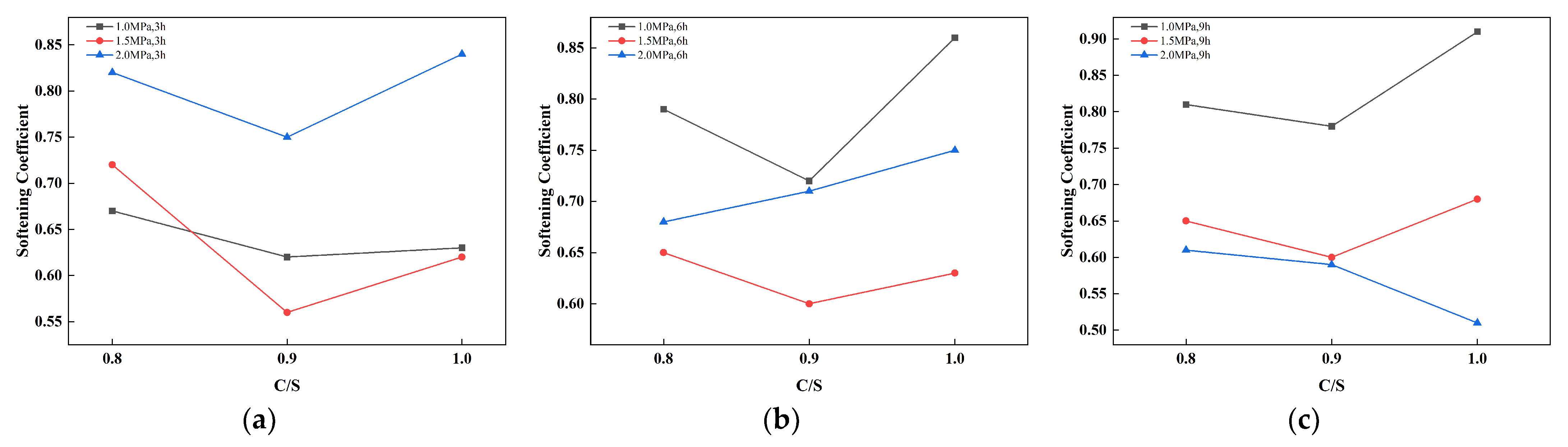
3.3. Water Resistance Analysis

Table 6 and Figure 5 show the test results of softening coefficient of pressure-steamed specimens and the curves of softening coefficient of specimens with a different calcium-to-silicon ratio under different steaming regimes. The water resistance is closely related to the autoclaved system. The water resistance of the specimens under 2 Mpa pressure was good at a 3 h holding time; the water resistance of the specimens under 1 Mpa pressure was good at a 6 h and 9 h holding time. The softening coefficient of the specimen gradually increases with the increase in the holding time when the steam pressure is 1 Mpa and 1.5 Mpa. This is because when the steam pressure is low, the internal material transformation process is very slow with the increase in the holding time, and the low alkaline hydration products are generated throughout the steam process, and the products have good crystallinity and less internal defects at this time, so the softening coefficient is large. When the evaporation pressure is 2 Mpa, with the increase in holding time, the softening coefficient shows a decreasing trend, which is due to the use of high pressure for evaporation, which makes the internal surface of calcium silica products have a large pressure difference, the internal micro cracks of calcium silica products, under the action of water, and the cohesion between particles are reduced, the colloid is diluted and softened by water, the small cracks originally produced are gradually expanded, and the bonding force between crystals is weakened, resulting in the strength of water immersion gradually decreases, so the softening coefficient gradually decreases [24,25,26].
The calcium–silica ratio has a certain influence on the water resistance [27,28]. When the calcium–silica ratio rises from 0.8 to 0.9, the softening coefficient of the specimen becomes smaller, that is, the strength of the specimen after water immersion decreases. This is because the calcium silica products immersed in water and saturated, under the action of water molecules, the material intermolecular gravitational force decreases; at the same time, the calcium–silica ratio increases, the calcium material content increases, and calcium silica products in the free calcium oxidize more, which will form more highly alkaline hydration products, resulting in reduced strength. When the calcium–silica ratio rises from 0.9 to 1.0, the softening coefficient of the specimen becomes larger, which is due to the fact that a small amount of fly ash is mixed into the calcium–silica products, which makes them have certain water hardness.

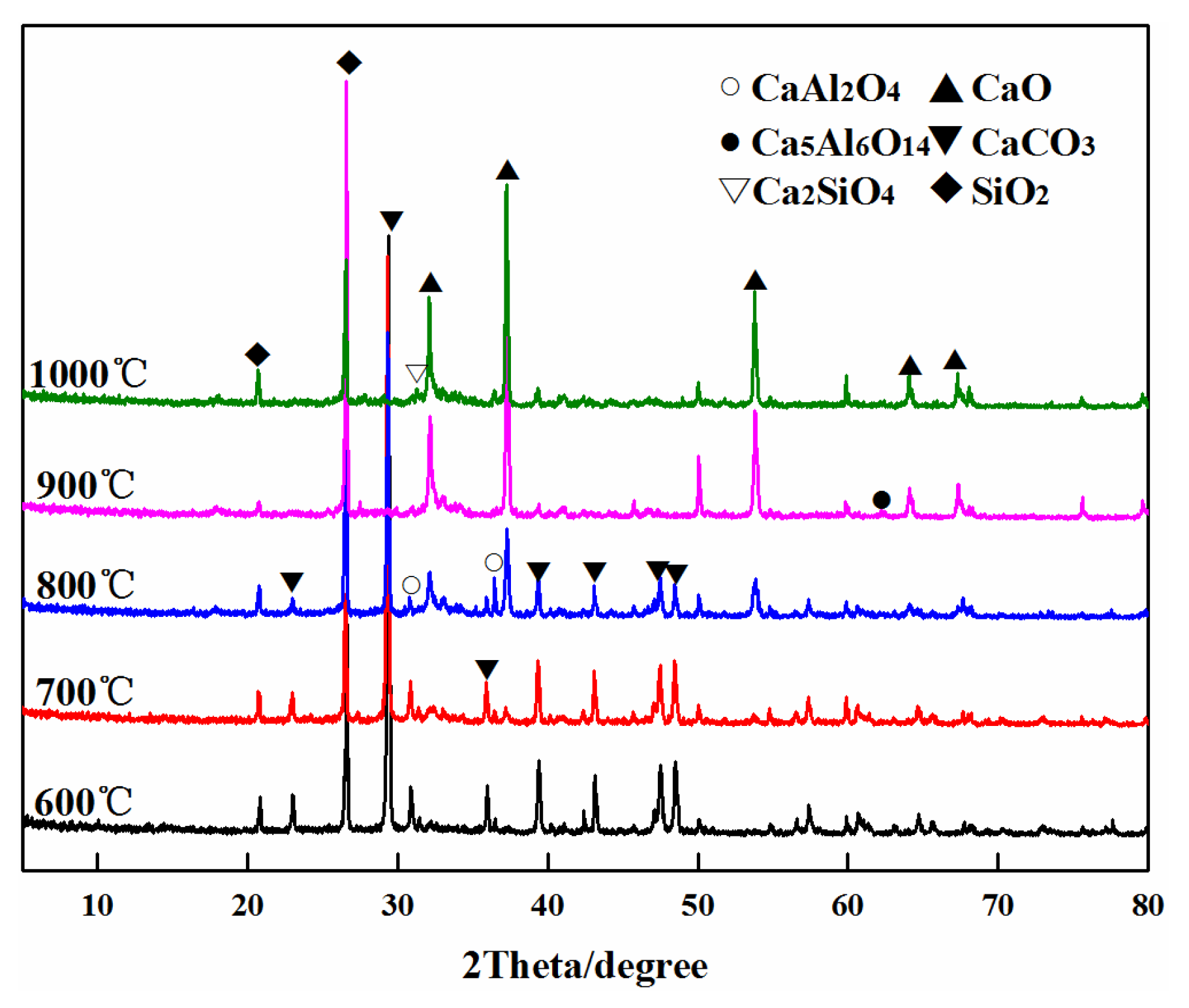
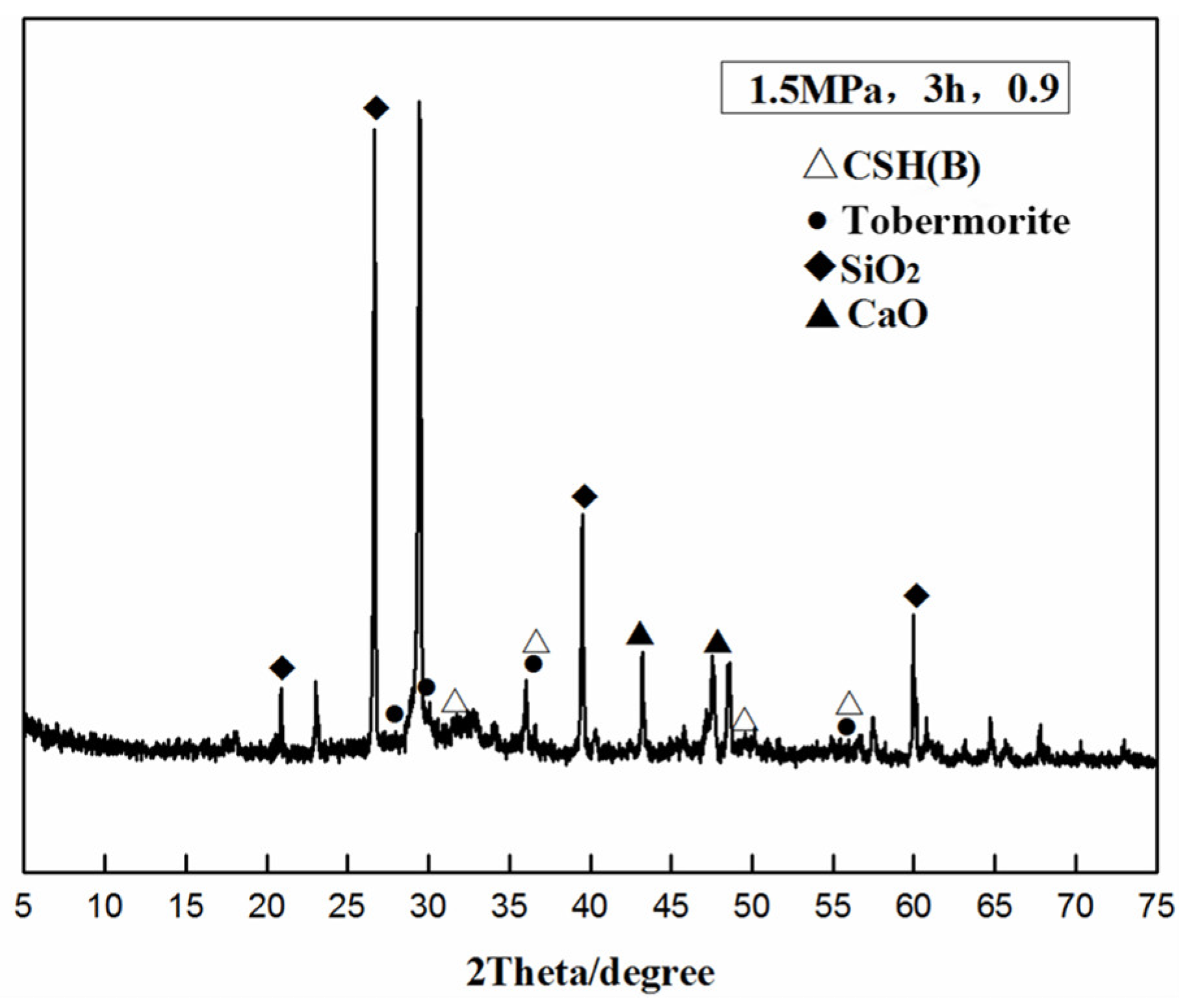
3.4. XRD Phase Analysis

Figure 6 depicts the XRD pattern of autoclaved sample R2P2T1. Although there are still evident peaks of siliceous and calcareous raw materials, which show that the holding period is too short and CaO and SiO2 do not react entirely, it can be observed that tobermorillonite and CSH(B) are the principal by-products of pressure cooking.
The strength of calcium silica products will decrease in the same autoclave system when the calcium silicon is relatively large, that is, when the calcium raw material content is high. The product will appear to be f-CaO and α-C2SH, and another double alkaline hydrated calcium silicate content will increase, and the high alkali type hydrated calcium silicate itself has a lower strength than mullite. Due to this, the specimen with a calcium–silica ratio of 1.0 exhibits less strength than the specimen with a calcium–silica ratio of 0.9.

3.5. SEM Analysis

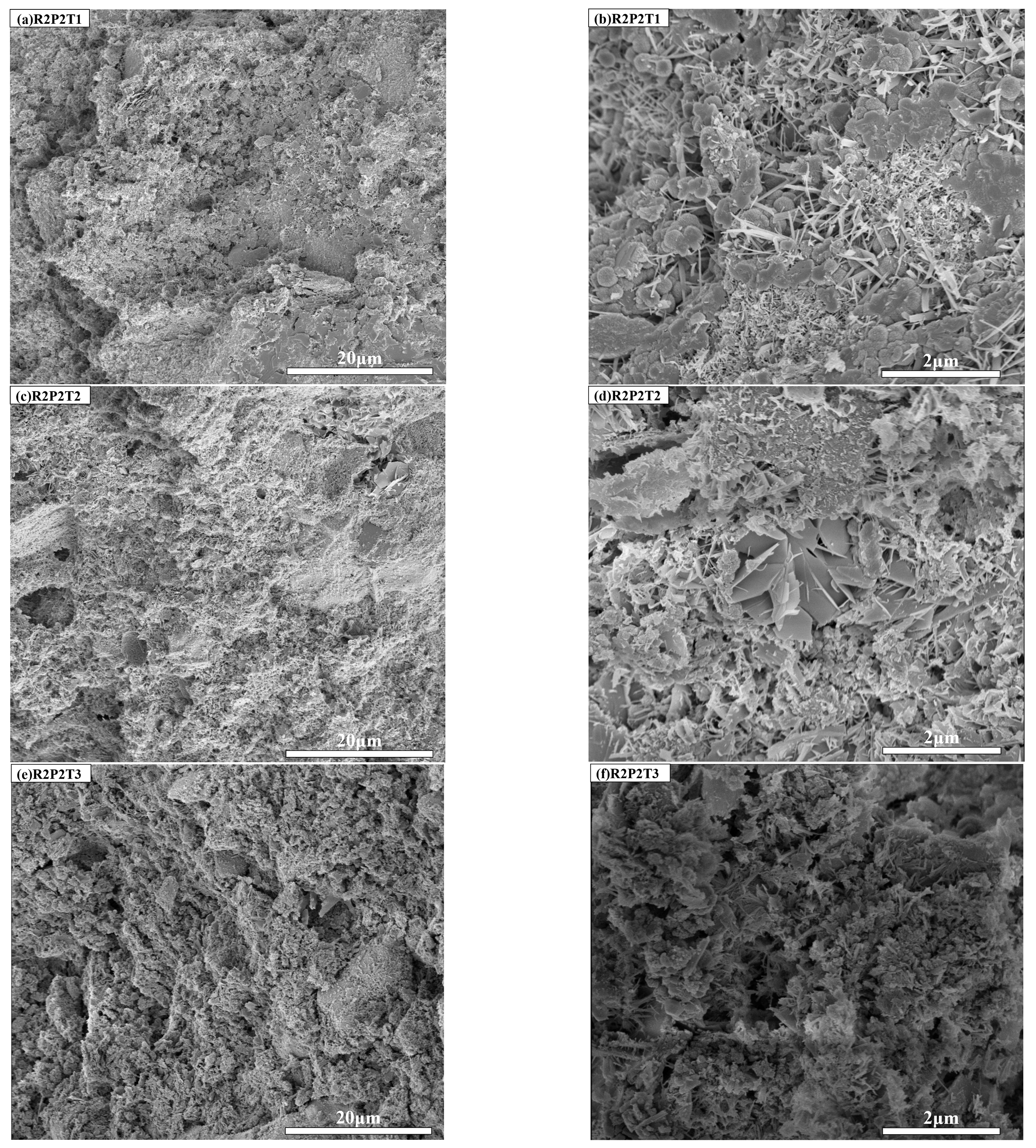
3.5.1. Influence of Steaming Holding Time

Figure 7 shows the SEM images of the autoclaved specimens R2P2T1, R2P2T2 and R2P2T3 at different holding times. When the holding time is 3 h, the unreacted fly ash particles and fibrous hydration products C-S-H gel can be clearly seen in Figure 7a,b, indicating that the siliceous raw materials are not completely dissolved at this time; compared with R2P2T2 and R2P2T3, the microstructure of R2P2T1 is the most dense, and the fibrous C-S-H gel is interwoven and filled with pores, which is consistent with the strength test results in Table 6, the strength of the specimens held for 3 h was the highest. As seen from Figure 7c,d, when the holding time is 6 h, the fibrous C-S-H gel in R2P2T2 is partially transformed into platelet tolbert mullite and coexists with both, and the fly ash particles disappear, indicating that the siliceous material is completely dissolved in the liquid phase. As seen from Figure 7e,f, when the holding time was 9 h, the hydrated calcium silicate in R2P2T3 changed from an amorphous compound at the beginning to well-crystallized tolbert mullite with a denser structure and reduced pores than R2P2ZT, which is also consistent with the strength test results in Table 6. The strength of the pressure-steamed specimens with a holding time of 9 h was higher than that of the specimens with a holding time of 6 h.

3.5.2. Influence of Autoclave Pressure

Figure 8 shows the SEM images of the autoclaved specimens R2P1T2, R2P2T2, and R2P3T2 under different pressures. From Figure 8a–d, it can be seen that the hydration products of R2P1T2 are dominated by gel-like C-S-H gels, and the hydration products of R2P2T2 are dominated by fibrous CSH(B) and plate-like tobermorillonite, indicating that the C-S-H gels gradually transformed tobermorillonite as the steam pressure increased, because the amorphous CSH(B) was not completely transformed into metamorphic tobermorillonite due to the short holding time. Because of the short holding time, the amorphous CSH(B) was not completely transformed into the well-crystallized plate-like tobermorillonite, making the simultaneous existence of CSH(B) and tobermorillonite in R2P2T2. At the same time, both have low vapor pressure and few hydration products, resulting in the strength not exceeding 30 MPa. Comparing a, b and c, d, R2P2T2 has pores of different sizes, and R2P1T2 has a small pore size and uniform pore distribution, indicating that the internal structure of R2P1T2 is denser than R2P2T2, so, macroscopically, the strength of R2P2T2 is slightly lower than that of R2P1T2. As seen from Figure 8e,f, the specimen with a calcium–silica ratio of 0.9, R2P3T2, formed completely hard silica–calcite crystals.
Compared with the synthesis of tobermorite [13], it is relatively difficult to form hard calcium silicate, which requires few raw material impurities, accurate ratios, high synthesis temperature, and long synthesis time, while this experiment synthesized hard calcium silicate using a laboratory autoclave with a short holding time, indicating that it is possible to synthesize tobermorite using calcined waste concrete as raw material not only hydrothermally, but also to synthesize hard calcium silicate with more complicated process requirements.

3.5.3. Influence of Calcium–Silica Ratio

Figure 9 shows the SEM images of the autoclaved specimens R1P2T3, R2P2T3 and R3P2T3 with different calcium–silica ratios. As can be seen from Figure 8a,b, the coexistence of fibrous C-S-H gels with plate-like tobermorites in R1P2T3 indicates that no well-crystallized tobermorites were formed due to the low calcium–silica ratio [13], resulting in reduced strength. Compared with R2P2T3, the latter formed hydrated calcium silicate as well-crystallized tobermorite with a denser structure, which macroscopically shows that R2P2T3 has higher strength. As seen in Figure 9c,d, the amount of tobermorite in the product of R3P2T3 decreased when the calcium–silica ratio increased to 1.0, which is because the optimal condition for the formation of tobermorite is a calcium–silica ratio of 0.88, and too high or too low a calcium–silica ratio affects the amount of tobermorite in the product of aqueous solution. In addition to the formation of more hydration products in R3P2T3, a small amount of needle-like hard calcium silica, C-S-H crystals and tobermorite were found, and the three occluded and firmly bonded to each other to form crystalline isotopes and hard monoliths, making the strength of the pressure steam specimen with a calcium–silica ratio of 1.0, 10 MPa higher than that of the specimen with a calcium–silica ratio of 0.9.

4. Conclusions

In this study, waste concrete autoclaved silicate material is utilized as a sustainable and environmentally friendly building material for reuse. Fly ash is added as an additive to enhance the thermal activation of the waste concrete matrix and to determine the optimal ratio of fly ash to waste concrete. The hydrothermal synthesis method is used to investigate the feasibility of calcined waste concrete as an autoclaved material. Based on the experimental results, we draw the following main conclusions.
The addition of fly ash decreased the thermal decomposition temperature of calcium carbonate in waste concrete in comparison to calcined waste concrete lacking fly ash. Nonetheless, as the quantity of fly ash added increased, the impact of lowering the thermal decomposition temperature of calcium carbonate became progressively weaker. The optimum results, which reduced the thermal decomposition temperature of calcium carbonate in waste concrete by 39 °C, were obtained by incorporating 1% fly ash.
The compressive strength of the specimens typically rises with the rise in calcium–silicon ratio and pressure, and attains a maximum value of 43.98 Mpa. It is, however, essential to adjust the holding duration according to the autoclave pressure. Higher pressure necessitates shorter holding time, while lower pressure requires longer holding time.
The overall softening coefficient of the specimens tends to decrease initially and then increase when the Ca/Si ratio increases from 0.8 to 1.0. At a pressure of 1.0 Mpa, the softening coefficient shows clear growth with longer holding times, with 9 h being the optimum time. However, at pressures of 1.5 Mpa or 2.0 Mpa, the effect of holding time is not significant, and 3 h is considered the ideal time. Generally speaking, most of the autoclaved specimens’ softening coefficient is greater than 0.6, indicating that the specimens have qualified water resistance.
The SEM images demonstrate that hydrated calcium silicate in the specimen changes from fibrous C-S-H gel at the beginning to the coexistence of C-S-H gel and plate-like tobermorite, and then produces well-crystallized tobermorite; similarly, it changes from internal product type C-S-H gel at the beginning to the coexistence of C-S-H gel and plate-like tobermorite at the end of autoclaving; The quantity of tobermorite in the specimen reduces as the calcium–silica ratio rises, and a little amount of hard calcium silicate, C-S-H crystals and tobermorite bond together to create a crystalline conjoined body and a hard whole, greatly enhancing the specimen’s strength. The macroscopic strength is dictated by the way the microstructure of hydration products forms under varied circumstances.
The optimal mould design pressure, holding time, and calcium–silicon ratio should be 1.0 Mpa, nine hours, and 1.0 Mpa, respectively, based on the findings of compressive strength, water resistance, and microscopic inspection. With the ideal water resistance line and a more stable microstructure, it can attain a compressive strength of 32.69 Mpa in this instance. In addition, it minimizes energy use and its negative effects on the environment while satisfying the needs of real-world applications.

Author Contributions

H.A.: conceptualization, validation, resources, writing—review and editing, supervision. F.M.: methodology, formal analysis, investigation, writing—original draft. All authors have read and agreed to the published version of the manuscript.

Funding

This research received no external funding.

Institutional Review Board Statement

The authors declare that they have no known competing financial interests or personal relationships that could have appeared to influence the work reported in this paper.

Informed Consent Statement

Informed consent was obtained from all subjects involved in the study. Written informed consent has been obtained from the patient(s) to publish this paper.

Data Availability Statement

The authors confirm that the data supporting the findings of this study are available within the article.

Conflicts of Interest

The authors declare no conflict of interest.

References

  1. Wang, R.; Zhang, Y.X. Recycling fresh concrete waste: A review. Struct. Concr. 2018, 19, 1939–1955. [Google Scholar] [CrossRef]
  2. Hao, J.L.; Yu, S.; Tang, X.; Wu, W. Determinants of workers’ pro-environmental behaviour towards enhancing construction waste management: Contributing to China’s circular economy. J. Clean. Prod. 2022, 369, 133265. [Google Scholar] [CrossRef]
  3. Xiao, J.; Ma, Z.; Ding, T. Reclamation chain of waste concrete: A case study of Shanghai. Waste Manag. 2016, 48, 334–343. [Google Scholar] [CrossRef] [PubMed]
  4. Hong, J.; Zhong, X.; Guo, S.; Liu, G.; Shen, G.Q.; Yu, T. Water-energy nexus and its efficiency in China’s construction industry: Evidence from province-level data. Sustain. Cities Soc. 2019, 48, 101557. [Google Scholar] [CrossRef]
  5. Jebelli, H.; Choi, B.; Lee, S. Application of Wearable Biosensors to Construction Sites. I: Assessing Workers’ Stress. J. Constr. Eng. Manag. 2019, 145, 04019079. [Google Scholar] [CrossRef]
  6. Du, Q.; Zhao, L.; Zhao, L.; Guo, Y. Technical and economic feasibility of construction and demolition waste used in road construction. In Proceedings of the 2011 International Symposium on Water Resource and Environmental Protection (ISWREP), Xi’an, China, 20–22 May 2011; Wang, W., Ed.; IEEE: Piscataway, NJ, USA, 2011; p. 8, ISBN 978-1-61284-339-1. [Google Scholar]
  7. Wang, Y.; Zheng, J.; You, F. Review on Enhancement Methods of Recycled Aggregate. Mater. Rev. 2021, 35, 5053–5061. [Google Scholar]
  8. Kim, J. Influence of quality of recycled aggregates on the mechanical properties of recycled aggregate concretes: An overview. Constr. Build. Mater. 2022, 328, 127071. [Google Scholar] [CrossRef]
  9. Wang, C.; Cheng, L.; Huang, Q.; Shui, Z.; Liu, Y.; Zhao, H.; Zhang, Z. Basic performance, heavy metal leaching mechanism and risk assessment analysis of waste concrete. Arch. Civ. Mech. Eng. 2023, 23, 1–24. [Google Scholar] [CrossRef]
  10. Tang, Q.; Ma, Z.; Wu, H.; Wang, W. The utilization of eco-friendly recycled powder from concrete and brick waste in new concrete: A critical review. Cem. Concr. Compos. 2020, 114, 103807. [Google Scholar] [CrossRef]
  11. Shandilya, M.; Rai, R.; Singh, J. Review: Hydrothermal technology for smart materials. Adv. Appl. Ceram. 2016, 115, 354–376. [Google Scholar] [CrossRef]
  12. Zhao, Q.; Wang, Z.; Xu, X.; Cui, C.; Zhang, S.; Ding, X. Research Status of Structures, Thermal Behavior and Synthesis of Tobermorite. J. Chin. Ceram. Soc. 2020, 48, 1536–1551. [Google Scholar]
  13. Yang, X.; Cui, X.; Cui, C.; Ma, H.; Yang, Q. Study on High-Temperature Phase Change of Tobermorite. Spectrosc. Spectr. Anal. 2013, 33, 2227–2230. [Google Scholar]
  14. Bao, M.; Guo, X.; Shi, H. Research progress on hydrothermal synthesis of tobermorite whisker and its high temperature resistance. J. Funct. Mater. 2017, 48, 11075–11080, 11085. [Google Scholar]
  15. Galvankova, L.; Masilko, J.; Solny, T.; Stepankova, E. Tobermorite synthesis under hydrothermal conditions. Procedia Eng. 2016, 151, 100–107. [Google Scholar] [CrossRef]
  16. Wang, Z.; Chen, Y.; Xu, L.; Zhu, Z.; Zhou, Y.; Pan, F.; Wu, K. Insight into the local C-S-H structure and its evolution mechanism controlled by curing regime and Ca/Si ratio. Constr. Build. Mater. 2022, 333, 127388. [Google Scholar] [CrossRef]
  17. Yi, L.; Wang, H.; Wang, X.; Peng, J. Research Progress of Utilizing Fly Ash as Resource of Building Material. Bull. Chin. Ceram. Soc. 2012, 31, 88–91. [Google Scholar]
  18. Qian, J.; Ji, X.; Fan, Y.; Wang, Z. The Formation and Effect of Calcic Minerals in Fly Ash. J. Chongqing Jianzhu Univ. 2008, 30, 148–152. [Google Scholar]
  19. Wang, Y.; Burris, L.; Hooton, R.D.; Shearer, C.R.; Suraneni, P. Effects of unconventional fly ashes on cementitious paste properties. Cem. Concr. Compos. 2022, 125, 104291. [Google Scholar] [CrossRef]
  20. Liu, B.; Yang, L.; Shi, J.; Zhang, S.; Yalcinkaya, C.; Alshalif, A.F. Effect of curing regime on the immobilization of municipal solid waste incineration fly ash in sustainable cement mortar. Environ. Pollut. 2023, 317, 120839. [Google Scholar] [CrossRef]
  21. GB/T4111-2013; Test Methods for the Concrete Block and Brick. National Standards of People’s Republic of China: Beijing, China, 2013.
  22. Calvo, E.G.; Arranz, M.A.; Leton, P. Effects of impurities in the kinetics of calcite decomposition. Thermochim. Acta 1990, 170, 7–11. [Google Scholar] [CrossRef]
  23. Liu, C.; Han, K.; Wang, D. An In Situ Decarbonation Kinetic Study of Calcite Using Synchrotron Radiation XRD. Can. Mineral. 2022, 60, 687–698. [Google Scholar] [CrossRef]
  24. Myers, R.; L’Hôpital, E.; Provis, J.; Lothenbach, B. Effect of temperature and aluminium on calcium (alumino)silicate hydrate chemistry under equilibrium conditions. Cem. Concr. Res. 2015, 68, 83–93. [Google Scholar] [CrossRef]
  25. Palubinskaite, D.; Kantautas, A. Influence of tribomechanical milling and activation of primary mixtures on the synthesis of calcium silicate hydrates. Mater. Sci.-Pol. 2006, 24, 395–403. [Google Scholar]
  26. Mostafa, N.Y.; Shaltout, A.A.; Omar, H.; Abo-El-Enein, S.A. Hydrothermal synthesis and characterization of aluminium and sulfate substituted 1.1nm tobermorites. J. Alloys Compd. 2009, 467, 332–337. [Google Scholar] [CrossRef]
  27. Tränkle, S.; Jahn, D.; Neumann, T.; Nicoleau, L.; Hüsing, N.; Volkmer, D. Conventional and microwave assisted hydrothermal syntheses of 11 Å tobermorite. J. Mater. Chem. A 2013, 1, 10318–10326. [Google Scholar] [CrossRef]
  28. Huang, X.; Jiang, D.; Tan, S. Novel hydrothermal synthesis of tobermorite fibers using Ca(II)-EDTA complex precursor. J. Eur. Ceram. Soc. 2003, 23, 123–126. [Google Scholar] [CrossRef]
Figure 1. Pictures from raw material to after moulding. (a) Waste concrete mix; (b) calcined waste concrete powder; (c) test specimens after autoclave curing.
Sustainability 15 16341 g001
Figure 2. DSC-TG curves of calcined waste concrete mixed with fly as. (a) DSC curves after calcination of the mix; (b) TG curves after calcination of the mix.
Sustainability 15 16341 g002
Figure 3. XRD of calcined waste concrete plus fly ash.
Sustainability 15 16341 g003
Figure 4. Effect of calcium–silicate ratio on compressive strengthen under different autoclaved systems. (a) Compressive strength of the specimens after holding for 3 h; (b) compressive strength of the specimens after holding for 6 h; (c) compressive strength of the specimens after holding for 9 h.
Sustainability 15 16341 g004
Figure 5. The curve of softening coefficient changing with the ratio of calcium to silicon. (a) Softening coefficient of the specimens after holding for 3 h; (b) softening coefficient of the specimens after holding for 6 h; (c) softening coefficient of the specimens after holding for 9 h.
Sustainability 15 16341 g005
Figure 6. XRD pattern of autoclaved specimens (1.5 MPa, 3 h, C/S = 0.9).
Sustainability 15 16341 g006
Figure 7. SEM of samples with different autoclave holding times.
Sustainability 15 16341 g007
Figure 8. SEM of samples with different vapor pressure.
Sustainability 15 16341 g008aSustainability 15 16341 g008b
Figure 9. SEM of samples with different calcium to silicon ratios (C/S).
Sustainability 15 16341 g009
Table 1. Mixture design of concrete (wt.%).
ComponentsCementCrushed StoneRiver SandWater
Weight (Kg)4401108638215
Matching ratio12.521.450.49
Basic material parametersP.O 42.5Dmax = 20 mm
Table 2. Chemical composition of materials (wt.%).
ComponentsCaOSiO2Al2O3Fe2O3MgOSO3K2OSrOLOI
WC47.3919.021.610.971.270.780.490.1028.24
Fly ash9.851.4924.365.491.22.14\\2.34
Table 3. Specimen number under different conditions (R 1 P 2 T 3).
C/S1.0 MPa1.5 MPa2.0 MPa
3 h6 h9 h3 h6 h9 h3 h6 h9 h
0.8R1P1T1R1P1T2R1P1T3R1P2T1R1P2T2R1P2T3R1P3T1R1P3T2R1P3T3
0.9R2P1T1R2P1T2R2P1T3R2P2T1R2P2T2R2P2T3R2P3T1R2P3T2R2P3T3
1.0R3P1T1R3P1T2R3P1T3R3P2T1R3P2T2R3P2T3R3P3T1R3P3T2R3P3T3
1 calcium–silica ratio. 2 pressures. 3 holding time.
Table 4. Thermal decomposition of waste concrete plus fly ash.
ComponentsStarting Temperature (°C)Peak Temperature (°C)End Temperature (°C)
WC647814841
WC + 1% Fly ash616769803
WC + 5% Fly ash602775808
WC + 10% Fly ash604778815
Table 5. The compressive strength of test blocks under different autoclaved systems (Mpa).
C/S1.0 Mpa1.5 Mpa2.0 Mpa
3 h6 h9 h3 h6 h9 h3 h6 h9 h
0.818.6223.7734.0228.9220.6222.1333.5927.0421.71
0.926.9128.1134.6442.5322.8125.8933.0131.7823.63
1.031.9433.3932.6938.7423.1734.6243.9836.6726.51
Table 6. The softening coefficient of test blocks under different autoclaved systems.
C/S1.0 Mpa1.5 Mpa2.0 Mpa
3 h6 h9 h3 h6 h9 h3 h6 h9 h
0.80.670.790.810.720.650.650.820.680.61
0.90.620.720.780.560.60.60.750.710.59
1.00.630.860.910.620.630.680.840.750.51
Disclaimer/Publisher’s Note: The statements, opinions and data contained in all publications are solely those of the individual author(s) and contributor(s) and not of MDPI and/or the editor(s). MDPI and/or the editor(s) disclaim responsibility for any injury to people or property resulting from any ideas, methods, instructions or products referred to in the content.

