Article

Geosynthetic Solutions for Sustainable Transportation Infrastructure Development

School of Civil, Architectural Engineering, and Landscape Architecture, Sungkyunkwan University, Suwon 16419, Republic of Korea
Sustainability 2023, 15(22), 15772; https://doi.org/10.3390/su152215772
Submission received: 17 May 2023 / Revised: 9 June 2023 / Accepted: 20 October 2023 / Published: 9 November 2023
(This article belongs to the Special Issue Sustainability and Innovation in Transport Infrastructure Geotechnics)

Abstract

:
Geosynthetic engineering has made significant advances during the past decade in the areas of manufacturing and practical applications. As a result, geosynthetics have become essential materials that facilitate construction, better improve short- and long-term performance, and reduce long-term maintenance costs in routine civil engineering projects. Geosynthetics are also being recognized as fundamental to sustainable infrastructure development as they reduce the carbon footprint generated by infrastructure development by minimizing the use of natural construction materials. Creative use of geosynthetics in geo-engineering practices is expected to continue to expand as innovative materials and products are becoming available. In this paper, we begin by discussing issues related to climate change. The sustainable benefits of geosynthetics are then presented by demonstrating the potential of geosynthetics to significantly reduce carbon footprints compared to traditional solutions. Finally, recent geosynthetic technologies have been introduced for use in transportation infrastructure. The pathway forward of the geosynthetic technology is also discussed from the view of sustainable infrastructure development.

1. Introduction

Since the first geosynthetics conference in Paris in 1977, geosynthetics have become essential materials in routine civil engineering projects that better improve short- and long-term performance and reduce long-term maintenance costs. As indicated in the 9th Buchanan Lecture paper [1], significant development in civil engineering technology was accompanied by the development of new and innovative construction materials. One of the examples is concrete, reinforced concrete, and prestressed reinforced concrete technology, which have replaced wood and building stone as construction materials, that have allowed the construction of larger-scale structures. A similar example in geotechnical engineering is the advent of modern reinforced soil technology in which polymeric reinforcement materials provide an added level of tensile resistance and stability to soils that have little to no tensile strength, allowing larger-scale geo-structures to be built with greater confidence [1].
Sustainability has become a keyword in our daily lives as our built environment is being threatened by climate change. Despite the recent societal efforts to reduce the related risks, the viability of achieving environmental sustainability is still being questioned due to environmental degradation, climate change, overconsumption, population growth, and the continued pursuit of economic growth. As a result, human-induced climate change is already affecting people, ecosystems, and livelihoods around the world. For example, Tuvalu, one of the low-lying Pacific Island nations, is struggling to maintain its land due to rising sea levels, as the foreign secretary reported at COP26 (the United Nations (UN) climate conference in Glasgow). Commitment to sustainability will reduce the carbon footprint and the amount of toxins released into the environment. As will be discussed, the fact that the construction industry is one of the largest users of global resources and is a major contributor of pollution and greenhouse gas (GHG) emissions [2], places a heavy responsibility on the construction industry to reduce its carbon footprint from the viewpoint of sustainability.
This paper is an extended version of the previously published paper by the author [3]. In this paper, we discuss the benefits of geosynthetics to sustainability by demonstrating the potential of geosynthetics to significantly reduce the carbon footprint compared to traditional construction methods. Recent geosynthetic technologies for use in transportation infrastructure are highlighted in the context of recent trends and research outcomes in this area.

2. Climate Change: Implications for the Construction Industry

2.1. What We Know

Global temperatures have risen approximately 1.0 °C above pre-industrial levels, and if current rates are maintained, this will likely reach 1.5 °C between 2030 and 2052 [4]. However, limiting warming to the 1.5 °C global warming scenario requires unprecedented efforts from all sectors of human society. Related studies have revealed higher climate-related risks for natural and human systems at 1.5 °C of global warming than at present but lower risks than those at 2 °C (high confidence).
Consequences of climate change include an increase in global temperatures, rising sea levels, changing precipitation, and expansion of deserts [5]. These extreme weather events will likely be exacerbated due to insufficient societal response. The risks related to global warming depend on several factors such as magnitude and rate of warming, geographic location, levels of development and vulnerability, and more importantly, the choices and implementation of adaptation and mitigation options [6]. Figure 1 illustrates the worldwide present-day warming. As shown in the figure, nearly five billion people are experiencing greater than 1.0 °C of warming above pre-industrial levels during the warmest season of the year.
The urgency of an adequate response to the global GHG emissions has been well addressed by Ritchie and Roser [6]. They reported global GHG emission scenarios in terms of likely warming, as shown in Figure 2, where a range of potential future scenarios of global greenhouse gas emissions (measured in gigatons of carbon dioxide equivalents) is presented based on data from the Climate Action Tracker. When no climate policies are implemented, 4.1–4.8 °C warming is likely by 2100 (first scenario). With current climate policies (second scenario), global warming of 3.1–3.7 °C by 2100 is expected. If all countries achieve their current targets/pledges set within the Paris Climate Agreement (third scenario), an estimated average warming of 2.6–3.2 °C is likely by 2100, well beyond the overall target of the Paris Agreement to limit warming “well below 2.0 °C”. The fourth scenario involves the 2.0 °C pledge, limiting average warming to 2.0 °C by 2100. As one might guess, a significant increase in the ambition of current pledges within the Paris Agreement is required to achieve this goal. The last (fifth) scenario involves limiting average warming to 1.5 °C by 2100, which requires a very urgent and rapid reduction in global greenhouse gas emissions.

2.2. The UN Sustainability Goals

The UN sustainability goals (SDGs) were established by the UN in 2015, with a target date of 2030 [7]. Detailed action plans are included in the 17 SDGs to end poverty and protect the planet by 2030, as shown in Figure 3. As shown, all aspects of social, economic, and environmental sustainability are considered so that an action in one area will affect outcomes in others [8]. Some of the 17 SDGs are clearly supported by geosynthetics, particularly in the environmental and economic categories, including goals such as clean water and sanitation, clean energy, infrastructures, and sustainable cities [8,9,10].

2.3. Implications to the Construction Industry

According to the 2021 Global Status Report for Buildings and Construction [11], buildings and construction together account for 36% of the total global energy use and 37% of energy-related carbon dioxide (CO2) emissions, giving the construction industry a huge responsibility to implement specific action plans to achieve sustainable construction targets.
As the global population is expected to reach 8.5 billion people by the year 2030, preserving non-renewable resources is a top priority to ensure the planet’s survival. Sustainable solutions in construction industries are needed to deliver infrastructure that supports a desired quality of life for current and future generations while conserving resources and energy. Bringing sustainability to the construction industry is a challenging task that relies significantly on innovative materials and design/construction technologies. Through innovation, the construction industry can transition from being part of the problem to becoming part of the solution. According to Gourbran [12], 17% of the SDG targets are directly dependent, and 27% of the targets are indirectly dependent, on construction and real estate activities.
Geosynthetics provide sustainable solutions to routine civil/geotechnical works when dealing with projects involving soils, rocks, and similar materials, such as coal ashes and mine tailings, by minimizing the use of natural resources. For example, using geosynthetics allows the conservation of quarrying sand, load-bearing materials, and/or drainage aggregates (Figure 4). One truckload of geosynthetic clay liner (GCL) is equivalent to 150 truckloads of natural clay [13], which reduces the use of clay (a natural material) and impairment caused by traffic to and from construction sites (Figure 5).
Digital tools, such as Building Information Modeling (BIM) and Artificial Intelligence (AI), can also help achieve sustainable construction goals by optimizing construction processes for a given project (Figure 6). BIM, in particular, can greatly enhance project design efficiency and productivity on site while minimizing construction errors, thus reducing wasted time, materials, energy, and costs.
Recent related studies include the one by Raja and Shulka [14] in which a new hybrid technique for predicting the settlement of geosynthetic-reinforced soil foundations based on grey wolf optimization (GWO) and artificial neural network (ANN). Most recently, Chao et al. [15] published a paper concerning artificial intelligence algorithms for predicting the peak shear strength of clayey soil. These studies have demonstrated that AI also can be used as a design tool when generalized by relevant training data sets.
Undoubtedly, construction has played an important role in creating the built environment since the beginning of human civilization and will continue to be a key player in sustainable infrastructure development. The construction industry, however, needs to fully address and support sustainable development and climate action for current and future generations.

3. Geosynthetic Solutions in Transportation Infrastructure Development

Over the years, geosynthetic solutions have been well accepted in transportation infrastructure development as alternatives to conventional approaches. The use of geosynthetic solutions in transportation applications is expected to continue to grow due to their sustainable benefits and sound performance. This section reviews the technical background of several examples of geosynthetic solutions based on work by the author.

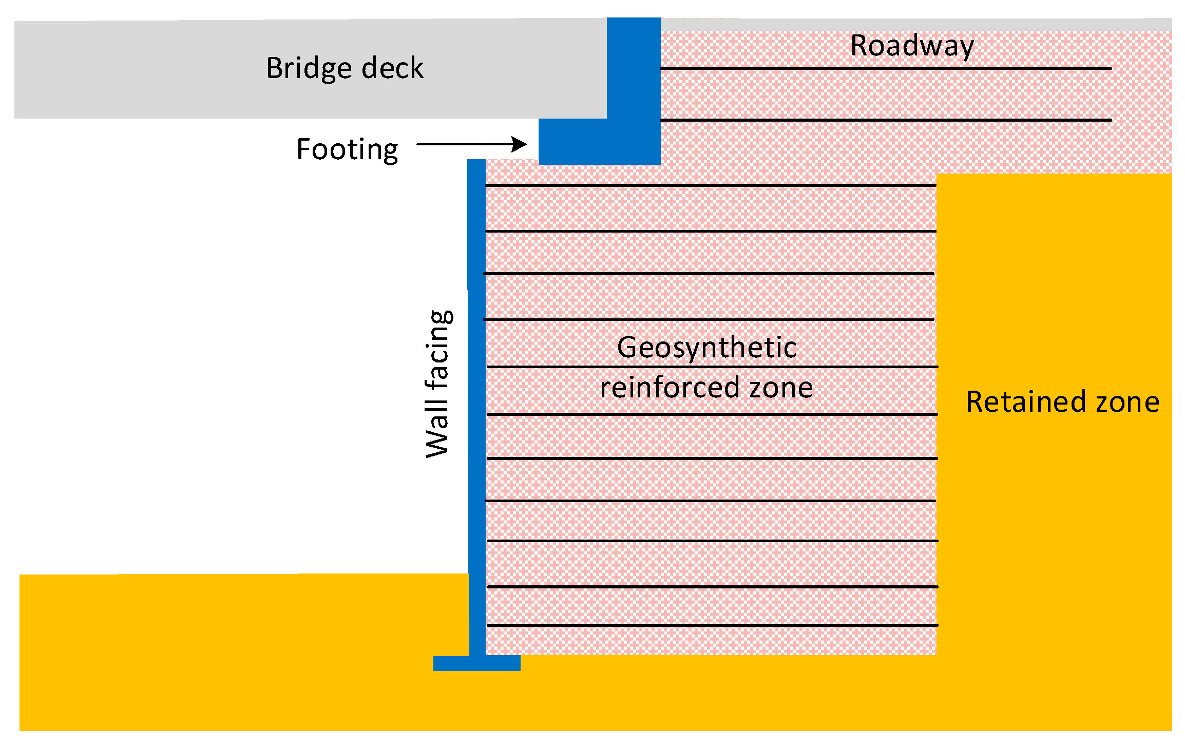
3.1. Geosynthetic Bridge Abutment

Geosynthetic reinforced soil (GRS) bridge abutments have been recognized as a viable alternative to the conventional concrete bridge abutment system in many countries. In fact, the GRS abutment is technically a surcharge-loaded geosynthetic-reinforced soil wall, as shown in Figure 7. One benefit, in addition to its sound performance, is its ability to alleviate the “bridge bump” caused by differential settling between the bridge abutment and approach way in a conventional concrete abutment [16,17].
In a typical GRS bridge abutment configuration, the abutment is loaded by the superstructure and traffic loading, which increases stresses in the reinforced soil mass. Due to the importance of the load-carrying capacity of the GRS abutment on its serviceability and stability, there have been a number of studies on this subject [18,19,20,21,22,23]
The load-carrying capacity of a surcharge-loaded GRS wall was demonstrated effectively by Yoo and Kim [18] based on the results of a full-scale load test on a 5 m high, two-tier GRS wall The test wall was loaded by a precast concrete (PC) box frame with dimensions of 2.4 m × 2.4 m in plan and 2.4 m in height. Ready-mixed concrete was added incrementally to the PC box frame. The completely filled box frame exerted a load of approximately 38 kN or 62 kPa on the reinforced soil mass, which was thought to induce stress levels within an operational condition. For details, readers should refer to prior work [18].
Figure 8 presents selected results reported by Yoo and Kim [18]. As shown in Figure 8b, the surcharge load induced less than 2 mm of facing displacement in the upper tier wall, although no provision was made for the surcharge load in the original wall design. The strains induced by the surcharge load in the top reinforcement layer also were minimal, i.e., less than 0.1%, with negligible reinforcement strains developed in the rest of the lower-tier reinforcement layers. Yoo and Kim [18] concluded that the surcharge load did not pose any threat to the internal stability of the test wall, even though the wall was not designed for the load, as the surcharge load-induced wall displacement and reinforcement strains were minimal.

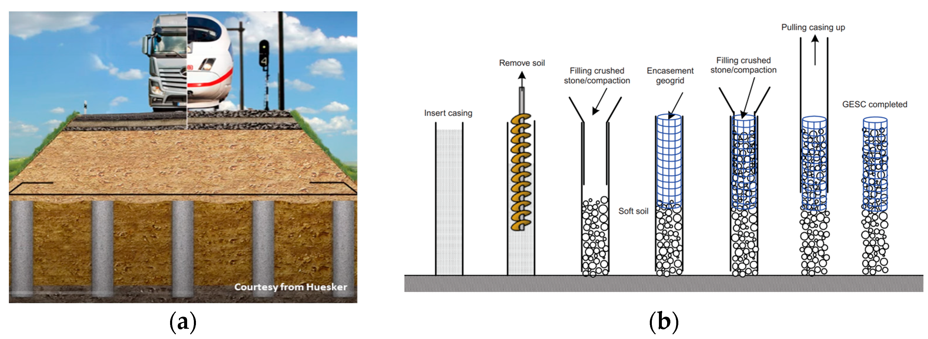
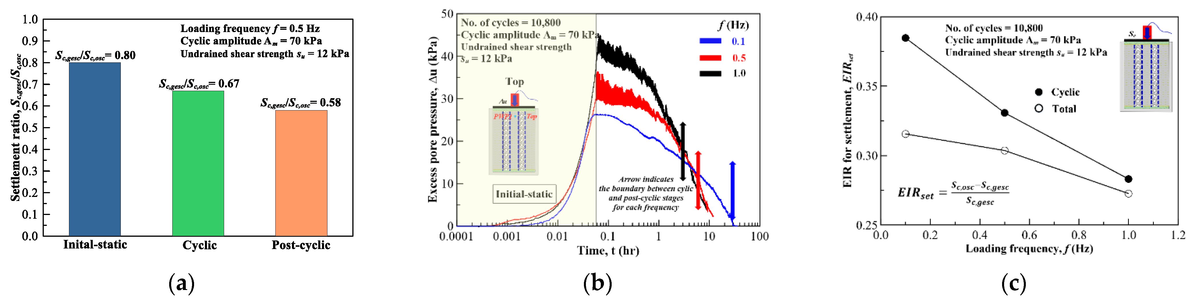
3.2. Geosynthetic-Encased Stone Column

The load-carrying capacity of an ordinary stone column (OSC) installed in soft ground can be significantly reduced as it tends to bulge due to the lack of lateral pressure from the surrounding soil required to maintain its stability. A number of studis [24,25,26,27,28,29,30,31,32,33,34] have demonstrated that a full or partial geosynthetic encasement of the stone column in such cases can significantly increase its loading capacity via the added level of confinement provided by the geosynthetic. Such a technique is referred to as geosynthetic encasement stone column (GESC) and is gaining wide acceptance (Figure 9).
More specifically, Yoo and Lee [25] performed a series of full-scale load tests on GESCs and an OSC to investigate the load-carrying capacity behavior of geogrid-encased stone columns. They reported, among other things, that a partial encasement, i.e., 0.2–0.4 D (D = column diameter), almost doubled the load-carrying capacity of the OSC, due mainly to the added confinement provided by the geogrid encasement (Figure 10).
When installed to support an embankment constructed in soft ground, GESCs improve the settlement characteristics of the embankment by accelerating pore water pressure dissipation caused by embankment loading, as reported by Yoo [26]. As shown in Figure 11b,c, a greater benefit of the geogrid encasement can be achieved when adopting a larger stiffness geosynthetic encasement due primarily to the decreased level of embankment load transferred to the original ground.
GESCs are frequently installed to support embankments for roadways and railway tracks, where the loading characteristics are mainly cyclic in nature, from moving vehicles. Yoo and Abbas [27] conducted a series of tests using a reduced-scale model and highlighted the GESE response to cyclic loading considering principal characteristics such as frequency, amplitude, and encasement stiffness, as summarized in Table 1.
In their study, the dependency of the load-carrying capacity of GESC on the cyclic loading characteristics was highlighted. For example, as shown in Figure 12, a greater benefit of geogrid encasement was observed in the settlement and post-cyclic load-carrying capacity behavior under lower frequency and/or smaller amplitude loading. It was also reported that the degree of load transfer to the column decreased as the loading frequency increased. They recommended the use of a decreased stress concentration ratio from the static case when subjected to higher frequency and/or higher amplitude loading.

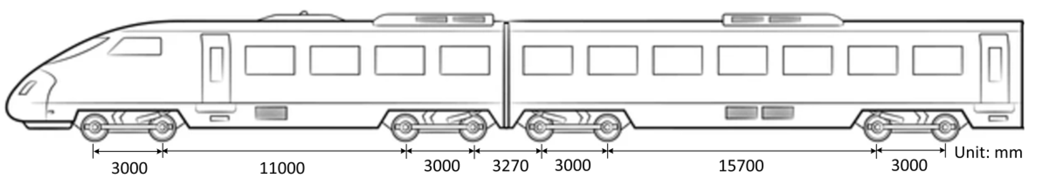
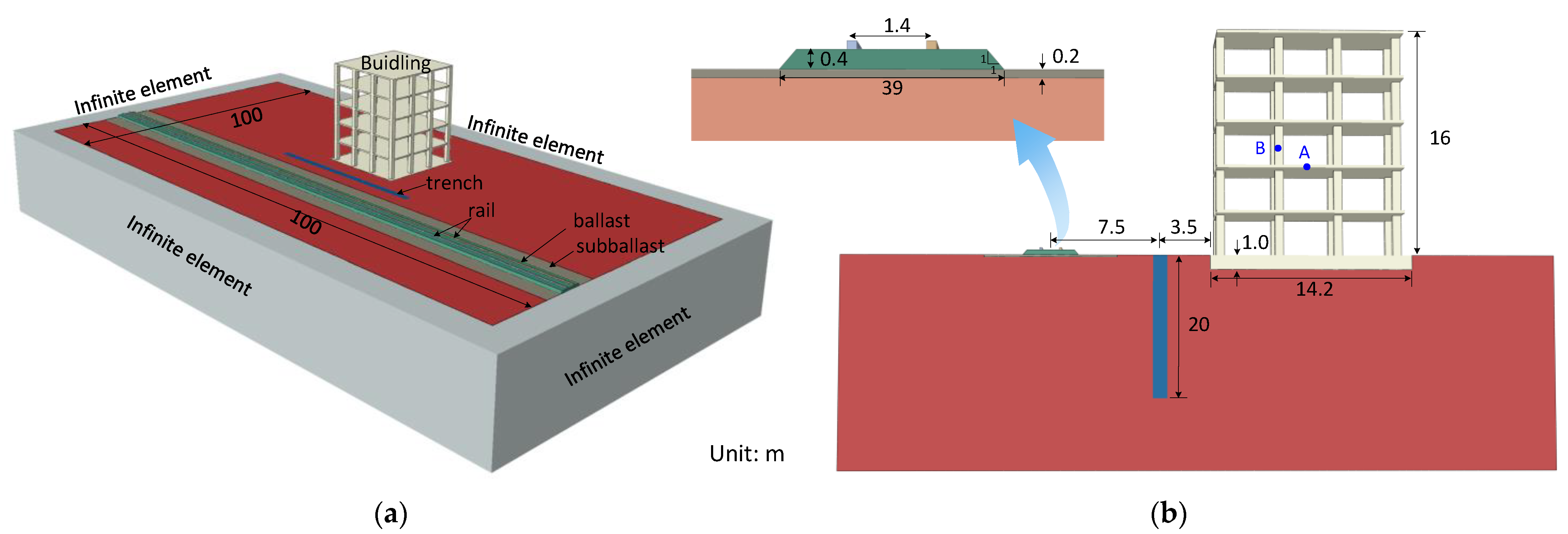
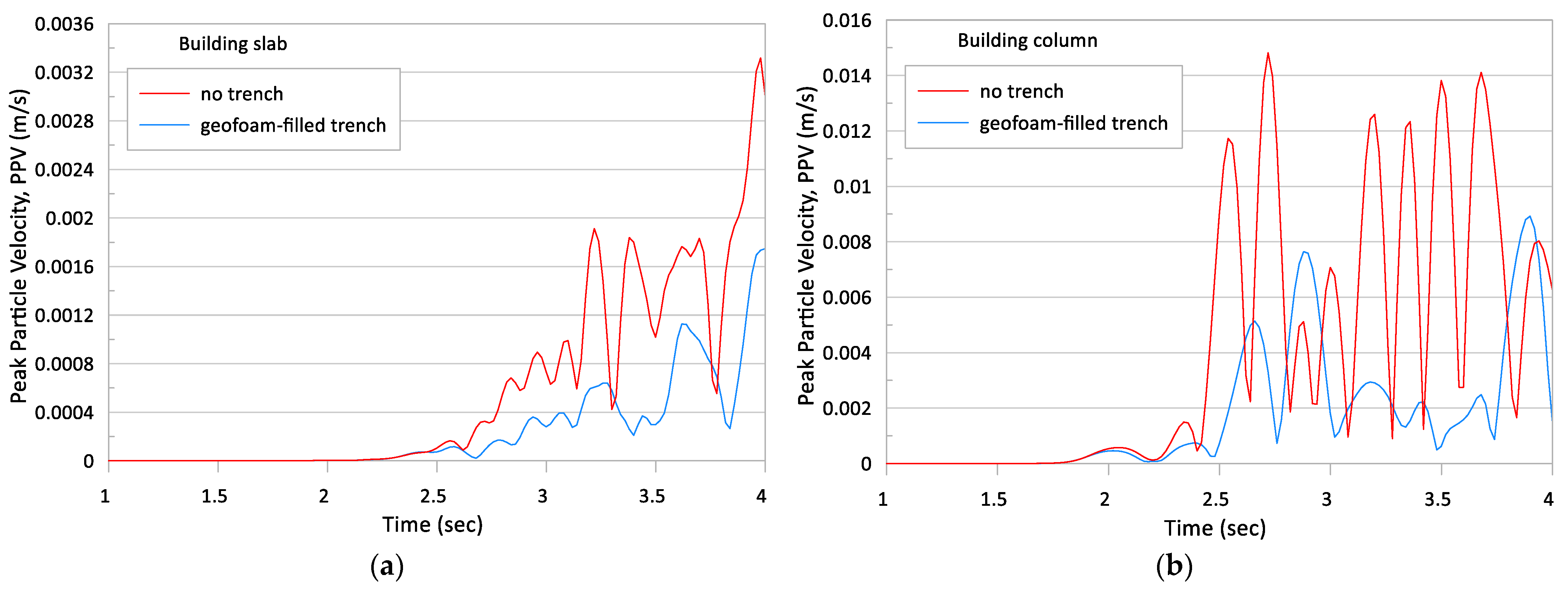
3.3. Geosynthetic-Based Ground-Borne Vibration Mitigation

Ground-borne noise and vibrations from railways in urbanized areas may cause structural disturbances and distress to the residents proximate to railway lines, requiring control and mitigation. Even in situ vibrations that fall within the safety criteria for building vibrations tend to instill fear of structural damage and building failure as humans perceive vibrations at a very small threshold (smaller than 1 mm/s) [35,36].
Ground-borne vibrations are difficult to mitigate due to their low-frequency nature [37]. Several mitigation measures are available, including meta-materials (resonator, stopband), geogrid (stiffening of subgrade), geofoam or concrete-filled trenches, and ground improvements such as concrete and stone columns (Figure 13). Geosynthetic-based solutions are gaining popularity due to their sound performance as well as sustainable benefits [38,39]. Stiffening of the subgrade beneath a railway track using layers of geogrid also has the potential to reduce the vibration level at such sites.
In this section, the performance of a geosynthetic-based mitigation method, namely a geofoam-filled trench, is demonstrated and compared to that of the no-mitigation case. A hypothetical scenario where a high-speed railway track runs with 10 m clearance along a five-story concrete framed building resting on a mat foundation was considered. A KTX-I high-speed train (HST) with a speed of 120 km/h and a maximum axle load of 170 kN (85 kN for one wheel) was run on the track. The locomotive and coach lengths were 22.7 m and 21.8 m, respectively, with a wheel diameter of 0.92 m and a wheelbase of 1.44 m. The center distance of the wheel trucks in the same car was 11 m, while that in the adjacent cars was 6.3 m. The key dimension parameters of KTX-I are given in Figure 14.
A five-story concrete framed building with a floor plan consisting of 16 columns, 600 mm × 600 m in size, evenly spaced at 4.2 m in each direction, was considered. The floor thickness was 200 mm with a height of 3.0 m. The building was supported by a 1 m thick reinforced concrete raft foundation of 14.2 m × 14.2 m. The track system consisted of (from the top) 0.4 m thick ballast, 0.2 m thick sub-ballast, and subgrade. For simplicity, a uniform layer of subgrade was assumed (Figure 14).
A three-dimensional (3D) finite element model developed using commercial finite element software, ABAQUS 2023, was adopted. The analysis was performed in a time domain using an implicit time integration scheme. The movement of axle loads was simulated in the time domain using the user subroutine DLOAD [40]. A geostatic load step was initially defined in the analyses, prior to the dynamic load step. To ensure numerical stability and to capture the initial dynamic response, a minimum time step of t m i n = 0.00275   s was used with a simulation time of 3.0   s . Considering the train speed of 120 km / h , the distance traversed by the wheel load is 100 m.
Figure 15 shows the FE model together with the dimensions. As shown, the FE model had dimensions of 100 m in length, 50 m in width, and 15 m in height. With reference to the boundary conditions, translation in the z direction was restrained on the bottom boundary, while those in the direction perpendicular to the vertical axes were restrained for lateral boundaries. In addition, the infinite nature of the ground medium was represented by placing infinite elements on the four lateral boundaries. The mesh size was selected to be 0.17 m for the rails and 0.5 m for the ballast, sub-ballast, and subgrade. All components of the FE model were discretized using eight-node hexahedral linear brick elements with reduced integration and hourglass control (C3D8R), while the 3D linear infinite element (CIN3D8) was used for the region prescribed as an infinite region. The total numbers of elements and nodes were 349,218 and 386,200, respectively.
In terms of constitutive modeling, the ballast, sub-ballast, concrete, geogrid, geofoam, and rails were considered to be linear elastic, while the subgrade was assumed to be a Mohr–Coulomb elasto-plastic material following the non-associated flow rule. The material properties are summarized in Table 2.
For the geofoam trench mitigation scenario, a 1.0 m wide, 20 m-deep, and 10 m-long trench was considered, as shown in Figure 15. The vibration levels transmitted to the building were assessed through velocity at the selected monitoring points A and B shown in Figure 15b.
The results are summarized in Figure 16, where the time histories of ground vibrations at the designated locations are illustrated in terms of peak particle velocity (PPV) for the mitigation measures considered. Note that the PPV was computed as the resultant of axial velocity components measured in the longitudinal, vertical, and lateral directions ( V l o n g , V v e r t , V l a t r ).
As shown, the geosynthetic solution, i.e., geofoam-filled trench, significantly decreases the PPV, by as much as 50% from the no-trench case. The salient feature is that high PPVs remain at the measurement points even after the passage of the train.
Although not explicitly examined, as a large portion of the carbon footprint results from the material consumption of mitigation measures, the geosynthetic solutions typically produce less carbon footprint, i.e., less than 10% of conventional approaches such as resonator, concrete-filled trench, concrete pile stiffening, etc. [41].

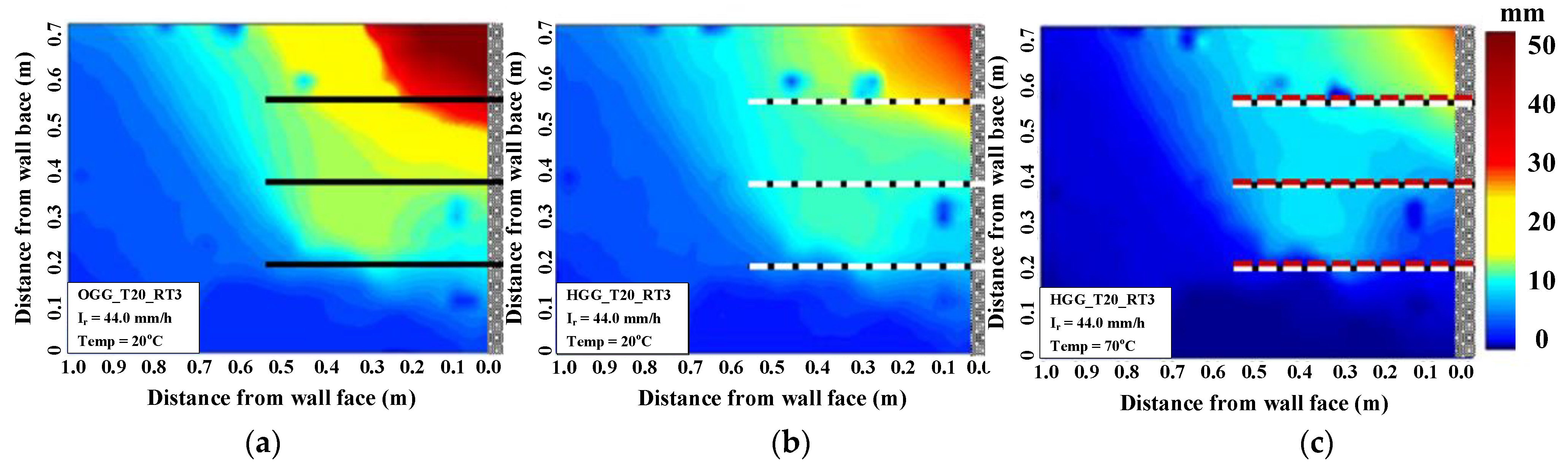
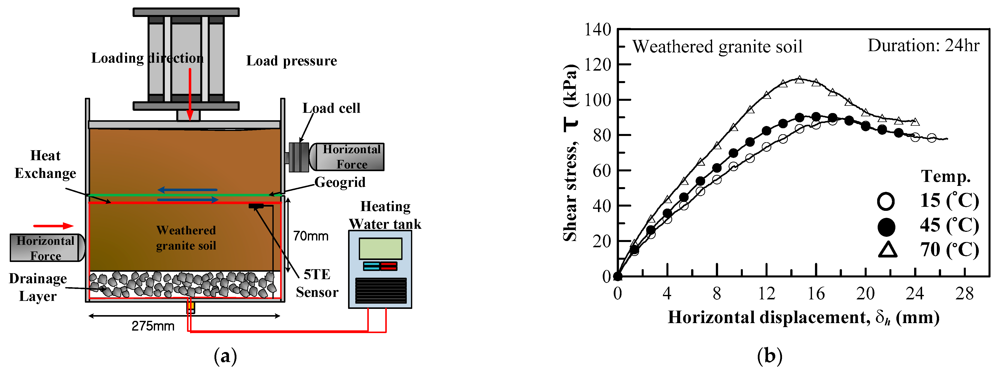
4. GRS Structure: Climate Change Adaption and Mitigation

Increased occurrence of climate change-induced heavy rainfall has raised significant concerns to geotechnical engineers in terms of the design and construction of geo-structures. Climate change-induced heavy rainfall is becoming more important as marginal soils with a high percentage of fines are frequently used as backfill due to the scarcity of high-quality fill materials and potential cost savings. This is concerning because poor-quality, marginal soils cannot readily dissipate the pore water pressure generated during rainfall, which leads to a reduction in shear strength caused by a decrease in matrix suction [42,43,44].
The positive role of in-plane drainage in relieving rainfall infiltration from GRS walls backfilled with low-quality backfill soils has been demonstrated by many researchers [43,44,45], although the capillary barrier issue remains a subject of research. More recently, a dual-function reinforcement and drainage geogrid, namely a hybrid geogrid concept, has been introduced for potential use in low-quality backfilled GRS walls [44].
As part of continuing research on this subject, a series of laboratory investigations is being conducted at SKKU to further develop climate change adaptive solutions. One of the approaches under consideration is to introduce elevated temperatures to accelerate pore water dissipation from rainwater-infiltrated soil (Figure 17). Elevated temperatures in backfill soil can facilitate water movement as the difference between the volume expansion of soil particles and water can increase pore pressure in soil [46]. Dissipation of pore water can be accelerated as the temperature increases, provided appropriate drainage measures.
The relative effects of internal drainage only and of internal drainage combined with elevated temperature are illustrated in Figure 18, where the results of laboratory tests are presented as contour plots of lateral displacement. As can be seen, a significant decrease in lateral displacement was evident when implementing in-plane drainage by the hybrid geogrid. The elevated temperature ( 70   ° C ) with the hybrid geogrid further decreased the lateral displacement, suggesting that internal drainage combined with elevated temperature (hybrid geogrid + elevated temperature) can further improve GRS wall performance in the event of heavy rainfall.
The short- and long-term effects of elevated temperature on the geogrid reinforcement and geogrid–soil interface remain to be fully investigated. A preliminary investigation on the effects of elevated temperature on the geogrid–soil interface characteristics showed no evidence of deterioration (even improvement) of the interface frictional characteristics. Further study is ongoing to confirm these findings (Figure 19).

5. Conclusions

This paper discusses the implications of climate change issues on the construction industry within the framework of sustainability. In addition, the sustainable benefits of geosynthetic solutions, as an alternative to conventional systems in infrastructure development, are briefly highlighted. Recent advances in geosynthetic solutions for transportation applications are described. The following conclusions can be drawn.
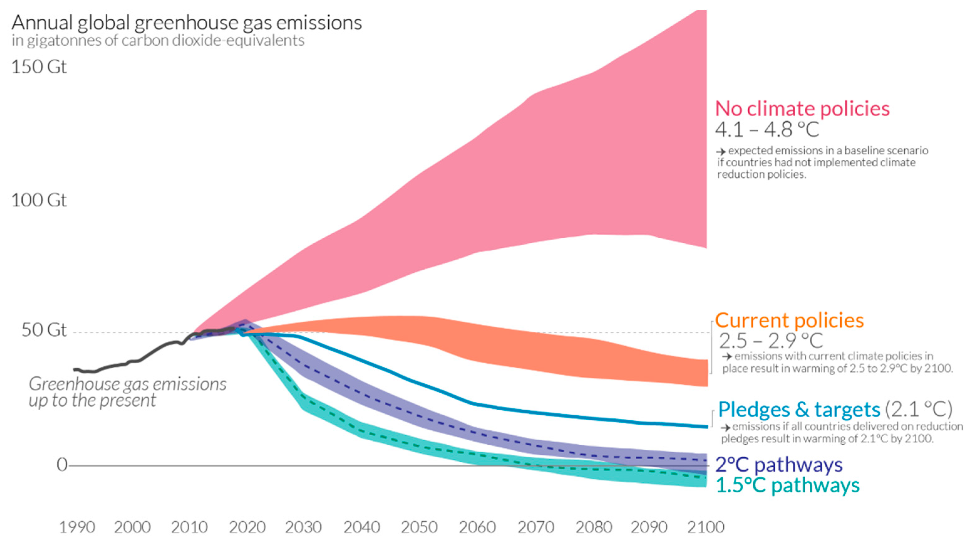
  • Climate change-induced global warming has raised global temperatures approximately 1.0 °C above pre-industrial levels, and if current rates are maintained, this will likely reach 1.5 °C between 2030 and 2052. The construction industry, as one of the larger producers of GHG emissions, has a huge responsibility to implement specific action plans to achieve sustainable construction targets.
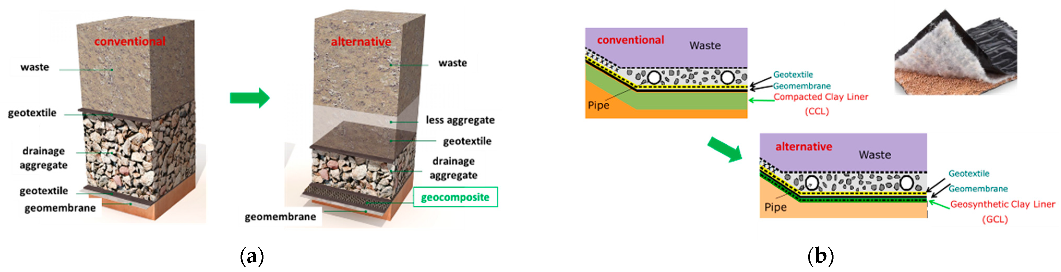
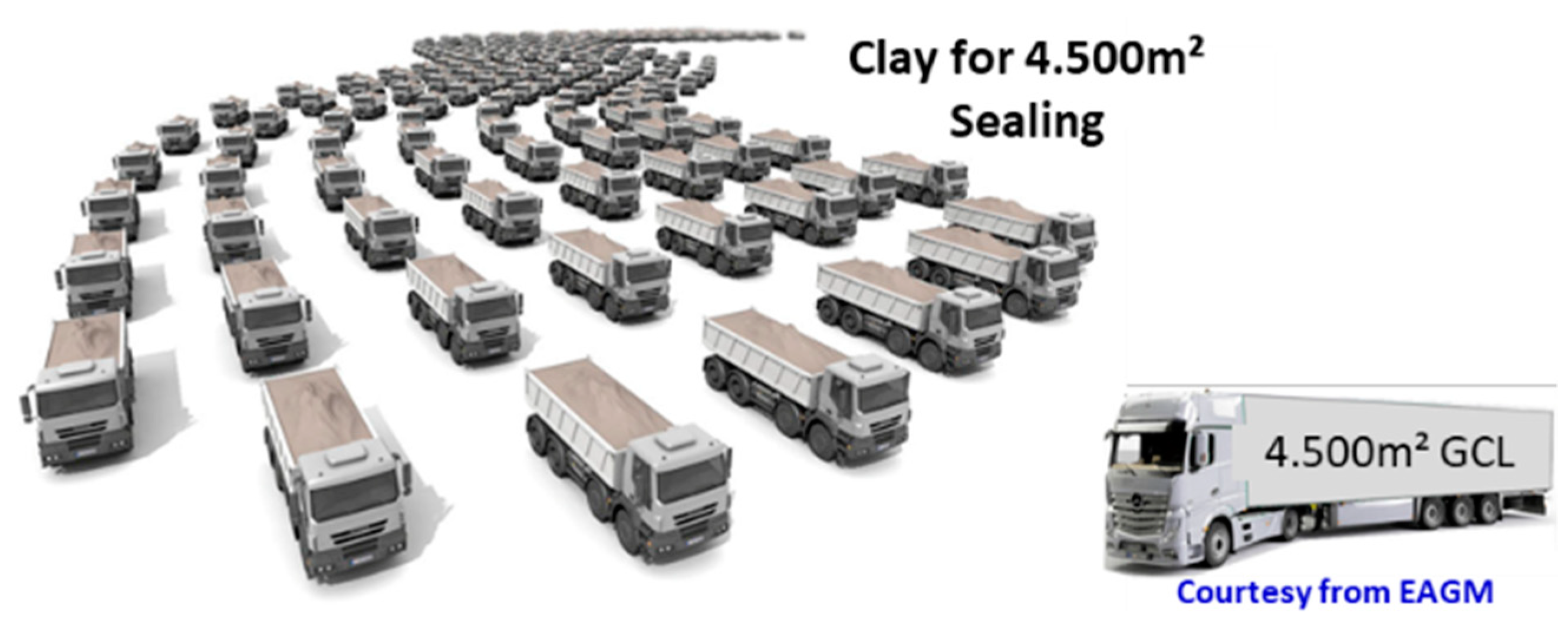
  • Geosynthetics can also be used as key elements in achieving some of the 17 UN sustainable development goals, particularly in the environmental and economic categories, including goals such as clean water and sanitation, clean energy, infrastructures, and sustainable cities. More specifically, in infrastructure development, geosynthetic solutions are considered sustainable solutions as they tend to use fewer natural resources, thus significantly reducing the carbon footprint compared to conventional systems.
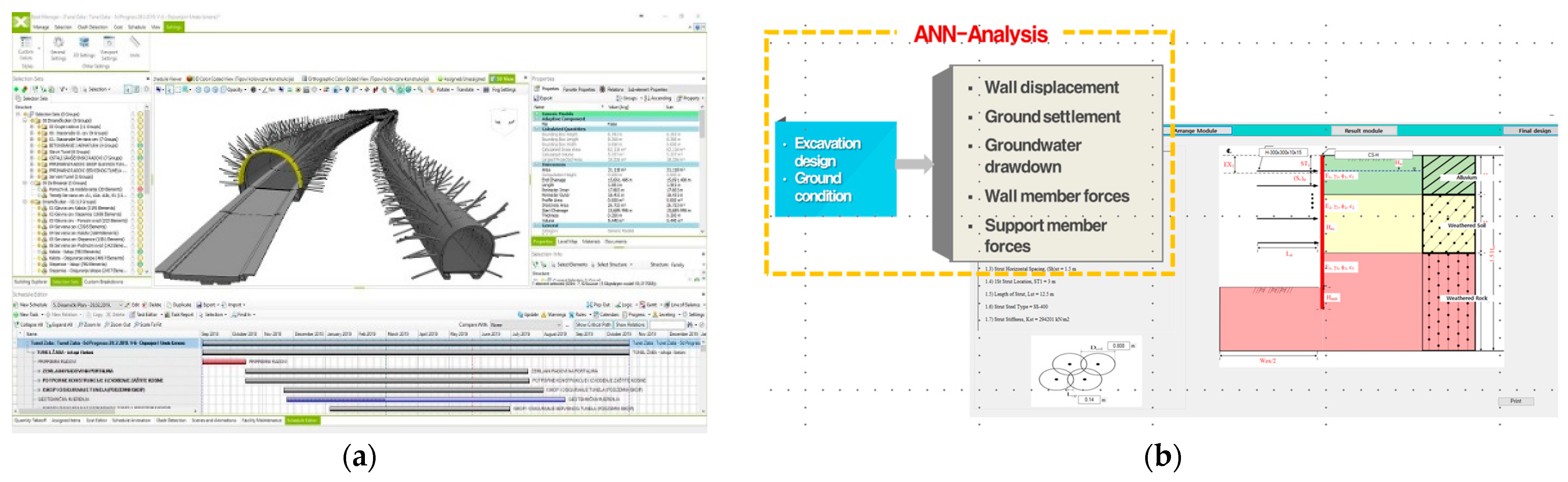
  • A wide array of geosynthetic solutions is available for infrastructure development such as geosynthetic bridge abutments, geosynthetic-encased stone columns, and geosynthetics-based ground-borne vibration mitigation. Further developments in geosynthetic technology in transportation applications will ensure safe, economical, and sustainable infrastructure development.
  • Accelerated drainage of infiltrated rainwater from a geosynthetic reinforced structure can be achieved when implementing dual-function geosynthetic, i.e., internal drainage and reinforcement, together with elevated temperature, suggesting that geosynthetic technology can provide climate change adaptation and mitigation solutions for future infrastructure development.

Funding

This research was funded by the National Research Foundation of Korea, grant numbers 2021R1A2C3011490 and 2021K2A9A1A06096050.

Data Availability Statement

The data presented in this study are available on request from the corresponding author.

Conflicts of Interest

The author declares no conflict of interest.

References

  1. Holtz, R.D. Geosynthetics for Soil Improvement, 9th ed.; Spencer, J., Ed.; Buchanan Lecture; Texas A&M University: College Station, TX, USA, 2001; pp. 1–19. [Google Scholar]
  2. Allen, M.R.O.P.; Dube, W.; Solecki, F.; Aragón-Durand, W.; Cramer, S.; Humphreys, M.; Kainuma, J.; Kala, N.; Mahowald, Y.; Mulugetta, R.; et al. Framing and Context. In Global Warming of 1.5 °C. An IPCC Special Report on the Impacts of Global Warming of 1.5 °C above Pre-Industrial Levels and Related Global Greenhouse Gas Emission Pathways, in the Context of Strengthening the Global Response to the Threat of Climate Change, Sustainable Development, and Efforts to Eradicate Poverty; Masson-Delmotte, V.P., Zhai, H.-O., Pörtner, D., Roberts, J., Skea, P.R., Shukla, A., Pirani, W., Moufouma-Okia, C., Péan, R., Pidcock, S., et al., Eds.; Cambridge University Press: Cambridge, UK; New York, NY, USA, 2018; pp. 49–92. [Google Scholar] [CrossRef]
  3. Yoo, C. Geosynthetics in Sustainable Transportation Infrastructure Construction. Keynote Lecture. In Proceedings of the 4th African Regional Conference on Geosynthetics, Cairo, Egypt, 20–23 February 2023. [Google Scholar] [CrossRef]
  4. Intergovernmental Panel on Climate Change (IPCC). IPCC Special Report on Climate Change and Land (SRCCL). In Proceedings of the Bonn Climate Change Conference, Bonn, Germany, 17–19 June 2019. [Google Scholar]
  5. European Commission. Consequences of Climate Change. Available online: https://climate.ec.europa.eu/climate-change/consequences-climate-change_en (accessed on 19 January 2023).
  6. Ritchie, H.; Roser, M.; Rosado, P. CO2 and Greenhouse Gas Emissions. 2020. Published online at OurWorldInData.org. Available online: https://ourworldindata.org/co2-and-greenhouse-gas-emissions (accessed on 19 January 2023).
  7. United Nations. The UN Sustainable Development Goals; United Nations: New York, NY, USA, 2015; Available online: http://www.un.org/sustainabledevelopment/summit/ (accessed on 16 January 2023).
  8. Raja, J.; Doxon, N.; Fowmes, G.; Frost, M.; Assinder, P. Obtaining reliable embodied carbon values for geosynthetics. Geosynth. Int. 2015, 22, 393–401. [Google Scholar] [CrossRef]
  9. Touze, N. Healing the world: A geosynthetics solution. Geosynth. Int. 2021, 28, 1–31. [Google Scholar] [CrossRef]
  10. Ramsey, B. Geosynthetics and Sustainability: How Is Our Industry Doing? Available online: https://geosyntheticsmagazine.com/2022/04/01/geosynthetics-and-sustainability/ (accessed on 19 January 2023).
  11. United Nations. 2021 Global Status Report for Buildings and Construction; United Nations: New York, NY, USA, 2021; Available online: https://www.unep.org/resources/report/2021-global-status-report-buildings-and-construction (accessed on 23 January 2023).
  12. Gourbran, S. On the Role of Construction in Achieving the SDGs. J. Sustain. Res. 2019, 1, e190020. [Google Scholar] [CrossRef]
  13. International Geosynthetics Society. Geosynthetic Barries: Applications and Benefits. 2021. Available online: https://library.geosyntheticssociety.org/wp-content/uploads/resources/educational-documents/Leaflet/IGS%20Geosynthetics%20Barriers.pdf (accessed on 30 May 2023).
  14. Raja, M.N.A.; Shukla, S.K. Predicting the settlement of geosynthetic-reinforced soil foundations using evolutionary artificial intelligence technique. Geotext. Geomembr. 2021, 49, 1280–1293. [Google Scholar] [CrossRef]
  15. Chao, Z.; Shi, D.; Fowmes, G.; Xu, X.; Yue, W.; Cui, P.; Hu, T.; Yang, C. Artificial intelligence algorithms for predicting peak shear strength of clayey soil-geomembrane interfaces and experimental validation. Geotext. Geomembr. 2023, 51, 179–198. [Google Scholar]
  16. Adams, M.; Nicks, J.; Stabile, T.; Wu, J.; Schlatter, W.; Hartmann, J. Geosynthetic Reinforced Soil Integrated Bridge System Synthesis Report; Report No. FHWA-HRT-11-027; Federal Highway Administration: Washington, DC, USA, 2011. [Google Scholar]
  17. Ahmadi, H.; Bezuijen, A. Full-scale mechanically stabilized earth (MSE) walls under strip footing load. Geotext. Geomembranes 2018, 46, 297–311. [Google Scholar] [CrossRef]
  18. Shen, P.; Han, J.; Zornberg, J.; Tanyu, B.; Christopher, B.; Leschinsky, D. Responses of geosynthetic-reinforced soil (GRS) abutments under bridge slab loading: Numerical investigation. Comp. Geotech. 2020, 123, 103566. [Google Scholar] [CrossRef]
  19. Xu, P.; Li, T.; Hatami, K. Limit analysis of bearing capacity and failure geometry of GRS bridge abutments. Comp. Geotech. 2020, 127, 103758. [Google Scholar] [CrossRef]
  20. Hatami, K.; Doger, R. Load-bearing performance of model GRS bridge abutments with different facing and reinforcement spacing configurations. Geotext. Geomembranes 2021, 49, 1139–1148. [Google Scholar] [CrossRef]
  21. Askari, M.; Razeghi, H.R.; Mamaghanian, J. Numerical study of geosynthetic reinforced soil bridge abutment performance under static and seismic loading considering effects of bridge deck. Geotext. Geomembr. 2021, 49, 1339–1354. [Google Scholar] [CrossRef]
  22. Deng, J.; Zhang, J.; Qi, Z.; Zheng, Y.; Zheng, J.J. Experimental study on the load bearing behavior of geosynthetic reinforced soil bridge abutments on yielding foundation. Geotext. Geomembr. 2023, 51, 165–178. [Google Scholar] [CrossRef]
  23. Verma, A.; Mittal, S. Comparative assessment of stability of GRS abutments through 1 g physical model tests for field implementationeck. Trans. Geotech. 2023, 42, 101056. [Google Scholar] [CrossRef]
  24. Yoo, C.; Kim, S.B. Performance of a two-tier geosynthetic reinforced segmental retaining wall under a surcharge load: Full-scale load test and 3D finite element analysis. Geotext. Geomembr. 2008, 26, 460–472. [Google Scholar] [CrossRef]
  25. Yoo, C.; Lee, D. Performance of geogrid-encased stone columns in soft ground: Full-scale load test. Geosynth. Int. 2012, 19, 480–490. [Google Scholar] [CrossRef]
  26. Yoo, C. Performance of geosynthetic-encased stone columns in embankment construction: Numerical investigation. J. Geotech. Geoenviron. 2010, 136, 1148–1160. [Google Scholar] [CrossRef]
  27. Yoo, C.; Abbas, Q. Laboratory investigation of the behavior of a geosynthetic encased stone column in sand under cyclic loading. Geotext. Geomembr. 2020, 48, 431–442. [Google Scholar] [CrossRef]
  28. Almeida, M.S.S.; Hosseinpour, I.; Riccio, M. Performance of a geosynthetic-encased column (GEC) in soft ground: Numerical and analytical studies. Geosynth. Int. 2013, 20, 252–262. [Google Scholar] [CrossRef]
  29. Almeida, M.S.S.; Hosseinpour, I.; Riccio, M.; Alexiew, D. Behavior of geotextile–encased granular columns supporting test embankment on soft deposit. J. Geotech. Geoenviron. 2014, 141, 1–9. [Google Scholar] [CrossRef]
  30. Ali, K.; Shahu, J.T.; Sharma, K.G. Model tests on single and groups of stone columns with different geosynthetic reinforcement arrangement. Geosynth. Int. 2014, 21, 103–118. [Google Scholar]
  31. Cengiz, C.; Güler, E. Seismic behavior of geosynthetic encased columns and ordinary stone columns. Geotext. Geomembr. 2018, 46, 40–51. [Google Scholar] [CrossRef]
  32. Alkhorshid, N.R.; Araujo, L.S.; Palmeira, E.M.; Zornberg, J.G. Large-scale load capacity tests on a geosynthetic encased column. Geotext. Geomembr. 2019, 47, 631–642. [Google Scholar] [CrossRef]
  33. Xu, Z.; Zhang, L.; Peng, B.; Zhou, S. DEM-FDM numerical investigation on load transfer mechanism of GESC-supported embankment. Comp. Geotech. 2021, 138, 104321. [Google Scholar] [CrossRef]
  34. Zhou, Y.; Kong, G.; Zheng, J.; Wen, L.; Yang, Q. Analytical solutions for geosynthetic-encased stone column-supported embankments with emphasis on nonlinear behaviours of columns. Geotext. Geomembr. 2021, 49, 1107–1116. [Google Scholar] [CrossRef]
  35. Amick, H.; Gendreau, M. Construction vibrations and their impact on vibration-sensitive facilities. In Proceedings of the 6th Construction Congress, ASCE, Orlando, FL, USA, 20–22 February 2000; pp. 758–767. [Google Scholar] [CrossRef]
  36. Rainer, J.H. Effect of vibrations on historic buildings: An overview. Bull. Assoc. Preserv. Technol. 1982, 14, 2–10. [Google Scholar]
  37. Khan, M.R.; Dasaka, S.M. High-Speed Train Vibrations in the Sub-soils Supporting Ballasted Rail Corridors. Transp. Infrastruct. Geotech. 2022, 10, 259–282. [Google Scholar] [CrossRef]
  38. Majumder, M.; Bhattacharyya, S. ANN-Based Model to Predict the Screening Efficiency of EPS Geofoam Filled Trench in Reducing High-Speed Train-Induced Vibration. In Seismic Hazards and Risk; Springer: Singapore, 2021. [Google Scholar] [CrossRef]
  39. Liu, W.; Yan, S.; Wu, L.; Zhou, J. Metamaterial approach to mitigate ground-borne vibrations induced by moving trains. Appl. Res. 2022, 2, e202200021. [Google Scholar] [CrossRef]
  40. Dassault Systems; ABAQUS, Hibbit, Karlsson Sorensen Inc.: Providence, RI, USA, 2022.
  41. Kaewunruen, S.; Qin, Z. Sustainability of Vibration Mitigation Methods Using Meta-Materials/Structures along Railway Corridors Exposed to Adverse Weather Conditions. Sustainability 2020, 12, 10236. [Google Scholar] [CrossRef]
  42. Koerner, R.M.; Soong, T.Y. Geosynthetic reinforced segmental retaining walls. Geotext. Geomembr. 2001, 19, 359–386. [Google Scholar] [CrossRef]
  43. Yoo, C.; Jung, H.Y. Case history of geosynthetics reinforced segmental retaining wall failure. J. Geotech. Geoenviron. 2006, 132, 1538–1548. [Google Scholar] [CrossRef]
  44. Yoo, C.; Tabish, A.; Yang, J.W.; Abbas, Q.; Song, J.S. Effect of internal drainage on deformation behavior of GRS wall during rainfall. Geosynth. Int. 2022, 29, 137–150. [Google Scholar] [CrossRef]
  45. Portelinha, F.H.; Zornberg, J.G. Effect of infiltration on the performance of an unsaturated geotextile reinforced soil wall. Geotext. Geomembr. 2017, 45, 211–226. [Google Scholar] [CrossRef]
  46. McCartney, J.S.; LaHaise, D.; LaHaise, T.; Rosenberg, J. Application of Geoexchange Experience to Geothermal Foundations. In Proceedings of the Art of Foundation Engineering Practice Congress 2010, West Palm Beach, FL, USA, 20 February 2010. [Google Scholar] [CrossRef]
Figure 1. Human experience of present-day warming [2].
Sustainability 15 15772 g001
Figure 2. Global GHG emissions scenarios [6].
Sustainability 15 15772 g002
Figure 3. The 17 UN Sustainable Development Goals (SDGs) (from https://www.un.org/sustainabledevelopment/news/communications-material/ (accessed on 1 February 2023)).
Sustainability 15 15772 g003
Figure 4. Sustainable benefits of geosynthetics: (a) geocomposites as a drainage layer and (b) geosynthetic clay liner as a barrier.
Sustainability 15 15772 g004
Figure 5. Illustration of fewer truckloads required for a site when geosynthetic materials are used, compared to the traditional solution.
Sustainability 15 15772 g005
Figure 6. Digital tools for sustainable construction design: (a) BIM in tunnel design (https://www.bimcommunity.com/news/load/1136/parametric-bim-tunnel-design (accessed on 1 February 2023)) and (b) deep-learning-based design.
Sustainability 15 15772 g006
Figure 7. Typical cross-section of a GRS abutment Adapted with permission from Ref. [17]. 2021, “Geotext. Geomembr.”.
Sustainability 15 15772 g007
Figure 8. Full-scale test wall configuration and results: (a) test wall configuration, (b) facing displacement, and (c) reinforcement strains Adapted with permission from Ref. [18]. 2008, “Geotext. Geomembr.”.
Sustainability 15 15772 g008
Figure 9. Illustration of the GESC technique: (a) schematic view and (b) installation procedure [3].
Sustainability 15 15772 g009
Figure 10. Full-scale load test on OSC and GESC Adapted with permission from Ref. [25]. 2012, “Geosynth. Int.”: (a) test setup, (b) lateral displacement, and (c) load vs. settlement.
Sustainability 15 15772 g010
Figure 11. Settlement characteristics of a GESC-supported embankment Adapted with permission from Ref. [26]. 2010, “J. Geotech. Geoenviron.”: (a) GESC-supported embankment, (b) excess pore pressure dissipation, and (c) settlement development.
Sustainability 15 15772 g011
Figure 12. Response characteristics of a GESC-supported embankment to cyclic loading Adapted with permission from Ref. [27]. 2020, “Geotext. Geomembr.”: (a) settlement ratio, (b) excess pore pressure, and (c) settlement improvement ratio.
Sustainability 15 15772 g012
Figure 13. Typical train-induced ground-borne vibration mitigations [39,40].
Sustainability 15 15772 g013
Figure 14. Configuration of the high-speed train (HST) considered (KTX-I, axle load ≤ 17 t).
Sustainability 15 15772 g014
Figure 15. Finite element model: (a) entire model and (b) cross-section.
Sustainability 15 15772 g015
Figure 16. Time history of PPV for different migration measures at selected measurement points: (a) floor (Point A) and (b) column (Point B).
Sustainability 15 15772 g016
Figure 17. Concept of accelerated internal drainage using elevated temperatures in a GRS wall.
Sustainability 15 15772 g017
Figure 18. Contour plots of lateral displacement: (a) no internal drainage (ordinary geogrid), (b) with internal drainage (hybrid geogrid), and (c) with internal drainage + elevated temperature (hybrid geogrid + elevated temperature).
Sustainability 15 15772 g018
Figure 19. Effect of elevated interface temperature on the geosynthetics–soil interface: (a) test setup and (b) shear stress–displacement relationship.
Sustainability 15 15772 g019
Table 1. Test cases considered [Adapted with permission from Ref. [27]. 2010, “J. Geotech. Geoenviron.”].
Series s u   ( kPa ) Frequency,
f   ( Hz )
Amplitude,   A m   ( kPa ) No. of Cycles,
N
Encasement Length,   L e n c / H
A120.1, 0.5, 1.07010,8001.0
B0.540, 70, 1001.0
C0.5700.0, 0.3, 0.5, 1.0
Table 2. Material properties used in the FE analysis.
MaterialUnit Weight γ   ( kN m 3 ) Young’s Modulus E   ( M P a ) Poisson’s Ratio, ν Cohesion, c   ( k P a ) Int. Friction Angle,   ϕ ( ° ) Dilation Angle,   ψ ( ° )
ballast16150.35---
sub-ballast1920000.35---
subgrade20410.4104015
concrete2521,0000.2---
rail78.5200,0000.35---
geofoam2015000.49---
Disclaimer/Publisher’s Note: The statements, opinions and data contained in all publications are solely those of the individual author(s) and contributor(s) and not of MDPI and/or the editor(s). MDPI and/or the editor(s) disclaim responsibility for any injury to people or property resulting from any ideas, methods, instructions or products referred to in the content.

