Review

Evolution of Geocells as Sustainable Support to Transportation Infrastructure

Department of Civil Engineering, Indian Institute of Science, Bangalore 560012, India
*
Author to whom correspondence should be addressed.
Sustainability 2023, 15(15), 11773; https://doi.org/10.3390/su151511773
Submission received: 2 June 2023 / Revised: 18 July 2023 / Accepted: 21 July 2023 / Published: 31 July 2023
(This article belongs to the Special Issue Sustainability and Innovation in Transport Infrastructure Geotechnics)

Abstract

:
Geocells, which are polymeric interconnected cells filled with soil, provide excellent support to loads through all-round confinement and a beam effect; hence, they are extensively used in various geotechnical applications such as embankments, foundations, pavements, slopes, railways, and reinforced earth (RE) walls. Although the applications of geocells are studied extensively, their geometric and parametric evolution as a stable support to heavy loads receive less attention. The current versatile configuration of geocells has geometrically evolved after accounting for all the factors that give them optimum reinforcement efficiency. This paper presents a state-of-the-art review of the geometric evolution of geocells in the context of transportation geotechnical engineering. Effects of shape, size, stiffness, and surface roughness of geocells, and properties of infill and native soils on the performance of geocells are compiled from the literature to get important design insights. The application of geocells in pavements is discussed, concluding that geocells improve the cyclic load carrying capacity and resilient characteristics of pavement, reduce rut depths, and increase traffic benefit ratio (TBR). Hence, geocells can be a sustainable alternative to natural materials in transportation infrastructure, with the added advantages of reduced carbon footprint and maintenance costs.

1. Introduction

Since the 1970s, geocells are being widely used in various applications of geotechnical engineering. The idea of a cellular confinement system was originally developed by US army corps of engineers for the ease of transport of military vehicles over weak subgrades [1]. The first cellular confinement systems were made of paper, which were later replaced by aluminum and wooden cells [2,3]. An early version of geocells, which were called sandgrids made of plastic or aluminum used by US Waterways Experimentation Station at Vicksburg, MS, USA in 1979, as illustrated by Webster [1], is shown in Figure 1.
The modern form of geocells came into existence since 1980s. Unlike planar textiles and grids, geocells, which are three-dimensional networks of cells filled with a choice of soil, provide added benefits such as all-round confinement through hoop stresses developed in the cells and a beam effect resulting from their stiff-mat configuration. Geocells, by virtue of their shape and depth, provide greater load-bearing capacity and reduce lateral deformations in soils confined by them under static and cyclic loading scenarios [4,5,6,7]. The inclusion of geocells in various structures has additional benefits such as stability improvement, climate resilience, higher resistance to cyclic loads, erosion control, basal support, and savings in time and cost [4,8]. Because of these merits, geocells are extensively used in pavements, slopes, foundations, embankments, and reinforced earth (RE) walls. Recently, geocells have also found application in heavy-duty highways and high-speed trains [5,6].
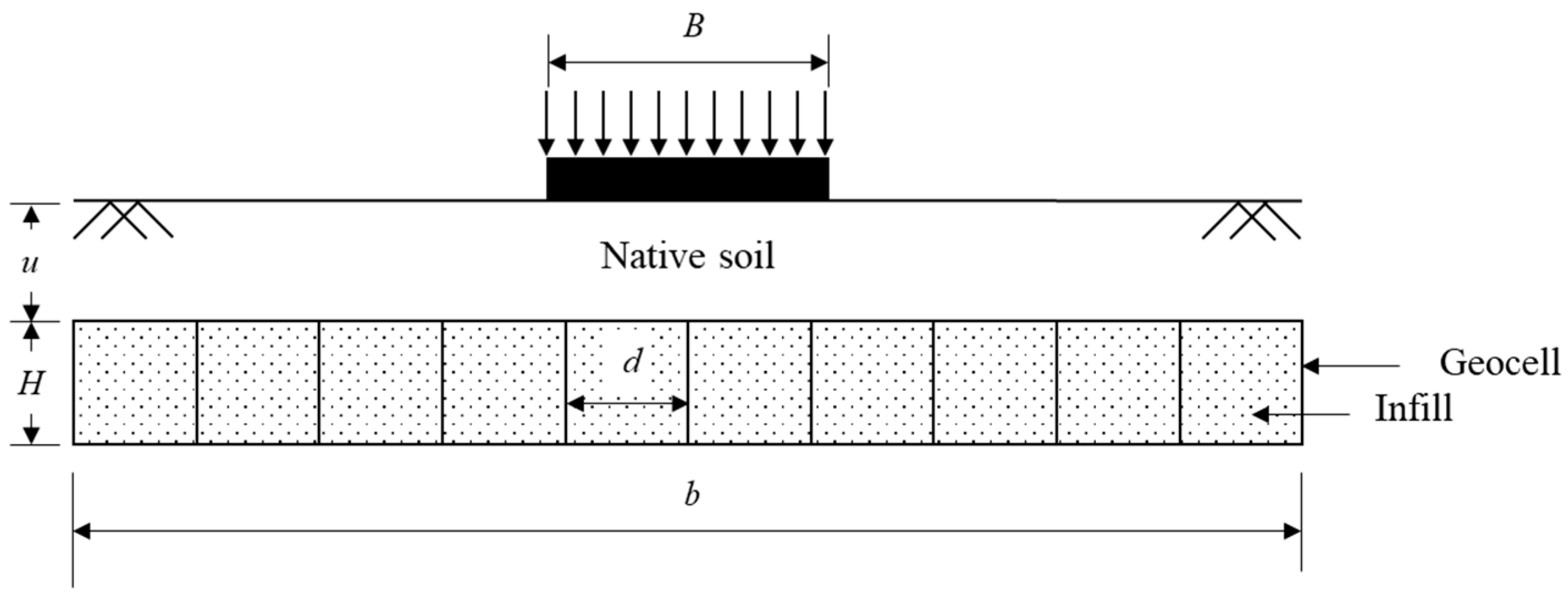
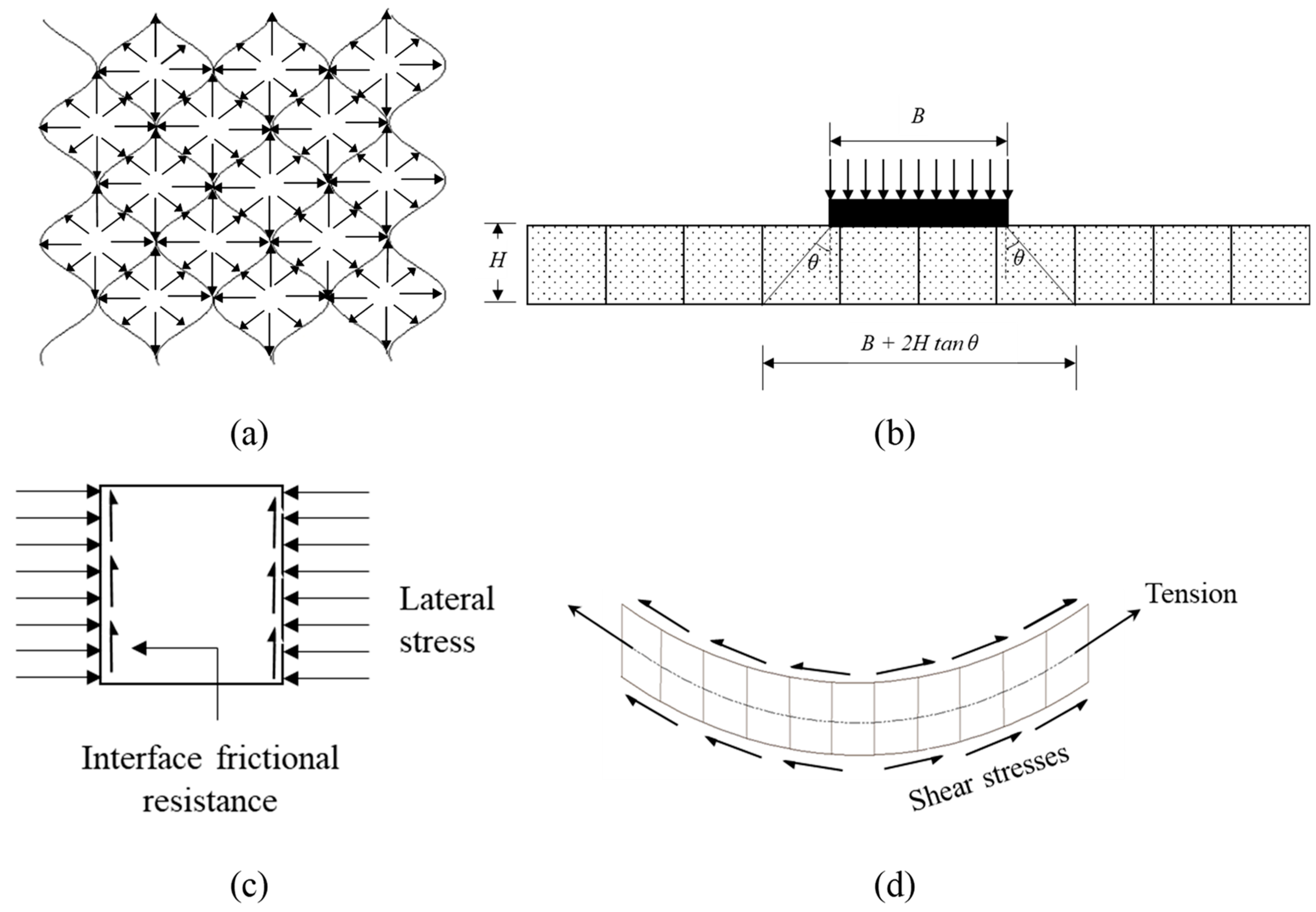
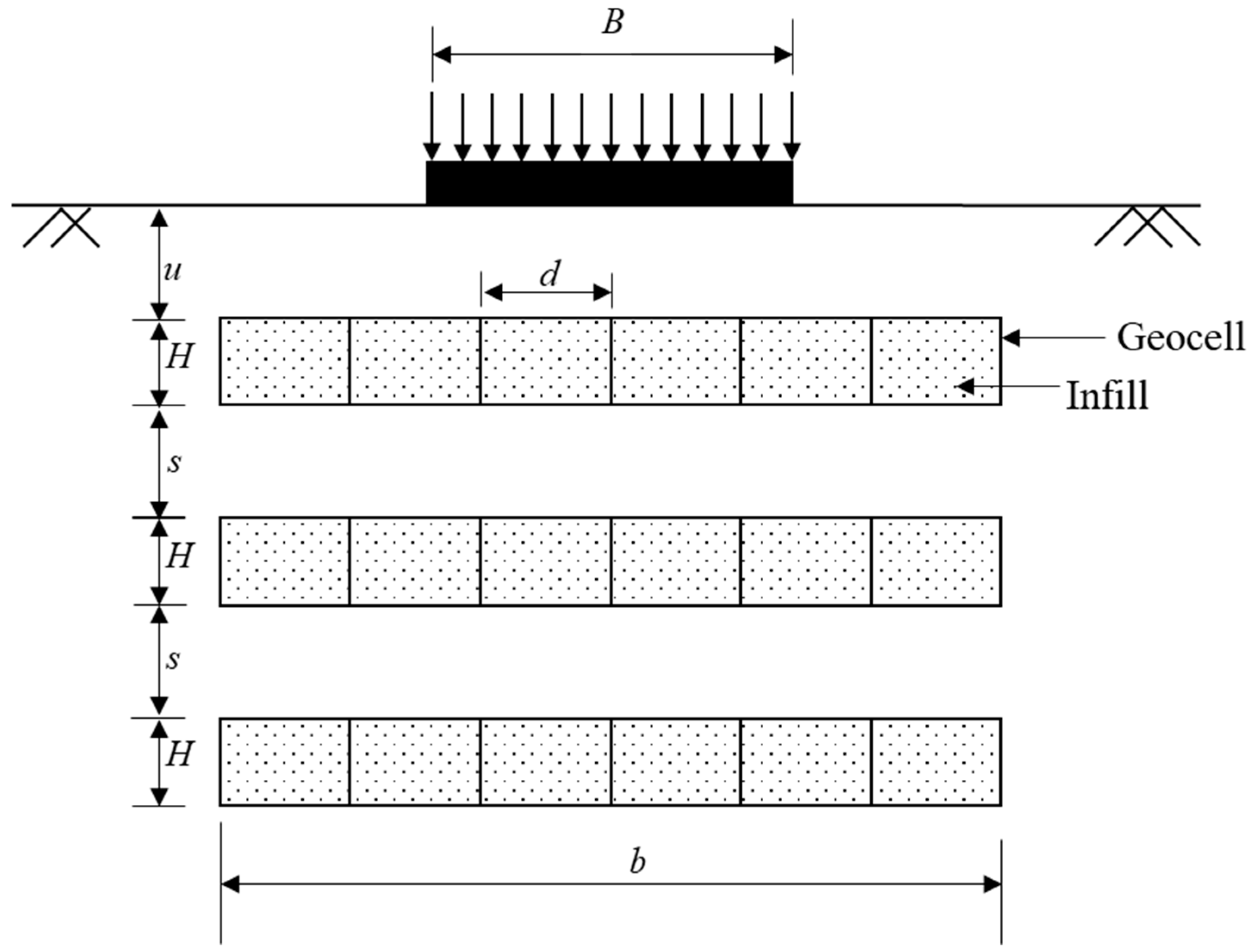
The mechanism of geocell reinforcement has been investigated by many researchers through experimental, numerical, and analytical studies. In a network of geocells, each cell is surrounded by several neighboring cells, and all the cells are filled with soil. With the application of external load, the soil inside the geocell pushes the cell wall, resulting in the development of an additional confining stress along the wall [4,8,9,10]. The additional confinement is translated into apparent cohesion, thereby increasing the shear strength of the soil, and preventing its lateral spread [11]. Furthermore, the extension of cell walls is opposed by the lateral stresses from the neighboring cells, causing the interconnected network of geocells to act as a cushion or stiffened mattress with higher strength and stiffness. This beam action redistributes the externally applied loads over a wider area and, thus, reduces the magnitude of stresses acting on the underlying soil [12]. This stiffened soil–geocell composite also hinders the propagation of the failure surface into the underlying soil [13]. Furthermore, at large displacements, the geocell layer acts as a tensioned membrane, providing sufficient upward resistance to the applied loads and, thus, reducing the stresses on the underlying soil [12,14]. A schematic representation of a geocell-reinforced soil bed is shown in Figure 2. In this figure, B represents the width of the foundation, u represents the depth of the geocell layer from the ground surface, and H, d, and b represent the height, pocket size, and width of the geocell layer, respectively. Various mechanisms responsible for the reinforcing action of geocells are presented in Figure 3. In this figure, θ represents the angle of load dispersion.
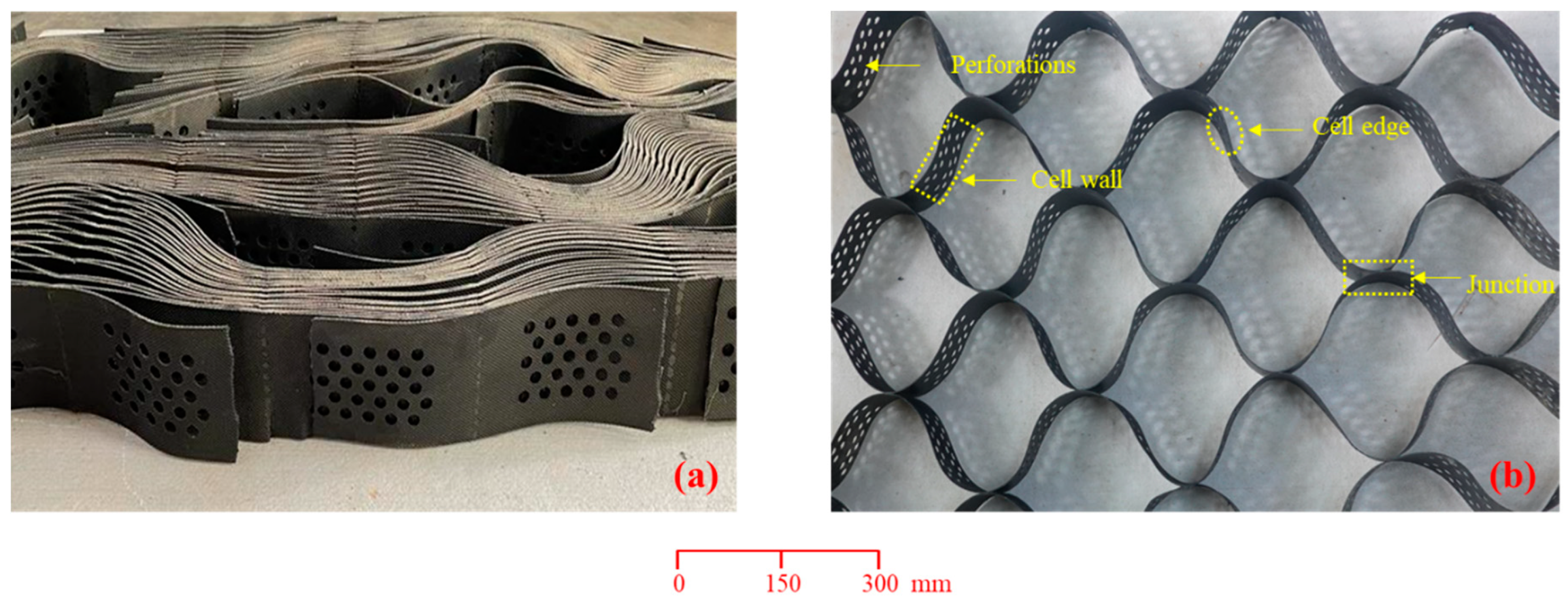
Figure 4 shows a photograph of the latest form of commercially available honeycomb-shaped geocells available at the Indian Institute of Science, Bangalore. Figure 4a shows the collapsed form of geocells, which helps in stacking large volumes of geocells in a compact form. In Figure 4b, an expanded form of a geocell layer is shown, and the cell wall, junctions, and perforations are marked. Geocells took almost five decades to evolve geometrically to their current versatile configuration. Historically, geocell layers were fabricated onsite using planar geosynthetics such as geotextiles and geogrids by strategically connecting the cells and filling them with granular soils [15]. Initially, resins and additives were used to connect the cells, which were chronologically replaced by bodkin joints, photo lamination, and ultrasonic welding in the most recent form of commercial geocells. Similarly, the geometric shape of the geocells has also undergone several transformations from square, circular, rectangular, diamond, and hexagonal to honeycomb. Furthermore, the cell material also evolved from paper, aluminum, and wood to polymer [3]. Currently, solid or perforated high-density polyethylene (HDPE) and novel polymeric alloy (NPA) are the commonly used polymers to manufacture geocells. However, the latter is more popular due to its greater flexibility, thermo-plasticity, and surface texture [16].
The present-day configuration of honeycomb geocells enables them to enclose maximum infill with a minimum perimeter of cells [8]. While manufacturing geocells, surface texture is imparted to the geocells, as shown in Figure 4, to enable them to mobilize greater interfacial shear strength when they are in contact with soils [17]. The postmortem analysis of geocells from various model tests showed that the junctions of the geocells remained intact even when local straining and buckling were observed in geocell walls [18,19]. Furthermore, the perforations present on the geocell walls (refer to Figure 4) facilitate easy drainage to dissipate pore pressures that develop inside the cells. These perforations also provide adequate interlocking between infill soils of adjacent geocells so that the geocell-reinforced soil behaves like a stiffened composite mass [20]. The perforations on cell walls also facilitate root growth within the cells, which is beneficial when vegetation is grown on geocell walls and slopes. The total pore area of the perforations is typically 6–22% of the unit area of the geocell wall. Table 1 presents the typical range of geometric and mechanical properties of commercial geocells reported by earlier studies [8,16] and geocell manufacturing companies.
This paper presents a comprehensive review of the evolution of geocells as a strong ground reinforcement technique. The objective is to provide new perspectives on the evolution of geocell reinforcement. Since no review paper is available on the geometric and parametric evolution of geocells, these perspectives are important for choosing the right geocells for a specific application and to create better geocells for futuristic applications.

2. Geocell Configuration

The reinforcement efficiency of geocells is mainly governed by the geocell configuration, geocell material properties, and soil properties. This section presents a detailed discussion on the evolution of geocells with variations in the parameters grouped under these three categories. Various studies that dealt with the variation in geocell geometry and configuration are reviewed, and the individual and combined effects of these parameters are discussed in light of the published papers. The geocell configuration mainly pertains to the shape, size, quantity, and location of geocells. The various factors that define the configuration are the height (H), overall width (b), pocket shape, and pocket opening size (d), which is the diameter of the equivalent circle, the pattern of arrangement in the case of geocells made of geogrids, embedment depth (u), and the number of geocell layers, as depicted in Figure 2. Since geocells improve strength through friction and interlocking, their height, width, and pocket size play a pivotal role in their reinforcing action. The number of geocell layers (N) becomes an important parameter only at higher levels of external loads applied on weak soils.

2.1. Height of the Geocells (H)

Several studies are available in the literature on the influence of the height of geocells on their performance. In all these studies, the performance of the geocell-reinforced structures improved with an increase in the height of the geocells up to an optimum value; thereafter, it either stabilized or declined. As height increases, the surface area of geocells increases, and the frictional resistance also increases, which helps in arresting the downward movement of the soil [16,21]. Furthermore, the increase in the height of the geocells enables the geocell-reinforced soil to act as a composite body, providing anchorage, as shown in Figure 2. It also increases the bending and shear rigidity of geocell-reinforced structures due to an increase in the moment of inertia, which redistributes the overlying load to a larger area, resulting in enhanced load-carrying capacity and reduced settlements in the underlying soil [17,22,23,24,25]. The increased rigidity offered by the geocell-reinforced soil composite from the increased height of the geocells provides adequate confinement to the infill soil, which prevents lateral displacements [23,24,26,27]. Moreover, the interlocking resistance at the soil–geocell interface increases with the height of the geocells, which effectively resists the downward drag developed during the application of external loads [18,24]. However, after a certain height, local buckling and straining of geocell walls immobilize the increment in flexural and shear rigidity of the geocells; thus, the loads are not effectively transferred through the geocell layer, leading to a deterioration in performance [23,24,25,28,29,30]. Furthermore, the height of geocells beyond the pressure bulb below the foundation can be considered dormant [31]. The optimum depth of geocells is always less than twice the width of the footing, as validated in most of the available studies [17,18,24,27,32,33]. Additionally, the increasing height of geocells poses problems related to compaction in the field, reducing the density of the infill soil [27,31].
Studies showed that geocells with smaller heights usually behave as flexural members, and that, with an increase in height, they exhibit deep beam behavior [13,34]. The tensile strength mobilized through the membrane action of geocells also adds to the improvement in performance with an increase in the height of geocells [28]. For a relatively smaller height of the geocells, linear variation of strains was observed along the depth of the geocells, resulting in maximum strain at the bottom. However, for larger heights, the maximum strain was observed at the top and decreased toward the bottom of the geocell mattress, as observed by Dash et al. [13] in plate load tests. This behavior is analogous to the variation of flexural strains along the depth of shallow and deep beams. A geocell layer of smaller height behaved as a centrally loaded thin beam under loads with compressive strains at the top and tensile strains at the bottom [35]. However, with an increase in depth, the tensile strains increase and propagate throughout the depth of the geocells. Thus, the frictional and passive resistance derived from the deep beam behavior of taller geocells was sufficient enough to hold them against the downward drag of the load and, hence, reduced the magnitude of stresses transmitted to the underlying soil [35]. These observations agree with the studies of Cheung and Chan [36] on concrete beams with different span-to-depth ratios.
The observations on the performance of geocells with varying heights are also applicable to cyclic loading. Studies on geocell-reinforced pavements showed that the cumulative permanent deformations (CPD) decreased with an increase in the height of the geocells. For shorter geocells, the flexural stiffness was relatively smaller, resulting in greater CPDs, whereas taller geocells provided enough structural support to restrain the CPDs. This also enhanced the resilient characteristics of the geocells, resulting in greater traffic benefit ratio [37].

2.2. Pocket Size or Aperture Opening Size (d)

Since the pocket size of the geocells is inversely proportional to the confining stresses developed in the infill soil, the decrease in the pocket size of geocells increases the additional confining stresses offered by the cells per unit volume of the soil, increasing the apparent cohesion [8,27,35,38]. Thus, the infill soil gets restrained within the geocell pockets due to increased confining stress, leading to controlled settlements and heaves in geocell-reinforced structures [7,22,27]. While it is intuitive to think that a decrease in pocket size results in an overall improvement in the performance of geocells due to a higher reinforcement effect, the literature shows that these correlations are not always true. The performance of geocell-reinforced structures improves with the decrease in the pocket size of geocells up to a certain optimum value and then stabilizes or declines thereafter. Furthermore, the decrease in the pocket size of geocells increases their surface area, which increases the active lateral pressure developed within the geocell wall, thereby enhancing the overall rigidity offered by the geocell reinforced soil composite [28,39]. However, beyond a certain value, the improvement in performance is negligible. A decrease in the pocket size develops a large amount of counteracting membrane stresses along the geocell walls, resulting in their local buckling and straining, which in turn reduces the flexural and shear rigidity offered by the geocells [13]. Additionally, decreasing the pocket size of geocells poses practical problems for compaction in the field.

2.3. Aspect Ratio of Geocells (H/d)

The aspect ratio of geocells is defined as the height ratio of the geocells to their pocket size. Since the aspect ratio of geocells can be varied by altering either the height of the geocells or their pocket size, the effects of the height and pocket size of geocells described in previous sections can also be viewed through the lens of a change in aspect ratio. Even though many studies are available on the effects of height and pocket size of geocells on their performance, studies specific to aspect ratio are rare [22,40].
The performance of a geocell-reinforced bed, in general, improves with an increase in the height or a decrease in the pocket size of geocells, as discussed earlier. However, this does not imply that increasing the aspect ratio continuously improves the performance of geocells. The literature presents strikingly contrasting observations regarding the optimum value of aspect ratio. While plate load tests on foundations carried out by Dash et al. [22] suggested that the optimum aspect ratio of geocells is 1.67, results from embankment model studies of Krishnaswamy et al. [40] showed that the optimum aspect ratio is close to unity. The optimum aspect ratio is seen to be a function of geocell configuration, geocell type, foundation properties, and loading [22].

2.4. Width of Geocell Layer (b)

Stresses in soils due to imposed loads on the ground are not just vertically below the load; they follow specific distribution that extends beyond the loaded area. Hence, the reinforcement provided in the soil must at least cover the stressed soil zone and ideally project a little beyond the stressed zone to have adequate anchorage and bonding. Geocell reinforcement layers are usually provided to widths (b) extending beyond the loaded area. The literature suggests that the performance of geocell-reinforced structures increases with the increase in the width of the geocell layer until a certain optimum value, beyond which the effects are negligible. The increase in the width of the geocells increases the rigidity offered by the geocells through the end bearing resistance derived from the enhanced confinement of geocell infill soil composite. Hence, the load is distributed over a larger area of the underlying soil [18,23,39]. This is one of the much-valued benefits of geocell reinforcement because the zone of influence of the load gets truncated slightly below the geocell layer, unlike in the case of the unreinforced soil, where it extends to about twice the width of the loaded area. Furthermore, wider geocell layers have higher quantities of cells contributing to the reinforcement effect, which is another reason for the improved performance [32]. Wider geocells result in less propagation of the failure wedge into the underlying soil and, hence, less surface heaving [22,23,28,39]. However, large widths induce local buckling and straining of geocell walls, which dampen the effects of flexural and shear rigidity of the geocells [23]. Analysis of the exhumed geocells after load tests showed higher strains and buckling-type deformations predominantly in the regions under and around the loaded area [23], while the portions of geocell mattress that are far from the load remained intact [13]. Extending geocells beyond the influence zone of footings is beneficial to derive secondary anchorage via frictional and passive resistance at the soil–geocell interface [22,25,39].
In a geocell mattress below a foundation, the maximum tensile strain developed at the center of the footing, and the strains in the geocells reduce rapidly with the increase in the radial distance from the center of the footing. Furthermore, compressive strains were observed to develop at both edges if the width of the geocell mattress was relatively large compared to the width of the footing [13]. When the width was lower, the geocell mattress behaved like a slender column in which the load transfer mechanism was similar to that of a pile. With an increase in the width, it behaved like a composite beam, redistributing the footing load over a larger area [7]. As observed from several studies, the optimum width ratio, which is defined as the ratio of the width of the geocell layer (b) to the width of the footing (B), must be between 4 and 5 to derive maximum improvement in load-bearing performance. This range seems to be logical, considering that the zone of influence of a footing can extend up to twice its width on either side of its central line. Providing layer widths beyond 5B is not beneficial, as asserted by several researchers [7,22,25,28,30,39,40].

2.5. Pocket Shape of the Geocells

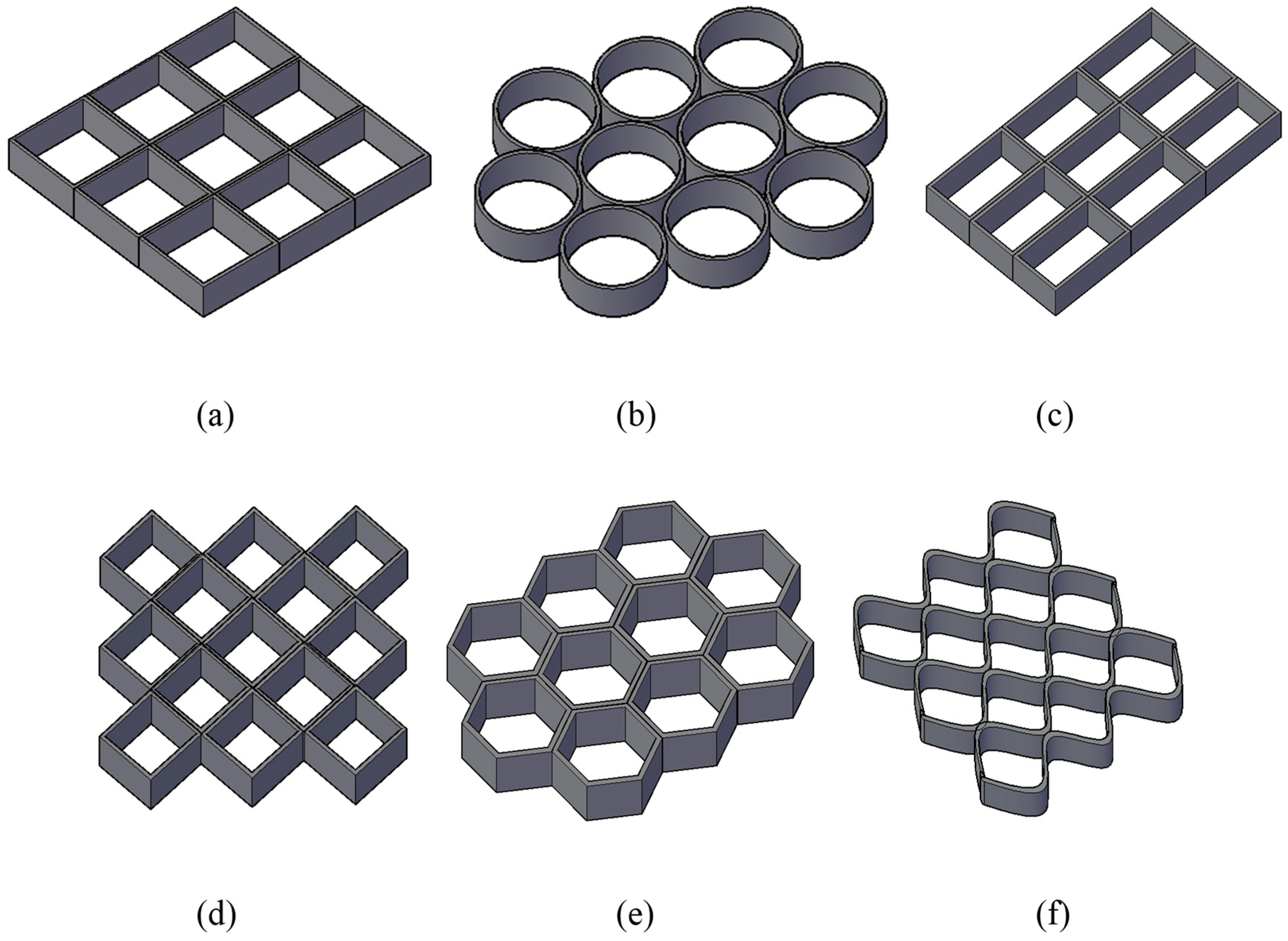
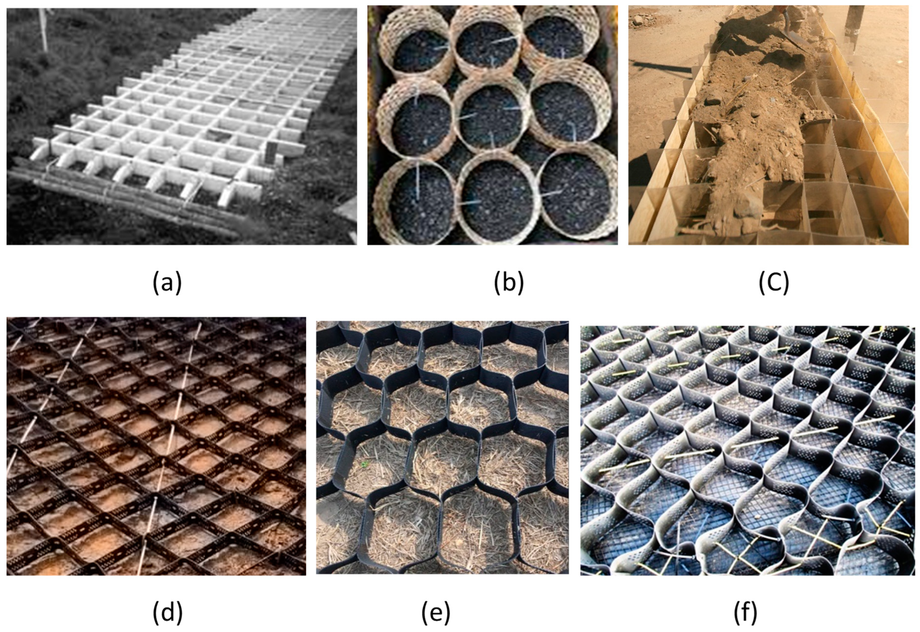
The geometric shape of the geocells has also undergone several transformations from square, circular, rectangular, diamond, and hexagonal to honeycomb. A schematic representation of different pocket shapes of geocells used in some of the earlier studies is shown in Figure 5. Photographs of geocells with different pocket shapes are shown in Figure 6.
The earliest studies on geocells used circular or square-shaped geocells [3,41]. Studies suggest that the square-shaped and circular geocells made up of the same material provide similar improvement if the quantity of material used is the same [27]. The shape of the geocells evolved into the current shape of honeycomb to enclose maximum infill material with minimum perimeter of cells [17]. Moreover, the honeycomb shape facilitates the easy collapse of cells to store greater volumes of geocells in smaller spaces and helps in easy handling and transport. Most of the commercially available geocells today are honeycomb-shaped. Other advantages of the honeycomb shape are its ability to stay intact under vertical loads and its effectiveness in controlling the vertical and horizontal deformations of geocells, even when the cells are filled with marginal soils [45].

2.6. Pattern of Arrangement

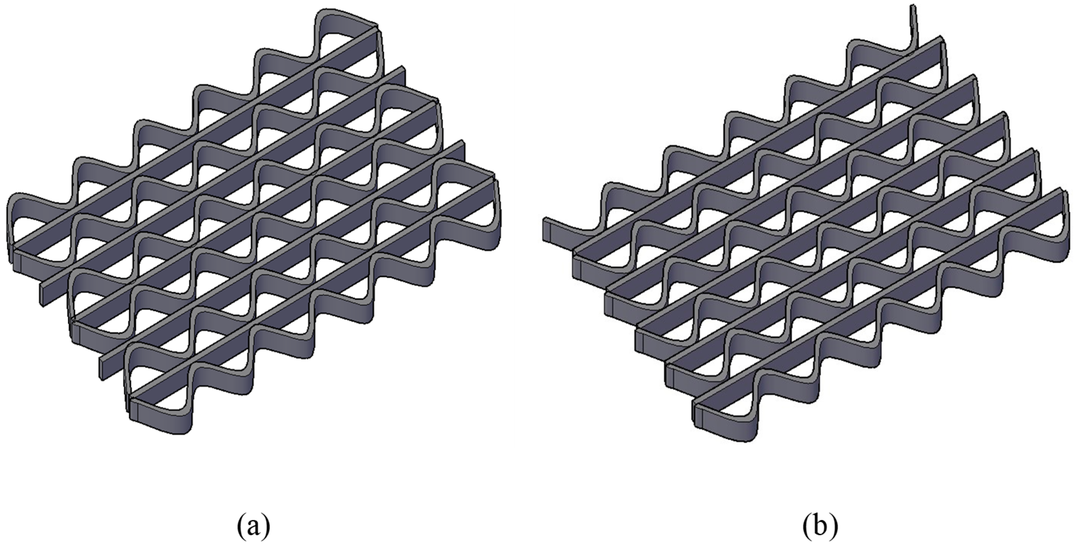
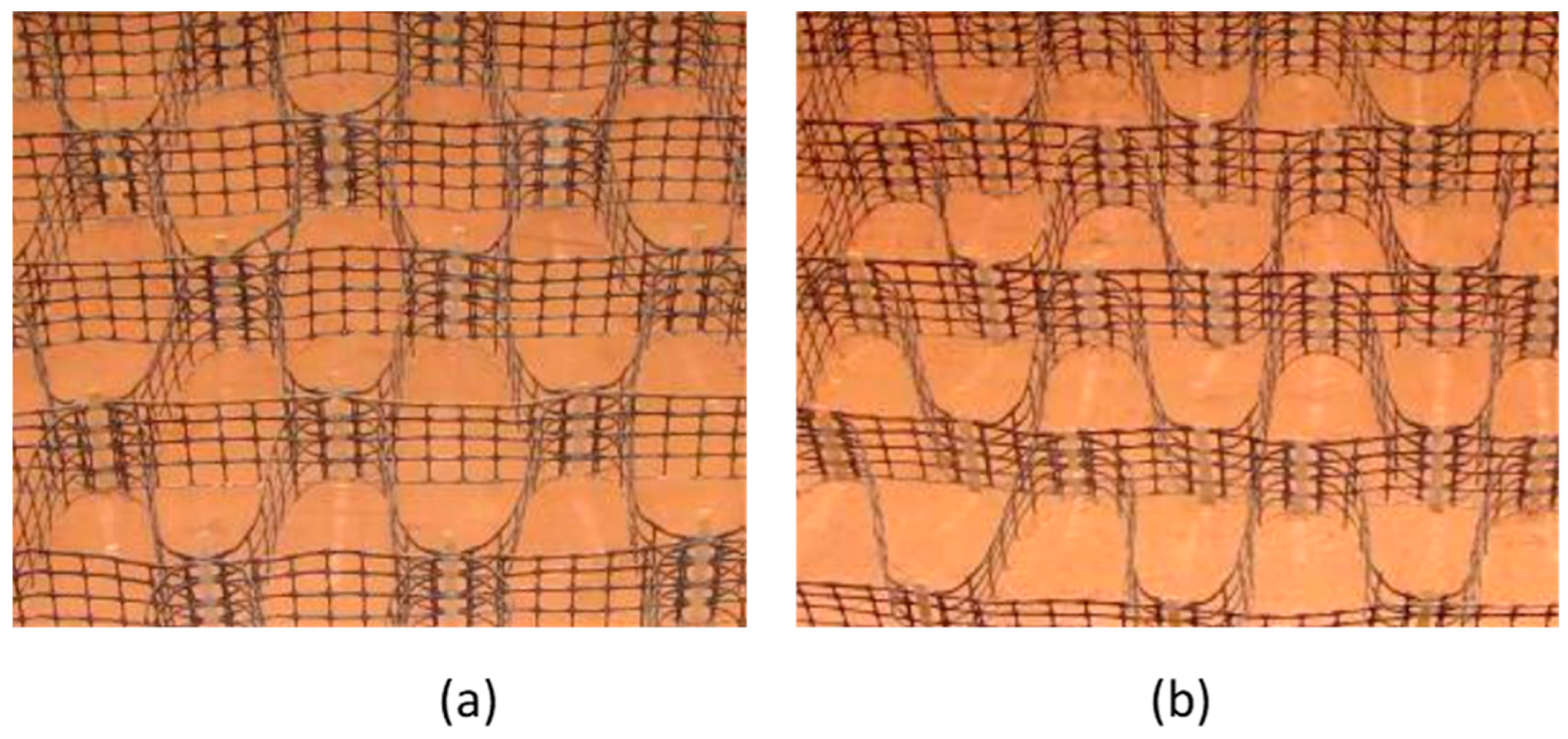
The pattern of arrangement is relevant to geocells fabricated onsite using geogrids. This fabrication can be established in two different patterns, namely, diamond and chevron patterns, as schematically shown in Figure 7. Photographs of geocells fabricated in these two patterns are shown in Figure 8. In both these patterns of arrangement, geogrid strips are vertically erected in the transverse direction first, and diagonal strips are then inserted between the transverse grids using bodkin joints [22,40]. The chevron pattern is better compared to the diamond pattern because it has more joints; thus, failure of some joints may not lead to the failure of the entire mattress. Since the number of joints is more in a chevron pattern, it offers greater rigidity for the same plan area of the geocells. Moreover, the joints in the chevron pattern are easier to form than diamond pattern as the former involves the connection of only two vertical surfaces, whereas the latter has connections involving three grids [40]. Furthermore, studies show that the chevron pattern offers more flexural rigidity than the diamond pattern in geocell-reinforced foundations, especially at higher settlements. When the soil fails in shear at large settlements, the soil surrounding the geocells starts to deform and move upward to surface heave, thus lowering the density of the geocell infill. Under these conditions, a major proportion of the applied load is taken by the geocell walls. Thus, the chevron pattern with higher flexural rigidity offers greater support to loads than the diamond pattern at large settlements [22].

2.7. Embedment Depth of Geocells (u)

The value of optimum embedment depth of geocells cannot be generalized as it is a function of the applied load, height of the geocell layer, geocell pocket size, type of soil, and number of geocell layers [47]. However, the significance of embedment depth is well recognized. If the geocell layer is placed just below the footing, localized stresses of higher magnitudes accumulate in the geocell walls, leading to buckling failure [27]. Moreover, shallow placement restricts the mobilization of adequate confinement within the geocells and interface friction at the top and bottom of the geocell layer because of the reduction in normal stress due to overburden [26,42,48,49].
The soil cushion between the footing and the geocell layer and in between two geocell layers enables the development of effective friction at geocell–soil interfaces. The soil cushion, along with the geocell-reinforced soil composite, behaves as a rigid system, which enables the distribution of the load over a wider area of the underlying soil [13,24,26,27,28,29,50]. The load dispersion mechanism offered by the sand cushion is evident from the measured strains along the height of the geocell wall. The horizontal strains were observed to decrease from a maximum value at the top to a minimum value at the bottom, when the geocell layer was placed at the optimum depth [13]. The soil cushion not only guards the geocell layer from the direct application of loads but also facilitates drainage during the consolidation of the underlying soft soil [23,25]. The soil cushion was found to be effective even under cyclic loading conditions [44]. However, at embedment depths lower than the optimum, the depth of the soil cushion was not sufficient for the mobilization of frictional resistance against shearing; thus, the particles in the cushion squeezed out, resulting in the poor performance of geocell reinforcement [24,27]. At embedment depths greater than the optimum, the composite beam-like behavior of geocells vanishes, and the top cushion and the geocell-reinforced soil behave as two separate entities, leading to the shearing of the topsoil cushion. Thus, the soil lying between the footing and the geocell-reinforced soil composite squeezes out laterally, leading to their poor performance. Moreover, the overlying load also has a direct effect on to the underlying geocell reinforced soil composite [13,22,27]. Furthermore, at greater embedment depths, a major portion of the geocell-reinforced soil composite lies outside the zone of influence of the applied loading. Thus, the reinforcing effect is completely nullified, and the geocell-reinforced soil starts to behave as an unreinforced soil [24,25,26,47,49]. This behavior is observed when the embedment depths are generally greater than the width of the applied loading. Studies with soil cushions made of cohesive soils suggest that it is beneficial to place the footing load directly on the geocell mattress without any soft soil cushion so that the lateral squeezing of the cohesive soil can be avoided [23].

2.8. Number of Geocell Layers (N)

Figure 9 shows a schematic diagram of a foundation reinforced with multiple geocell layers. An increase in the number of geocell layers results in improved performance because of increased soil–geocell contact area, which can contribute to significantly higher frictional resistance, enhanced confinement effect, and its homogeneous stress distribution below the foundation [49,50]. Furthermore, with more geocell layers, the volume of soil under the reinforcement effect increases, resulting in an overall increase in stiffness [16,19]. With multiple geocell layers below the loaded area, the entire pressure bulb within the ground can be encased within the geocell reinforcement, thus completely arresting the lateral and vertical deformations [31,50].
However, the installation of multiple geocell layers requires deeper excavation and filling, which significantly increases the cost of the project. Since geocell reinforcement is provided for shallow foundations and pavements, such deeper excavations are not feasible most of the time. Hence, it is very important to strike a balance between the number of geocell layers and the cost while designing the geocell reinforcement. Furthermore, the literature suggests that the beneficial effects of geocell reinforcement do not linearly increase with the increase in the number of geocell layers beyond a limit [51]. The geocell layers provided below the zone of influence of the load are not subjected to any significant stresses due to the applied load; hence, their contributions to the overall strength and stiffness improvement are minimal [31]. Studies suggest that the geocell layers must be placed in a way that they lie within the influence zone of the applied loads [52].
The resilient characteristics of geocells such as accumulated plastic strains and total settlement of the reinforced bed were reported to improve with the number of geocell layers. Similar to static loading conditions, their improvement became maximum at a particular optimum number; thereafter, their influence was minimal with a further increase in geocell layers. As the number of geocell layer increases, the energy absorbance characteristics offered by them under cyclic loading increase, thus reducing the magnitude of stresses and shocks transferred to the underlying soil [47]. However, unlike static loading conditions where the rate of improvement was higher at higher settlement levels, it became insignificant at higher number of load cycles for heavily reinforced systems during cyclic loading conditions [26,42,48,50,53].
Multiple layers of geocell are usually placed at a vertical spacing between them so that the interactions with the soil are maximum. However, Kargar and Hoessini [39] studied the influence of two- and four-layered geocells without any spacing between them and found that the increase in the number of geocell layers decreased the strength and stiffness characteristics of geocell-reinforced soil beds. In reinforced foundation beds with two geocell layers, tensile strains developed at the lower portion of the geocells broke the continuity of these cells and separated them into individual cells. Due to this discontinuity, the relative sliding between the layers hampered their integrated performance; thus, stresses could not be effectively transferred to greater depths of the underlying soil [52]. Similarly, in the case of reinforced beds with four geocell layers, it was found that the tensile strains in the geocells were not completely mobilized, resulting in a lower improvement in their strength and deformation characteristics. These observations contradict the observations made by earlier researchers with multiple geocell layers separated by a layer of soil.
Mehdipour et al. [49] studied the influence of number of geocell layers in a slope on the factor of safety (FOS) through numerical simulations. It was observed that the FOS of geocell-reinforced slope increased with an increase in the number of geocell layers by increasing the rigidity, which helped in pushing the slip surface away from the slope. While the first geocell layer was found to develop more resistance against the bending and shear deformations of the slope, the remaining layers mainly contributed to the resistance against lateral deformations [49].

3. Properties of Geocell Material

The stiffness and surface roughness of geocell material play a vital role in the performance of geocells. The surface roughness of geocells is essential to mobilize the frictional resistance at the interface. The stiffness of the geocells must be adequate to counteract the membrane stresses developed in the cell walls, which are responsible for the enhanced load support offered by geocells. Geocells with an aspect ratio close to unity predominantly showed tensioned membrane effect at large displacements [14].

3.1. Surface Roughness of Geocells

Studies showed a greater improvement in geocell performance with rough surfaces [11,17,38]. The increase in the roughness of geocell walls increases the angle of interface friction between the cell walls and the infill soil. The vertical frictional resistance offered by the additional confining stresses developed along the geocell walls resists the applied load and, thus, redistributes the load over a larger area [54,55,56,57]. However, some studies reported that extremely rough surfaces had a weakening effect on the strength and deformation of geocell reinforced structures [12]. Furthermore, the surface roughness of geocell walls is not considered as important as the tensile strength of the geocells in the literature [54]. The influence of wall roughness was omitted in many of the analytical models proposed for predicting the strength and deformation characteristics of geocells. In models where the interface friction is considered, the computed deformations of geocells were lesser compared to the models in which the interface friction was omitted [12,57].

3.2. Stiffness of Geocells

The stiffness of geocells refers to the tensile and bending stiffness of the cell walls. Studies showed that the bearing capacity and stiffness improvement factors of the geocell reinforced beds depend on the elastic modulus of the geocells [16]. Compared to planar geosynthetics, geocells exhibit very high tensile and bending stiffness due to their shape and configuration. Hence, geocells, by virtue of their increased stiffness, provide greater load-bearing capacity and reduce lateral deformations under static and cyclic loading scenarios [27,42,58,59]. Higher stiffness offers enhanced confining stresses along the walls of the geocells [31,42,54,60]. Biabani et al. [55] carried out numerical studies on ballast-filled geocells with varying elastic modulus of the geocell material and showed that the variation in modulus was reflected in the tensile stresses developed at the top portion of geocells, while its effect on stresses in the bottom portion was insignificant. Furthermore, studies showed that the performance improvement with the increase in stiffness is not linear, and geocells with relatively lower stiffness perform reasonably well compared to those with higher stiffness [61]. Relative stiffness, which is the stiffness of geocells relative to the subgrade, is the primary factor for the design of geocell-reinforced soil structures. The stiffness of geocells must be adequately larger than that of the subgrade for an efficient reinforcement effect. Insufficient relative stiffness results in a nonuniform distribution of the overlying stresses onto the underlying soil [45].
A thorough review of the literature provided critical inputs for the selection of geocell dimensions and configuration to derive maximum benefits. These inputs aid in the design of geocell reinforcement for various applications and also help in further evolution of geocell reinforcement to enhance its beneficial effects.

4. Soil Properties

Geocells are always in constant interaction with two different categories of soils: the soil filled in the cells, which is referred to as infill soil, and the soil encompassing the geocell layers, which is referred to as native soil. The effects of the properties of infill and native soils are discussed in this section.

4.1. Infill Soil Properties

The infill material in geocells can be either a cohesive or a cohesionless soil. Studies show that the improvement in performance with geocell reinforcement is mainly due to the geocells rather than the infill. Although coarse-grained cohesionless soils are preferred as infill to mobilize greater interface friction, locally available marginal soils were effectively used in many case studies. However, good drainage and non-plasticity of infill material are important to derive the benefits of geocells [33,40]. The gradation of the infill material, especially in the case of cohesionless infill, has shown a significant effect on the performance of the geocell-reinforced structures. Coarse-grained soils and well-graded soils are proven to provide greater benefits [30,61]. In addition to the gradation, the shear strength and elastic modulus of the infill material were found to influence the performance of geocell-reinforced structures under static and cyclic loading conditions [62,63]. As the angle of internal friction of the infill increases, the apparent cohesion developed within the geocells also increases. The increased stiffness offered due to the increased apparent cohesion in geocell-reinforced soil composite prevents the progression of failure surface through these cells [64]. Irrespective of the type of the infill material, the potential failure surface in slopes was enlarged with an increase in infill soil stiffness, mobilizing higher FOS [49,65]. The effects of stiffness must be considered along with the moisture content in the infill soil. Studies on the influence of moisture content in the infill soil of geocells on their performance are limited. Pokharel [16] conducted model studies on geocells filled with two different types of sands, one insensitive to moisture and the other highly sensitive to moisture with an apparent cohesion under unsaturated conditions. Even though the latter has greater stiffness than the former, a greater performance improvement was observed with the former than the latter. The inclusion of geocells induced an apparent cohesion in both the infill soils; however, in the soil sensitive to moisture, the apparent cohesion induced by geocells was significantly lesser.
An increase in relative density of the infill increases the frictional resistance developed at the interfaces. With an increase in infill soil density, a stiffened soil–geocell composite is formed, which distributes the overlying loads to a wider area through the enhanced anchorage effect [66]. This in turn increases the resistance offered by the geocell–soil composite to the propagation of failure surface into the underlying soil, thus improving the overall performance of the geocell layer [22,25]. Furthermore, denser infills increase the stiffness of the soil–geocell composite, offering more resistance to flexural deformations [62].
The confinement offered by the geocells prevents the dilation of dense soils that occurs at large deformations and helps in fully mobilizing the tensile strength of the geocells, leading to an improvement in their performance. The rate of improvement in load-carrying capacity at larger settlements is much higher for soils with higher relative density [17,22,25,52,66]. At higher settlements, loose soils contract and behave like dense soils [66]. The increase in relative density increases the surface heaving due to larger volumetric expansion, as reported by many researchers [22,66]. Dash et al. [66] analyzed the development of strains along the walls of geocells with varying densities of infill. In experiments with denser infill, compressive strains were observed to develop along the boundaries of the geocell mattress due to the formation of a stable soil zone, which could resist the localized transverse expansion of the geocell–soil composite. These compressive strains were absent in the case of loose infill soil. Studies also found that the influence of relative density of infill soil is negligible for geocells with larger pockets [35].
In the field, relative density is controlled through compaction efforts. Studies have shown that increased soil compaction improves the FOS of geocell-reinforced soil slopes. Geocells placed at the lower portion of the slope mobilized higher tensile strength and bending moment since the bottom layers were subjected to greater compaction. However, geocells placed in the bottom regions were subjected to larger residual stresses, resulting in the mobilization of higher frictional resistance at the soil–geocell interface [49].

4.2. Native Soil Properties

As discussed earlier, in general, higher stiffness of the foundation soil results in higher load-carrying capacity of the geocell-reinforced soil beds [45,55,67]. With higher stiffness of the native soil, higher frictional resistance mobilizes between the geocell layer and the native soil, which enhances the stiffness and rigidity of the reinforced soil bed [12,19]. Such stiffer soils provide great support to the overlying geocell layer and help in redistributing the loads over a larger area, leading to negligible transfer of stresses to the underlying subgrades [32,45]. However, as discussed in the context of the relative stiffness of geocell material, the stiffness of the native soil need not be too high to derive the complete benefits of geocell reinforcement. Unlike planar geosynthetics which rely completely on the tensile strength of material and interface friction, geocells rely on their interconnected cellular network and configuration to improve the load-carrying capacity. Hence, their usage for soft soil conditions is well demonstrated in literature and case studies [59]. The predominance of a reinforcement effect was observed at higher settlements in stiffer subgrades and at lower settlements in softer subgrades [59].
Although the application of geocells in various civil engineering structures is proven to be beneficial, their use in transportation applications has received the maximum attention in literature.

5. Geocells in Transportation Applications

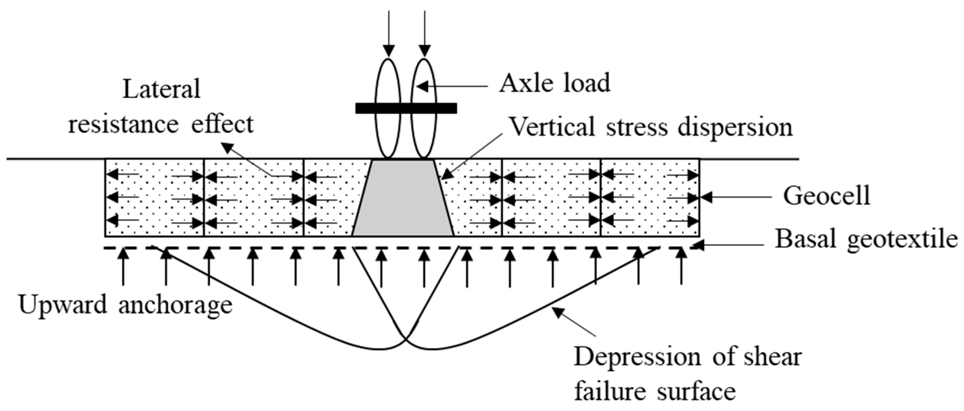
Most of the pavements fail well before their design life due to the poor quality of construction materials, improper compaction, overstressing, and improper preparation of pavement subgrade. Such failures can be avoided either by using thicker pavements or by increasing the rigidity of various subsurface layers. Since the former method is expensive, the latter method has gained worldwide popularity. Many researchers have studied the successful application of geocell reinforcement in pavements and road embankments to enhance their performance. The idea of cellular confinement systems was initially introduced with their applications in pavements. A schematic representation of a typical geocell-reinforced pavement and its internal mechanisms is shown in Figure 10.
Several studies on paved and unpaved roads with geocell reinforcement are available in the literature. Studies showed that the inclusion of geocells improved the load capacity and stiffness of the underlying subgrade under both static and cyclic loading conditions [16,42,68]. The confining stresses in geocells mobilize frictional resistance at the geocell–soil interface and, thus, restrain the soil from moving outside the loaded area. The stiffened geocell-reinforced soil composite acts as a slab and redistributes the pavement load to a larger area, as shown in Figure 10. Thus, the vertical stresses on the subgrade decrease, resulting in a reduction in deformations and improved load–displacement performance of pavements. In addition to these advantages, the inclusion of geocells also helps in reducing the fatigue cracking and creep deformations [69,70].
Studies showed that the geocell reinforced pavements had higher percentages of elastic deformations as compared to the unreinforced pavements, which is beneficial in reducing the rut depth or CPDs in the subgrade [16,68]. Saride et al. [37] showed that geocells were successful in reducing the CPD in a subgrade by one-fourth of the CPD in unreinforced subgrade even after 50 cycles of 400 kPa traffic loading [37]. Similarly, rut depths were reduced by 22% after 100 cycles in geocell-reinforced base courses under cyclic loading of 550 kPa [71].
The quantitative benefit of using geocells in pavements under cyclic loading is often expressed in terms of traffic benefit ratio (TBR). TBR is defined as the ratio of the number of load cycles required to attain a given rut depth in reinforced pavements to the corresponding rut depth in unreinforced pavements. Saride et al. [37] measured a high TBR value of 23 at 10% settlement in geocell-reinforced pavement bases under a cyclic load of 400 kPa [37]. A TBR value of 1.87 was observed at a settlement ratio of 15% in cyclic plate load tests conducted by Kumar and Saride [71].
Since laboratory cyclic plate load tests cannot fully replicate the load history generated by the moving vehicle loads, accelerated pavement tests (APT) or full-scale wheel load tests are recommended to understand the realistic role of geocells on pavement performance [16,72]. Pokharel [16] conducted accelerated pavement tests to study the influence of infill materials on the performance of unpaved low volume roads with the inclusion of geocells under a tire pressure of 552 kPa. Aggregates, quarry waste (QW), and demolition waste from reclaimed asphalt pavements (RAP) were used as infill in these tests. Results showed that the strength, serviceability, and durability of the unpaved roads improved with the inclusion of geocells due to lateral confinement, stress dispersion, and beam effects. The inclusion of geocells increased the load dispersion angle by 13.4°, 11.6°, and 6.5°, respectively, for reinforced aggregate, RAP waste, and QW [16]. Yang et al. [72] also carried out APT tests on unreinforced and reinforced unpaved sections using the same testing facility. The wheels with a tire pressure of 550 kPa were run back and forth through the unpaved road sections at a frequency of 10 passes per minute. The tests on unreinforced sections could not be completed because of excessive rut depths. The rut depth measured in the same section when it was reinforced with geocells was only 4.8 cm, even after 5000 load cycles.
Al-Qadi and Hughes [73] studied the performance of a weak subgrade with California bearing ratio (CBR) of 4 during a reconstruction project in Pennsylvania. The subgrade was reinforced with a geocell layer supported by a basal geogrid. The back analysis of deflection obtained from a falling height deflectometer showed that the inclusion of a geocell improved the bearing capacity by a factor of 2–3 immediately after construction. Emerslen and Meyer [74] conducted field studies on geocell-reinforced RAP structures used in the reconstruction of K23 road connecting the cities of Braunschweig and Hannover, Germany. Results from the vehicle crossing tests using a truck of 41 tons at different speeds showed that the vertical stresses on the subgrade were reduced by 30% with geocell reinforcement. Results of falling deflectometer tests using a dynamic impulse of 50 kN showed that the deflections on the geocell-reinforced road surface were 15% lower compared to those measured in unreinforced pavements. Latha et al. [75] compared the relative benefits of different geosynthetics placed at the interface of base course and subgrade in an unpaved road on which a vehicle was moving. Even though all the reinforced sections performed better than the unreinforced section, the geocells were the most effective among them in terms of reduction in rut depth and increase in TBR. The TBR value for the geocell-reinforced section was found to be 16.5 at a rut depth of 71.5 mm, whereas the corresponding value for the geogrid-reinforced section was 6.5. Rajagopal et al. [76] rehabilitated an unpaved road built over black cotton soil using geocells in Maharashtra, India. This road showed severe rutting before reinforcement and was reconstructed at least three times. The reinforced sections behaved effectively even after 3 years of completion of the project.
The use of geocells for rehabilitating pavements is a common practice. A two-way road in Hangal, Northern Karnataka of India, was rehabilitated by reinforcing the base course with geocells. The pavement was damaged due to two consecutive harsh monsoon seasons, developing excessive potholes and reflective cracks. The geocell reinforcement was effective in repairing the damage, and the road functioned well even after more than a decade of rehabilitation [44]. Many other such case studies of road rehabilitation using geocells are reported in several parts of the world. In all the case studies, the addition of geocells as reinforcement in pavements considerably reduced the thickness of various pavement layers. This reduction is directly proportional to the reduction in the material and transportation costs, in addition to providing sustainable benefits in terms of reduced carbon footprint due to reduction in mining and transportation of materials and reduction in construction time. A few studies showed that the inclusion of geocells reduced the thickness of granular subbase layers by 50% [77]. Although the initial investments in rehabilitation using geocells are slightly higher, the overall benefits are much higher compared to all other ground improvement and reinforcement techniques since geocell reinforcement substantially reduces maintenance costs [78]. Another advantage is the possibility of using locally available marginal soils as infill if good-quality cohesionless soils are not available, which is not possible in the case of geotextile or geogrid reinforcement. Many case studies on the use of waste materials such as granulated rubber, RAP waste, quarry waste, foundation slag, bottom ash, fly ash, and reclaimed construction waste as pavement materials as infill or as base course material, along with geocells, are available in the literature [70]. Studies demonstrated the effectiveness of granulated rubber as geocell infill in distributing the stresses over a larger area, thereby reducing the deformations by 60–70% [78]. The performance of geocells filled with construction and quarry waste under cyclic loads was ascertained by several researchers [79,80]. A field study of pavement bases made of industrial byproducts such as foundation slag, bottom ash, and fly ash using geocells over a 1.4 km section along the Wisconsin state highway showed that the pavement did not show any distress even after 12 months of its construction [81]. Furthermore, the stiffness of these pavement bases was found to be equal to or greater than that of the conventional stone subbase. The perforations on the geocell walls compensated for the poor drainage characteristics of the infill waste materials and reduced the water-induced stresses within the pavements [81]. Recently, Palese et al. [82] reported a case study of rebuilding the section of a high-speed railway track in Indianapolis using geocells. The track, which was undergoing excessive deformations due to poor subgrade conditions and requiring annual maintenance, was successfully rebuilt with geocells, saving huge maintenance costs and improving the performance. Thus, geocells help in the effective use of several waste materials in pavements, contributing to the sustainability goals of clean cities, responsible consumption, recycling, and innovative infrastructure.

6. Conclusions

Geocells, which are polymeric interconnected cells filled with granular soil, provide excellent support to loads under static and cyclic loading scenarios. The counteracting confining stresses in the interconnected geocells provide all-around confinement to the infill soil; thus, these additionally developed pressures are the prime reason for their various reinforcement mechanisms. The primary reinforcement mechanisms in geocell-reinforced structures include lateral resistance, vertical stress dispersion, and tensioned membrane effect. The various reinforcing actions provide greater benefits in terms of strength improvement and reduction in deformations. This leads to their widespread applications in various geotechnical structures such as embankments, foundations, pavements, slopes, reinforced earth walls, railways, erosion control and slope protection, and waste containment systems.
The present-day configuration of geocells evolved over the years, as a function of the needs and constraints associated with different applications of geocells. Among the plethora of applications of geocells, their use in transportation infrastructure, including pavements, embankments, and retaining walls, is well documented and practiced. Many parameters that can influence the performance of geocells in various applications include geocell dimensions, pocket size, aspect ratio, layout, number of layers, surface features, properties of cell material, and its relative stiffness with the subgrade, infill soil, and native soil. Although the selection of these parameters depends on the application and the loading conditions, general guidelines for their selection are provided by various researchers. In pavement applications, geocells are proven to provide numerous benefits, which include their ability to support cyclic loads, reduce rut depths, and improve traffic benefit ratio. They contribute to the sustainability of pavements by reducing the overall thickness of various pavement layers and effectively utilizing the locally available marginal soils and waste materials as infill. Thus, geocell-reinforced pavements incur lower material and maintenance costs, less construction time, and significantly lower carbon emissions during construction by reducing the material mining and transportation. Many case studies vouch for the superior performance of geocell reinforcement in the construction and rehabilitation of pavements and demonstrated their benefits to control fatigue cracking and creep deformations. The traffic benefit ratio (TBR) values, which are indicative of the better performance of the pavement to the traffic compared to unreinforced pavements, reported in the literature were as high as 16–23 for geocell-reinforced pavements, which are much higher compared to geogrid-reinforced pavements.

Author Contributions

Conceptualization, A.K. and G.M.L.; methodology, A.K. and G.M.L.; resources, A.K. and G.M.L.; writing—original draft preparation, A.K.; writing—review and editing, G.M.L.; visualization, A.K. and G.M.L.; supervision, G.M.L. All authors have read and agreed to the published version of the manuscript.

Funding

This research received no external funding.

Institutional Review Board Statement

Not applicable.

Informed Consent Statement

Not applicable.

Data Availability Statement

No new data were created or analyzed in this study. Data sharing is not applicable to this article.

Conflicts of Interest

The authors declare no conflict of interest.

References

  1. Webster, S.L.; Watkins, J.E. Investigation of Construction Techniques for Tactical Bridge Approach Roads across Soft Ground; US Waterways Experiment Station: Vicksburg, MS, USA, 1977; Volume 2. [Google Scholar]
  2. Rea, C.; Mitchell, J.K. Sand Reinforcement Using Paper Grid Cells; ASCE Spring Convention and Exhibit: Pittsburgh, PA, USA, 1978; pp. 24–28. [Google Scholar]
  3. Meyer, K.G. Managing Degraded off-Highway Vehicle Trails in Wet, Unstable, and Sensitive Environments; USDA Forest Service, Technology and Development Program, Missoula Technology and Development Center: Missoula, MT, USA, 2002; Available online: https://www.google.co.in/books/edition/Managing_Degraded_Off_highway_Vehicle_Tr/wc7sYHoj1j0C?hl=en (accessed on 18 July 2023).
  4. Rajagopal, K.; Krishnaswamy, N.R.; Latha, G.M. Behavior of sand confined with single and multiple geocells. Geotext. Geomembr. 1999, 17, 171–184. [Google Scholar] [CrossRef]
  5. Leshchinsky, B.; Ling, H. Effects of geocell confinement on strength and deformation behavior of gravel. J. Geotech. Geoenvironment. Eng. 2013, 120, 339–351. [Google Scholar] [CrossRef]
  6. Latha, G.M. Geocells for transportation geotechnical applications. Indian Geotech. J. 2021, 50, 602–613. [Google Scholar] [CrossRef]
  7. Latha, G.M.; Somwanshi, A. Effect of reinforcement form on the bearing capacity of square footings on sand. Geotext. Geomembr. 2009, 27, 399–412. [Google Scholar] [CrossRef]
  8. Gedela, R.; Karpurapu, R. Influence of pocket shape on numerical response of geocell reinforced foundation systems. Geosynth. Int. 2021, 28, 327–337. [Google Scholar] [CrossRef]
  9. Henkel, D.J.; Gilbert, G.D. The effect of the rubber membrane on the measured triaxial compression strength of clay specimens. Geotechnique 1951, 3, 20–29. [Google Scholar] [CrossRef]
  10. Bathurst, R.J.; Karpurapu, R. Large-Scale Triaxial Compression Testing of Geocell-Reinforced Granular Soils. Geotech. Test. J. 1993, 16, 296–303. [Google Scholar]
  11. Garcia, R.S.; Neto, J.A. Stress-dependent method for calculating the modulus improvement factor in geocell-reinforced soil layers. Geotext. Geomembr. 2021, 48, 145–157. [Google Scholar] [CrossRef]
  12. Zhang, L.; Zhao, M.; Zou, X.; Zhao, H. Deformation analysis of geocell reinforcement using Winkler model. Comput. Geotech. 2009, 36, 977–983. [Google Scholar] [CrossRef]
  13. Dash, S.K.; Rajagopal, K.; Krishnaswamy, N.R. Behavior of geocell-reinforced sand beds under strip loading. Can. Geotech. J. 2007, 43, 905–916. [Google Scholar] [CrossRef]
  14. Mandal, J.N.; Gupta, P. Stability of geocell-reinforced soil. Constr. Build. Mater. 1994, 8, 54–61. [Google Scholar] [CrossRef]
  15. Bush, D.I.; Jenner, C.G.; Bassett, R.H. The design and construction of geocell foundation mattresses supporting embankments over soft grounds. Geotext. Geomembr. 1990, 9, 83–98. [Google Scholar] [CrossRef]
  16. Pokharel, S.K. Experimental Study on Geocell-Reinforced Bases under Static and Dynamic Loading. Ph.D. Thesis, University of Kansas, Lawrence, KS, USA, 2010. [Google Scholar]
  17. Gedela, R.; Kalla, S.; Sudarsanan, N.; Karpurapu, R. Assessment of load distribution mechanism in geocell reinforced foundation beds using digital imaging correlation techniques. Transp. Geotech. 2021, 31, 100664. [Google Scholar] [CrossRef]
  18. Dash, S.K.; Rajagopal, K.; Krishnaswamy, N.R. Performance of different geosynthetic reinforcement materials in sand foundations. Geosynth. Int. 2004, 11, 35–41. [Google Scholar] [CrossRef]
  19. Tafreshi, S.M.; Sharifi, P.; Dawson, A.R. Performance of circular footings on sand by use of multiple-geocell or-planar geotextile reinforcing layers. Soils Found. 2016, 55, 984–997. [Google Scholar] [CrossRef]
  20. Liu, Y.; Deng, A.; Jaksa, M. Failure mechanisms of geocell walls and junctions. Geotext. Geomembr. 2019, 46, 104–120. [Google Scholar] [CrossRef]
  21. Dash, S.K.; Rajagopal, K.; Krishnaswamy, N.R. Strip footing on geocell reinforced sand beds with additional planar reinforcement. Geotext. Geomembr. 2001, 19, 519–5211. [Google Scholar] [CrossRef]
  22. Dash, S.K.; Krishnaswamy, N.R.; Rajagopal, K. Bearing capacity of strip footings supported on geocell-reinforced sand. Geotext. Geomembr. 2001, 19, 235–255. [Google Scholar] [CrossRef]
  23. Sitharam, T.G.; Sireesh, S.; Dash, S.K. Model studies of a circular footing supported on geocell-reinforced clay. Can. Geotech. J. 2005, 41, 693–703. [Google Scholar] [CrossRef]
  24. Thallak, S.G.; Saride, S.; Dash, S.K. Performance of surface footing on geocell-reinforced soft clay beds. Geotech. Geol. Eng. 2007, 25, 499–514. [Google Scholar] [CrossRef]
  25. Lal, D.; Sankar, N.; Chandrakaran, S. Behaviour of square footing on sand reinforced with coir geocell. Arab. J. Geosci. 2017, 10, 345. [Google Scholar] [CrossRef]
  26. Tafreshi, S.M.; Dawson, A.R. Comparison of bearing capacity of a strip footing on sand with geocell and with planar forms of geotextile reinforcement. Geotext. Geomembr. 2010, 28, 72–114. [Google Scholar] [CrossRef]
  27. Sherin, K.S.; Chandrakaran, S.; Sankar, N. Effect of geocell geometry and multi-layer system on the performance of geocell reinforced sand under a square footing. Int. J. Geosynth. Ground Eng. 2017, 3, 20. [Google Scholar] [CrossRef]
  28. Dash, S.K.; Reddy, P.D.T.; Raghukanth, S.T.G. Subgrade modulus of geocell-reinforced sand foundations. Proc. Inst. Civ. Eng. Ground Improv. 2008, 160, 79–117. [Google Scholar] [CrossRef]
  29. Muthukumar, S.; Sakthivelu, A.; Shanmugasundaram, K.; Mahendran, N.; Ravichandran, V. Performance assessment of square footing on jute geocell-reinforced sand. Int. J. Geosynth. Ground Eng. 2019, 5, 25. [Google Scholar] [CrossRef]
  30. Shin, E.C.; Kang, H.H.; Park, J.J. Reinforcement efficiency of bearing capacity with geocell shape and filling materials. KSCE J. Civ. Eng. 2017, 21, 1627–1655. [Google Scholar] [CrossRef]
  31. Tafreshi, S.M.; Shaghaghi, T.; Mehrjardi, G.T.; Dawson, A.R.; Ghadrdan, M. A simplified method for predicting the settlement of circular footings on multi-layered geocell-reinforced non-cohesive soils. Geotext. Geomembr. 2015, 42, 332–343. [Google Scholar] [CrossRef]
  32. Saride, S.; Gowrisetti, S.; Sitharam, T.G.; Puppala, A.J. Numerical simulation of geocell-reinforced sand and clay. Proc. Inst. Civ. Eng. Ground Improv. 2009, 161, 185–198. [Google Scholar] [CrossRef]
  33. Latha, G.M.; Rajagopal, K.; Krishnaswamy, N.R. Experimental and theoretical investigations on geocell-supported embankments. Int. J. Geomech. 2006, 6, 30. [Google Scholar] [CrossRef]
  34. Madhavi Latha, G.; Dash, S.K.; Rajagopal, K. Equivalent continuum simulations of geocell reinforced sand beds supporting strip footings. Geotech. Geol. Eng. 2008, 26, 387–398. [Google Scholar] [CrossRef]
  35. Mhaiskar, S.Y.; Mandal, J.N. Investigations on soft clay subgrade strengthening using geocells. Constr. Build. Mater. 1996, 10, 281–286. [Google Scholar] [CrossRef]
  36. Cheung, Y.K.; Chan, H.C. Finite element analysis. In Reinforced Concrete Deep Baems; Kong, F.K., Ed.; Blackie Publication: Glasgow, UK, 1990; pp. 204–237. [Google Scholar]
  37. Saride, S.; Rayabharapu, V.K.; Vedpathak, S. Evaluation of rutting behavior of geocell reinforced sand subgrades under repeated loading. Indian Geotech. J. 2015, 44, 378–388. [Google Scholar] [CrossRef]
  38. Hegde, A.; Sitharam, T.G. 3-Dimensional numerical modelling of geocell reinforced sand beds. Geotext. Geomembr. 2015, 42, 171–181. [Google Scholar] [CrossRef]
  39. Kargar, M.; Mir Mohammad Hosseini, S.M. Effect of reinforcement geometry on the performance of a reduced-scale strip footing model supported on geocell-reinforced sand. Sci. Iran. 2017, 24, 96–109. [Google Scholar] [CrossRef] [Green Version]
  40. Krishnaswamy, N.R.; Rajagopal, K.; Latha, G.M. Model studies on geocell supported embankments constructed over a soft clay foundation. Geotech. Test. J. 2000, 23, 44–49. [Google Scholar]
  41. Shimizu, M.; Inui, T. Increase in the bearing capacity of ground with geotextile wall frame. In Proceedings of the Fourth International Conference on Geotextiles Geomembranes and Related Products, Hague, The Netherlands, 28 May–1 June 1990; pp. 1–29. [Google Scholar]
  42. Yang, X. Numerical Analyses of Geocell-Reinforced Granular Soils under Static and Repeated Loads. Ph.D. Thesis, University of Kansas, Lawrence, KS, USA, 2010. [Google Scholar]
  43. Saha, D.C.; Mandal, J.N. Performance of reclaimed asphalt pavement reinforced with bamboo geogrid and bamboo geocell. Int. J. Pavement Eng. 2020, 21, 571–582. [Google Scholar] [CrossRef]
  44. Bagli, S.P. A tryst with geosynthetics. Indian Geotech. J. 2022, 52, 1003–1053. [Google Scholar] [CrossRef]
  45. Leshchinsky, B.; Ling, H.I. Numerical modeling of behavior of railway ballasted structure with geocell confinement. Geotext. Geomembr. 2013, 36, 33–42. [Google Scholar] [CrossRef]
  46. Rai, M. Geocell-Sand Mattress Overlying Soft Clay Subgrade: Behaviour under Circular Loading. Ph.D. Thesis, IIT Guwahati, Guwahati, India, 2010. [Google Scholar]
  47. Khalaj, O.; Moghaddas Tafreshi, S.N.; Mask, B.; Dawson, A.R. Improvement of pavement foundation response with multi-layers of geocell reinforcement: Cyclic plate load test. Geomech. Eng. 2015, 9, 373–395. [Google Scholar] [CrossRef]
  48. Sitharam, T.G.; Sireesh, S. Effects of base geogrid on geocell-reinforced foundation beds. Geomech. Geoengin. Int. J. 2006, 1, 207–216. [Google Scholar] [CrossRef]
  49. Mehdipour, I.; Ghazavi, M.; Moayed, R.Z. Numerical study on stability analysis of geocell reinforced slopes by considering the bending effect. Geotext. Geomembr. 2013, 37, 23–34. [Google Scholar] [CrossRef]
  50. Davarifard, S.; Tafreshi, S.M. Plate load tests of multi-layered geocell reinforced bed considering embedment depth of footing. Procedia Earth Planet. Sci. 2015, 15, 105–110. [Google Scholar] [CrossRef] [Green Version]
  51. Arvin, M.R.; Zakeri, A.; Bahmani Shoorijeh, M. Using finite element strength reduction method for stability analysis of geocell-reinforced slopes. Geotech. Geol. Eng. 2019, 37, 1443–1456. [Google Scholar] [CrossRef]
  52. Tafreshi, S.M.; Dawson, A.R. A comparison of static and cyclic loading responses of foundations on geocell-reinforced sand. Geotext. Geomembr. 2012, 32, 54–68. [Google Scholar]
  53. Zhang, L.; Zhao, M.; Shi, C.; Zhao, H. Bearing capacity of geocell reinforcement in embankment engineering. Geotext. Geomembr. 2010, 28, 475–482. [Google Scholar] [CrossRef]
  54. Hegde, A.; Sitharam, T.G. Experiment and 3D-numerical studies on soft clay bed reinforced with different types of cellular confinement systems. Transp. Geotech. 2017, 10, 73–84. [Google Scholar] [CrossRef]
  55. Biabani, M.M.; Ngo, N.T.; Indraratna, B. Performance evaluation of railway subballast stabilised with geocell based on pull-out testing. Geotext. Geomembr. 2016, 43, 569–581. [Google Scholar] [CrossRef] [Green Version]
  56. Hegde, A.M.; Sitharam, T.G. Three-dimensional numerical analysis of geocell-reinforced soft clay beds by considering the actual geometry of geocell pockets. Can. Geotech. J. 2015, 51, 1206–1397. [Google Scholar] [CrossRef]
  57. Maheshwari, P.; Babu, G.S. Nonlinear deformation analysis of geocell reinforcement in pavements. Int. J. Geomech. 2017, 17, 03916043. [Google Scholar] [CrossRef]
  58. Latha, G.M. Design of geocell reinforcement for supporting embankments on soft ground. Geomech. Eng. 2011, 3, 87–130. [Google Scholar] [CrossRef]
  59. Wang, G.Y.; Zhang, J.P.; Zhao, J.W. Numerical analysis of geocell protective slope stability. Appl. Mech. Mater. 2013, 352, 505–610. [Google Scholar] [CrossRef]
  60. Sireesh, S.; Sitharam, T.G.; Dash, S.K. Bearing capacity of circular footing on geocell–sand mattress overlying clay bed with void. Geotext. Geomembr. 2009, 27, 89–98. [Google Scholar] [CrossRef]
  61. Biabani, M.M.; Indraratna, B.; Ngo, N.T. Modelling of geocell-reinforced subballast subjected to cyclic loading. Geotext. Geomembr. 2016, 43, 479–493. [Google Scholar] [CrossRef] [Green Version]
  62. Tang, X.; Yang, M. Investigation of flexural behavior of geocell reinforcement using three-layered beam model testing. Geotech. Geol. Eng. 2013, 31, 752–765. [Google Scholar] [CrossRef]
  63. Han, J.; Thakur, J.K.; Parsons, R.L.; Pokharel, S.K.; Leshchinsky, D.; Yang, X. A summary of research on geocell-reinforced base courses. In Proceedings of the Design and Practice of Geosynthetic-Reinforced Soil Structures; Ling, H., Gottardi, G., Cazzuffi, D., Han, J., Tatsuoka, F., Eds.; DEStech Publications, Inc.: Lancaster, PA, USA, 2013; pp. 350–357. [Google Scholar]
  64. Song, F.; Liu, H.; Ma, L.; Hu, H. Numerical analysis of geocell-reinforced retaining wall failure modes. Geotext. Geomembr. 2018, 45, 284–296. [Google Scholar] [CrossRef]
  65. Mehdipour, I.; Ghazavi, M.; Ziaie Moayed, R. Stability analysis of geocell-reinforced slopes using the limit equilibrium horizontal slice method. Int. J. Geomech. 2017, 17, 05917007. [Google Scholar] [CrossRef]
  66. Dash, S.K. Influence of relative density of soil on performance of geocell-reinforced sand foundations. J. Mater. Civ. Eng. 2010, 22, 523–528. [Google Scholar] [CrossRef]
  67. Hegde, A.; Sitharam, T.G. Experimental and numerical studies on footings supported on geocell reinforced sand and clay beds. Int. J. Geotech. Eng. 2013, 7, 345–353. [Google Scholar] [CrossRef]
  68. Suku, L.; Prabhu, S.S.; Ramesh, P.; Babu, G.S. Behavior of geocell-reinforced granular base under repeated loading. Transp. Geotech. 2016, 9, 17–30. [Google Scholar] [CrossRef]
  69. Li, W.; Han, S.; Han, X.; Yao, Y. Experimental and numerical analysis of mechanical properties of geocell reinforced reclaimed construction waste composite base layer. Constr. Build. Mater. 2021, 304, 124587. [Google Scholar] [CrossRef]
  70. Zhou, H.; Wen, X. Model studies on geogrid-or geocell-reinforced sand cushion on soft soil. Geotext. Geomembr. 2008, 26, 231–238. [Google Scholar] [CrossRef]
  71. Kumar, V.V.; Saride, S. Rutting behavior of geocell reinforced base layer overlying weak sand subgrades. Procedia Eng. 2016, 143, 1409–1416. [Google Scholar] [CrossRef] [Green Version]
  72. Yang, X.; Han, J.; Pokharel, S.K.; Manandhar, C.; Parsons, R.L.; Leshchinsky, D.; Halahmi, I. Accelerated pavement testing of unpaved roads with geocell-reinforced sand bases. Geotext. Geomembr. 2012, 32, 95–103. [Google Scholar] [CrossRef]
  73. Al-Qadi, I.L.; Hughes, J.J. Field evaluation of geocell use in flexible pavements. Transp. Res. Rec. 2000, 1709, 26–35. [Google Scholar] [CrossRef]
  74. Emersleben, A.; Meyer, N. Bearing capacity improvement of gravel base layers in road constructions using geocells. In Proceedings of the 12th International Conference of International Association for Computer Methods and Advances in Geomechanics (IACMAG’08), Goa, India, 1–6 October 2008; pp. 3538–3545. [Google Scholar]
  75. Latha, G.; Nair, A.; Hemalatha, M. Performance of geosynthetics in unpaved roads. Int. J. Geotech. Eng. 2010, 4, 337–349. [Google Scholar] [CrossRef]
  76. Rajagopal, K.; Chandramouli, S.; Parayil, A.; Iniyan, K. Studies on geosynthetic-reinforced road pavement structures. Int. J. Geotech. Eng. 2014, 8, 287–298. [Google Scholar] [CrossRef]
  77. Rajagopal, K.; Veeragavan, A.; Chandramouli, S. Studies on geocell reinforced road pavement structures. In Proceedings of the Geosynthetics Asia, Bangkok, Thailand, 13–15 December 2012; pp. 497–502. [Google Scholar]
  78. Tafreshi, S.M.; Khalaj, O.; Dawson, A. R Repeated loading of soil containing granulated rubber and multiple geocell layers. Geotext. Geomembr. 2014, 42, 25–38. [Google Scholar] [CrossRef]
  79. Thakur, J.K.; Han, J.; Parsons, R.L. Creep behavior of geocell-reinforced recycled asphalt pavement bases. J. Mater. Civ. Eng. 2013, 25, 1533–1542. [Google Scholar] [CrossRef]
  80. Sheikh, I.R.; Mandhaniya, P.; Shah, M.Y. A parametric study on pavement with geocell reinforced rock quarry waste base on dredged soil subgrade. Int. J. Geosynth. Ground Eng. 2021, 7, 32. [Google Scholar] [CrossRef]
  81. Edil, T.B.; Benson, C.H.; Bin-Shafique, M.; Tanyu, B.F.; Kim, W.H.; Senol, A. Field evaluation of construction alternatives for roadways over soft subgrade. Transp. Res. Rec. 2002, 1786, 36–48. [Google Scholar] [CrossRef]
  82. Palese, J.W.; Hartsough, C.H.; Zarembski, A.M.; Thompson, H.; Ling, H.L. Life cycle benefits of subgrade reinforcement using geocell on a highspeed railway—A case study. In Proceedings of the AREMA Conference, Indianapolis, IN, USA, 17–20 September 2017; pp. 1–14. [Google Scholar]
Figure 1. Early version of geocells used by US Waterways Experimentation Station at Vicksburg, MS, USA [1].
Sustainability 15 11773 g001
Figure 2. Schematic representation of geocell reinforced foundation bed.
Sustainability 15 11773 g002
Figure 3. Mechanisms of geocell reinforcement: (a) confinement effect (plan view); (b) stress dispersion effect (sectional elevation); (c) lateral resistance effect on a single geocell (front view); (d) membrane effect (sectional elevation).
Sustainability 15 11773 g003
Figure 4. Commercially available geocells: (a) collapsed form; (b) expanded form.
Sustainability 15 11773 g004
Figure 5. Schematic representation of geocells with different pocket shapes: (a) square [3,41]; (b) circular [3,4,32,41]; (c) rectangular [42]; (d) diamond [5]; (e) hexagonal [42]; (f) honeycomb [7,17].
Sustainability 15 11773 g005
Figure 6. Photographs of geocells with different pocket shapes: (a) square [1]; (b) circular [43]; (c) rectangular [1]; (d) diamond [44]; (e) hexagonal (product brochure of Weifang City Huateng Plastic Products, China); (f) honeycomb [44].
Sustainability 15 11773 g006
Figure 7. Schematics of different patterns of geocells fabricated using geogrids: (a) diamond; (b) chevron.
Sustainability 15 11773 g007
Figure 8. Photographs of geocells fabricated using geogrids [46]: (a) diamond; (b) chevron.
Sustainability 15 11773 g008
Figure 9. Soil beds reinforced with multiple geocell layers.
Sustainability 15 11773 g009
Figure 10. Geocell reinforcement mechanisms in pavements.
Sustainability 15 11773 g010
Table 1. Typical properties of commercial geocells.
PropertyValue
Density0.932–0.95 g/cm3
Strip width50–300 mm
Strip thickness 1.53 mm (±10%)
Percentage of perforations to cell wall area6–22%
Ultimate tensile strength 16–25 kN/m
Junction peel strength7–10 kN/m
Elongation at maximum load20% (±15%)
Dynamic modulus at service temperature (−60 °C to 60 °C)650–800 MPa
Resistance to UV degradation 250–400 min
Cumulative permanent deformation (creep resistance)2.7–3.5%
Disclaimer/Publisher’s Note: The statements, opinions and data contained in all publications are solely those of the individual author(s) and contributor(s) and not of MDPI and/or the editor(s). MDPI and/or the editor(s) disclaim responsibility for any injury to people or property resulting from any ideas, methods, instructions or products referred to in the content.