Article

Alleviation of Power Quality Issues in MVF-DEANF-PLL Based Solar PV Systems under Polluted Grid Conditions

by
Balasubramanian Mohan
1,*,
Saravanan Siddhan
2 and
Nagarajan Chinnadurai
3
1
Department of Electrical and Electronics Engineering, Government College of Engineering, Tirunelveli 627007, Tamilnadu, India
2
Department of Electrical and Electronics Engineering, Muthayammal Engineering College, Rasipuram 637408, Tamilnadu, India
3
Department of Electrical and Electronics Engineering, Muthayammal College of Engineering, Rasipuram 637408, Tamilnadu, India
*
Author to whom correspondence should be addressed.
Sustainability 2023, 15(21), 15487; https://doi.org/10.3390/su152115487
Submission received: 25 September 2023 / Revised: 21 October 2023 / Accepted: 26 October 2023 / Published: 31 October 2023

Abstract

:
Solar energy is a sustainable and environmentally safe power source due to its widespread availability and cleanliness. Nowadays, the grid-integrated solar photovoltaic system (SPVS) has to work with a polluted grid, an imbalanced load, and changing solar irradiation. When the grid is polluted, it is also crucial to enhance power quality (PQ) at a common coupling point (CCP) while supplying significantly distorted and unreliable loads. For effective synchronization and the production of unit templates, it is necessary to retrieve positive sequence components (PSCs) from distorted/imbalanced grid voltages. In this study, a control algorithm for a grid-integrated SPVS is developed using a multi-variable filter dual-enhanced adaptive notch filter phase-locked loop (MVF-DEANF-PLL) which offers seamless grid synchronization and PQ issue alleviation. In a polluted grid environment, the proposed control approach aids in the reduction in current/voltage harmonics, DC offset, unity power factor (UPF) operation, and rapid estimation of sequence components. Even in unbalanced grid conditions, the proposed control approach efficiently extracts PSCs of both unbalanced load current and polluted CCP grid voltages. These PSCs are utilized to generate unit templates and reference source currents. By using a flexible step-size incremental conductance (FSSINC) maximum power point tracking (MPPT) technique, the highest available power of SPVS is gathered. MATLAB/Simulink is utilized for modelling a 7.22 kW SPV system, and results from simulations which depict that the proposed algorithm efficiently resolves PQ concerns in distribution networks with a polluted grid. Test observations of a 1 kW laboratory-developed SPVS prototype were recorded in compliance with the IEEE-519 standard. The suggested control technique complies with the aforementioned standards by providing a sinusoidal balanced source current that has a THD of 2.5%. Comparisons between the proposed control’s performance and that of a conventional SRF-PLL-based control technique were also performed.

1. Introduction

The increasing popularity of solar photovoltaic power generation can be attributed to its customizable size and user-friendly operations. Solar energy is considered to be a sustainable and environmentally friendly source of power due to its cleanliness and unlimited availability. Solar PV (SPV) power generation is uncertain since solar irradiation is fluctuating. Thus, grid-integrated SPVS are credible options [1]. Therefore, the control of a grid-integrated SPVS is employed in this study to alleviate the uncertainty associated with SPV power generation. Moreover, during night hours, the grid-integrated SPVS is utilized as DSTATCOM. To mitigate the issue of sunlight’s intermittency, it is imperative to capture the greatest power output during periods of solar irradiation. The attainment of the highest power output is contingent upon several conditions, including solar irradiation levels, temperature, and other relevant variables. Numerous MPPT strategies have been documented in the academic literature to maximize the gathering of solar energy. The utilization of the perturb and observe (P&O) technique is prevalent in MPPT controls, owing to their simple and effortless incorporation [2]. However, it includes steady-state fluctuations near MPP, which consequently increase power loss. The incremental conductance (INC) approach can minimize steady-state fluctuations and also offers greater tracking consistency [3]. Furthermore, the utilization of neural network [4] and fuzzy [5] techniques centres in capturing the non-linear attributes of PV arrays. However, the applicability of these approaches is constrained in terms of their versatility.
In the case of non-linear load, effective control of SPVS is needed to provide adequate PQ, function with UPF, and reduce harmonics. There are many proven strategies in the literature for reducing PQ issues when the load is imbalanced. In the synchronous reference frame theory (SRFT) framework, low-pass filters are employed to mitigate the impact of harmonics on the d-axis components when operating under imbalanced load conditions [6]. However, it is important to note that this approach can result in a decrease in the speed of the system’s response. The notch filter (NF)-based method is effective in mitigating PQ problems [7]. However, difficulties arise in achieving an adequate frequency response, parameter selection, and realization due to its optimal phase and magnitude characteristics. Matching the duration of sampling and the grid’s interval in polluted grid environments poses a challenge in discrete Fourier transform (DFT)-based algorithms [8]. The Instantaneous Reactive Power Theory (IRPT) relies on the computation of power that incorporates the impact of changes in voltage [9]. Therefore, oscillations in grid voltage also impact the estimation of reference current.
A wide range of adaptive approaches have been documented in the scholarly literature to mitigate PQ issues in the presence of distorted loads. The Least Mean Square (LMS) method is extensively utilized in various applications due to its adaptability, ease of implementation, and excellent performance [10]. The performance of the LMS approach is poor in dynamic circumstances when it comes to minimizing stable-state fluctuations. The Least Mean Fourth (LMF) method includes higher-order elements and exhibits reduced stable state distortion [11]. Under imbalanced load circumstances, the LMF exhibits inadequate response, experiences DC offsets, and demonstrates slow convergence. Nevertheless, SPVS that incorporate adaptive algorithms may encounter challenges when dealing with DC offsets and imbalanced grid voltages.
Several control approaches utilizing integrators have been documented in the academic literature. The second-order generalized integrator (SOGI) is commonly employed due to its elementary design and strong filtering capabilities [12]. However, the concerns about SOGI are the presence of harmonics and the limited ability to remove DC offsets in both the quadrature and direct axis signals. Alternatively, the problem of DC offsets and harmonics alleviation can be resolved by utilizing the PSCs information derived from the CCP voltages. The utilization of the MVF, which has a dual architecture within αβ frames, is employed for obtaining PSCs of the grid voltage necessary for synchronization [13]. An additional concern pertains to the existence of DC offsets in the CCP voltages, resulting in the appearance of DC offsets in PSCs obtained by dual architectures. However, under imbalanced and distorted grid environments, it is essential to track the grid voltage phase rapidly as well as to remove harmonic content from the phase information.
Numerous strategies for PLLs and frequency-locked loops (FLLs) have been extensively studied in the existing literature for extracting grid voltage data under distorted operating conditions. The use of adaptive notch filter (ANF) structures, which effectively eliminate dependency on trigonometric calculations, allows for the extraction of the PSCs of grid voltage [14]. The SOGI/ANF-FLL structures lack rejection of DC offsets, and the inclusion of additional sections for sequence computation introduces duplication. The utilization of dual SOGI (DSOGI)-FLL has the potential to remove the necessity for additional sections in sequence computation [15]. Nevertheless, the effectiveness of the system declines as a result of its susceptibility to subharmonics. The utilization of second-order SOGI-FLL, which involves the substitution of integrator units in a filter with SOGI units, has been found to have enhanced filtering capabilities [16]. However, it is important to note that this approach also comes with a significant increase in computation. The DSOGI-PLL is a commonly employed technique for calculating the PSCs of CCP voltages [17]. This method is particularly effective in mitigating the effects of imbalanced grid voltage. Nevertheless, the DSOGI-PLL’s functionality is negatively affected when there is an imbalanced DC offset present.
To overcome the aforementioned challenges, it is suggested to integrate an MVF pre-filter with dual-enhanced ANF-PLL. The primary goal of this study is to incorporate solar power into the electrical grid while ensuring the preservation of balanced and sinusoidal grid currents, particularly under polluted grid circumstances. A novel MVF-DEANF-PLL-based phase tracking approach was proposed to extract PSCs of both non-linear load current and distorted grid CCP voltages in the SPVS. These PSCs are utilized to extract highly distorted load currents’ fundamental components as well as to carry out unit template computations. The generation of reference source current also makes use of these unit templates to improve PQ indices at CCP. Using a hysteresis current controller (HCC), the VSC switches’ gate signals are developed by comparing reference and actual source current. For validating the efficacy of the suggested control, a two-stage SPVS structure integrated with a polluted grid was developed. The SPVS operates efficiently at its highest level of power through the implementation of a duty ratio governance mechanism assisted by an FSSINC MPPT approach.
This paper has been organized as follows: Section 2 provides a brief description of the grid-integrated SPVS that has been employed in this study. Section 3 provides a comprehensive analysis of the control approach employed for controlling the operation of the VSC and boost converter. Section 4 examines the simulation response of the suggested system under both SPV and non-SPV hours. In Section 5, a quantitative examination is conducted on the experimental findings from the suggested system to validate its simulation responses. The conclusions of the study are summarized in Section 6.

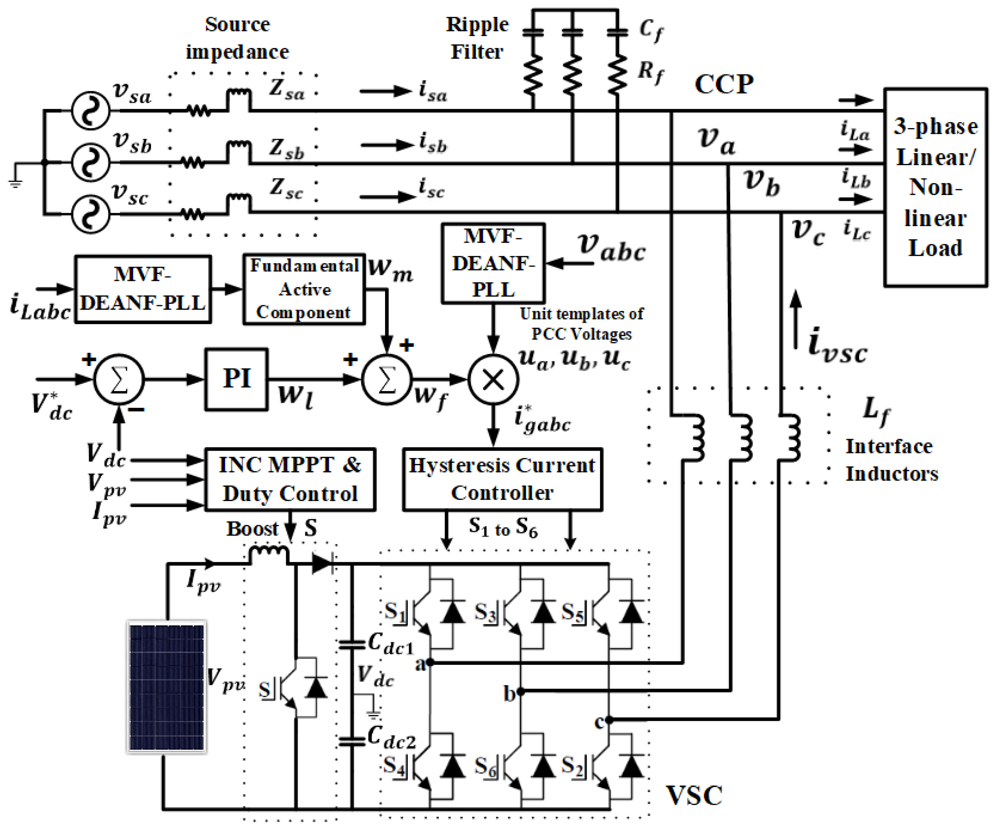
2. System Configuration

The implementation of MVF-DEANF-PLL control in an SPVS integrated with a polluted grid is illustrated in Figure 1. Through VSC and a boost converter, the SPV system fed the grid with PV-produced power. The VSC also performs harmonic alleviation, load balancing, and PQ enhancement at CCP as a DSTATCOM. Since the CCP voltages are polluted, it is not recommended to utilize the CCP voltage templates directly for constructing a reference current and synchronization. Therefore, the PSCs of CCP voltages are extracted using the MVF-DEANF-PLL-based control method which was utilized to develop unit templates.

3. Control Approach

3.1. Maximum Power Extraction

In an SPV system, a boost converter with duty ratio control was employed to ensure that the SPV array was consistently working at its maximum power point (MPP). Historically, the conventional approaches to determining the MPP employed a predetermined step size. However, these traditional methods encountered a compromise between the level of precision and the rate of convergence. Here, the boost converter was operated with appropriate gate pulses that were applied using the FSSINC MPPT control methodology [18]. Its objective was to provide a quick and effective way to enhance tracking dynamics. The suggested MPPT methodology has a flexible step size that dynamically adjusts the size of the step taken in every iteration, depending on the deviation of the present point of operation from a newly estimated MPP. The suggested approach offers enhanced speed of convergence while maintaining accuracy. The power collection from the SPV system was at its highest when the point at which it operates was kept at the peak of the P–V curve. It develops reference PV voltage ( V p v * ) by using measured PV voltage ( V p v ) and current ( I p v ). The V p v * specifies the voltage of the SPV system near the MPP. To achieve MPP operation of the SPV system, the voltage of the DC-link ( V d c ) in the VSC is actively regulated to match the DC-link voltage reference ( V d c * ) through a PI controller.
The configuration of the FSSINC MPPT method is clearly stated as follows:
d I p v d V p v > I p v V p v   ,   V p v * < V m p   ,   V p v * = V p v _ o l d * + Δ V
d I p v d V p v = I p v V p v   ,   V p v * = V m p   ,   V p v * = V p v _ o l d *
d I p v d V p v I p v V p v   ,   V p v *   V m p   ,   V p v * = V p v _ o l d * Δ V
where V m p is the voltage at the MPP point and Δ V is the change in voltage.
The DC-link voltage ( V d c ) and V p v * are utilized in the duty ratio ( α * ) calculation:
α * ( k ) = 1 V p v * ( k ) V d c ( k )
The gate pulse (S) of this converter’s switch was developed by comparing a sawtooth wave with this duty ratio.

3.2. Conventional SRF-PLL
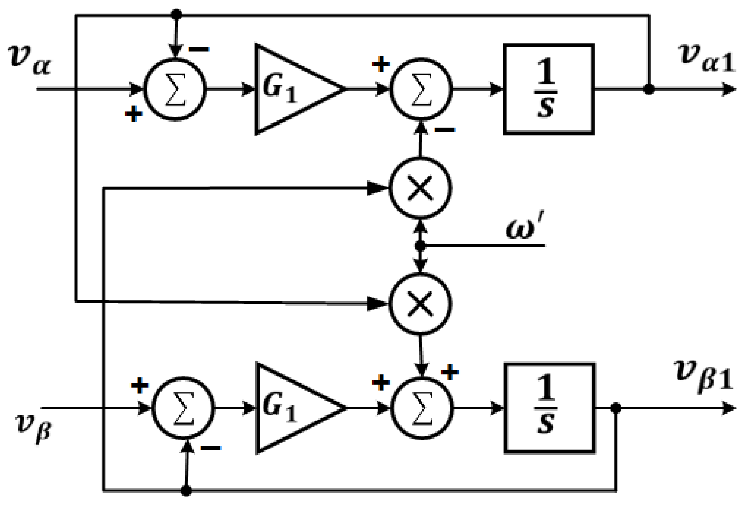
The SRF-PLL is often utilized in three-phase systems [19,20]. It synchronizes the revolving reference frame of the phase-locked loop with the vector of the grid voltage to identify the instantaneous phase. In Figure 2, the PI controller was utilized to establish a reference voltage for the direct or quadrature axis, which was then adjusted to zero to ensure lock with the utility voltage vector. In scenarios where the utility grid environment is free from harmonic distortions and imbalances, the utilization of a high bandwidth SRF-PLL can yield a rapid and precise response of the fundamental components of the utility supply voltages. Conversely, the utilization of SRF-PLL is not viable for sources that are imbalanced/distorted.
It is recommended to convert the CCP voltages ( v a ,   v b ,   v c ) into its α β components ( v α ,   v β ) initially.
[ v α v β ] = [ T α β ] [ v a v b v c ]
The Park transformation described below is utilized for converting α β components into d q components ( v d ,   v q ).
[ v d v q ] = [ T d q ] [ v α v β ]
where transformation matrices are:
[ T α β ] = 2 3 [ 1 1 2 1 2 0 3 2 3 2 ]
[ T d q ] = [ c o s θ s i n θ s i n θ c o s θ ]

3.3. MVF Structure

The fundamental components of v α   a n d   v β are computed by MVF, as depicted in Figure 3, while preserving the voltage amplitude and phase relationships [21,22]. The MVF also reduces the input signals direct and inverse harmonics components. This MVF filter’s transfer function is,
H ( s ) = v α β 1 ( s ) v α β ( s ) = G 1 ( s + G 1 ) + j ω ( s + G 1 ) 2 + ω 2
where G 1 and ω are the gain and center frequency.
Then, the fundamental components of v α   and   v β coming from the MVF’s output are,
v α 1 ( s ) = G 1 s   [ v α ( s ) v α 1 ( s ) ] ω s   v β 1 ( s )
v β 1 ( s ) = G 1 s   [ v β ( s ) v β 1 ( s ) ] + ω s   v α 1 ( s )
where v a 1 and v β 1 are the MVF’s filtered output signals.

3.4. Dual Enhanced Adaptive Notch Filter
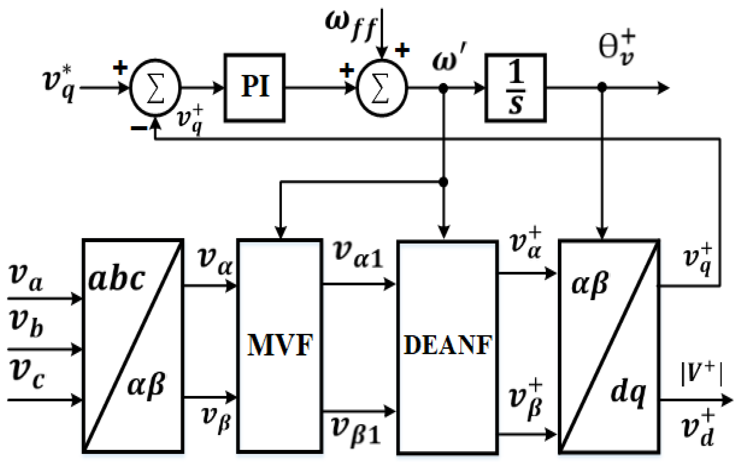
The proposed EANF module shown in Figure 4 mitigates the impact of the fundamental frequency negative sequence (FFNS) component, leading to a doubling of power frequency oscillation in SRF-PLL. The proposed approach effectively separates the fundamental frequency positive sequence (FFPS) and FFNS components.
Here the signal v served as the input, while the signal labelled as v represents the output. Additionally, the quadrature signal was identified as q v . This notch filter possesses a frequency adaptive capability, allowing it to track the grid frequency in response to changes in the frequency of the grid voltage. The differential equations presented below can be used to describe the proposed EANF [23].
x ¨ = ω e
e = 2 ξ u 2 ξ x ˙ ω x
    ω ˙ = η x ω e
The variables η and ξ are crucial in determining the precision and speed of the estimation of the grid frequency. If the input signal of the EANF is sinusoidal v = A s i n ( ω t + φ ) and has an angular frequency equivalent to ω , the mathematical expression of the EANF will yield a distinct solution as
[ x x ˙ ω ] = [ A ω c o s ( ω t + φ ) A s i n ( ω t + φ ) ω ]
As depicted in Figure 4, the orthogonal resultant signals v and q v can be acquired: as
v = x ˙ = A s i n ( ω t + φ )
q v = ω x = A c o s ( ω t + φ )
It uses e and q v as feedback controls to estimate ω , which is also used to perform adaptive control over frequency while interference in the input signal’s frequency occurs. The proposed EANF unit transfer function may be derived as
D ( s ) = v ( s ) v ( s ) = 2 ξ ω s s 2 + 2 ξ ω s + ω 2
Q ( s ) = q v ( s ) v ( s ) = 2 ξ ω 2 s 2 + 2 ξ ω s + ω 2
Typically, to obtain the FFPS component in synchronization applications for grid-connected PLLs, two EANFs are used in parallel with the fundamental frequency positive sequence calculator (FFPSC). The Dual EANF (DEANF) block model is depicted in Figure 5.
In DEANF the orthogonal signals v α ,   q v α , v β   and   q v β are determined from v α   and   v β . Subsequently, the aforementioned signals are given as FFPSC’s input for extracting FFPS components v α   +   and   v β   + as given below,
[ v α   + v β   + ] = 1 2 [ D ( s ) Q ( s ) Q ( s ) D ( s ) ] [ v α v β ]

3.5. MVF–DEANF-PLL

Figure 6 illustrates the integrated system of MVF-DEANF-PLL to retrieve fundamental PSCs of CCP voltages. Here, the Clarke transformation was utilized to convert the unbalanced/distorted CCP voltages ( v a ,   v b ,   v c ) to the α β frame ( v α , v β ). To reduce harmonics at the entrance of DEANF, these distorted v α   and   v β were filtered by MVF, and their fundamental components v α 1   and   v β 1 were retrieved. Then, its output was delivered to DEANF with FPSC. The proposed filter was also utilized for developing a 90°-phase shift and alleviating harmonics and DC offset. The v d   +   and   v q   + were obtained from v a   +   and   v β   + using Park transformation.
[ v d   + v q   + ] = [ cos Δ v   + sin Δ v   + sin Δ v   + cos Δ v   + ]   [ v α   + v β   + ]
Subsequently, the amplitude and phase of CCP voltage’s PSCs were computed.
| V + | = ( v d   + ) 2 + ( v q   + ) 2
tan θ v   + = v q   + v d   +  

3.6. Generation of VSC Gate Pulses

The proposed control also extracted the PSCs of the load current ( i d   +   and   i q   + ) in d q axis, as depicted in Figure 7, and its active component ( w m ) was also computed.
w p = [ ( i d   + ) 2 + ( i q   + ) 2 ] 1 2
tan θ i   + = i q   + i d   +  
w m = w p   cos ( θ v   + θ i   + )
The computation of VSC loss ( w l ) and fundamental current magnitude ( w f ) was carried out in the following manner [24],
w l ( n ) = w l ( n 1 ) + K p { e d c ( n ) e d c ( n 1 ) } + K I [ e d c ( n ) ]
w f ( n ) = w m ( n ) + w l ( n )
where e d c is the DC link voltage error,
e d c ( n ) = V d c * ( n ) V d c ( n )
The unit templates ( u a , u b , u c ) are,
u a = v a   + V m , u b = v b   + V m , u c = v c   + V m
where, v a + ,   v b + ,   v c + are PSCs of CCP voltages
V m = 2 3 ( v a + ) 2 + ( v b + ) 2 + ( v c + ) 2
The following expression was utilized to estimate the reference source current i s a b c * ,
i s a * = u a x w f ,   i s b * = u b x w f ,   i s c * = u c x w f  
This i s a b c * was compared with i s a b c in HCC to develop VSC switch gate signals.

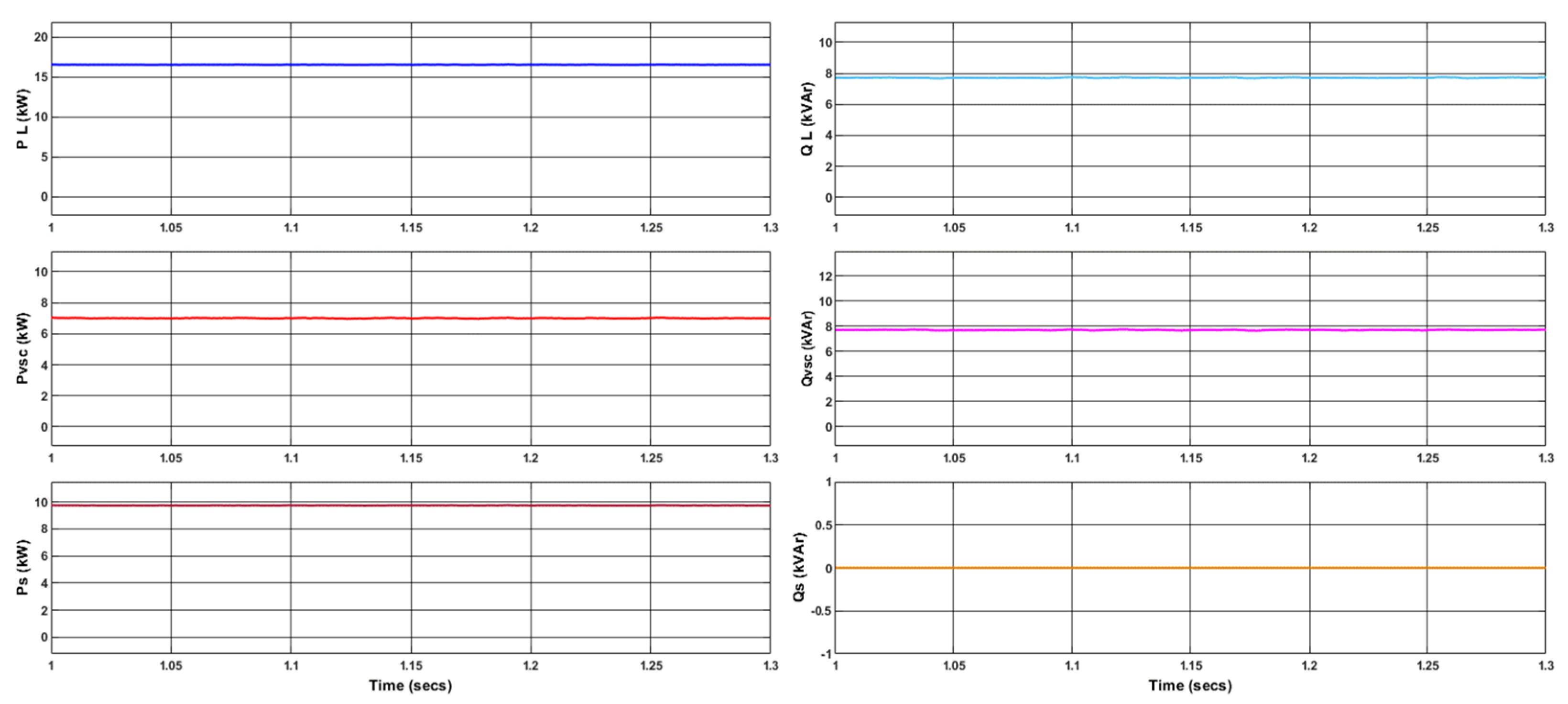
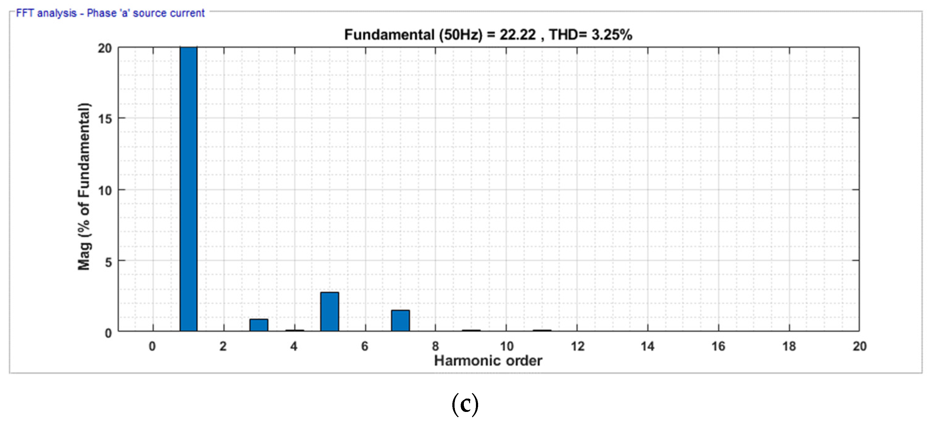
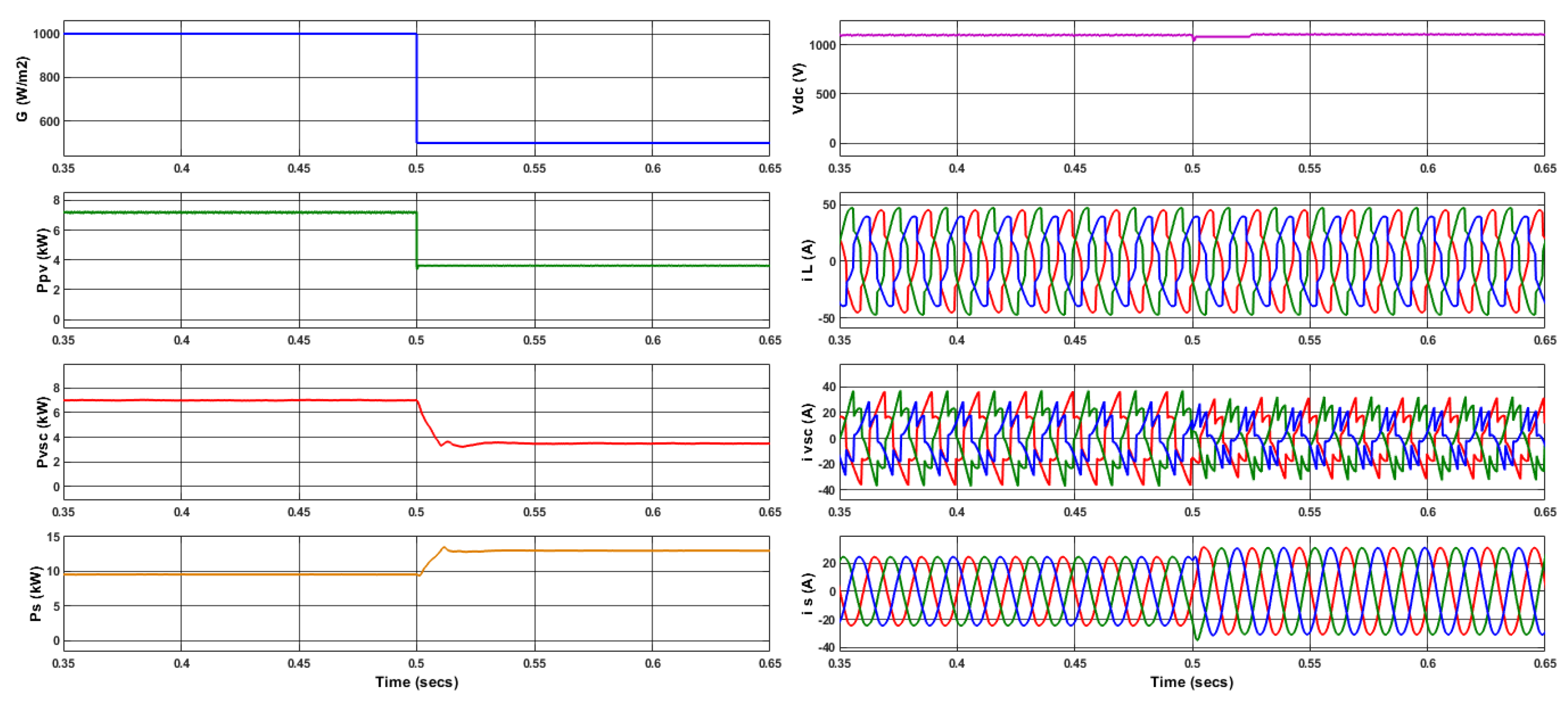
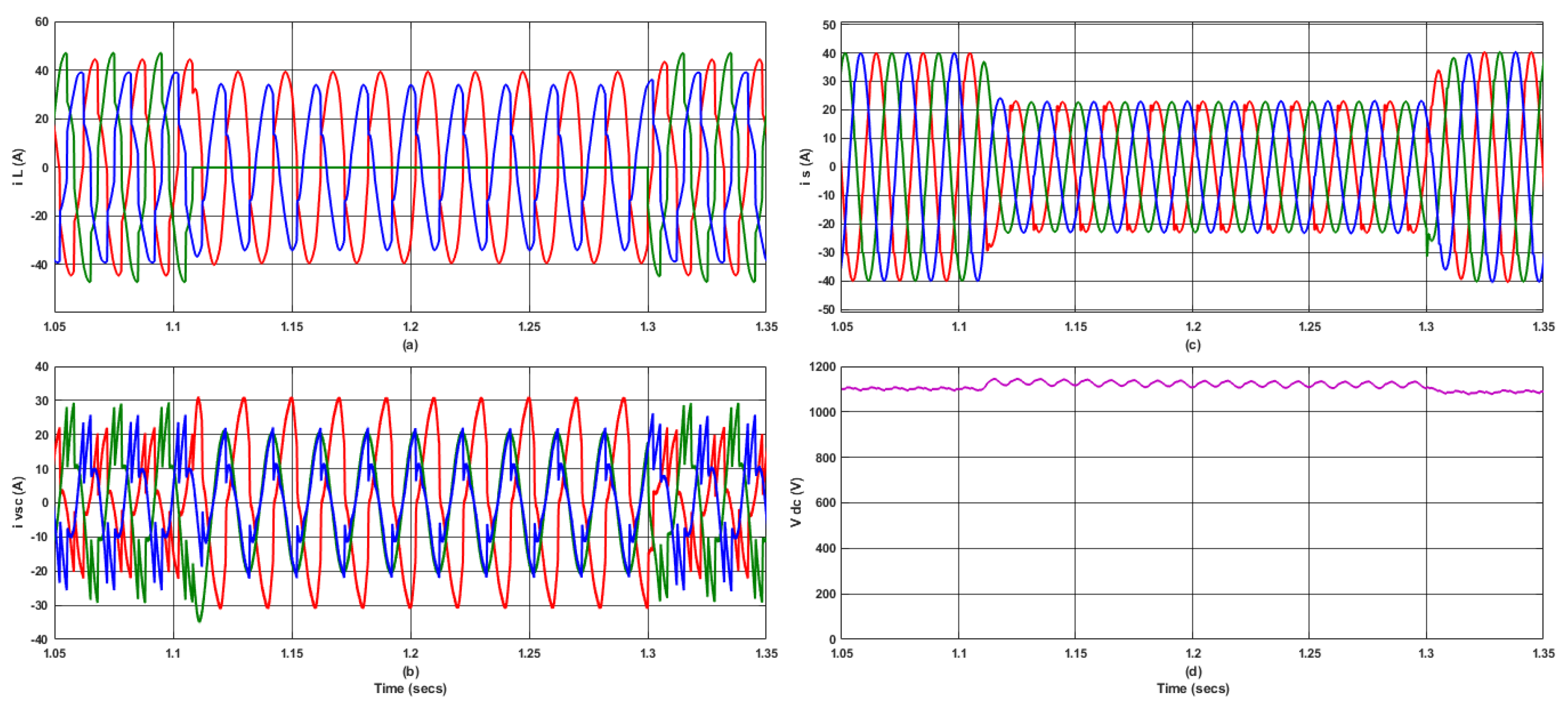
4. Simulation Studies

The proposed system’s performance was evaluated via simulation using MATLAB R2022b/Simulink software. For simulated performance demonstration with varying solar irradiation and load imbalance, a 7.22 kW SPVS (values are provided in the Appendix A) with a linear/non-linear load was taken into consideration. The proposed system’s performance was evaluated in comparison with that of the existing SRF-PLL-based control methodology. The evaluation of the proposed control’s efficiency was conducted under the following scenarios:

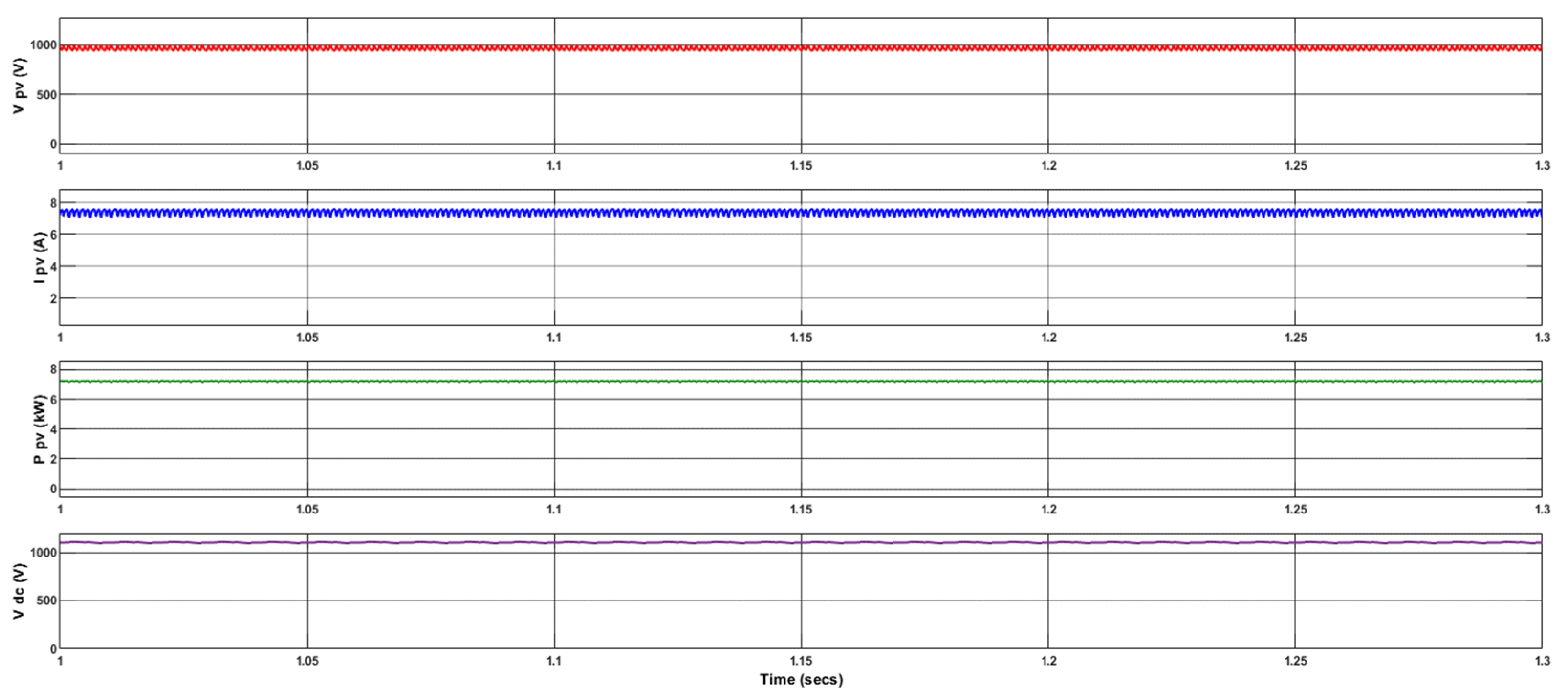
4.1. Response at Constant P p v

Here, the evaluation of the proposed system’s effectiveness was carried out at constant P p v with solar irradiation of 1000 W/m2. The VSC assisted the SPVS in delivering active power to the utility grid. It also compensated for the load’s reactive power and enhances power quality indices at CCP.
The FSSINC MPPT method’s effectiveness in functioning about MPP ( P p v ) of 7.22 kW is evident from Figure 8. The SPVS operated with a V p v of 966.5 V and I p v of 7.47 A, which closely approximate the values of V m p   and   I m p . Also, through the boost converter’s duty ratio α control, the V d c   was regulated around 1100 V.
The existence of distorted grid circumstances resulted in imbalanced/distorted CCP voltages. The unbalanced/distorted V c c p is depicted in Figure 9a. Phase a, b, and c of the three-phase voltage/current waveforms were shown in all images as red, green, and blue colour waveforms, respectively. To achieve efficient synchronization and produce unit templates, it was imperative to extract PSCs out of imbalanced/distorted grid CCP voltages. The PSCs of V c c p were effectively captured by MVF-DEANF-PLL control, as illustrated in Figure 9b. The suggested control approach efficiently evaluated the magnitude of PSCs in the α β frame and d q axis. The d q axis ( v d   +   and   v q   + ) and α β frame ( v α   +   and   v β   + ) magnitudes of PSCs are displayed in Figure 9c. These components were utilized for the estimation of unit templates depicted in Figure 9d. The source current reference ( i s a b c * ) was developed using these unit templates.
Figure 10 illustrates that the load currents ( i L a b c ) exhibited non-linear characteristics and imbalances as a result of the presence of polluted grid circumstances. Despite the presence of non-linear/imbalanced load currents ( i L a b c ), utility supply currents ( i s a b c ) maintained balanced/sinusoidal characteristics with a magnitude of 17.32 A by the efficient injection of compensating current ( i v s c ) by the suggested control mechanism.
Figure 11 highlights the information about the sharing of active/reactive power among the supply, VSC, and load. The measurement of the load’s active power consumption ( P L ) yields a value of 16.5 kW. The SPVS system was responsible for delivering approximately 7 kW ( P v s c ) within this total requirement. The utility supply ( P s ) was responsible for delivering the balance of active power demanded by the load and compensating for losses in the VSC. The estimated power supplied by the utility ( P s ) was around 9.75 kW. Furthermore, it should be noted that the VSC ( Q v s c ) effectively satisfied the entire load’s reactive power requirements ( Q L ), which amounted to around 7.7 kVAr. Additionally, it should be noted that the utility supply did not deliver any reactive power ( Q s = 0).
Figure 12a depicts the harmonic spectrum of imbalanced and distorted utility CCP voltage ( V c c p a ) in a polluted grid scenario, and its THD was about 5.74%. It also illustrates that 3rd, 5th, and 7th-order harmonics are dominant in V c c p . A total of 5 cycles were selected for the assessment of harmonic content in voltage/current. In Figure 12b, the load current’s ( i L a ) harmonic spectrum reveals a value of THD to be 15.15%. This indicates the presence of harmonics in the load current, which can be linked to the non-linearity/imbalance of the load and utility supply. The source current ( i s a ) THD was approximately 3.25%, as depicted in Figure 12c. It demonstrates that the proposed methodology effectively resolved the issues of load imbalance and non-linearity, even in scenarios in which the utility supply voltage was polluted. Furthermore, the proposed methodology ensured that the THD of the utility current ( i s a b c ) remained below the limitations of the IEEE-519 standard [25].
Various modern/traditional control techniques for similar SPVS, including SOGI-FLL, SRFT-PLL, and recursive digital filters, have been developed to address the issue of harmonics alleviation in supply current when dealing with distorted grid scenarios. These techniques have demonstrated a supply current’s THD of approximately 4%, 4.3%, and 3.4%, respectively, as reported in the existing literature [26]. Through the application of traditional normalized LMS and dq0 techniques for SPVS, it has been shown that the grid current exhibits THD levels of 4.21% and 3.32%, respectively [27]. In comparison to these techniques, the suggested MVF-DEANF-PLL control provided superior performance in harmonics alleviation and PQ enhancement at CCP, even under distorted grid scenarios.

4.2. System Response at Dynamic P p v

With variable irradiation of the SPV panel ( G ), the SPVS control’s dynamics are evaluated here.
Figure 13 depicts the dynamic behaviour of various parameters, namely G , P p v ,   P v s c ,   P s ,   V d c , i L a b c ,   i v s c ,     and   i g a b c in an SPVS. The variations in solar irradiation ( G ) were analysed at a certain moment, specifically at t = 0.5 s. The power output of the SPVS ( P p v ) was decreased by 50%, equivalent to 3.6 kW, as the G dropped to 500 W/m2. Consequently, the power output of the VSC ( P v s c ) was reduced to 3.5 kW. Then, it was observed that the P s rose from 9.5 kW to 12.9 kW over a cycle period to fulfil the required load demand. To make up for the drop in P v s c , this change in P s was made. In this dynamic scenario, a slight variation in the V d c was detected, which typically stabilized within a time frame of 0.02 s. Figure 13 illustrates a clear correlation between the reduction in G and the associated decrease in i v s c . Consequently, the utility’s current i s a b c experienced an increase during a period of one cycle to maintain i L a b c at a constant value.

4.3. System Response at Non-SPV Hours

The proposed SPVS responses were assessed during non-SPV hours, specifically at night. Here, the VSC was responsible for providing the required load’s reactive power ( Q L ) only. Nevertheless, the utility supply effectively met the active power ( P L ) demands of the required load. Furthermore, the VSC enhanced the PQ at CCP by implementing load compensation.
The proposed control’s ability to produce the compensator currents ( i v s c ) is demonstrated in Figure 14. Here, the load currents ( i L a b c ) exhibited non-linear characteristics and imbalances as a result of the presence of polluted grid circumstances. Although the CCP voltages ( V c c p ) and load currents ( i L a b c ) were distorted/imbalanced, the utility supply current ( i s a b c of 28.28 A) was sinusoidal/balanced.
The existence of polluted grid circumstances resulted in imbalanced/distorted CCP voltages, as depicted in Figure 15a. The MVF-DEANF-PLL control method was capable of efficiently extracting the PSCs of V c c p and effectively regulating V d c at approximately 1100 V, as demonstrated in Figure 15b,c, respectively. Figure 15d illustrates the phase coordination between V c c p a and i s a . It depicts the ability of the proposed control method, which ensured the maintenance of a UPF at the CCP.
Figure 16a depicts the harmonic spectrum of imbalanced/distorted CCP voltage ( V c c p a ) during non-SPV hours; its THD was about 6.30%, which has dominant 5th and 7th order harmonics. The THD of utility current ( i s a ) was approximately 2.11%, as depicted in Figure 16b. Hence, this is evidence that the proposed methodology effectively overcame the challenges of load imbalance and non-linearity, even in situations where the utility supply was dirty. Moreover, the methodology being proposed in this study guarantees that the THD of the current i s a b c remains below the prescribed limitations established by the IEEE-519 standard [25]. In the traditional integrated LMS-LMF control, it was noted that the supply current had a THD of 2.48% [28].

4.4. System Dynamic Response at Non-SPV Hours

An unbalanced load current interruption in i L b was developed for an interval of 0.2 s from t = 1.1 s, as illustrated in Figure 17a, and the system responses were studied. The control approach under study adjusted the compensating currents (ivsc) quickly, following the interruption that occurred in phase ‘b’, as presented in Figure 17b. Hence, the source current ( i s a b c ) remained sinusoidal/balanced irrespective of any dynamic load distortion scenario, as indicated in Figure 17c. Throughout the aforementioned dynamic interval, the V d c also experienced a minor distortion of about 1100 V, as illustrated in Figure 17d.

4.5. System under Purely Non-Linear Load

The suggested system’s behaviour when subjected to purely non-linear load conditions is depicted in Figure 18. The effectiveness of the recommended control approach in compensating for the heavy non-linearity in i L a b c and achieving sinusoidal/balanced source current i s a b c , even in the presence of a polluted utility supply, is evident from Figure 18c.
The harmonic spectrum of an imbalanced/distorted load current i L a is observed under purely non-linear load circumstances. The THD of this current i L a was approximately 34.01%, as depicted in Figure 19a. Figure 19b depicts that the supply current’s ( i s a ) THD was typically 3.72% and was still below the limits of the IEEE-519 standard [25]. It is evident that the proposed approach effectively managed the issues of load imbalance and heavy non-linearity, even when the utility supply was contaminated.

4.6. Conventional SRF-PLL System Responses

In this case, the simulated performance of the proposed control approach was compared with the conventional SRF-PLL-based control method. Also, the conventional SRF-PLL control method’s performance was investigated under non-SPV hours, as depicted in Figure 20. Significant distortion was observed in the PSCs obtained through the utilization of the SRF-PLL control mechanism, as illustrated in Figure 20b. This distortion has an impact on the production of both the reference current and the unit template. The imbalanced/distorted utility supply current, as shown in Figure 20d, was a result of inadequate accuracy in the creation of the current reference and unit template. Figure 21 depicts the harmonic spectrum of imbalanced/distorted utility current, and its THD was about 8.54%, which has dominant 3rd, 5th, and 7th order harmonics. Therefore, it is obvious that the traditional control mechanism was unable to provide a balanced/sinusoidal supply current in the presence of polluted grid circumstances.
Figure 22 depicts the comparison of PSCs derived from CCP voltage V C C P in both the MVF-DEANF-PLL and SRF-PLL methods. The inadequacy of the SRF-PLL control mechanism in extracting PSCs from the V C C P under polluted grid circumstances has also been noticed here. The existence of distorted PSCs in the SRF-PLL approach has a significant impact on the creation of unit templates/reference currents.
Table 1 presents a comparison of the performance efficacy between the MVF-DEANF-PLL control strategy and the traditional SRF-PLL control mechanism during non-SPV hours. Under a polluted utility supply scenario, it was observed that the SRF-PLL control approach failed to extract PSCs from the VCCP, resulting in imbalanced source current distortion, which had a THD of 8.54%, as shown in Figure 21. However, the proposed control strategy offered a better balanced/sinusoidal source current with a THD of 2.11%. The suggested control approach demonstrated a high level of effectiveness in extracting the PSCs from the distorted CCP voltages. This effectiveness is evident in the achieved THD of around 0.34%. In comparison to the SRF-PLL approach, the suggested approach outperforms in terms of PSC extraction for unit template production.

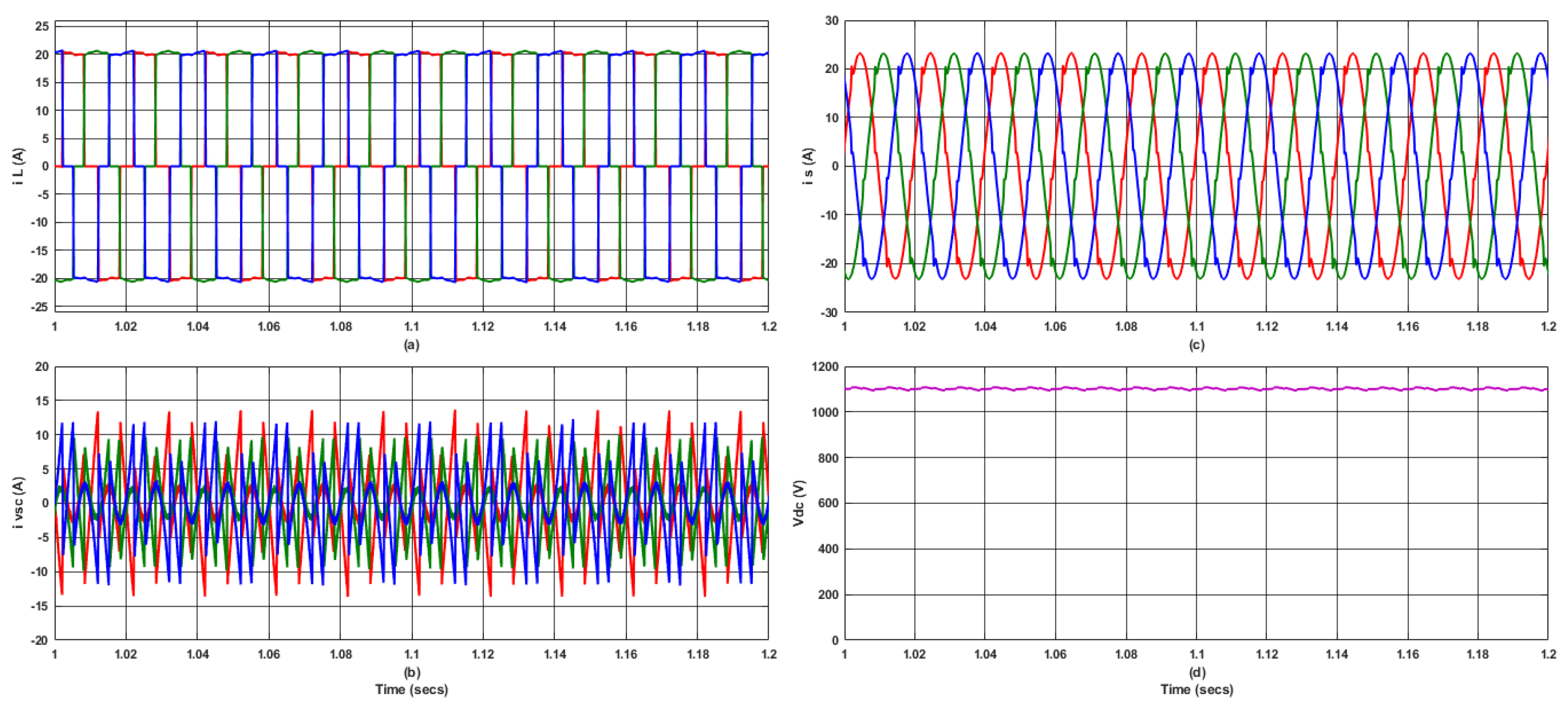
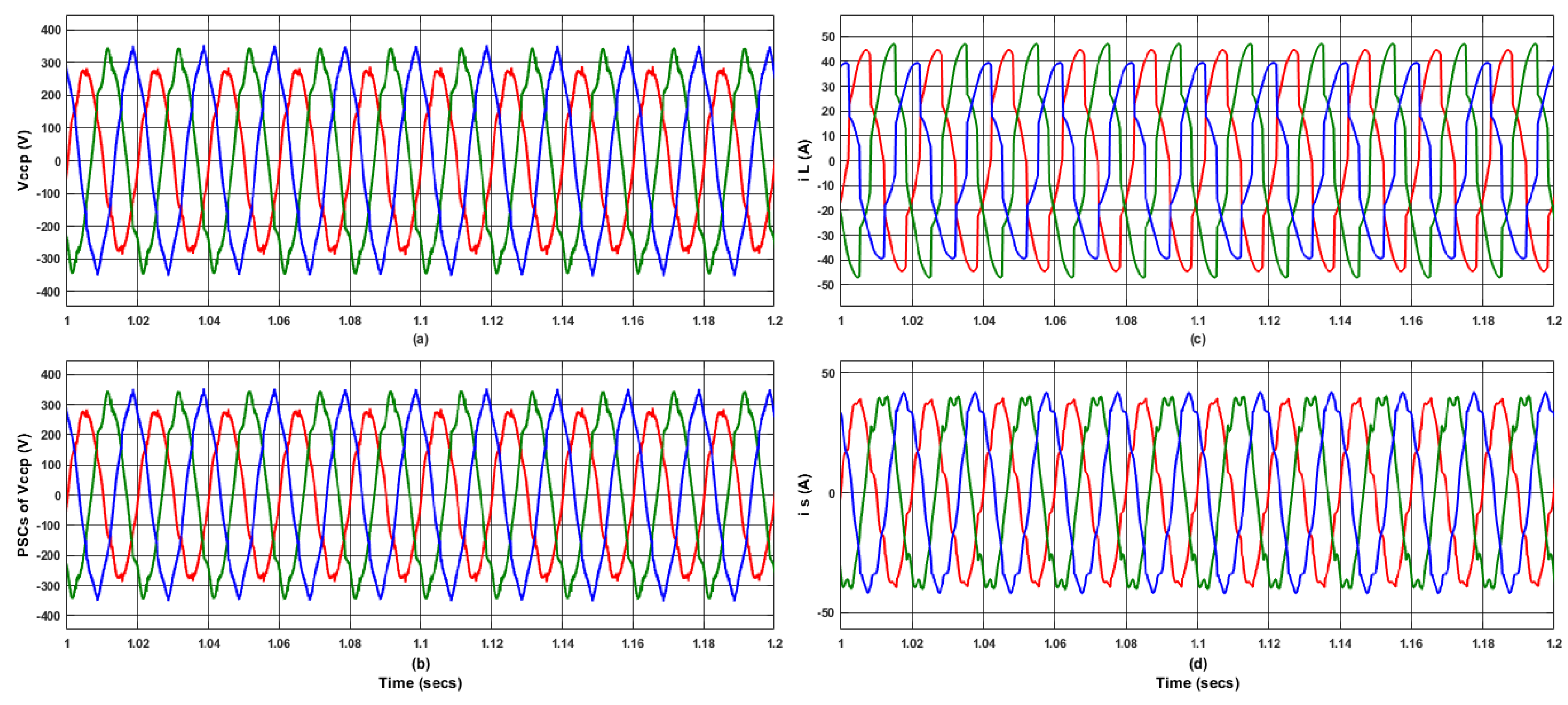
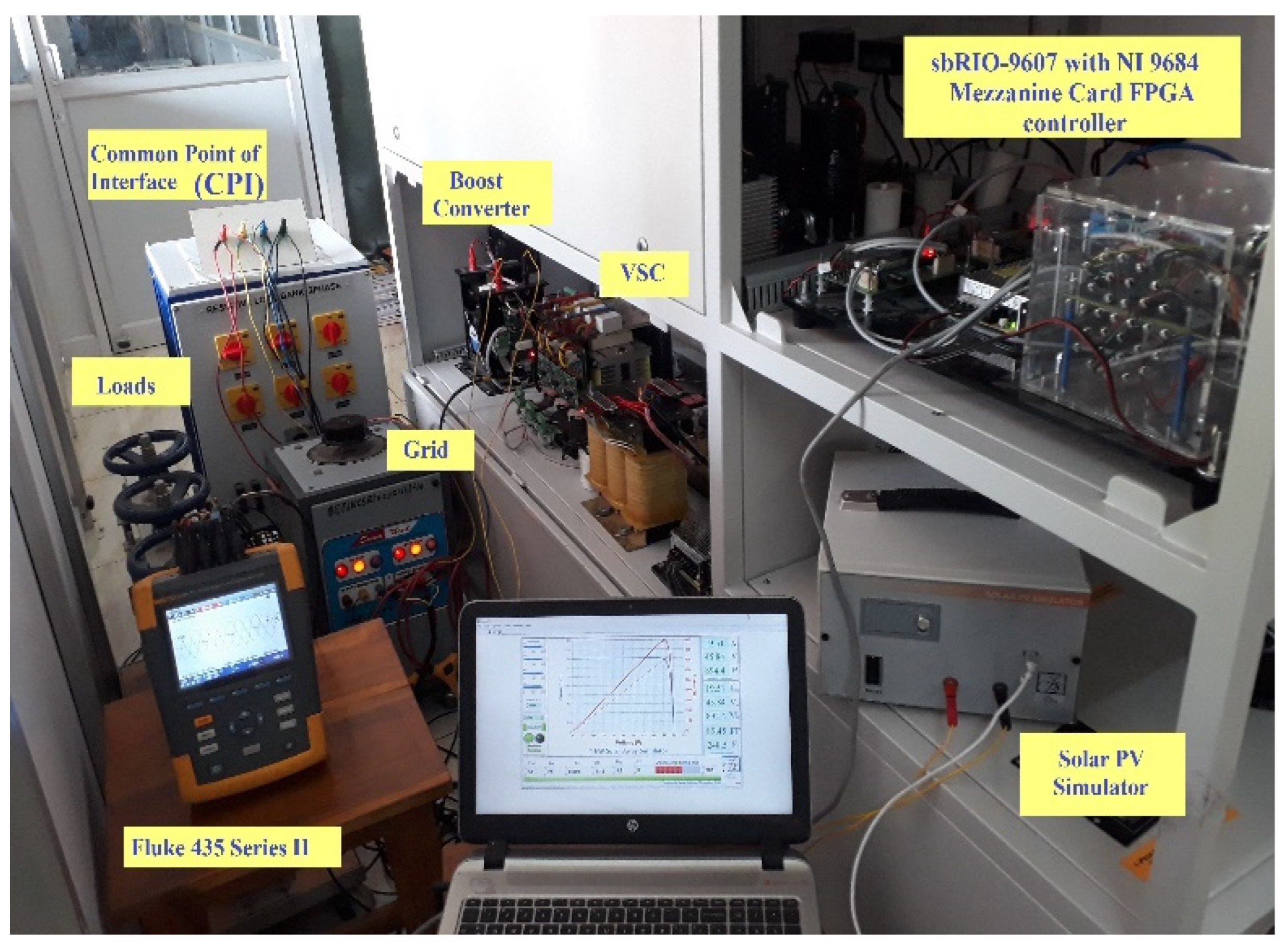
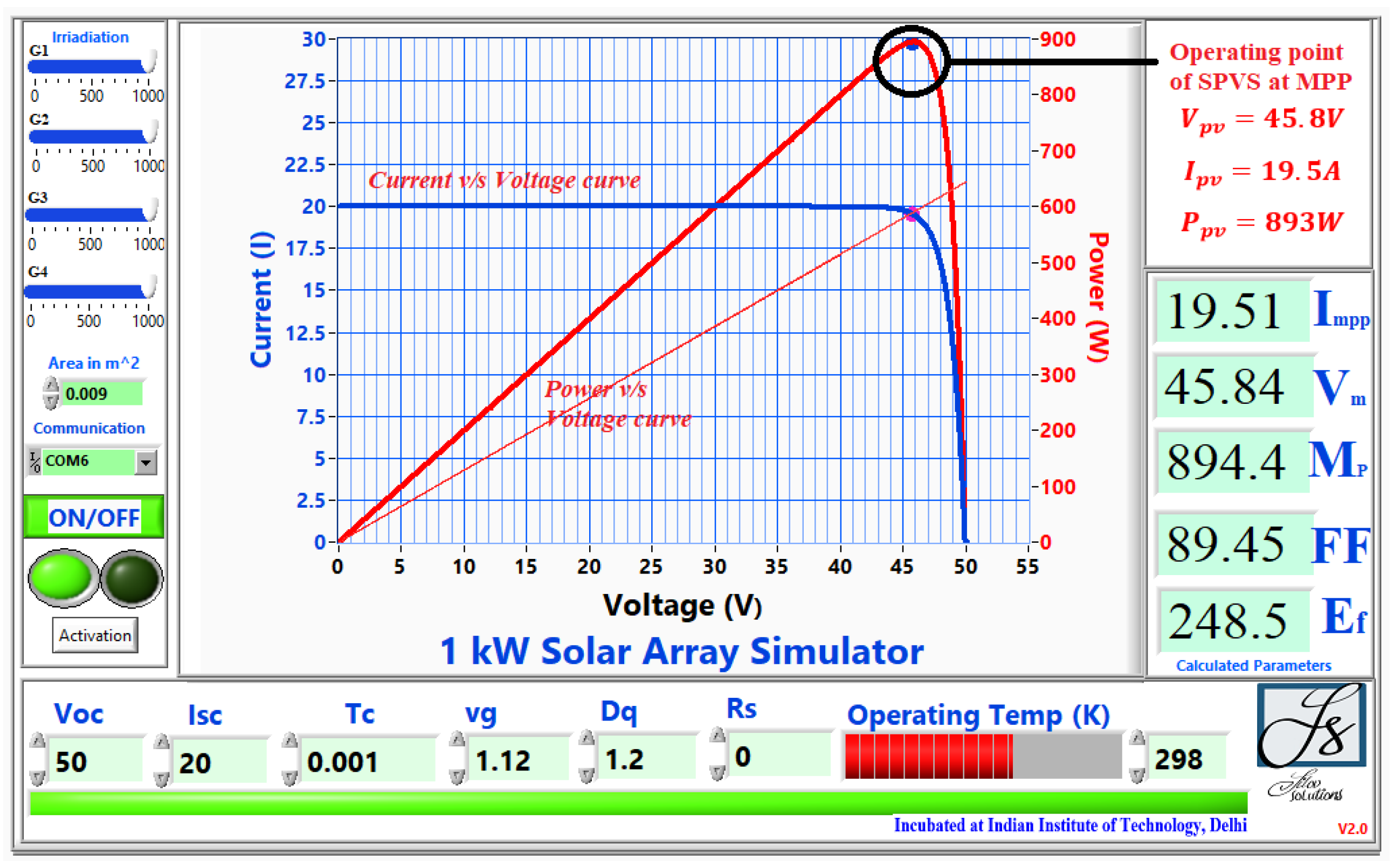
5. Experimental Studies

Figure 23 illustrates a laboratory test prototype for the proposed SPVS linked to a polluted grid through VSC (the test prototype details are mentioned in the Appendix A). Hall effect-based current/voltage sensors (LA-25P, LV-25P) were utilized during measurement. The values obtained from the sensors were analysed using the NI’s FPGA controller (9684 Mezzanine Card integrated sbRIO-9607) for generating gate pulses. The monitoring of all operational variables was accomplished by Fluke 435 series-II.

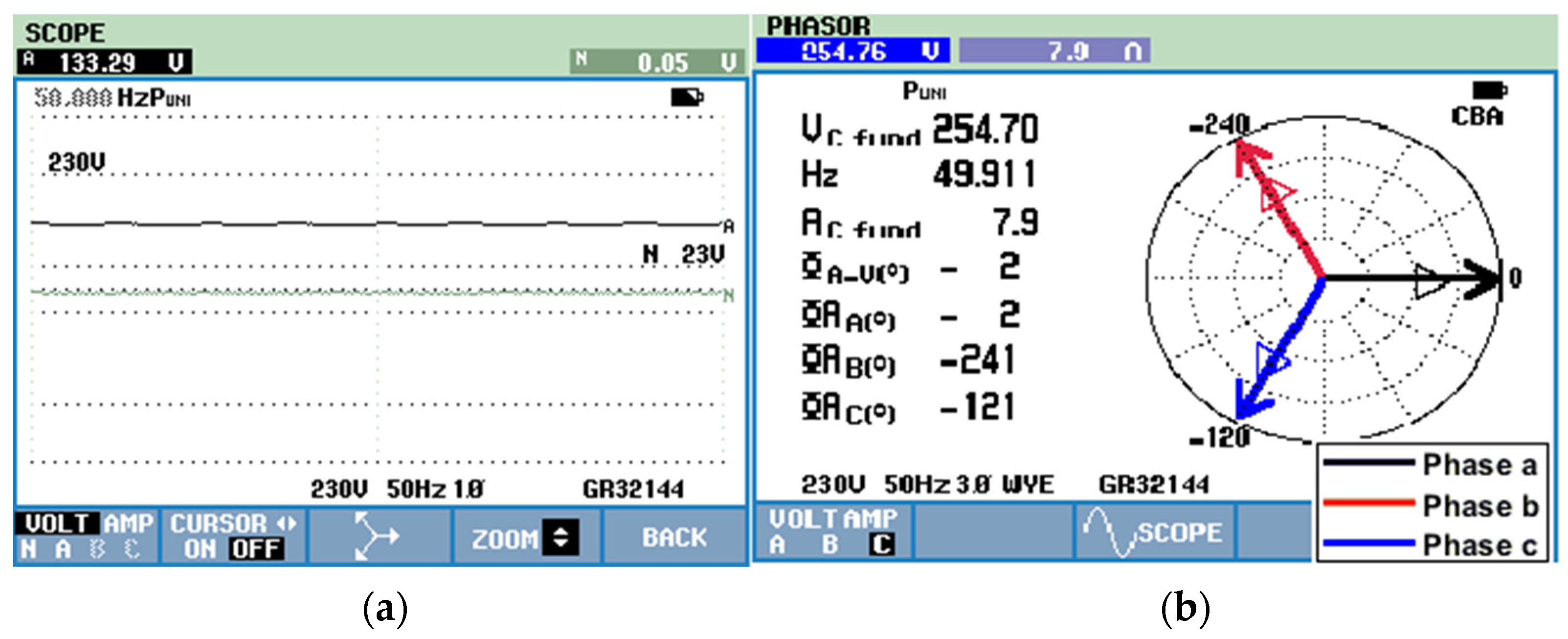
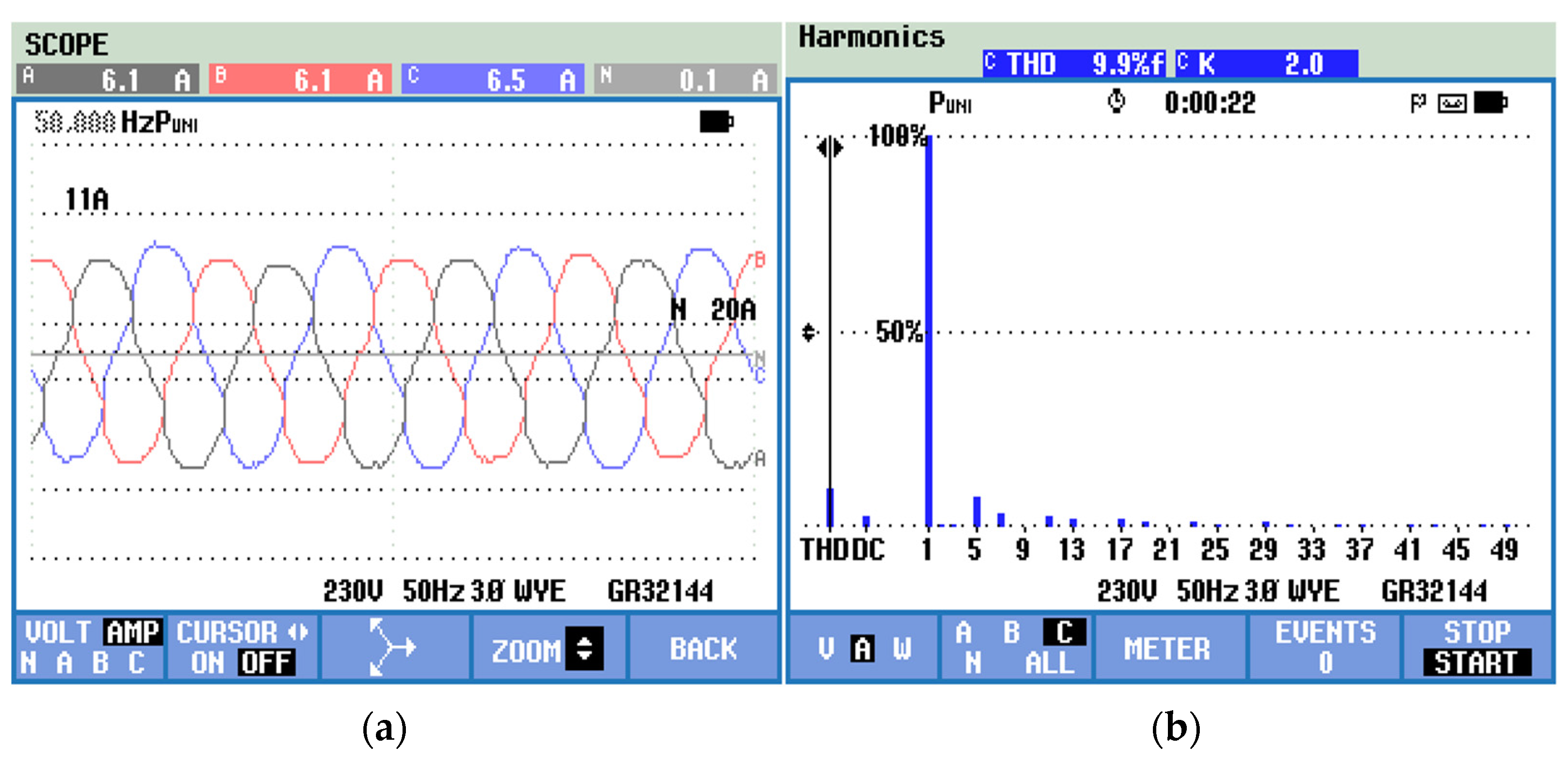
5.1. Response at SPV Hours

Here, the capability of the MVF-DEANF-PLL control method in the test prototype was investigated under a stable G of 1000 W/m2. The solar PV panel utilized in this study was a 1 kW PV simulator (ecosense brand). The V o c   and   I s c of the SPV simulator were configured as 50 V and 20 A, respectively. Appendix A contains the MPP parameters of this system. Figure 24 depicts the control interface of the PV simulator. By Figure 24, the SPVS works at I p v = 19.5 A, V p v = 45.8 V, and P p v = 893 W approximately. Thus, the 99% MPP tracking efficiency provided by the FSSINC MPPT control is visible.
Figure 25a depicts the distorted/unbalanced CCP voltages ( V C C P ) caused by polluted grid circumstances. Figure 25b displays the harmonic spectrum of V C C P , wherein the THD was measured to be 6.4%. Here, an unbalance of approximately 0.15 p.u. was introduced in phase ‘a’ CCP voltage. The CCP voltages ( V C C P ) in phases a, b, and c were 196 V, 251 V, and 247 V, respectively.
The non-linear/imbalanced load current ( i L a b c ) is illustrated in Figure 26a. In a contaminated grid scenario, Figure 26b illustrates the harmonic spectrum of i L a , which had a THD of about 13.2%. The load’s currents flowing through phases a, b, and c were measured to be 5.9 A, 7.6 A, and 7.8 A, respectively.
Figure 27a depicts the balanced/sinusoidal utility current ( i s a b c ) of 6.7 A even under distorted load current. The supply current ( i s a ) THD was approximately 3.9%, as depicted in Figure 27b. The accuracy of the MVF-DEANF-PLL methodology is clear, as the utility current’s ( i s a b c ) THD remained below the limitations of the IEEE-519 standard [25]. The laboratory arrangement of the SPVS with Widrow Hoff control exhibited a THD of around 4.06% in the utility current, as documented in the available literature [28]. The effectiveness of the proposed control in PQ issue alleviation exceeds that of the Widrow Hoff control.

5.2. Response at Non-SPV Hours

The capability of the proposed control approach in the test prototype was examined in this investigation during non-SPV hours.
The linear/balanced utility current ( i s a b c ) during non-SPV hours is illustrated in Figure 28a,b, together with the associated harmonic spectrum. The THD of the supply’s current ( i s a b c ) appeared to be around 3.7%. Due to the absence of SPV power production, the utility supply currents experienced an increase from 6.7 A to approximately 7.5 A to fulfil the whole of the load’s demand. The laboratory setup of the mixed LMS-LMF controller demonstrated a THD of approximately 4.1% in the utility current as reported in the existing literature [29]. The suggested MVF-DEANF-PLL control demonstrates greater effectiveness in mitigating harmonics and improving PQ at the CCP as compared to the integrated LMS-LMF controller. Figure 29a illustrates the efficacy of the FSSINC MPPT approach in maintaining the V d c close to the desired V d c * value of 130 V. The MVF-DEANF-PLL control method efficiently retained UPF operation by keeping the source current and supply voltage in phase, as depicted in Figure 29b.

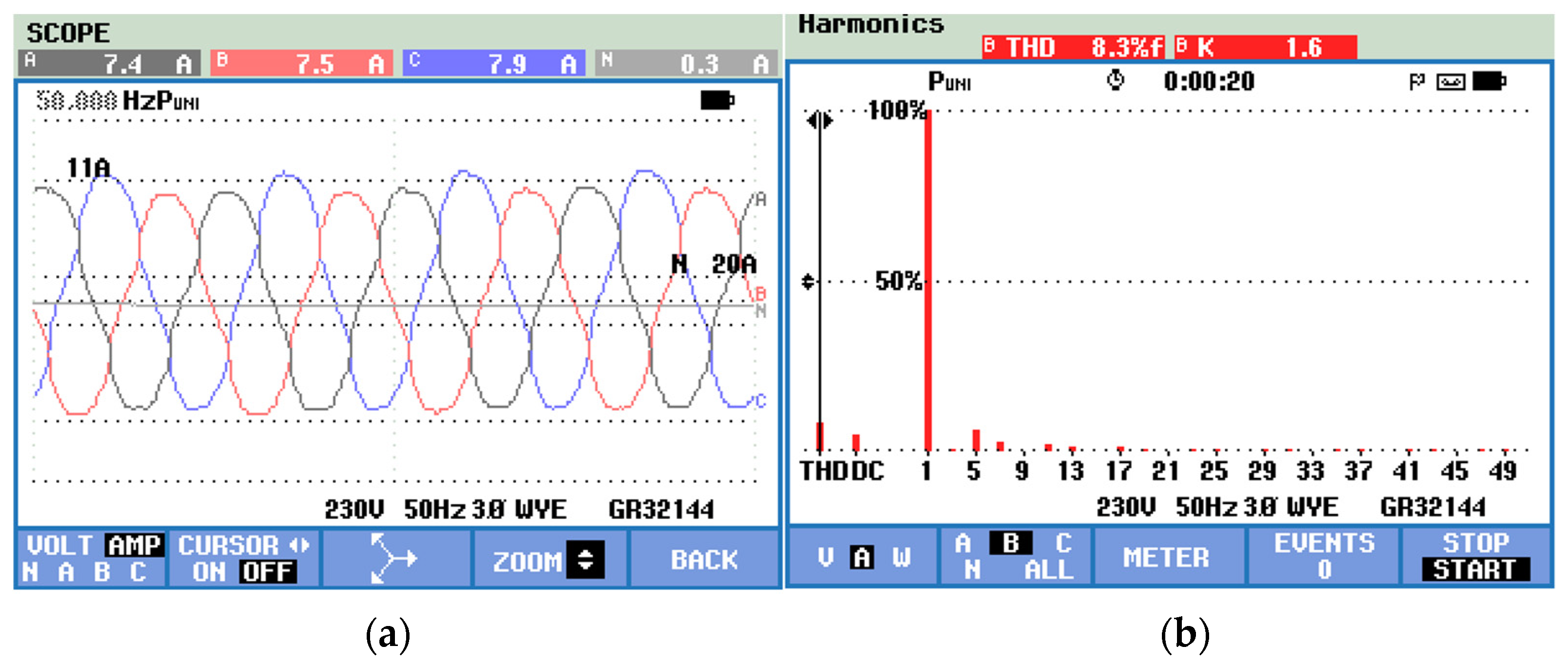
5.3. Response with Conventional SRF-PLL

In this case, the conventional SRF-PLL control method’s effectiveness was investigated under both SPV and non-SPV hours. Also, the experimental performance of the proposed control approach was compared with the conventional SRF-PLL-based control method.
Figure 30a depicts the utility current ( i s a b c ) in the conventional SRF-PLL control approach during SPV hours. In a contaminated grid scenario, Figure 30b illustrates the harmonic spectrum of i s b , which had a THD of about 9.9%. Figure 31a,b illustrates i s a b c during non-SPV hours, along with a harmonic spectrum of i s b , specifically THD of 8.3%. The SRF-PLL control failed to improve PQ indices at CCP under a polluted grid scenario. Hence, the SRF-PLL control is also not feasible for sources that are imbalanced/distorted.
Table 2 compares the experimental performance of the MVF-DEANF-PLL control strategy with the conventional SRF-PLL control scheme. Under a polluted utility supply scenario, it was observed that the SRF-PLL control approach failed to extract PSCs from the V C C P , resulting in an imbalanced supply current ( i s a b c ) distortion. The utility supply current ( i s a b c ) had a THD of 9.9% and 8.3% during SPV and non-SPV hours, respectively. However, the proposed control strategy offered much better source current with a THD of 2.5% and 2.2% during SPV and non-SPV hours, respectively.

6. Conclusions

By using MVF-DEANF-PLL control, the performance of the grid-integrated SPVS was examined under a polluted grid, an imbalanced load, and different solar irradiation levels. The FSSINC MPPT algorithm operated the SPVS at MPP excellently, and had 99% tracking efficiency. The SPV power extracted was fed to the load and utility supply by the VSC. Even in the case of an abnormal grid voltage circumstance, the MVF-DEANF-PLL control effectively obtained the PSCs of unbalanced/non-linear load currents and distorted grid voltages. The suggested control method demonstrates a significant reduction in the THD of CCP voltage PSCs. Specifically, the PSCs THD was reduced to 0.34%, which is notably lower compared to the 6.29% obtained with the traditional approach. The suggested control’s effectiveness in reactive power compensation, harmonics alleviation, UPF operation, and load balancing during SPV and non-SPV hours has been demonstrated by the simulation results. During the SPV hours of operation, the supply current exhibited a balanced/sinusoidal waveform, characterized by a THD of 3.25%. This remained valid despite the presence of a non-linear load’s current with a THD of 15.15%. During periods of non-SPV hours, the THD of the supply current was seen to be 2.11%, which is significantly lower compared to the THD of 8.54% observed in traditional control approaches. In both steady-state and dynamic conditions, satisfactory results were obtained in comparison with the conventional SRF-PLL-based control approach. The experimental study provides evidence supporting the efficacy of the suggested control method, which provides a balanced/sinusoidal supply current with a THD of around 2.5% in comparison with traditional control approaches exhibiting a THD of 9.9%. The test prototype’s experimental study results also complied with the IEEE-519 standard [25].

Author Contributions

Conceptualization, Methodology and Validation, B.M.; Supervision, S.S.; Project Administration, N.C. All authors have read and agreed to the published version of the manuscript.

Funding

This research received no external funding.

Institutional Review Board Statement

Not applicable.

Informed Consent Statement

Not applicable.

Data Availability Statement

The data presented in this study are available from the corresponding author upon reasonable request.

Conflicts of Interest

The authors declare no conflict of interest.

Nomenclature

SymbolsDefinition
VpvPV voltage (V)
Vpv*Reference PV voltage (V)
VmpVoltage at the MPP point (V)
VdcDC link voltage (V)
α*Duty ratio of boost converter
va, vb, vcCCP voltages at Phase a, b, and c (V)
vα, vβαβ components of CCP voltages
vd, vqdq components of CCP voltages
ωCentre frequency (rad/sec)
vα1, vβ1MVF’s filtered output in αβ frame
vα+, vβ+FFPS voltage components in αβ frame
vd+, vq+FFPS voltage components in dq frame
va+, vb+, vc+PSCs of CCP voltages
ua, ub, ucUnit templates

Appendix A

ParametersSimulation StudiesExperimental Studies
Supply system3-phase, 400 V (L-L), 50 Hz 3-phase, 400 V (L-L), 50 Hz
Unbalanced linear load Z L a = 9 Ω + j6.28 Ω
Z L b = 7 Ω + j9.42 Ω
Z L a = 11 Ω + j12.6 Ω
Z L a = 96 Ω + j3.77 Ω
Z L b = 51 Ω + j7.54 Ω
Z L a = 51 Ω + j11.3 Ω
Ripple filter R f = 5 Ω,
C f = 47 μF
R f = 5 Ω,
C f = 10 μF
Non-linear loadRL load with a diode bridge rectifier (3-phase)
R = 25   Ω ,   L = 120 mH
RL load with a diode bridge rectifier (3-phase)
R = 175   Ω ,   L = 24 mH
DC-link voltage reference V d c * = 1100 V V d c * = 130 V
DC link capacitor C 1 = C 2 = 1600 μF C 1 = C 2 = 3300 μF
Gain details for the PI controller K P = 0.6 ,   K I = 2.5 K P = 0.9 ,   K I = 1.4
Solar PV system V o c = 1207   V ,   I s c = 7.97   A ,   V m p = 966.9   V ,   I m p = 7.47   A ,   P m p = 7.22 kW V o c = 50   V ,   I s c = 20   A ,   V m p = 45.84   V ,   I m p = 19.51   A ,   P m p = 894.4 W
Hysteresis band ± 0.1 A ± 0.1 A
Interfacing inductor L f = 10 mH L f = 3 mH

References

  1. Bharatee, A.; Ray, P.K.; Ghosh, A. A Power Management Scheme for Grid-connected PV Integrated with Hybrid Energy Storage System. J. Mod. Power Syst. Clean Energy 2022, 10, 954–963. [Google Scholar] [CrossRef]
  2. Yildirim, M.A.; Nowak-Oclon, M. Modified Maximum Power Point Tracking Algorithm under Time-Varying Solar Irradiation. Energies 2020, 13, 6722. [Google Scholar] [CrossRef]
  3. Murshid, S.; Singh, B. Double Stage Solar PV Array Fed Water Pump Driven by Permanent Magnet Synchronous Motor. IEEE Trans. Ind. Appl. 2021, 57, 1736–1745. [Google Scholar] [CrossRef]
  4. Viloria-Porto, J.; Robles-Algarín, C.; Restrepo-Leal, D. A Novel Approach for an MPPT Controller Based on the ADALINE Network Trained with the RTRL Algorithm. Energies 2018, 11, 3407. [Google Scholar] [CrossRef]
  5. Pandey, A.K.; Singh, V.; Jain, S. Maximum Power Point Tracking Algorithm Based on Fuzzy Logic Control Using P-V and I-V Characteristics for PV Array. IEEE Trans. Ind. Appl. 2023, 59, 4572–4583. [Google Scholar] [CrossRef]
  6. Rani, V.; Mahela, O.P.; Doraya, H. Power Quality Improvement in the Distribution Network with Solar Energy Penetration Using Distribution Static Compensator. In Proceedings of the 2018 International Conference on Computing, Power and Communication Technologies (GUCON), Greater Noida, India, 28–29 September 2018; pp. 148–154. [Google Scholar]
  7. Badoni, M.; Singh, A.; Pandey, S.; Singh, B. Fractional-Order Notch Filter for Grid-Connected Solar PV System with Power Quality Improvement. IEEE Trans. Ind. Electron. 2022, 69, 429–439. [Google Scholar] [CrossRef]
  8. Bighash, E.Z.; Sadeghzadeh, S.M.; Ebrahimzadeh, E.; Blaabjerg, F. Adaptive-Harmonic Compensation in Residential Distribution Grid by Roof-Top PV Systems. IEEE J. Emerg. Sel. Top. Power Electron. 2018, 6, 2098–2108. [Google Scholar] [CrossRef]
  9. Harirchi, F.; Simoes, M.G. Enhanced Instantaneous Power Theory Decomposition for Power Quality Smart Converter Applications. IEEE Trans. Power Electron. 2018, 33, 9344–9359. [Google Scholar] [CrossRef]
  10. Kumar, A.; Kumar, P. Power Quality Improvement for Grid-connected PV System Based on Distribution Static Compensator with Fuzzy Logic Controller and UVT/ADALINE-based Least Mean Square Controller. J. Mod. Power Syst. Clean Energy 2021, 9, 1289–1299. [Google Scholar] [CrossRef]
  11. Singh, A.K.; Hussain, I.; Singh, B. Double-Stage Three-Phase Grid-Integrated Solar PV System with Fast Zero Attracting Normalized Least Mean Fourth Based Adaptive Control. IEEE Trans. Ind. Electron. 2018, 65, 3921–3931. [Google Scholar] [CrossRef]
  12. Nazir, F.U.; Kumar, N.; Pal, B.C.; Singh, B.; Panigrahi, B.K. Enhanced SOGI Controller for Weak Grid Integrated Solar PV System. IEEE Trans. Energy Convers. 2020, 35, 1208–1217. [Google Scholar] [CrossRef]
  13. Pathak, G.; Mohanty, D.; Dwivedi, S.K.; Singh, B.; Panigrahi, B.K. Implementation of MVF-Based Control Technique for 3-Φ Distribution Static Compensator. J. Inst. Eng. (India) Ser. B 2019, 100, 589–597. [Google Scholar] [CrossRef]
  14. Rajkumar, K.; Parthiban, P. Grid voltage detection method based on a novel adaptive notch filter for control of transformerless dynamic voltage restorer. In Proceedings of the 2020 IEEE First International Conference on Smart Technologies for Power, Energy and Control (STPEC), Nagpur, India, 25–26 September 2020; pp. 1–6. [Google Scholar]
  15. Nguyen, A.T.; Lee, D.C. Advanced Grid Synchronization Scheme Based on Dual eSOGI-FLL for Grid-Feeding Converters. IEEE Trans. Power Electron. 2022, 37, 7218–7229. [Google Scholar] [CrossRef]
  16. Xin, Z.; Zhao, R.; Mattavelli, P.; Loh, P.C.; Blaabjerg, F. Re-Investigation of Generalized Integrator Based Filters From a First-Order-System Perspective. IEEE Access 2016, 4, 7131–7144. [Google Scholar] [CrossRef]
  17. Chaudhari, D.S.; Patil, K.R. DSOGI Based Performance Evaluation of D-STATCOM for Load Harmonic Compensation in Three-Phase Three-wire Polluted Utility System. In Proceedings of the 2020 IEEE International Conference for Innovation in Technology (INOCON), Bangluru, India, 6–8 November 2020; pp. 1–7. [Google Scholar]
  18. Chuang, M.T.; Liu, Y.H.; Ye, S.P. A Novel Variable Step Size Incremental Conductance Method with an Adaptive Scaling Factor. Appl. Sci. 2020, 10, 5214. [Google Scholar] [CrossRef]
  19. Venkatramanan, D.; John, V. Dynamic Phasor Modeling and Stability Analysis of SRF-PLL-Based Grid-Tie Inverter Under Islanded Conditions. IEEE Trans. Ind. Appl. 2020, 56, 1953–1965. [Google Scholar] [CrossRef]
  20. Singh, R.; Singh, A. Performance Evaluation of Three-Phase Unified Power Quality Conditioner controlled using SRF. In Proceedings of the 2021 4th International Conference on Recent Developments in Control, Automation & Power Engineering (RDCAPE), Noida, India, 7–8 October 2021; pp. 486–491. [Google Scholar]
  21. Choukri Benhabib, M.; Saadate, S. A new robust experimentally validated phase-looked loop for power electronic control. EPE J. 2005, 15, 36–48. [Google Scholar] [CrossRef]
  22. Daou, N.; Khatounian, F. A combined phase locked loop technique for grid synchronization of power converters under highly distorted grid conditions. In Proceedings of the 2016 IEEE International Multidisciplinary Conference on Engineering Technology (IMCET), Beirut, Lebanon, 2–4 November 2016; pp. 108–114. [Google Scholar]
  23. Hui, N.; Luo, Z.; Feng, Y.; Han, X. A Novel Grid Synchronization Method Based on Hybrid Filter Under Distorted Voltage Conditions. IEEE Access 2020, 8, 65636–65648. [Google Scholar] [CrossRef]
  24. Chittora, P.; Singh, A.; Singh, M. Simple and efficient control of DSTATCOM in three-phase four-wire polluted grid system using MCCF-SOGI based controller. IET Gener. Transm. Distrib. 2018, 12, 1213–1222. [Google Scholar] [CrossRef]
  25. IEEE Std 519-1992; IEEE Recommended Practices and Requirements for Harmonic Control in Electrical Power Systems. IEEE: New York, NY, USA. [CrossRef]
  26. Shukl, P.; Singh, B. Recursive Digital Filter Based Control for Power Quality Improvement of Grid Tied Solar PV System. IEEE Trans. Ind. Appl. 2020, 56, 3412–3421. [Google Scholar] [CrossRef]
  27. Badoni, M.; Singh, A.; Singh, V.P.; Tripathi, R.N. Grid interfaced solar photovoltaic system using ZA-LMS based control algorithm. Electr. Power Syst. Res. 2018, 160, 261–272. [Google Scholar] [CrossRef]
  28. Modi, G.; Kumar, S.; Singh, B. Improved Widrow–Hoff Based Adaptive Control of Multiobjective PV-DSTATCOM System. IEEE Trans. Ind. Appl. 2020, 56, 1930–1939. [Google Scholar] [CrossRef]
  29. Srinivas, M.; Hussain, I.; Singh, B. Combined LMS–LMF-Based Control Algorithm of DSTATCOM for Power Quality Enhancement in Distribution System. IEEE Trans. Ind. Electron. 2016, 63, 4160–4168. [Google Scholar] [CrossRef]
Figure 1. Grid-integrated SPVS with MVF-DEANF-PLL control.
Sustainability 15 15487 g001
Figure 2. Structure of SRF-PLL.
Sustainability 15 15487 g002
Figure 3. MVF block framework.
Sustainability 15 15487 g003
Figure 4. Block model of EANF.
Sustainability 15 15487 g004
Figure 5. Block model of DEANF.
Sustainability 15 15487 g005
Figure 6. MVF-DEANF-PLL blocks.
Sustainability 15 15487 g006
Figure 7. MVF-DEANF-PLL for load current.
Sustainability 15 15487 g007
Figure 8. SPVS parameters V p v ,   I p v ,   P p v ,   a n d   V d c at constant P p v .
Sustainability 15 15487 g008
Figure 9. (a) CCP Voltages ( V c c p ), (b) PSCs of V c c p , (c) v α   + ,   v β   + ,   v d   +   and   v q   + , (d) unit templates.
Sustainability 15 15487 g009
Figure 10. System currents i L a b c ,   i v s c ,   i g a b c at constant P p v .
Sustainability 15 15487 g010
Figure 11. System powers PL, Pvsc, Ps, QL, Qvsc, Qs at constant P p v .
Sustainability 15 15487 g011
Figure 12. Harmonic Spectra (a) Vccpa, (b) i L a , (c) i s a .
Sustainability 15 15487 g012aSustainability 15 15487 g012b
Figure 13. Dynamics of system response— G , P p v ,   P v s c ,   P g ,   V d c , i L a b c ,   i v s c ,   a n d   i g a b c .
Sustainability 15 15487 g013
Figure 14. System currents at non-SPV hours iLabc, ivsc, isabc.
Sustainability 15 15487 g014
Figure 15. System behaviour at non-SPV hours (a) Vccp, (b) PSCs of V c c p , (c) V d c , (d) PSC of V c c p a a n d   i s a .
Sustainability 15 15487 g015
Figure 16. Harmonic Spectra (a) Vccp (b) isa.
Sustainability 15 15487 g016
Figure 17. Dynamics of system response (a) iLabc, (b) i v s c , (c) i s a b c ,   (d) V d c at non-SPV hours.
Sustainability 15 15487 g017
Figure 18. System behaviour (a) iLabc, (b) ivsc, (c) i s a b c , (d) V d c under purely non-linear load.
Sustainability 15 15487 g018
Figure 19. Harmonic spectra (a) iLa (b) i s a .
Sustainability 15 15487 g019
Figure 20. SRF-PLL system responses (a) Vccp, (b) PSCs of V c c p (c) iLabc, (d) i s a b c at non-SPV hours.
Sustainability 15 15487 g020
Figure 21. Harmonic spectra of isa.
Sustainability 15 15487 g021
Figure 22. Comparison of PSCs of VCCP.
Sustainability 15 15487 g022
Figure 23. Test prototype.
Sustainability 15 15487 g023
Figure 24. Proposed system’s MPPT.
Sustainability 15 15487 g024
Figure 25. (a) V C C P , (b) VCCP harmonic spectrum.
Sustainability 15 15487 g025
Figure 26. (a) i L a b c , (b) i L a harmonic spectrum.
Sustainability 15 15487 g026
Figure 27. (a) i s a b c , (b) i s a b c harmonic spectrum.
Sustainability 15 15487 g027
Figure 28. (a) i s a b c , (b) i s a b c harmonic spectrum at non-SPV hours.
Sustainability 15 15487 g028
Figure 29. (a) V d c , (b) Phasor diagram.
Sustainability 15 15487 g029
Figure 30. (a) i s a b c , (b) i s c harmonic spectrum at SPV hours.
Sustainability 15 15487 g030
Figure 31. (a) i s a b c , (b) isb harmonic spectrum at non-SPV hours.
Sustainability 15 15487 g031
Table 1. Simulated performance comparison between the proposed method and the conventional SRF-PLL approach.
System Parameters Conventional SRF-PLL Control (THD)Proposed MVF-DEANF-PLL
Control (THD)
V C C P 6.30%6.30%
PSCs of VCCP 6.29%0.34%
i L a 15.15%15.15%
i s a Non-SPV hours—8.54%Non-SPV hours—2.11%
Table 2. Experimental performance comparison between the proposed method and the conventional SRF-PLL approach.
System Parameters Conventional SRF-PLL Control (THD)Proposed MVF-DEANF-PLL
Control (THD)
V C C P 6.4%6.4%
i L 13.2%13.2%
i s SPV hours—9.9%
Non-SPV hours—8.3%
SPV hours—2.5%
Non-SPV hours—2.2%
Disclaimer/Publisher’s Note: The statements, opinions and data contained in all publications are solely those of the individual author(s) and contributor(s) and not of MDPI and/or the editor(s). MDPI and/or the editor(s) disclaim responsibility for any injury to people or property resulting from any ideas, methods, instructions or products referred to in the content.

