Abstract
The rising demand for stable power supply in distribution systems has increased the importance of reliable supply. Thus, a networked distribution system (NDS) linked with individual lines is being adopted, gradually replacing the radial distribution system (RDS) currently applied to most distribution systems. Implementing the NDS can lead to various improvements in factors such as line utilization rate, acceptance rates of distributed power, and terminal voltages, while mitigating line losses. However, compared with the RDS, the NDS can experience bidirectional fault currents owing to its interconnected lines, thereby hindering protection coordination, which must be addressed before the NDS can be implemented in real-world power systems. Due to the characteristics of NDS, the reverse fault current is relatively small. However, this phenomenon becomes more severe when the high impedance fault (HIF) occurs. In this paper, the malfunction of protective devices during the HIF is directly verified and analyzed in the NDS. As a result, when the HIF occurs, the issue of the reverse protective device malfunctioning worsens because of a reduction in fault current and a failure in direction detection. To solve this issue, this work proposes a communication-based protection algorithm. Through the comparative verification of the proposed algorithm and the conventional protection method, protection coordination can be secured in the case of an HIF without new devices. It must be highlighted that the proposed method does not affect the settings of the protective device and provides a cost-effective and efficient solution since this algorithm is added independently to the existing relay.
1. Introduction
1.1. Background
In recent years, there has been a surge of interest in the climate change challenges facing the world. Numerous global policies are being enforced to address problems related to climate change, rapidly shifting from traditional fossil fuels to renewable energy for distributed power generation. The expanding connection of distributed generators (DGs) and power electronic facilities, including power converters, into distribution systems is driving significant changes in modern distribution systems. The demand for DGs is rapidly increasing over time because they are an alternative power source and provide a solution to reducing CO2 emissions [1]. However, when the penetration of such sources exceeds the hosting capacity (HC) of the distribution system, it may lead to various problems. These can include overvoltage, feeder end overload, protective device malfunction, and other operational issues [2,3,4]. To increase the integration of DGs in the RDS, which is currently applied to most distribution systems, without experiencing operational problems, the HC should be increased through optimization or feeder reinforcement [3,5]. However, since reinforcing the feeder to increase HC in the RDS is expected to be costly, interconnecting each feeder is considered as a solution. This approach can reduce overvoltage caused by the integration of DGs and enable economical system operation owing to reduced line losses and voltage drops. In addition, it allows stable operation even at high penetration levels of DGs and is expected to enhance power distribution [6,7,8].
Furthermore, the connection of large industrial loads, such as semiconductor factories and data centers, to the distribution system has been increasing recently. As a result, the demand for high power supply reliability is growing, as these loads can result in significant economic losses even with short outages [9,10]. Therefore, the method of interconnecting the feeder makes it possible to supply power to the load from the load side, even in situations where supply from the source side is impossible. This method can be a solution for improving power supply reliability. Depending on the connection level, a distribution network topology connecting two feeders defines a closed-loop system, and topologies with more connected feeders establish meshed or networked systems [11]. Compared to the RDS, a closed-loop system offers many advantages, such as improved supply reliability. However, its economic benefits are diminished due to operations at lower utilization rates as a preparation for fault conditions. Alternatively, by increasing the number of connected feeders and establishing NDS, the utilization rate can be improved. This approach is currently being actively studied as a topology for future distribution systems and can improve rapidly changing distribution systems.
1.2. Literature Survey
1.2.1. Protection Coordination in Networked Distribution System
The transition from an RDS to an NDS yields distinct benefits. However, this transition to NDS also adds considerations of new issues in terms of operation and planning [7]. As a representative issue, since NDS has interconnected lines, an imbalance or fault in a single line can impact the entire system. Additionally, in an NDS, the risk of protection coordination failure is higher due to bidirectional fault current. This is because when a fault occurs in an NDS, protective devices must consider the magnitude and direction of the fault current. In other words, if a protective device fails to detect the direction of a fault, it can lead to the failure of protection coordination. To solve this problem, [12] proposes a direction detection method using a communication-based protection coordination scheme and a long short-term memory (LSTM) neural network. In particular, the issue of malfunctioning protective devices becomes more severe in NDS with DGs [13]. As a result, in an NDS with interconnected operations, advanced protection coordination and optimal settings for protective devices are required [14,15,16].
1.2.2. Component Introduction in Networked Distribution Systems and Protection Coordination Methods
In an NDS, using back-to-back converters to interconnect feeders, called soft open points or DC links, brings numerous benefits. These include improvements in voltage profile, load leveling, increased HC, and economic enhancements owing to reduced power losses [17,18,19,20,21]. Introducing soft open points, which allow bidirectional current control and prevent fault propagation, considerably contributes to the protection coordination of NDS [22]. Another new device for NDS is the superconducting fault-current limiter [23,24], which operates in an NDS during steady-state conditions and allows the transition to an RDS if a fault occurs. This device operates as a superconductor in steady-state conditions to form an NDS and reduce losses. During a fault, it has high resistance, reducing short-circuit current. It opens when a threshold is exceeded, allowing the protective devices used in RDS to be utilized. As a result, the superconducting fault-current limiter offers advantages in NDS during steady-state conditions. In the event of a fault, it can be flexibly converted to an RDS, effectively reducing the fault current to an RDS level. This device prevents the spread of faults and reduces circuit breaker replacement costs.
1.3. Contributions
This paper proposes protection logic for the relays implemented in an existing distribution system, enabling effective protection coordination for the NDS. The proposed method is evaluated under high impedance faults (HIFs). The contributions of this study are as follows:
- The fault current characteristics of NDS and existing protection coordination methods are described. In addition, the impact on protective devices is verified and analyzed through simulation of an HIF occurring in an NDS.
- In this paper, a protection algorithm is proposed for when an HIF occurs in NDS. This approach does not require new devices, such as BTB converters or superconducting fault-current limiters. The proposed algorithm is an economical solution as it only requires adding a protection algorithm to the existing relay.
- The proposed algorithm improves the operation speed of existing protective devices, even in HIF, and solves the problem of protective devices malfunctioning due to direction detection failure.
This paper proposes an equation that intuitively confirms the direction detection status of a directional overcurrent relay (DOCR) applied to an NDS when a fault occurs.
- The proposed method contributes to solving protective device malfunction due to the reversal of zero-sequence direction according to the time difference between the operation of two circuit breakers under a ground fault.
- As the proposed method operates independently of existing protection coordination, it does not affect the settings of existing protective devices.
The organization of this paper is as follows. Section 2 introduces the background of the protective device, HIF characteristics, and the proposed protection algorithm in NDS. In this section, formulas used in actual protective devices and a pickup current indicator that determines protective device operation are also included. Section 3 explains the simulation setup for the case study and verifies the proposed protection method. Finally, Section 4 provides some concluding remarks.
2. Theoretical Background and the Proposed Method
2.1. Protection Device Operation Characteristics and Indicators
2.1.1. Ratio between Fault and Pickup Currents
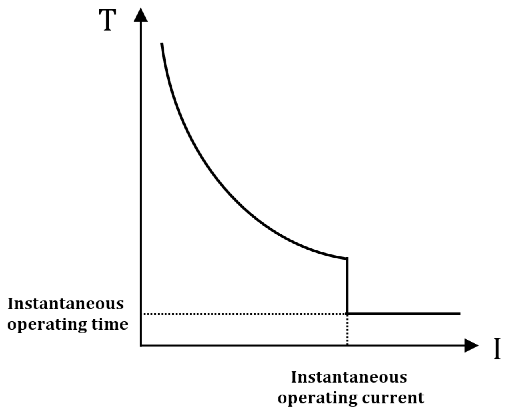
Relays implemented in a distribution system operate according to the time–current curve (TCC) characteristics given by Equation (1), whose variables are defined in Table 1 [25]. A typical TCC is shown in Figure 1. As the fault current increases, the operation time of the circuit breaker decreases. When the fault current exceeds the instantaneous operating current, the circuit breaker is instantaneously tripped, protecting the system.

Table 1.
The nomenclature in Equation (1).

Figure 1.
TCC characteristics.
The ratio between fault current () and pickup current () is defined as the plug setting multiplier [25]. In Korean distribution systems, the of the overcurrent ground relay is set between 70 A and 80 A under a ground fault, while the of the overcurrent relay is set at 400 A under a short-circuit fault. For a protective device to operate, must be greater than , thus requiring > 1. However, the fault resistance affects the fault current, and when the fault resistance is large (e.g., HIF), condition > 1 is not met, causing operational problems for the protective device. Thus, ratio ) is used as an indicator to determine the operation of the protective device.
2.1.2. Direction Detection Formula
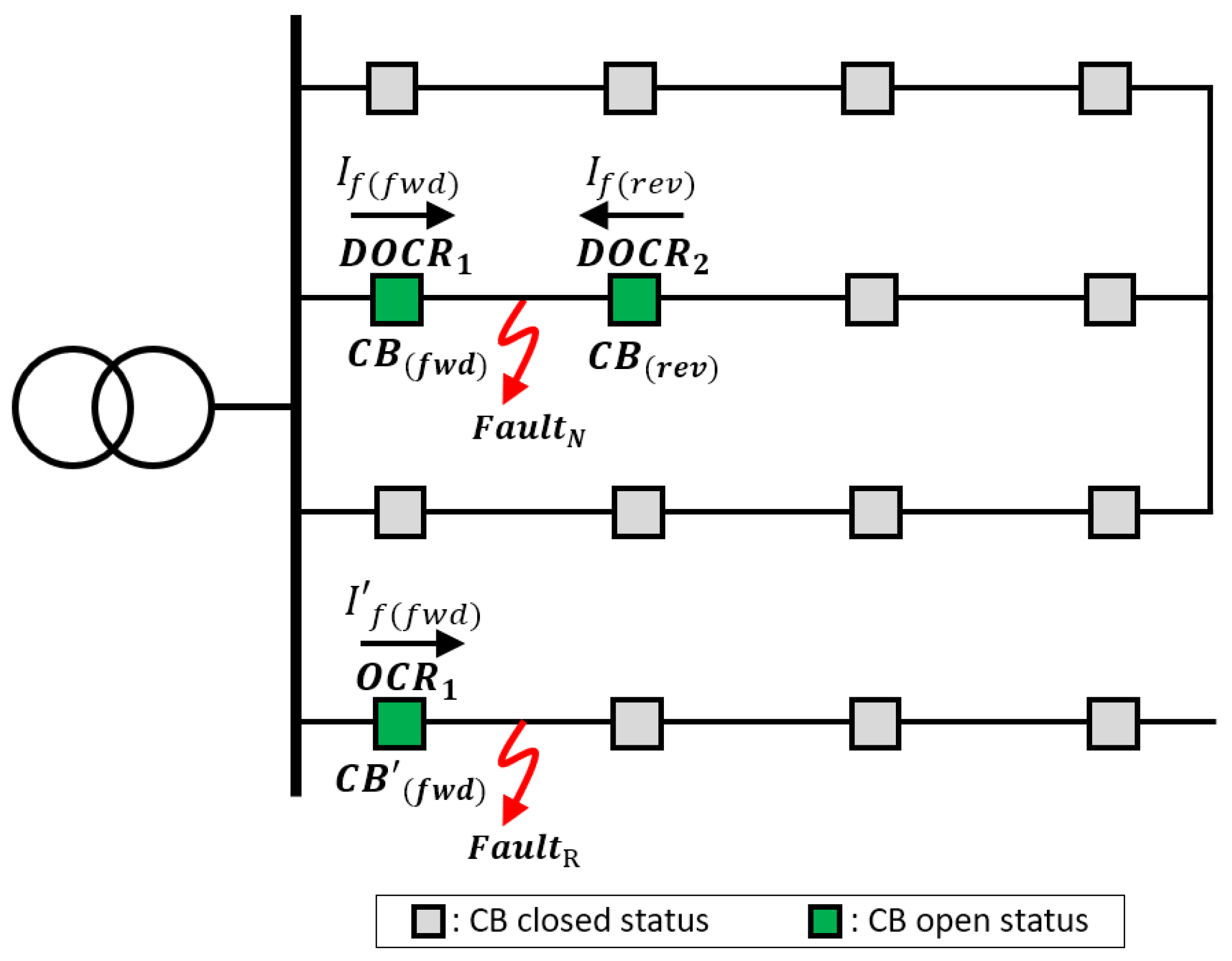
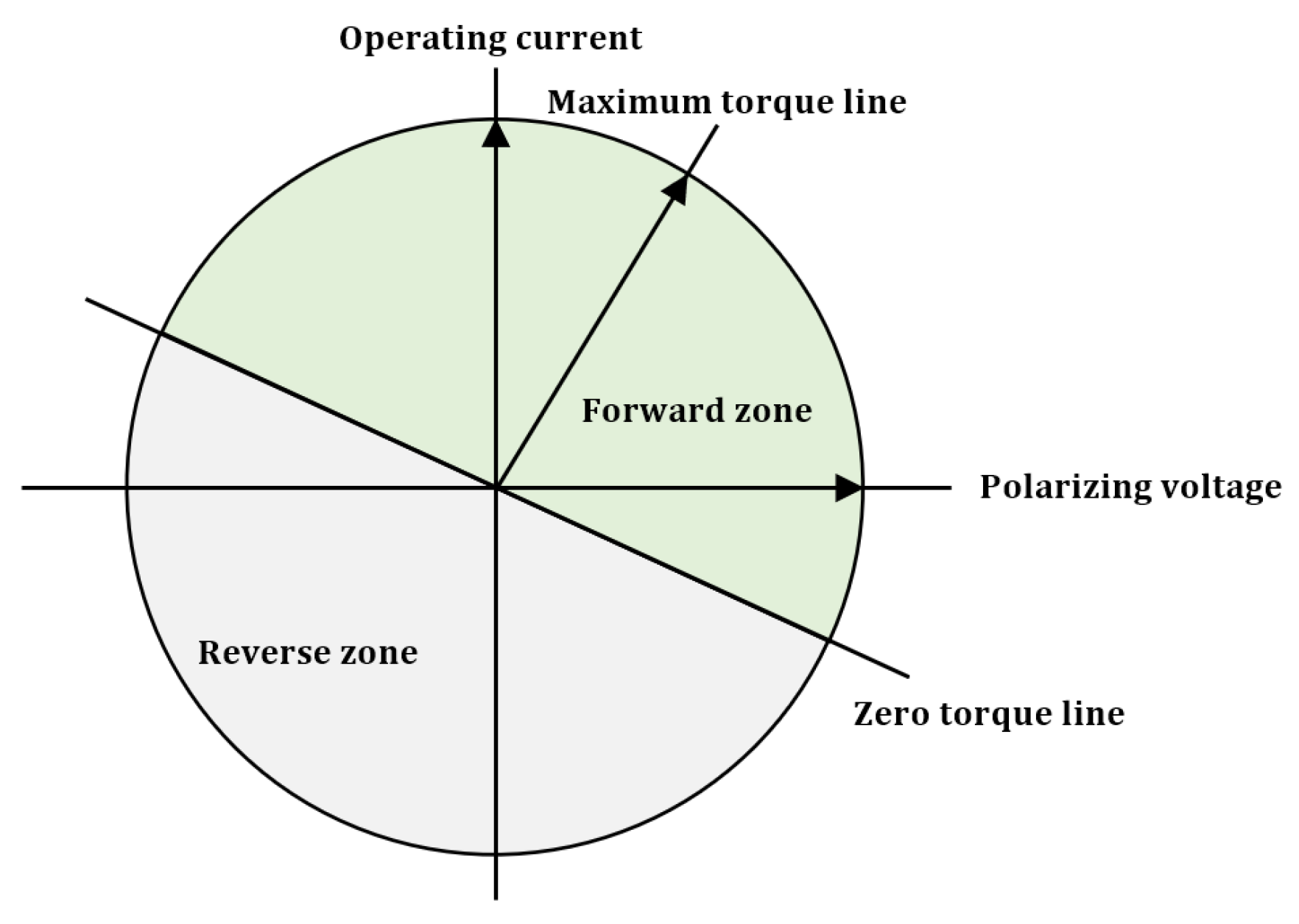
Figure 2 illustrates the protection coordination for RDS and NDS, where the nomenclatures are defined in Table 2. In an RDS, when a fault () occurs, the relay () operates the circuit breaker () based on the magnitude of the unidirectional fault current from the power supply to the load, thus achieving relatively simple protection coordination. On the other hand, under a fault () in an NDS, which is the test system in this study, bidirectional fault currents flow. In this paper, the fault current on the source side is defined as the forward fault current, while the fault current on the load side fault current is defined as the reverse fault current. Direction detection is essential to operate the protective devices in the test system, and at least two (forward and reverse ) must be installed. Equations (2) and (3) represent the direction detection equations applied in South Korea. A zero-sequence equation is applied under a ground fault, while a positive-sequence equation is applied under a short-circuit fault. When applying direction detection, one DOCR should be recognized as forward (+), and the other DOCR should be recognized as reverse (−) depending on the fault location. Equation (4) represents correct direction detection, while Equation (5) represents failed direction detection. The maximum torque angle (MTA) in these equations compensates for the protective device angle, such that the fault current maximizes sensitivity, as depicted in Figure 3.

Figure 2.
Protection coordination in RDS and NDS.
Table 2.
The nomenclature used in Figure 2.

Figure 3.
DOCR characteristics according to maximum torque angle. (green: forward zone, gray: reverse zone).
2.2. Fault Current Characteristic Analysis in NDS
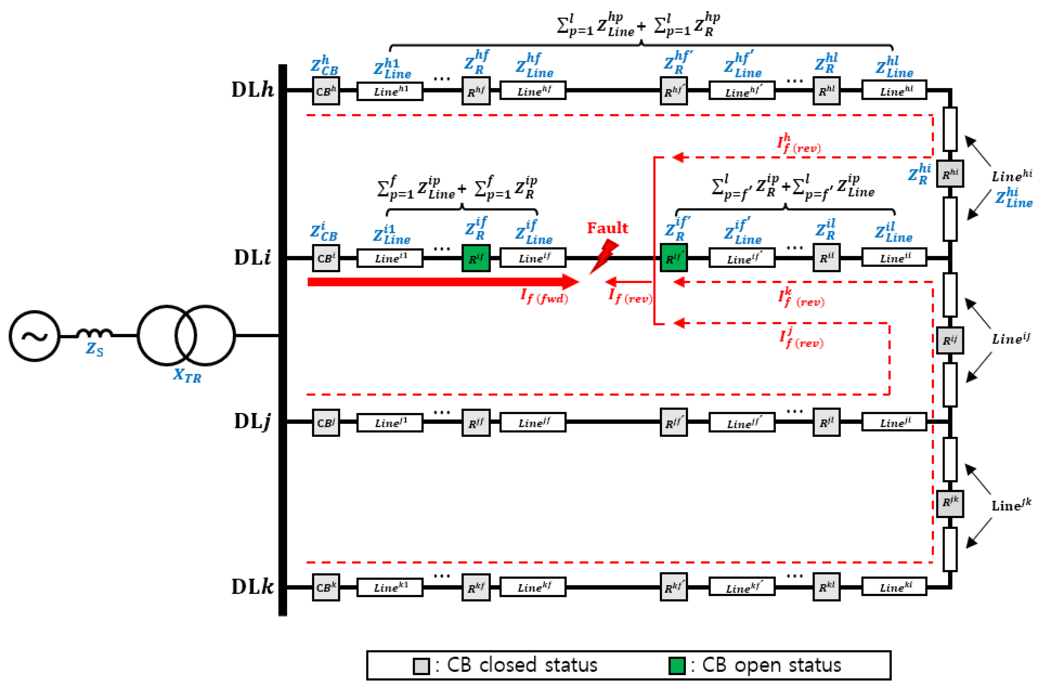
Figure 4 shows the fault current characteristics of NDS, and the nomenclature is shown in Table 3. Equation (6) shows the inverse relationship between the magnitude of the forward fault current and the facility impedance when a fault occurs in . On the other hand, Equation (7) represents the inverse relationship between the fault current and facility impedance in the reverse direction from to the fault point of . By utilizing Equation (7), the inverse relationship between the fault current and impedance in the reverse direction from and to the fault point of can be obtained. Equation (8) means that the sum of the reverse fault currents from , , and becomes the magnitude of the reverse fault current from . As a result, the magnitude of the reverse fault current on the fault line is inversely proportional to the sum of the facility impedances from other lines in the reverse direction based on the fault point. Therefore, the reverse fault current has relatively small characteristics compared to the forward fault current in the fault line.

Figure 4.
Bidirectional fault current characteristics of NDS.
Table 3.
The nomenclature used in Figure 4.
2.3. High-Impedance Fault
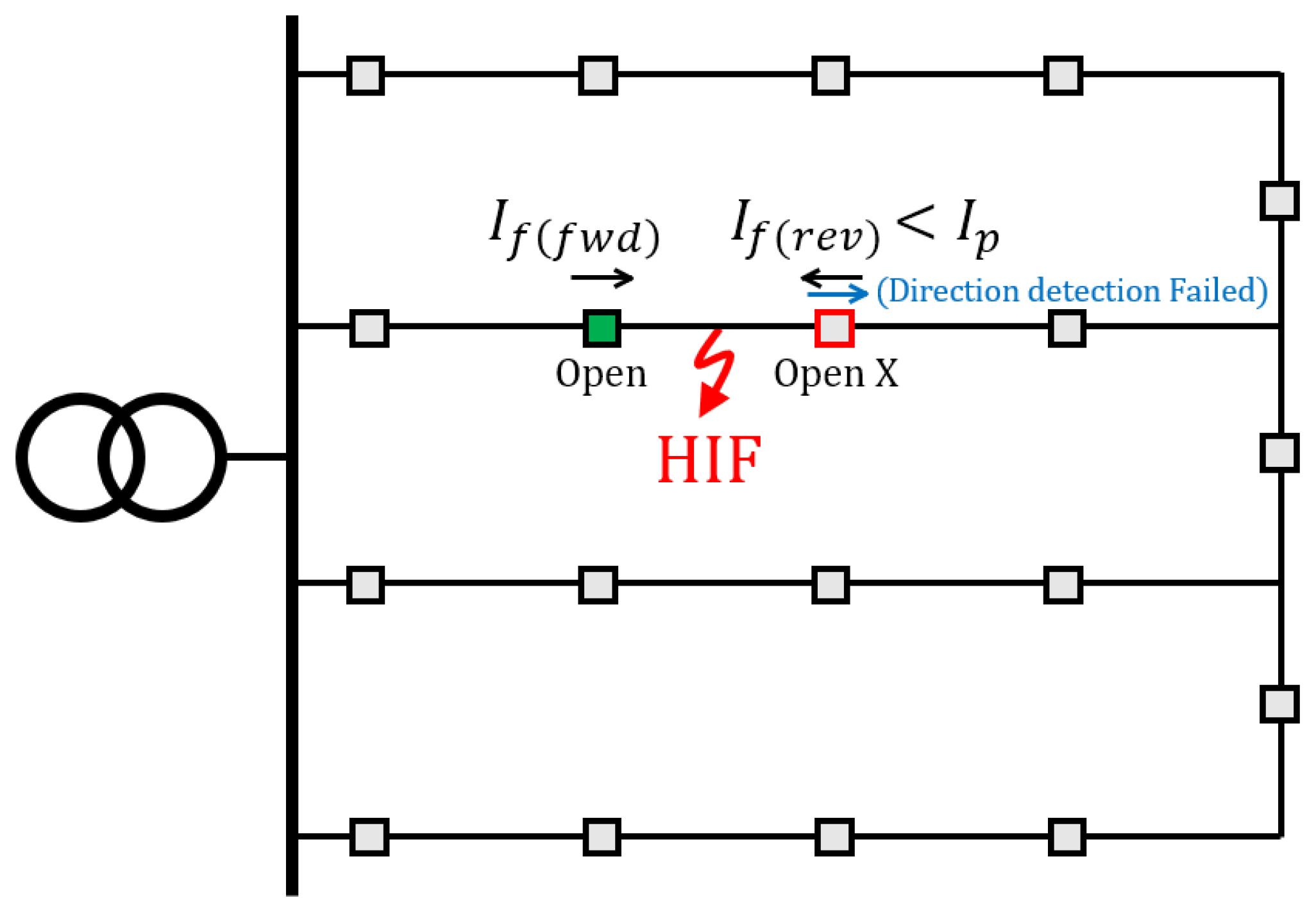
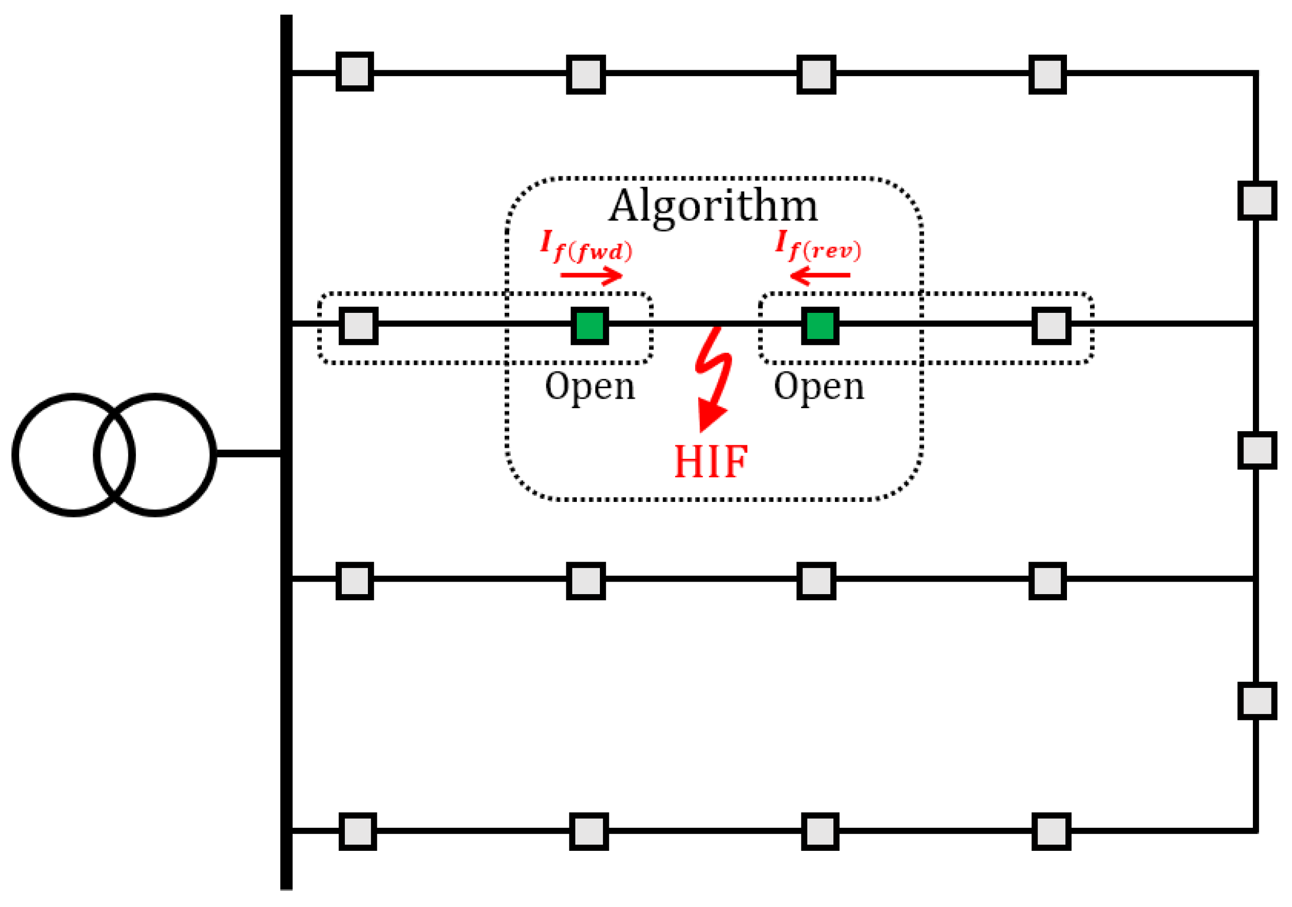
As mentioned earlier, when an HIF occurs, the fault current flowing through the system significantly decreases. This fault characteristic is due to the inverse proportion between fault current and fault impedance in Equation (9), where is the fault voltage and is the fault impedance. If becomes smaller than due to an HIF, operational issues with the protective device can occur. However, detecting an HIF in the system is challenging, and it can pose risks during long-term operations. Thus, HIF must be quickly detected and handled [26]. For stable system operation, various methods to detect HIFs and operate the distribution system safely have been proposed [27,28,29]. Figure 5 illustrates an HIF occurring in an NDS. In an NDS, the reverse fault current () is relatively small compared to the forward fault current (). When an HIF occurs in the NDS, the magnitude of the is further reduced. When the magnitude of the becomes smaller than , the reverse DOCR does not operate immediately, which may cause issues for the grid facilities. In addition, even if is larger than and the reverse DOCR operates, the reverse DOCR may malfunction due to a failure in direction detection resulting from an HIF.

Figure 5.
Conventional protection coordination under HIF in the NDS.
2.4. Distributed Generators Connection
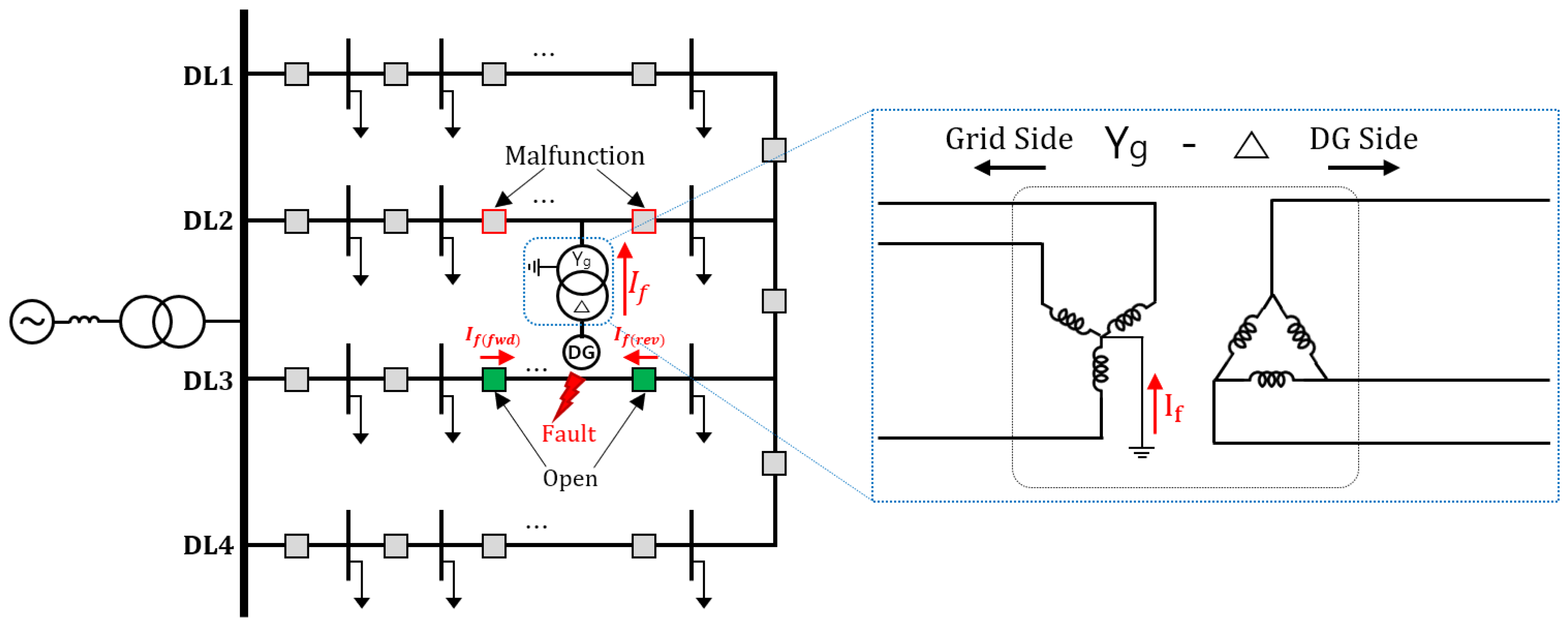
The left side of Figure 6 shows the DG connected to the NDS, and the right side shows the structure of the DG-linked transformer. Generally, when connecting DG to the distribution system, a Yg-D transformer is used for the connection. Although the impact of a short circuit fault in a DG-connected system is small, a ground fault can have a fatal impact on the system. This is because the ground fault current can propagate through the neutral line of the Yg transformer connected to the system. For example, as shown in Figure 6, when a fault occurs in DL3, the fault current generally flows in both the forward and reverse directions of DL3. Then, the protective device adjacent to the fault point opens to eliminate the fault. However, when a ground fault occurs, the fault current spreads to DL2 (other lines) through the neutral line of the connected DG. This can cause the malfunction of the protective device of DL2, which reduces the reliability of the grid supply. In addition, when multiple DGs are connected to the NDS, faults may propagate from various points where the DGs are connected, and direction detection of the protection device may also be negatively affected. Therefore, when connecting a DG to an NDS, it is necessary to analyze various failure scenarios in advance.

Figure 6.
DG connected to the NDS (left) and structure of the DG-linked transformer (right).
2.5. Proposed Protection Method
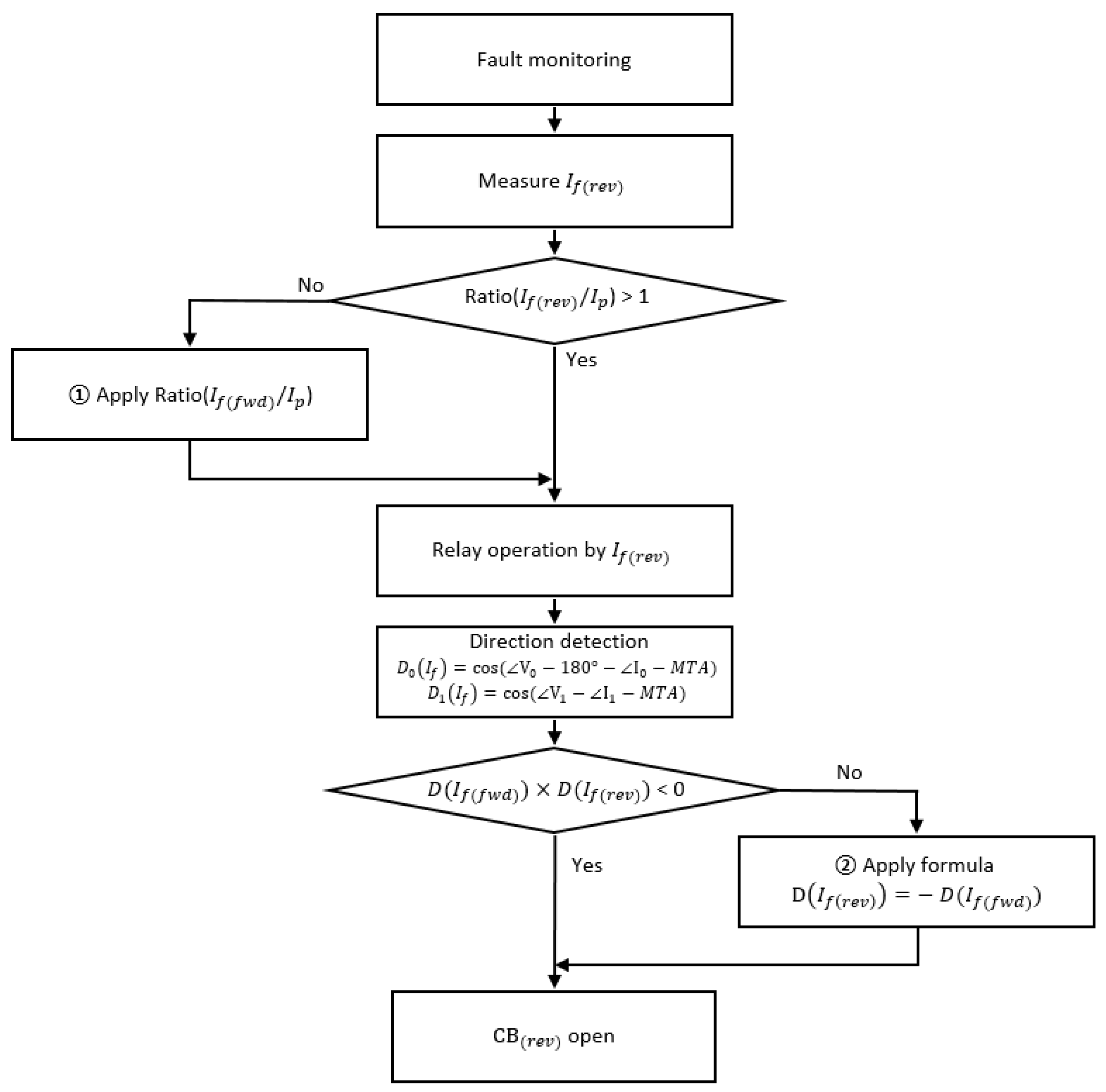
This paper proposes the communication-based protection algorithm described in Figure 7 for protection coordination in an NDS under an HIF. Due to the characteristics of the NDS, the reverse fault current is relatively small compared to the forward fault current, and this problem becomes more severe when an HIF occurs. The first step in the flowchart represents the detection of a fault occurrence. Since the of NDS is relatively large, the forward protective device can successfully identify an HIF. Therefore, the focus of the proposed protection method is to successfully detect the , when an HIF occurs but also to complement the issue of immediate operation failure or direction detection failure of the reverse protective device.

Figure 7.
Flowchart of the proposed protection coordination.
If condition > 1 is not met, the reverse DOCR does not operate immediately. In this condition, the forward DOCR operates first, and after the fault current is bypassed to the reverse DOCR, and when the condition > 1 is satisfied, then reverse DOCR operates. In other words, an operation time difference occurs between forward DOCR and reverse DOCR due to the HIF. Therefore, ratio is used by utilizing communication to ensure that the reverse DOCR can operate simultaneously with the forward relay. Then, direction detection is applied. Depending on the type of fault, Formula (2) is applied when a ground fault occurs and Formula (3) is applied when a short circuit fault occurs. In addition, as the fault current flowing in the two circuit breakers based on the fault point should be in opposite directions, condition < 0 must be met for correct direction detection. If direction detection fails, the relay recognizes the fault current of both circuit breakers as flowing in the same direction, and > 0 is met, possibly leading to relay malfunction. Hence, when direction detection fails, is used to enable direction detection by using communication.
As a result, when an HIF occurs, the proposed protection algorithm operates both the forward and reverse DOCR simultaneously. In addition, this algorithm aims to compensate for any failure in the protective device’s direction detection. By simultaneously tripping both breakers from the fault point, the HIF can be eliminated quickly. In addition, this protection algorithm can contribute to solving the protection coordination failures caused by the reversal of the zero-sequence direction of the protective device due to the time difference in the operation of the two breakers during a ground fault.
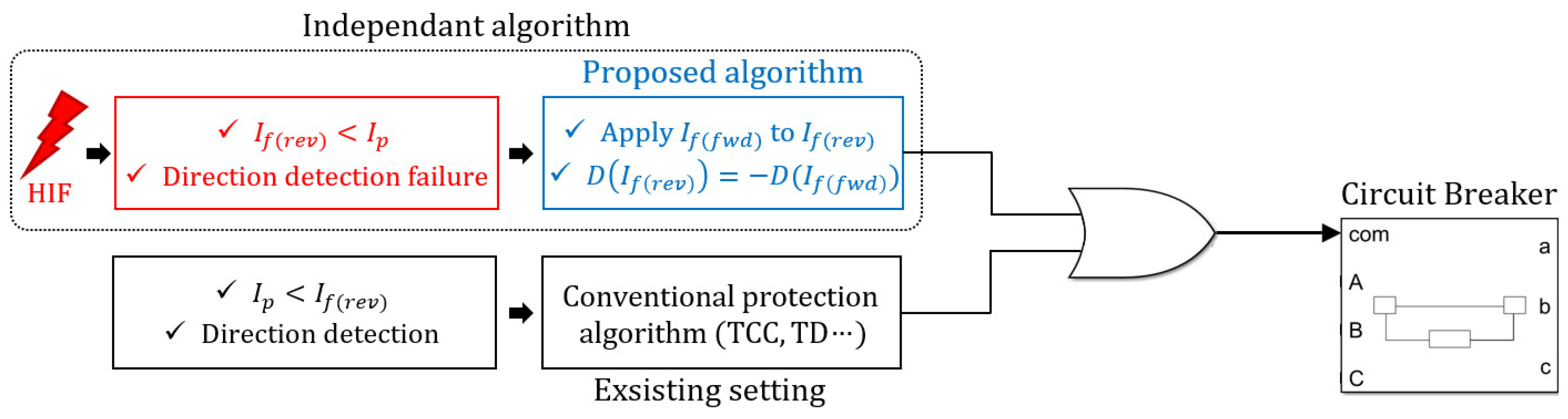
Figure 8 illustrates the protection logic and the process of breaker operation implemented in the protective device. In general, during failures, the conventional protection algorithm is applied, and the protective device operates with the existing setting values (TCC and TD). On the other hand, if the fault current becomes lower than the pickup current due to HIF or direction detection fails, the proposed protection algorithm is applied. The proposed protection algorithm is outputted through an OR gate along with the conventional one. In other words, the proposed protection algorithm is an independent protection algorithm that operates when an HIF occurs. Therefore, it does not interfere with existing protection settings.

Figure 8.
Protection relay operation logic and the process of the breaker.
Figure 9 illustrates protection coordination applying the proposed algorithm. The algorithm must be applied by grouping the logic of two circuit breakers into one set, and this algorithm should overlap for each pair of circuit breakers. Hence, when an HIF occurs within the protection area, immediate protective operation can be taken, even if ≤ , and protection coordination is possible even if direction detection fails.

Figure 9.
Operation of proposed protection coordination under an HIF in the NDS.
3. Case Study and Discussion
3.1. Test System
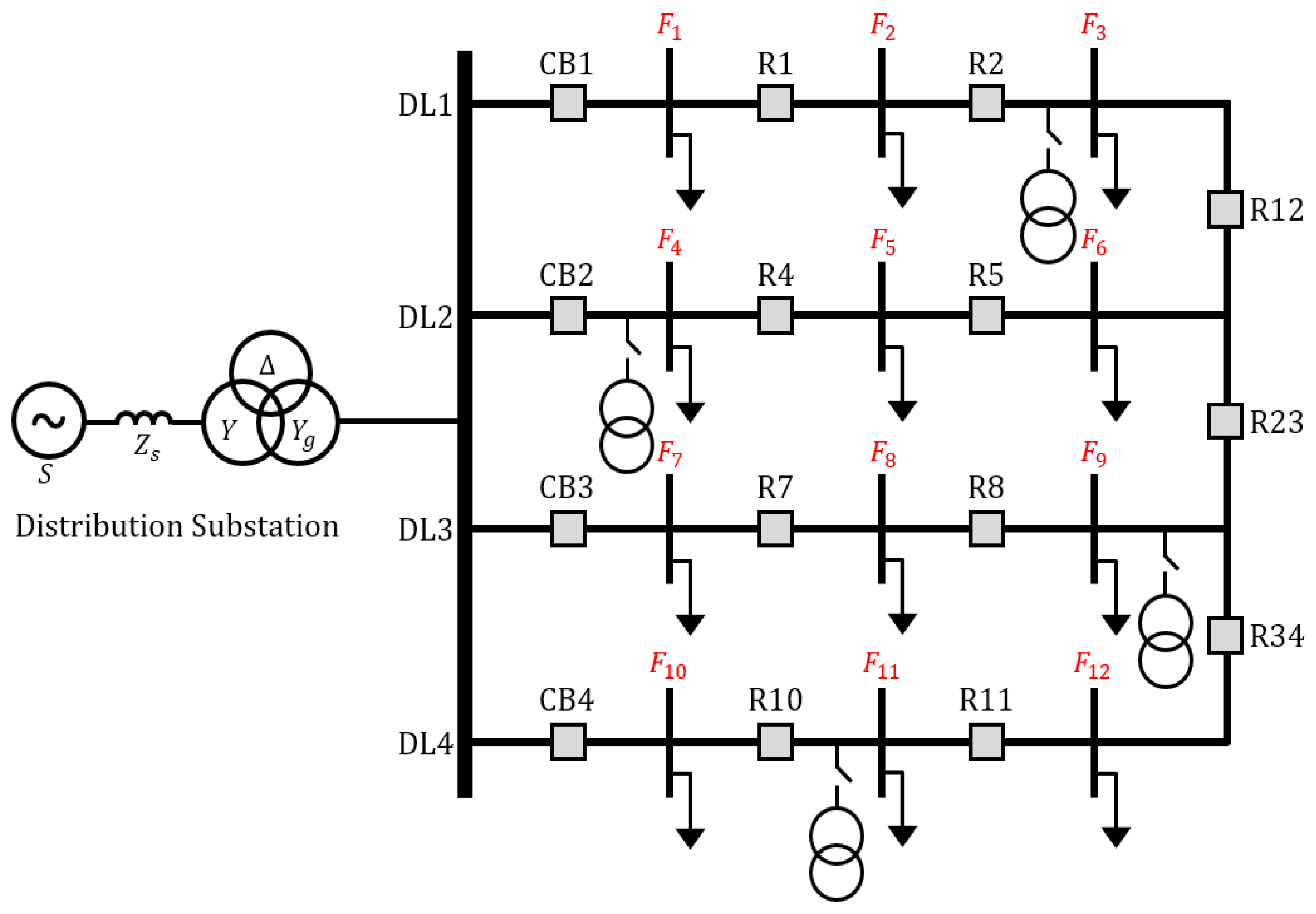
Figure 10 shows the NDS for the case study with the parameters listed in Table 4. The test system consists of a voltage source, a three-winding transformer (154/6.6/22.9 kV), a line (CNCV 325), and loads. The secondary delta connection of the transformer (Yg-Δ-Y) can mitigate the third harmonic, and a neutral grounding resistor of j0.6 Ω is linked to the tertiary transformer. Additionally, the NDS is established by interconnecting the ends of each 9 km distribution line (DL). In Figure 10, to represent the points where faults occur in the fault scenario. Table 5 shows the section length of the network and the locations where the load and DGs are connected for each case.

Figure 10.
NDS considered in case study.
Table 4.
Parameters of the NDS under study.
Table 5.
Section length and loads of each DL.
This test system reflects the characteristics of a typical Korean distribution system and adheres to the IEC 60255-3 very inverse curve for setting the protective devices. In Table 1, the A, B, C, and D are set to 13.5, 1, 1, and 0 for the case study. For the fault scenario, an HIF with a fault impedance of 10 ohms was applied to the entrance (, , and ), midpoint (, , and ), and terminal (, , and ) of each DL. The fault types were simulated as a single-line-to-ground (SLG) fault and a three-phase short circuit. Since SLG faults occur frequently in the system, it was conducted as a fault case. In addition, a three-phase short circuit fault has a low probability of occurrence in the power system, but when it occurs in the system, it adversely affects the grid facilities due to a large fault current, so it was applied as a fault case.
3.2. Case Study 1: Load Balance Conditions without DGs
First, to understand the operation characteristics of DOCR and fault current when HIF occurs in an NDS, Case 1 was simulated. In this simulation, a constant impedance load of 9 MW (3 loads × 3 MW) is connected to each DL, without any connections to DGs. To verify whether the protective device can operate normally, it was tested whether the fault current flows more than from the fault point to both circuit breakers. Additionally, to verify that direction detection is possible, it was tested whether the result was positive (+) and the result was negative (-) after the fault.
3.2.1. Single-Line-to-Ground Fault
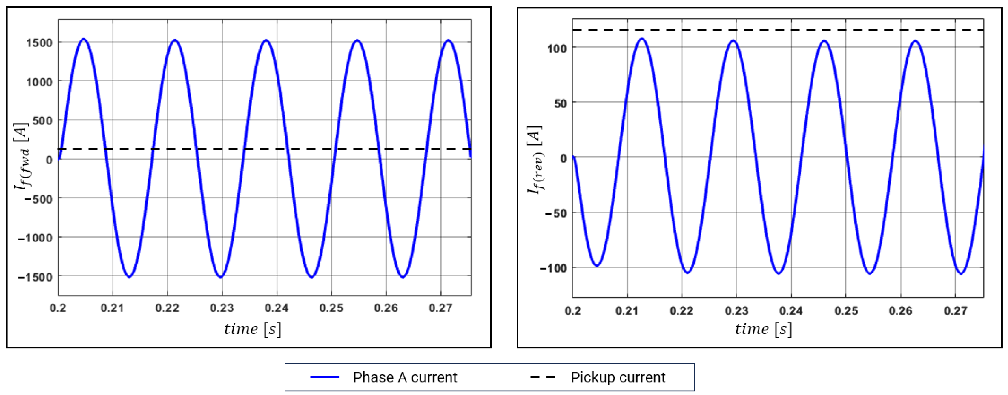
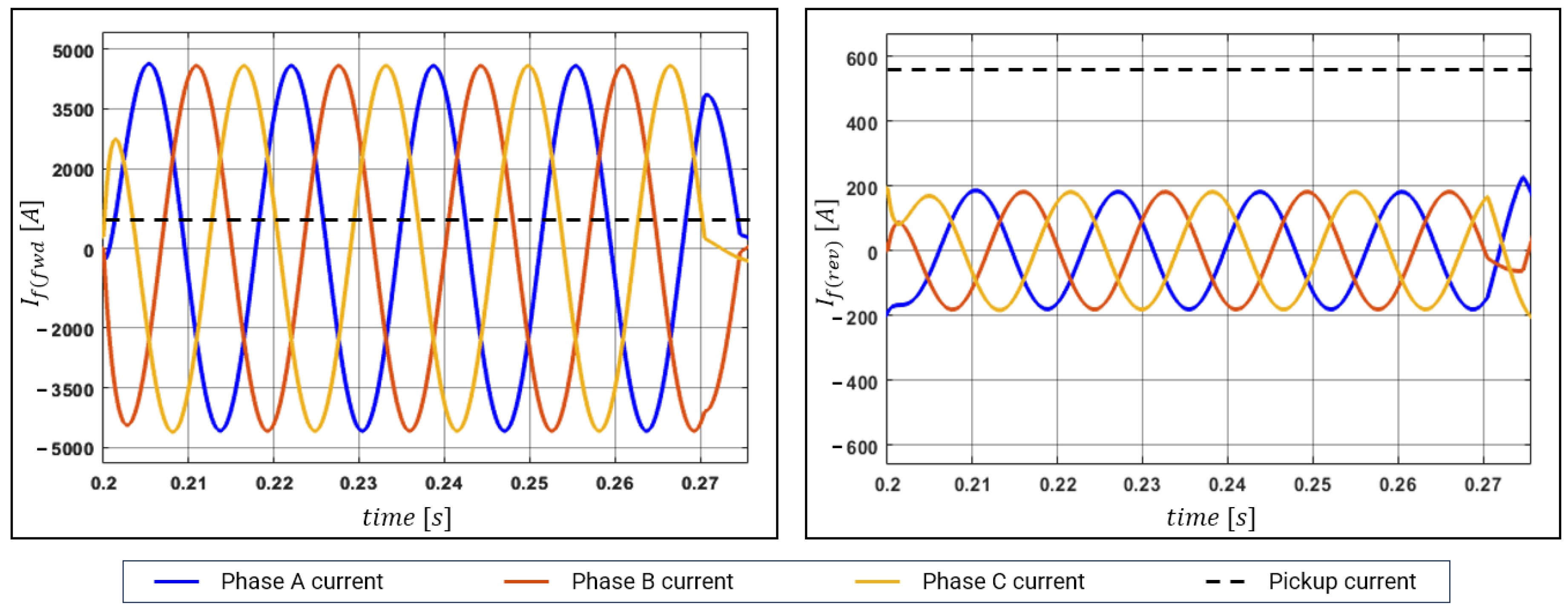
For the first scenario, a SLG fault was simulated at location of the test line. The fault resistance was set to 10 Ω (HIF) and applied at 0.2 s. In Korean distribution systems, the overcurrent ground relay is set to 70–80 A (RMS value). In this case study, 80 A was set for operation at approximately 113.14 A (peak value). The left graph of Figure 11 shows a waveform higher than 113.14 A (dotted line), indicating that the forward relay operates immediately. The right graph shows that the peak value does not reach 113.14 A, indicating that the relay does not operate immediately given the insufficient pickup current.

Figure 11.
Fault currents under SLG fault (HIF) ((left), forward; (right), reverse).
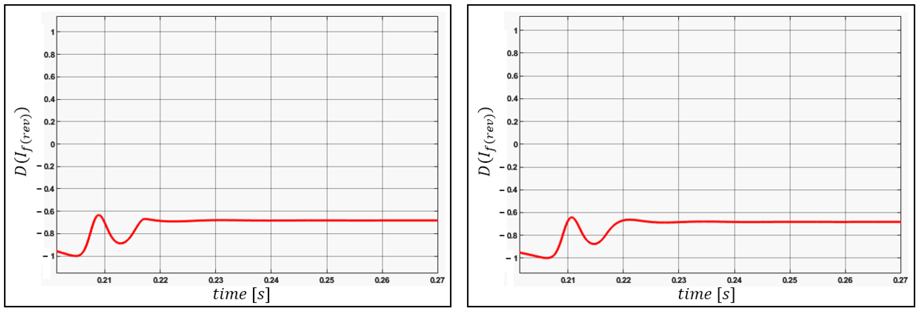
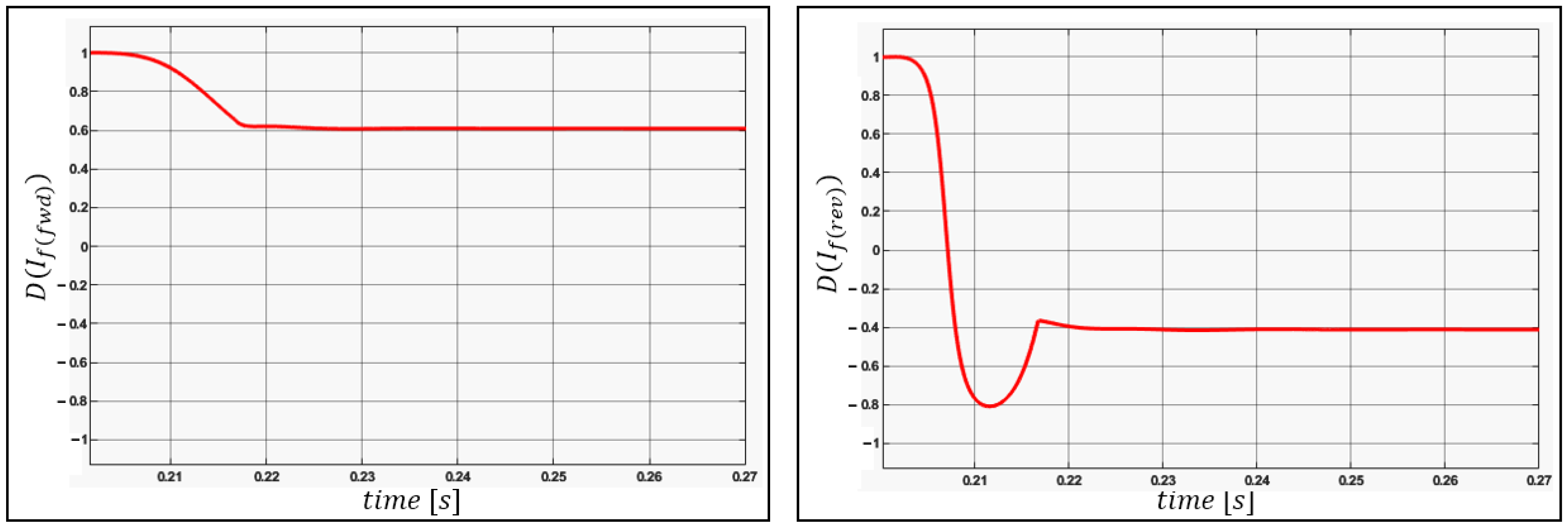
A ground fault was simulated in this scenario. For direction detection, the zero-sequence equation is applied under the HIF, and the detection result is shown in the left graph of Figure 12. When the reverse DOCR direction detection is successful, is negative, indicating successful direction detection under the SLG fault (HIF). The right graph of Figure 12 shows the result of a fault simulation after changing the fault resistance to 1 Ω for comparison with the HIF. Under the SLG fault, is less than and the relay does not operate. However, as direction detection is successful regardless of the size of the fault resistance, only stage ① in Figure 7 needs to be applied.

Figure 12.
Direction detection of SLG fault ((left), HIF; (right), 1 Ω).
3.2.2. Three-Phase Short Circuit
The second scenario simulated a three-phase short circuit in the NDS. In a three-phase short circuit, the magnitude of the fault current is larger than that of SLG. The size of the fault resistance was set to 10 Ω, as in the SLG scenario, to simulate the occurrence of an HIF. In Korean distribution systems, of the overcurrent relay is approximately 400 A (RMS value); thus, approximately 565.7 A (peak value) was set. The left graph of Figure 13 shows the waveform larger than 565.7 A, indicating that the forward relay operates immediately. On the other hand, the right graph of Figure 13 shows that does not reach 565.7 A, similar to the SLG scenario, indicating that the relay does not operate immediately because .

Figure 13.
Fault currents under three-phase short circuit (HIF) ((left), forward; (right), reverse).
As a three-phase short circuit is simulated, for direction detection, the positive-sequence equation is applied to the HIF, and the result is shown in the left graph of Figure 14. In this HIF scenario, is positive, indicating failure of direction detection. Thus, this scenario satisfies neither nor 0; thus, stages ① and ② in Figure 7 must be applied. The right graph of Figure 14 shows the result of direction detection after setting the fault resistance to 1 Ω for comparison with the HIF. The result for 1 Ω is negative, indicating successful direction detection. Hence, an HIF can cause the failure of DOCR direction detection. However, as shown in the right graph of Figure 14, when a system fault occurs, remains positive from 0.2 s to 0.206 s, taking approximately 0.02 s to reach stable direction detection.

Figure 14.
Direction detection of three-phase short circuit ((left), HIF; (right), 1 Ω).
3.2.3. Protection Coordination Analysis in NDS
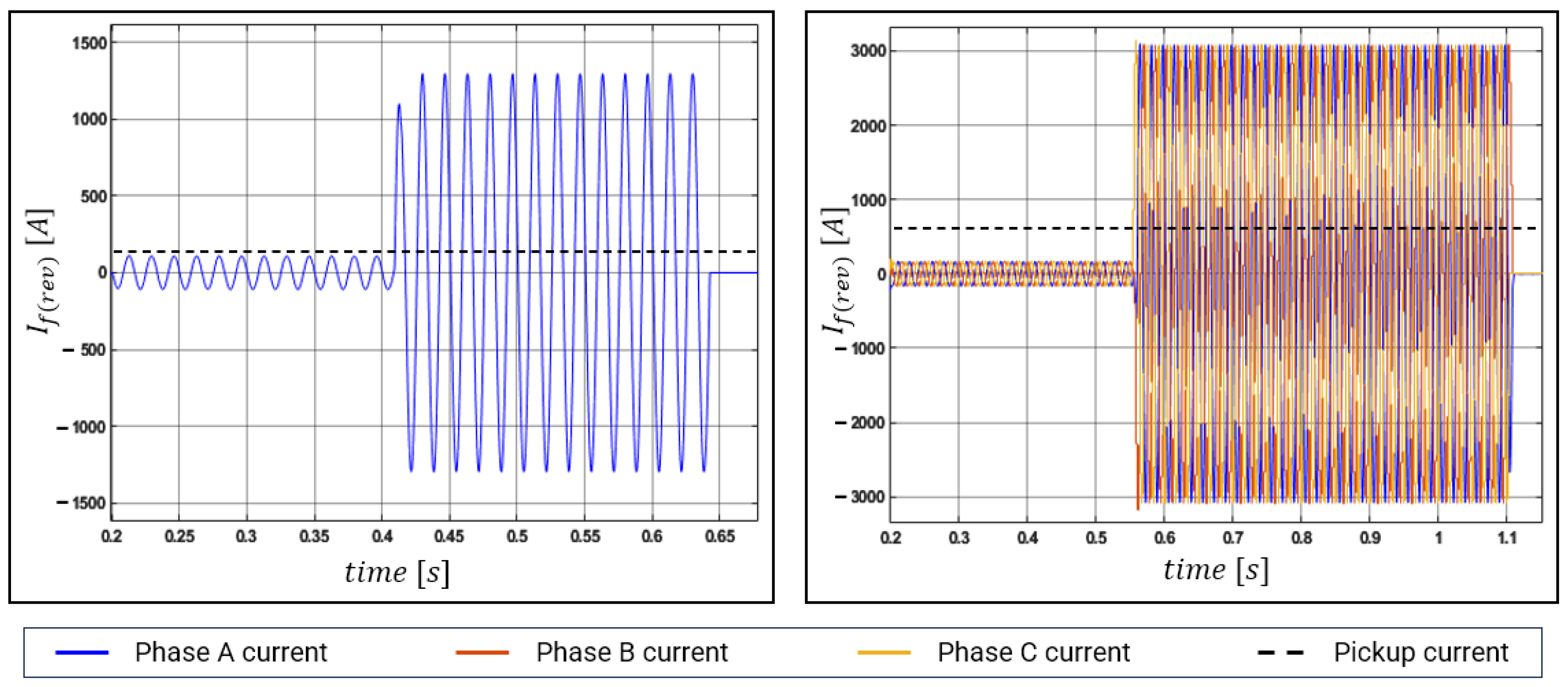
Figure 15 shows the reverse breaker operation under an SLG fault and three-phase short circuit, each with a fault resistance of 10 Ω (HIF), applied to point of the test NDS using the conventional method. When a fault is applied at 0.2 s, the forward breaker, owing to the forward TCC logic (), disconnects within 0.2 s under the SLG fault and within 0.33 s under the three-phase short circuit. This simulation result indicates that when the forward breaker eliminates the fault, the fault current bypasses in the reverse direction because is smaller than owing to the HIF. Then, the fault is eliminated by the reverse TCC logic (). Hence, the reverse breaker under the HIF does not meet , and the protective device does not operate immediately but instead takes a long time to trigger its operation. The total breaker operation time () is equivalent to the sum of the forward breaker operation time () and the reverse breaker operation time (), as defined in Equation (10). The delay in breaker operation time can cause the fault current, bypassing in the reverse direction to negatively impact the system equipment. Therefore, fast operation (i.e., short ) is required for system protection.

Figure 15.
Analysis of HIF current in NDS ((left), SLG fault; (right), three-phase short circuit).
3.2.4. Simulations and Results Using Proposed Method
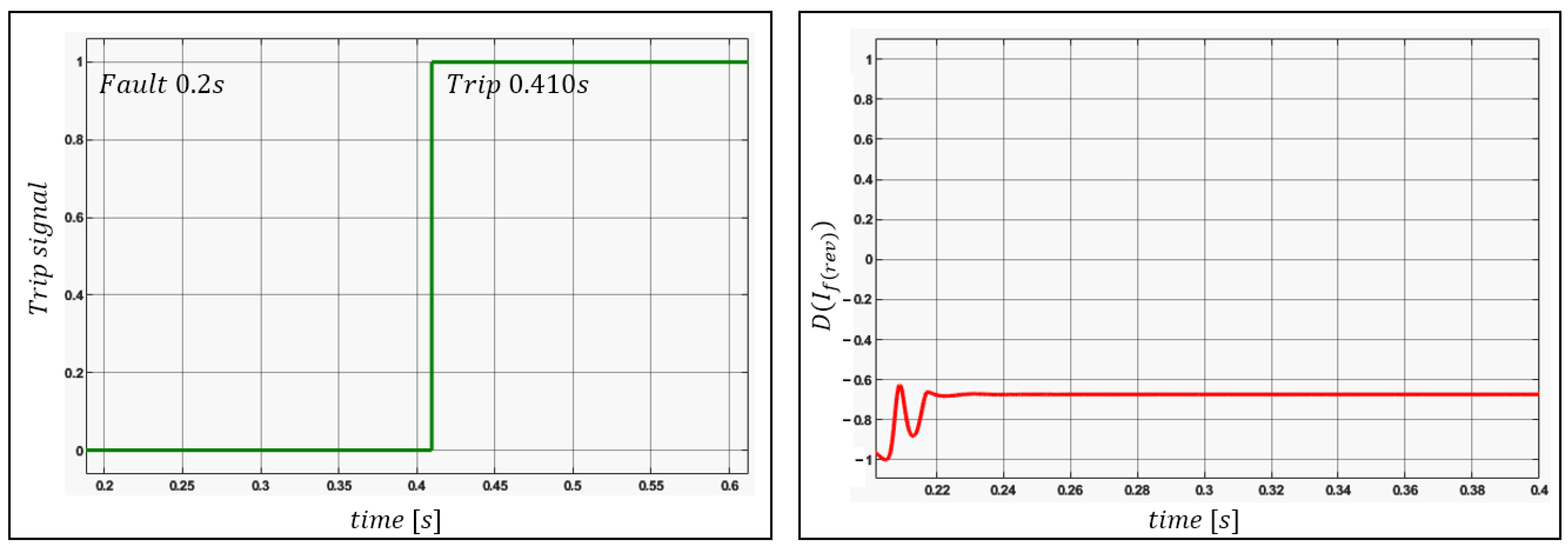
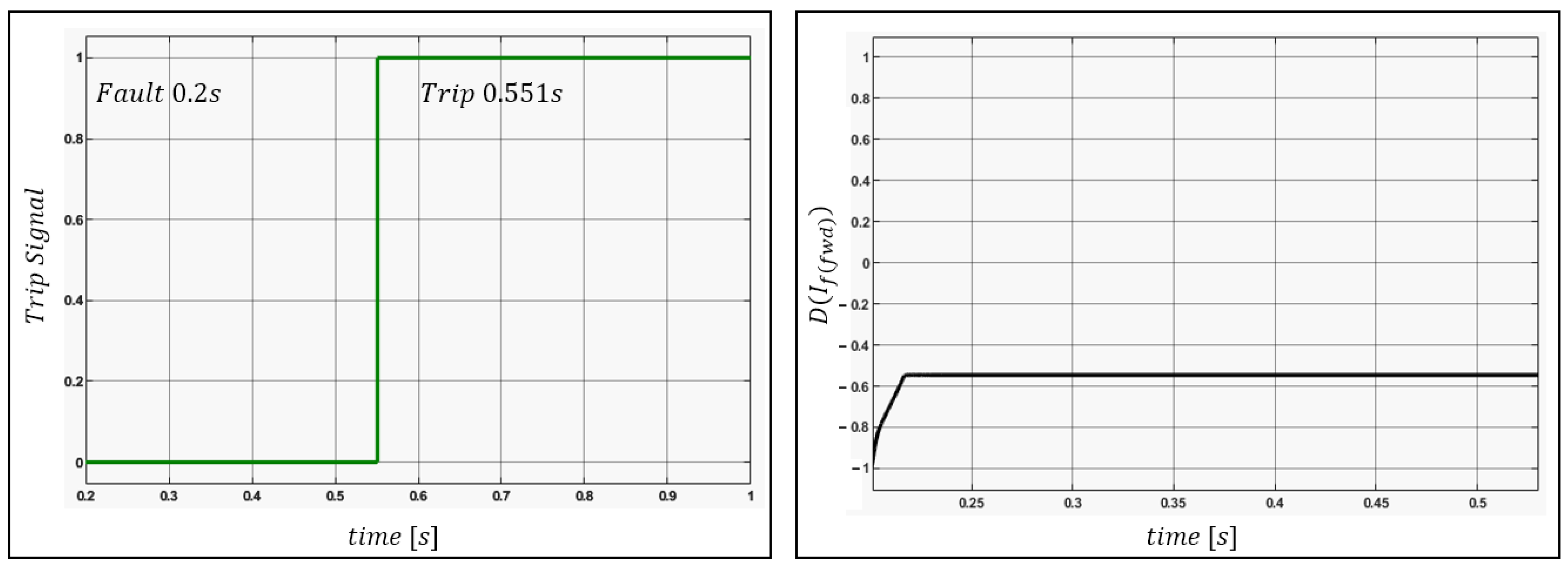
The proposed method drastically reduces by causing the reverse DOCR to operate simultaneously with the forward breaker under an HIF. Figure 16 shows using the proposed algorithm, which is 0.410 s (instead of 0.642 s obtained using the conventional method), being equal to under the SLG fault. As direction detection under the SLG fault is correct (Figure 12), the results of applying without modification are shown. Figure 17 shows the corresponding results under the three-phase short circuit. Using the proposed method, and are 0.551 s (instead of the 1.102 s obtained using the conventional method). However, as direction detection fails under the three-phase short circuit (Figure 14), was applied.

Figure 16.
Results of proposed method under SLG fault ((left), trip signal; (right), direction detection).

Figure 17.
Results of proposed method under three-phase short circuit ((left), trip signal; (right), direction detection).
3.3. Case Study 2: Different Load Size Conditions without DGs
An NDS is ideally organized by connecting the terminals when the line length is the same and the load pattern of each DL is different. This is because different load patterns on the same line allow load sharing and avoid load imbalance due to terminal voltage differences caused by line length differences. Therefore, in this case study, ideal networked test conditions were established by linking multiple lines with the same length and distinct load patterns to the terminal. In the test system, DL1, DL2, DL3, and DL4 were connected to loads of 7.8, 8.4, 9, and 9.6 MW (three loads × 2.6, 2.8, 3.0, and 3.2 MW), respectively, and the proposed protection algorithm was tested. The results of this scenario are listed in Table 6. Remarkably, in the conventional protection method, as the fault gets closer to the entrance of the feeder, increases with decreasing fault current owing to the higher reverse line impedance, thereby indicating that the proposed logic is more effective when the fault is closer to the entrance of the feeder. Hence, the proposed method can interrupt faults faster than the conventional method, suggesting its effectiveness for system protection.
Table 6.
Total breaker operation time (in seconds) under faults for conventional and proposed methods in case 2.
3.4. Case Study 3: Different Load Size Conditions with DGs
To prove the effectiveness of the proposed protection algorithm, a load size change scenario was simulated. When analyzing load consumption patterns, load consumption generally decreases sharply during the late night. In other words, a case study was conducted to check whether the protection algorithm operates appropriately, assuming a late-night situation where the line utilization rate is low due to a reduction in load size. The size of the load in Case 3 was set to half the amount of active power and reactive power of the load compared to Case 2. The simulation results are shown in Table 7, and compared to Case 2, the overall circuit breaker operation time decreases, but the trend shows a similar pattern. As a result, the proposed algorithm demonstrated the effectiveness of protective operation, even in late-night situations.
Table 7.
Total breaker operation time (in seconds) under faults for conventional and proposed methods in case 3.
3.5. Case Study 4: Different Load Size Conditions with DGs
In this case study, the DGs are connected by closing the switchgear in Figure 10 under the same load conditions as in Case 2 to analyze the impact on DOCR operation. The connection points of the DGs were arbitrarily set at the entrance, midpoint, and terminal of the DL. The results of this scenario are listed in Table 8. Compared to the results of Case 2, DGs did not have a significant impact on DOCR operation in the three-phase short circuit scenario, but DGs significantly affected DOCR operation in the SLG fault scenario. As mentioned earlier, this result is because when SLG occurs, the fault current flows into other DGs in the system through the neutral line of the Yg-D wound transformers. As shown in Table 8, in the SLG scenario of this case study, the tripping time was reduced for both the conventional protection method and the proposed protection method, and the direction of the fault current was also successfully detected. However, it is difficult to predict the flow of SLG fault current depending on the connection location of DGs, which not only affects the operating characteristics of the DOCR but also has the possibility of malfunctioning the DOCR. Therefore, before introducing the NDS into real-world power systems, additional studies on DG connection are required.
Table 8.
Total breaker operation time (in seconds) under faults for conventional and proposed methods in case 4.
4. Discussions and Conclusions
Renewable energy connection to the distribution system is rapidly increasing and supply reliability is becoming important. As a solution, research is being conducted to transpose the distribution system structure from the RDS to the NDS. However, due to the structural characteristics of the NDS, the protection coordination method becomes complicated as bidirectional fault current flows. Additionally, due to the characteristics of NDS, compared to the forward fault current, the reverse fault current is relatively small and becomes more severe when HIF occurs.
First, in this paper, the impact of HIF on protective devices was verified and analyzed through simulation. According to the simulation results, in the event of an HIF, if the reverse fault current becomes smaller than the pickup current, it could cause a delay in operation time. This delay occurs because the reverse protective device only operates after the forward fault has been removed and the fault current bypassed. In addition, protective device malfunction issues may occur due to direction detection failure caused by the HIF.
Therefore, this paper proposes a communication-based protection algorithm as a solution when an HIF occurs in NDS. When an HIF occurs in NDS, the operation delay issues of the reverse protective device can be solved through the proposed protection algorithm, and the fault can be quickly eliminated. In addition, the proposed algorithm can address the issue of protective device malfunction caused by direction detection failure.
The proposed method is an economical solution as it can be incorporated into existing protective devices without new devices such as BTB converters and superconducting fault-current limiters. Additionally, since it operates as an independent algorithm, it does not affect the settings of existing protective devices. Therefore, it has the advantage of not increasing the complexity of protection coordination. Consequently, the proposed method provides a potentially economical and efficient solution for protection.
The impact of the DGs connected to the NDS was also analyzed. The case study confirmed that the operation time of protective devices is affected when a ground fault occurs. In particular, the ground fault current can spread throughout the system via the neutral line of the Yg-D transformer. This makes predicting difficult and could cause malfunction issues in protective devices. Therefore, in-depth research on connections to DGs is necessary before introducing NDS into real-world power systems.
The focus of this study is to provide protection coordination through communication-based algorithms when an HIF occurs in the NDS. Currently, this research is in its initial stage, and optimization of the protective device’s parameter settings was not considered. However, future research will aim to optimize these settings and conduct more comprehensive protection coordination studies. These will include operations of primary protection and backup protection in the NDS-connected DGs. It is expected that precise protection coordination will be possible in more diverse fault scenarios through future research.
Author Contributions
Conceptualization, J.N., W.C. and W.K.; Data curation, J.N. and S.C.; Formal analysis, J.N. and S.G.; Funding acquisition, S.C.; Investigation, S.C.; Methodology, J.N., S.G. and M.Y.; Project administration, W.C., W.K. and S.C.; Resources, W.K.; Software, J.N. and S.G.; Supervision, S.C.; Validation, J.N., and M.Y.; Visualization, J.N. and S.C.; Writing—original draft, J.N.; Writing—review and editing, J.N. and S.C. All authors have read and agreed to the published version of the manuscript.
Funding
This research was supported in part by the Human Resources Program in Energy Technology of the Korea Institute of Energy Technology Evaluation and Planning (KETEP) and the Ministry of Trade, Industry & Energy (MOTIE) of the Republic of Korea (No. 20204010600220) and in part by the Korea Institute of Energy Technology Evaluation and Planning (KETEP) grant funded by the Korea government (MOTIE) (No. RS-2023-00234707).
Institutional Review Board Statement
Not applicable.
Informed Consent Statement
Not applicable.
Data Availability Statement
Not applicable.
Conflicts of Interest
The authors declare no conflict of interest.
References
- Strachan, N.; Hadi, D. Distributed generation and distribution utilities. Energy Policy 2002, 30, 649–661. [Google Scholar] [CrossRef]
- Azibek, B.; Abukhan, A.; Nunna, H.K.; Mukatov, B.; Kamalasadan, S.; Doolla, S. Hosting capacity enhancement in low voltage distribution networks: Challenges and solutions. In Proceedings of the 2020 IEEE International Conference on Power Electronics, Smart Grid and Renewable Energy (PESGRE2020), Cochin, India, 2–4 January 2020. [Google Scholar] [CrossRef]
- Dubey, A.; Santoso, S.; Maitra, A. Understanding photovoltaic hosting capacity of distribution circuits. In Proceedings of the 2015 IEEE Power & Energy Society General Meeting, Denver, CO, USA, 26–30 July 2015. [Google Scholar] [CrossRef]
- Jacob, R.A.; Zhang, J. Distribution network reconfiguration to increase photovoltaic hosting capacity. In Proceedings of the 2020 IEEE Power & Energy Society General Meeting (PESGM), Montreal, QC, Canada, 2–6 August 2020. [Google Scholar] [CrossRef]
- Ismael, S.M.; Aleem, S.H.A.; Abdelaziz, A.Y.; Zobaa, A.F. Practical considerations for optimal conductor reinforcement and hosting capacity enhancement in radial distribution systems. IEEE Access 2018, 6, 27268–27277. [Google Scholar] [CrossRef]
- Ali, Q.; Ahmad, H.W.; Kazmi, S.A.A. Looping of radial distribution network to mitigate the over voltage problems and to increase the integrated capacity of solar PV. In Proceedings of the 2019 International Conference on Electrical, Communication, and Computer Engineering (ICECCE), Swat, Pakistan, 24–25 July 2019. [Google Scholar] [CrossRef]
- Davoudi, M.; Cecchi, V.; Agüero, J.R. Investigating the ability of meshed distribution systems to increase penetration levels of distributed generation. In Proceedings of the IEEE SOUTHEASTCON 2014, Lexington, KY, USA, 13–16 March 2014. [Google Scholar] [CrossRef]
- Cruz, M.R.M.; Fitiwi, D.Z.; Santos, S.F.; Catalão, J.P.S. Meshed operation of distribution network systems: Enabling increased utilization of variable RES power. In Proceedings of the 2018 IEEE International Conference on Environment and Electrical Engineering and 2018 IEEE Industrial and Commercial Power Systems Europe (EEEIC/I&CPS Europe), Palermo, Italy, 12–15 June 2018. [Google Scholar] [CrossRef]
- Rahi, S.B.; Bisui, S.; Misra, S.C. Identifying critical challenges in the adoption of cloud-based services. Int. J. Commun. Syst. 2017, 30, e3261. [Google Scholar] [CrossRef]
- Wiboonrat, M. Risk anatomy of data center power distribution systems. In Proceedings of the 2008 IEEE International Conference on Sustainable Energy Technologies, Singapore, 24–27 November 2008. [Google Scholar]
- Celli, G.; Pilo, F.; Pisano, G.; Allegranza, V.; Cicoria, R.; Iaria, A. Meshed vs. radial MV distribution network in presence of large amount of DG. In Proceedings of the IEEE PES Power Systems Conference and Exposition, New York, NY, USA, 10–13 October 2004. [Google Scholar] [CrossRef]
- Kim, W.-H.; Kim, J.-Y.; Chae, W.-K.; Kim, G.; Lee, C.-K. LSTM-Based Fault Direction Estimation and Protection Coordination for Networked Distribution System. IEEE Access 2022, 10, 40348–40357. [Google Scholar] [CrossRef]
- Kim, W.H.; Chae, W.K.; Lee, J.W.; Lee, H.M.; Lee, C.K. Active TCC based protection coordination scheme for networked distribution system. Int. J. Electr. Power Energy Syst. 2023, 153, 109341. [Google Scholar] [CrossRef]
- Zeineldin, H.H.; Sharaf, H.M.; Ibrahim, D.K.; Abou El-Zahab, E.E.D. Optimal protection coordination for meshed distribution systems with DG using dual setting directional over-current relays. IEEE Trans. Smart Grid 2015, 6, 115–123. [Google Scholar] [CrossRef]
- Viawan, F.A.; Karlsson, D.; Sannino, A.; Daalder, J. Protection scheme for meshed distribution systems with high penetration of distributed generation. In Proceedings of the 2006 Power Systems Conference: Advanced Metering, Protection, Control, Communication, and Distributed Resources, Clemson, SC, USA, 14–17 March 2006; pp. 99–104. [Google Scholar] [CrossRef]
- Hatata, A.Y.; Ebeid, A.S.; El-Saadawi, M.M. Optimal restoration of directional overcurrent protection coordination for meshed distribution system integrated with DGs based on FCLs and adaptive relays. Electr. Power Syst. Res. 2022, 205, 107738. [Google Scholar] [CrossRef]
- Cao, W.; Wu, J.; Jenkins, N.; Wang, C.; Green, T. Operating principle of soft open points for electrical distribution network operation. Appl. Energy 2016, 164, 245–257. [Google Scholar] [CrossRef]
- Wang, C.; Song, G.; Li, P.; Ji, H.; Zhao, J.; Wu, J. Optimal siting and sizing of soft open points in active electrical distribution networks. Appl. Energy 2017, 189, 301–309. [Google Scholar] [CrossRef]
- Marano-Marcolini, A.; Romero-Ramos, E.; Gomez-Exposito, A.; Maza-Ortega, J.M.; Martinez-Ramos, J.L. Enhancing the integration of renewable sources in distribution systems using DC-links. In Proceedings of the 2009 IEEE PES/IAS Conference on Sustainable Alternative Energy (SAE), Valencia, Spain, 28–30 September 2009. [Google Scholar] [CrossRef]
- Cao, W.; Wu, J.; Jenkins, N.; Wang, C.; Green, T. Benefits analysis of soft open points for electrical distribution network operation. Appl. Energy 2016, 165, 36–47. [Google Scholar] [CrossRef]
- Qi, Q.; Wu, J. Increasing distributed generation penetration using network reconfiguration and soft open points. Energy Procedia 2017, 105, 2169–2174. [Google Scholar] [CrossRef]
- Sciano, D.; Raza, A.; Salcedo, R.; Diaz-Aguilo, M.; Uosef, R.E.; Czarkowski, D.; De Leon, F. Evaluation of DC links on dense-load urban distribution networks. IEEE Trans. Power Del. 2015, 31, 1317–1326. [Google Scholar] [CrossRef]
- Alvarez-Herault, M.C.; N’doye, N.; Gandioli, C.; Hadjsaid, N.; Tixador, P. Meshed distribution network vs reinforcement to increase the distributed generation connection. Sustain. Energy Grids Netw. 2015, 1, 20–27. [Google Scholar] [CrossRef]
- Gandioli, C.; Alvarez-Hérault, M.C.; Tixador, P.; Hadjsaid, N.; Medina, D.M.R. Innovative distribution networks planning integrating superconducting fault current limiters. IEEE Trans. Appl. Supercond. 2013, 23, 5603904. [Google Scholar] [CrossRef]
- Alkaran, D.S.; Vatani, M.R.; Sanjari, M.J.; Gharehpetian, G.B.; Naderi, M.S. Optimal overcurrent relay coordination in interconnected networks by using fuzzy-based GA method. IEEE Trans. Smart Grid 2016, 9, 3091–3101. [Google Scholar] [CrossRef]
- Ghaderi, A.; Ginn, H.L., III; Mohammadpour, H.A. High impedance fault detection: A review. Electr. Power Syst. Res. 2017, 143, 376–388. [Google Scholar] [CrossRef]
- Michalik, M.; Rebizant, W.; Lukowicz, M.; Lee, S.J.; Kang, S.H. High-impedance fault detection in distribution networks with use of wavelet-based algorithm. IEEE Trans. Power Del. 2006, 21, 1793–1802. [Google Scholar] [CrossRef]
- Lima, É.M.; de Almeida Coelho, R.; Brito, N.S.D.; de Souza, B.A. High impedance fault detection method for distribution networks under non-linear conditions. Int. J. Electr. Power Energy Syst. 2021, 131, 107041. [Google Scholar] [CrossRef]
- Wang, X.; Wei, X.; Gao, J.; Song, G.; Kheshti, M.; Guo, L. High-impedance fault detection method based on stochastic resonance for a distribution network with strong background noise. IEEE Trans. Power Del. 2022, 37, 1004–1016. [Google Scholar] [CrossRef]
Disclaimer/Publisher’s Note: The statements, opinions and data contained in all publications are solely those of the individual author(s) and contributor(s) and not of MDPI and/or the editor(s). MDPI and/or the editor(s) disclaim responsibility for any injury to people or property resulting from any ideas, methods, instructions or products referred to in the content. |
© 2023 by the authors. Licensee MDPI, Basel, Switzerland. This article is an open access article distributed under the terms and conditions of the Creative Commons Attribution (CC BY) license (https://creativecommons.org/licenses/by/4.0/).