Review

Development of Control Techniques for AC Microgrids: A Critical Assessment

by
Pabel Alberto Cárdenas
,
Maximiliano Martínez
,
Marcelo Gustavo Molina
and
Pedro Enrique Mercado
*
Instituto de Energía Eléctrica, Universidad Nacional de San Juan-CONICET, San Juan J5400, Argentina
*
Author to whom correspondence should be addressed.
Sustainability 2023, 15(21), 15195; https://doi.org/10.3390/su152115195
Submission received: 6 September 2023 / Revised: 12 October 2023 / Accepted: 17 October 2023 / Published: 24 October 2023
(This article belongs to the Special Issue Power Systems Engineering Applications for a Sustainable Future)

Abstract

:
This article aims to provide a comprehensive review of control strategies for AC microgrids (MG) and presents a confidently designed hierarchical control approach divided into different levels. These levels are specifically designed to perform functions based on the MG’s mode of operation, such as grid-connected or islanded mode. The primary control ensures frequency (f) and voltage (V) stability, whereas the secondary control adjusts their values to their references and the tertiary control efficiently manages the power of distributed generators (DGs) in a cost-effective manner. The article extensively discusses centralized, decentralized, and distributed strategies for each control level, highlighting their differences, advantages, disadvantages, and areas of application. Finally, the usefulness of different control strategies at different levels is demonstrated through practical examples.

1. Introduction

The future of traditional distribution networks is focused on small distributed generators (DGs), which, due to their features and requirements of zero greenhouse gas emissions, will predominantly be renewable [1,2,3]. Due to growing environmental concerns, the use of thermal-based DGs such as diesel generators or gas turbines is expected to decrease over time. Instead, there is a shift towards systems that rely entirely on renewable energy sources. Unlike traditional generators, DGs are installed near consumption sources, allowing for local energy production. Some advantages of distributed generation are a reduction in losses, self-consumption, and the feasible adaptation of renewable energy sources. However, including DGs without a proper coordinated scheme can cause waveform distortions, voltage fluctuations, protection failures due to bidirectional flows, and other issues related to power quality [4].
In case of severe power network failures or contingencies, these DGs are typically disconnected for security and do not provide backup to reduce the expected energy not supplied (EENS). The microgrid (MG) then emerges as a novel reliable and resilient subsystem against contingencies, integrating distributed generation and allowing it to operate properly even when isolated from the main electrical system. By including DGs in the control environment of the MG, two operating modes can be distinguished: The first is the grid-connected state of operation, where DGs take frequency (f) and voltage (V) references from the main grid, and the second is island mode, which allows them to continue operating while disconnected from the main grid while f and V references are established by at least one of the DGs [5].
The infrastructure of existing networks, the type of DGs to be integrated, and other specifications oriented toward end-users determine the most suitable architecture of the MG, which can be AC, DC, or hybrid [6,7]. Economic, energy quality, reliability, stability, and resilience concerns generate interest among researchers and network operators to study different MG architectures and control strategies [6,8]. In these, the operation between all the DGs is addressed through a hierarchical approach of levels or layers, which, depending on the communication links available, can use one strategy or another.
This study presents an overview of the hierarchical approach in AC MGs considering different control strategies, which can be visualized in Figure 1 and Figure 2 [9,10]. Depending on the control level analyzed (primary, secondary, or tertiary), the response times and functions performed are different, as follows: The primary control is the fastest of all, with short response times typically around milliseconds if performed by inverter-based generation and a bit slower if performed by synchronous machines. The primary control coordinates the internal control of the DGs to keep the MG stable, i.e., it stabilizes f and V but in values different from the nominal ones, using fast and efficient strategies. Centralized and decentralized strategies are implemented at this level, with droop control being used the most for stability and power sharing between all DGs [11]. Droop control provides effective load contribution without the need for communication links.
The secondary control takes place within the span of several seconds to a few minutes and is responsible for restoring f and V values by reducing deviations to zero. It acts after the primary control, comparing the measured values with their references and processing the errors to send them to the DGs to restore their parameters. Given the characteristics of its functions, it requires communication links and can use distributed or centralized control strategies. The tertiary control is the slowest and operates within the span of several minutes to hours. It manages the optimal flow, as well as the dispatch of DGs through technical–economic criteria, and like the previous level, uses distributed or centralized strategies for its tasks [4,6,12].
To delve deeper into the study of hierarchical control in MGs, different techniques and methods have been investigated at all levels, in which a specific purpose or function is assigned. In addition, application areas are presented, ultimately evaluating the advantages and disadvantages. Structurally, the study continues to address the topic in Section 2, which discusses AC MG principal components, and in Section 3, which discusses the hierarchical control in MGs, including all levels or layers. This is followed by Section 4, Section 5 and Section 6, which present control strategies, and concludes with Section 7, Section 8 and Section 9, which present the examples, comments and discussion, and conclusion and references, respectively.

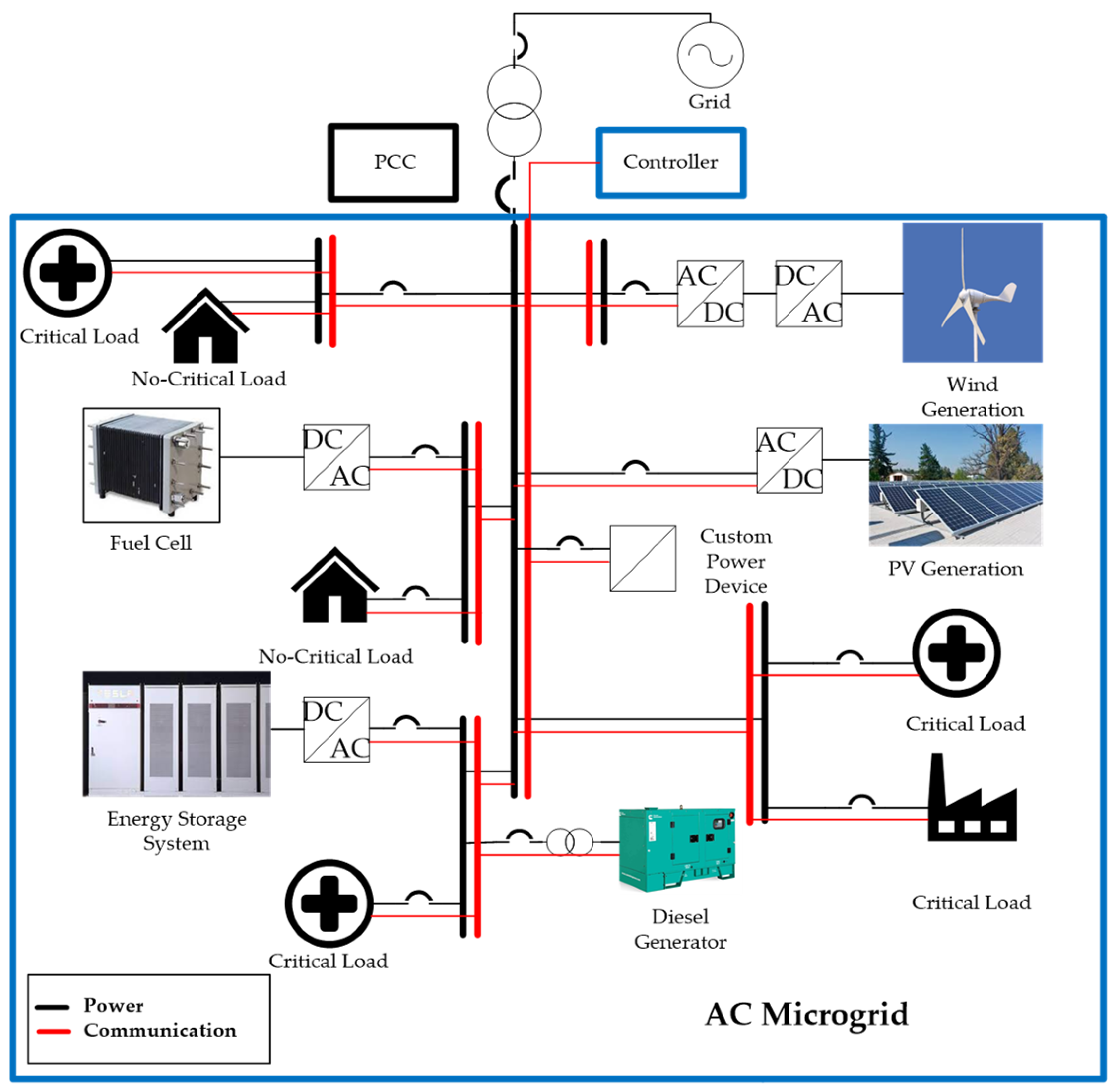
2. AC Microgrids and Principal Components

An MG is a portion of an electrical system that comprises linear or non-linear loads and DGs (distributed generators) such as solar generation, wind generation, fuel cells, fossil fuel-based generation, energy storage devices, and, more recently, custom power devices (CPDs). These devices collaborate to form a subsystem that can function either independently or in conjunction with the main electrical grid [13,14,15,16,17,18,19]. One of the two operational modes of an MG is the mode that is disconnected from the main grid, also referred to as island mode, isolated mode, standalone mode, or autonomous mode [6,20]. The other mode is connected mode, in which the MG is linked to the main power grid at the point of common coupling (PCC), as illustrated in Figure 3 [21,22,23]. Depending on the availability of primary resources for DGs, the MG may import or export power to/from the main grid in this mode.
Among various architectures, the AC MG is considered the dominant type, in which most DGs connect to the distribution system through a power electronics interface to supply part or all of the user’s demand [6,24]. Additionally, the DGs can also be connected through transformers. This DGs are typically synchronous or induction machine-type generation. Figure 3 shows an example of an AC MG whose subsystem environment can be observed. Regardless of the MG mode of operation, its control systems are essential for performing basic power injection purposes. Multi-level control strategies are typically used to achieve objectives such as optimal dispatch, operating cost minimization, and improved power quality [4].
To enhance the functionality of MGs with resilient, secure, and reliable approaches, researchers have explored the incorporation of energy storage systems (ESSs) and, more recently, custom power devices (CPDs).

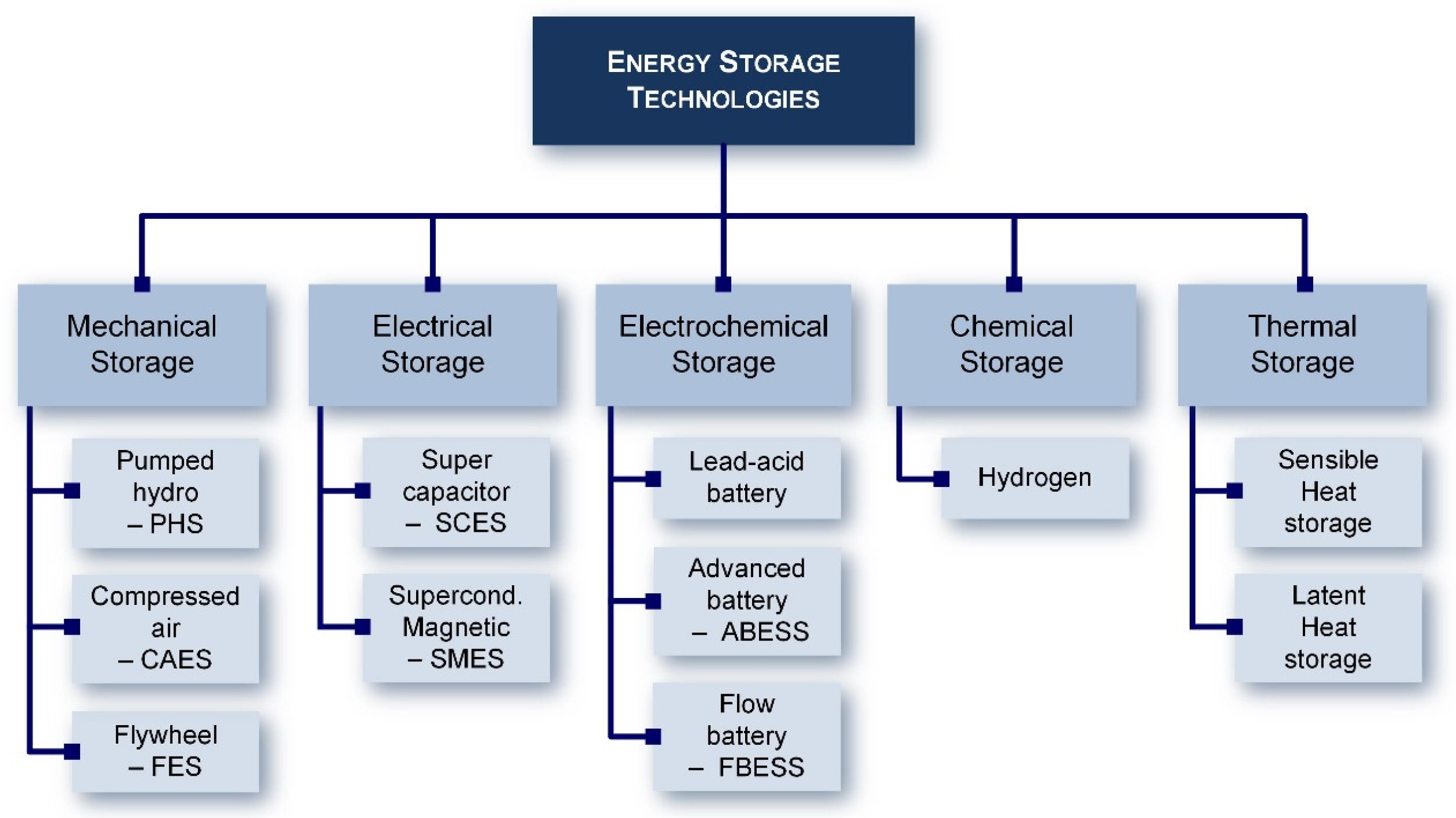
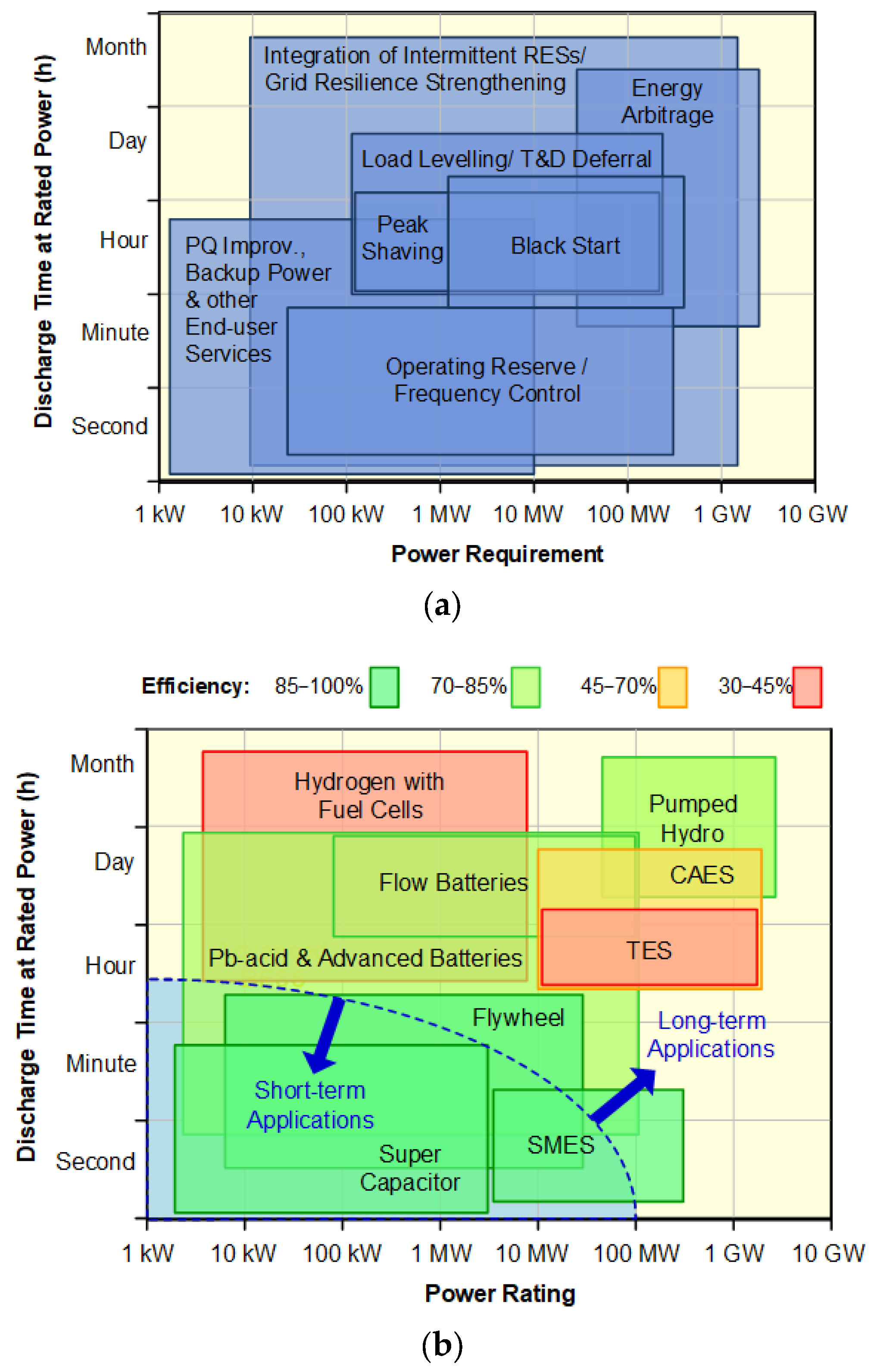
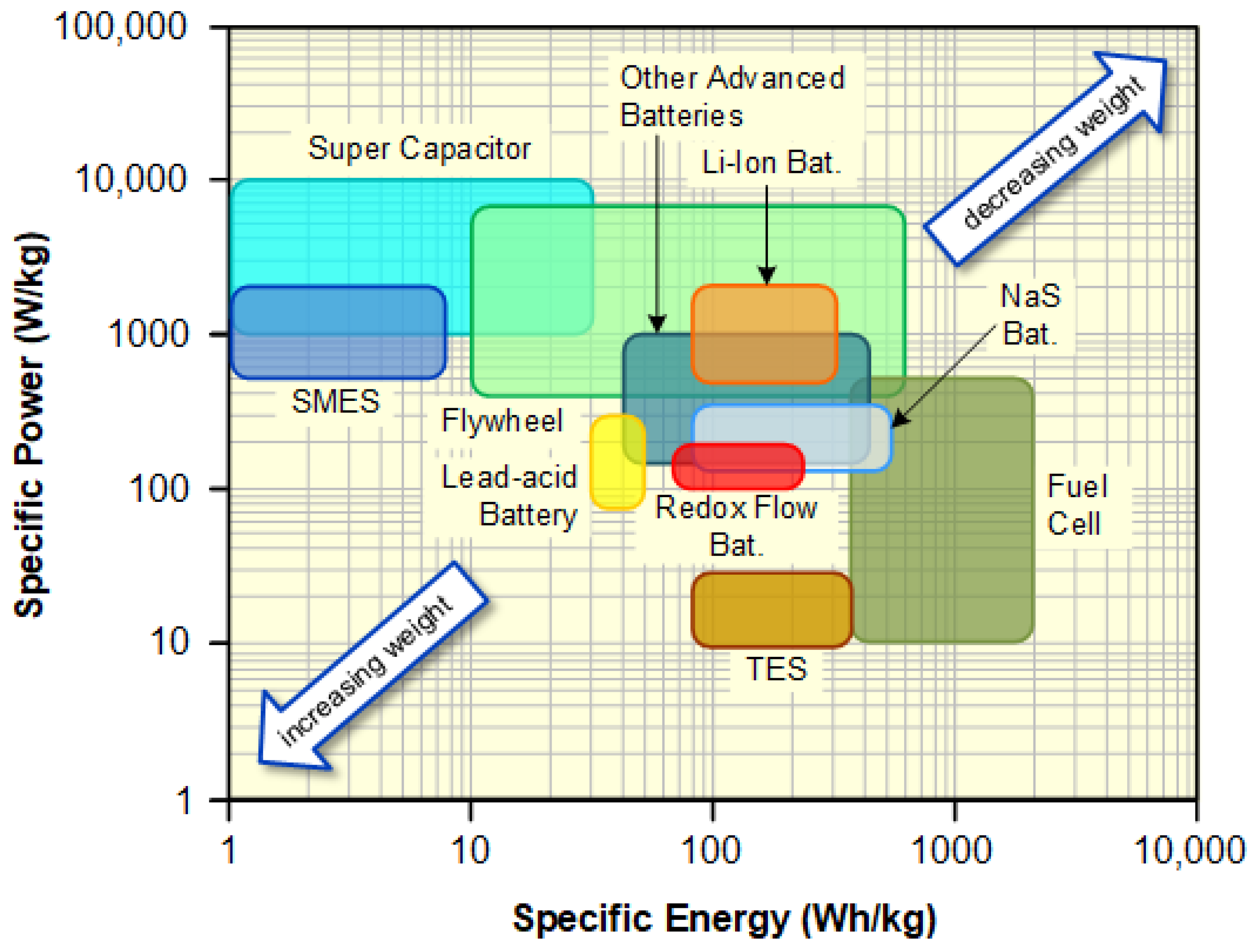
2.1. Energy Storage Systems

ESSs serve to convert electrical energy into various forms that can be stored and later reconverted into electricity as required. The classification of storage systems, as depicted in Figure 4, is primarily based on the type of energy stored within the system. Accordingly, ESSs can be categorized into mechanical, electrical, electrochemical, chemical, and thermal energy storage [25,26,27,28,29,30].
Figure 5 shows a comparison of power ratings/requirements and discharge time at rated power of energy storage technologies and their potential applications [25,29].
ESSs can be divided into two main types: power applications and energy applications. In general terms, power applications involve storage devices suitable for short-term applications, with short discharge times (seconds to several minutes, typically less than an hour), whereas energy applications include storage systems appropriate for long-term applications, with extended discharge times (usually more than an hour and up to several months).
Commonly, short-term applications require energy storage systems to supply energy immediately after activation, although they undergo a rapid discharge. The ESSs for these applications must have an energy-to-power ratio (energy capacity in kWh divided by the power rating in kW) of less than one hour. On the other side, the requirements of charge/discharge rates are high, and per the power application, the ESSs must perform a huge number of charge/discharge cycles per day.
Conversely, long-term applications do not need energy storage to supply energy instantly after activation, and the maximum duration of power delivery is longer than an hour. These required energy storage systems must have an energy-to-power ratio of more than one hour so they are able to supply power for several days or weeks (even months). On the other side, the requirements of charge/discharge rates are not high, and per the energy application, the ESSs hardly exceeds two full charge/discharge cycles per day.
Thus, energy storage applications may be appropriately categorized for both long and short duration and frequent and infrequent discharge. These are considered the most relevant characteristics for a preliminary assessment of ESS technologies [25].
In the same way, specific power (expressed in W/kg) and specific energy (Wh/kg) are also two parameters of great importance that indicate how much power and energy can be obtained per unit weight of the ESS.
These two properties play a major role, especially in transportation applications such as hybrid and electric vehicles (HEVs/EVs), where the weight of battery packs for these applications must be reduced to an acceptable fraction of the HEV/EV total weight. Figure 6 shows the comparison of specific power and specific energy of various ESS technologies. As can be seen, the higher the specific power and energy, the lighter the energy storage system.
The ESS technologies suitable for lightweight applications can be found in the top right corner of the figure. In contrast, the lower the specific power and energy, the heavier the energy storage system (these technologies are located in the bottom left corner). As can be seen, super capacitors, SMES, and flywheels are the technologies with the highest specific power, but they have low specific energy. In the same way, fuel cells have the highest specific energy, but they show a relatively moderate specific power. Most batteries are located in the middle levels in terms of specific power and specific energy, with Li-ion batteries having both high specific energy and high specific power. This explains the recent wide range of applications for Li-ion batteries, especially from portable electronic devices to transportation.
It can be straightforwardly inferred that the features of energy storage technologies must align with the requirements of the specific application under consideration to select the most suitable technology [25].
In the context of MGs, short-term applications are the pertinent qualifiers for ESSs. Within this domain, we observe that supercapacitors, flywheels, SMES (superconducting magnetic energy storage), and both lead–acid and advanced batteries demonstrate competence.
These types of technologies, due to their great response capacity and short-time access, are of special interest for applications in MGs with high penetration of non-conventional renewable generation. In this scenario, storage systems are necessary to counteract the high fluctuations of non-conventional renewable generation and demand, thus maintaining the balance of energy and power.
Furthermore, when appropriately coupled with power electronics interfaces and controllers, these ESSs are capable of furnishing the smart microgrid with active and reactive power independently, simultaneously, and with exceptional speed to regulate both f and V.
The regulation capacity is another mandatory subject of study in MGs due to the lack of inertial response, as most DGs are inverter-based resources. To overcome this issue, ESSs are necessary, as they can assume the task of a synchronous generator to emulate inertia via an adequate control scheme [10]. In context with the above and with the hierarchical control, Pb-acid and advanced batteries are employed at secondary and tertiary control levels, whereas flywheels are utilized at the primary control level.
Despite the fact that batteries possess the required speed to operate effectively at the primary level, the constant charging and discharging demanded by this level of control can potentially diminish the anticipated lifespan of the batteries. In contrast, this issue does not apply to flywheels, which is why that technology finds application at the primary level of control.

2.2. Custom Power Devices

Regarding CPDs (custom power devices), they are mainly divided into two groups: network reconfiguring type and compensating type, as depicted in Figure 7. These power electronic devices can be connected either in series or in parallel configurations. These devices allow for improved power transfer capability and rapid voltage control (an inherent feature of electronic devices). Furthermore, they contribute to increased stability margins during resilient contingencies [31,32].
Generally, CPDs employed in MGs due to the maturity reached by the technology are designed to regulate voltage at the three hierarchical levels of control. These devices include the SVC (static var compensator) and the DSTATCOM (distribution static compensator), both of which serve as reactive power sources to enhance and mitigate challenges associated with dynamic voltage stability in microgrids.

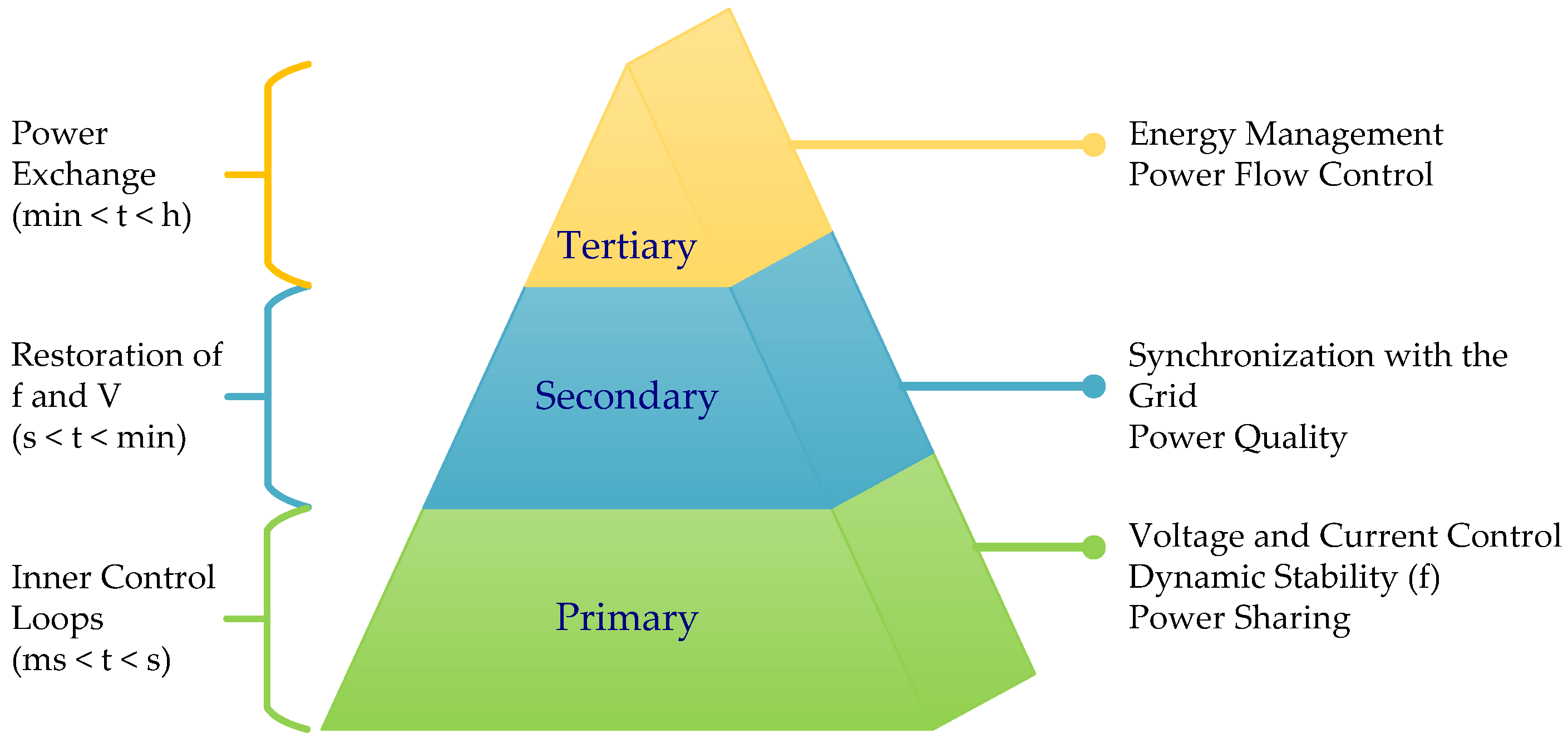
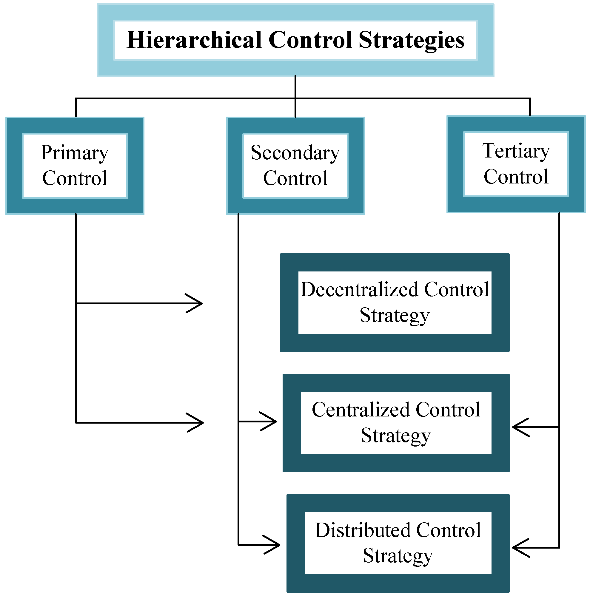
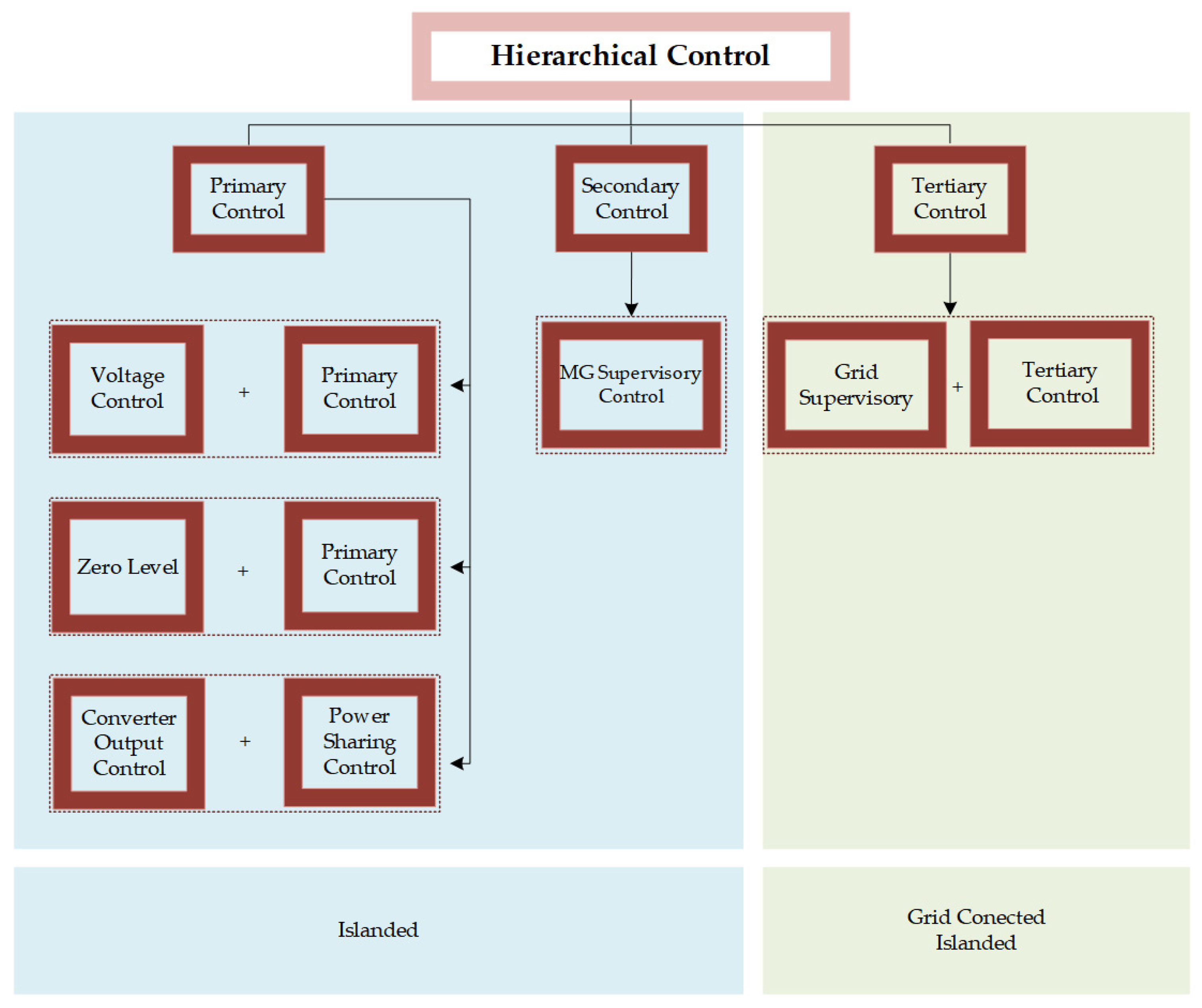
3. Hierarchical Control

As introduced in the previous section, MG control can be characterized as a three-level control: primary (first), secondary (second), and tertiary (third) [2,4,8,21,33,34,35,36,37,38]. Also, it can be found in the literature as a four-level control: voltage (first), primary (second), secondary (third), and tertiary (fourth) [39]; as zero (first), primary (second), secondary (third), and tertiary (fourth) [40]; or as converter output control (first), power sharing control (second), MG supervision control (third), and tertiary control (fourth) [41].
Studying the MG with three-level control is the most common approach since the four-level approach subdivides the functions of one hierarchy into two or assigns it another name, as shown in Figure 8. The following explains the basis of each level of operation.
The primary control level consists of a local variable control scheme, where MG stability in f and V is ensured; thus, it only functions in island mode. The secondary control level ensures that f and V are within acceptable values, restoring them to nominal values after the primary control has stabilized them. The secondary control, like the primary control, only operates when the MG is disconnected from the main grid. In the hierarchical control strategy, the optimal distribution management system and energy flow control take place at the tertiary control level [42]. This is the decision level at which the power exchange between the MG and the main grid is controlled, making it the only one enabled in both modes of operation. By applying an appropriate control architecture, the system becomes more flexible and expandable so that more DGs can be integrated [4]. In the field of control strategies, several approaches can be taken. One such approach is decentralized control, as shown in Figure 9a. This type of control uses local measurements that are processed by a unit known as a local controller (LC). Another approach is centralized control, as shown in Figure 9b, which relies on communication links to send commands from the supervisory control of the MG (central controller) to lower-level controllers [6]. Lastly, there is the distributed control, as shown in Figure 9c, which is characterized by the distribution of control responsibilities throughout the MG, with the DGs acting as autonomous agents that operate cooperatively to achieve global objectives [33,35,43,44,45].

3.1. Primary Control

The primary control is a critical component in the hierarchical structure of an MG, serving as the main control level. It has two primary functions: controlling the active power and voltage in island mode and regulating the frequency of the MG when the connection with the main grid is lost [8,46,47,48,49].
To achieve these objectives, the primary control must deal with inner voltage and current control loops as well as with f regulation and power sharing [41,50,51]. To achieve these objectives, different strategies can be implemented, including both centralized and decentralized approaches. Techniques based on droop control are widely used as a decentralized strategy, and they are the most common in practice [21]. In droop control, the converters act as voltage sources and adjust the reference voltage and frequency to stable values [52,53,54,55,56,57,58,59]. It is based on mimicking the synchronous generator by generating an intentional frequency deviation. In other words, it changes the frequency and amplitude of the voltage based on the load. Indeed, since the power electronic interface of DGs is inertia-less, a control that is able to adapt itself when the load changes has to be implemented. This can be achieved by adjusting the output voltage frequency and amplitude. An increase in the power demand implies a decrease in the voltage frequency or amplitude, based on whether the increase is in the active or reactive power, respectively. This technique is highly reliable and maximizes the distribution capacity of the MG, making it ideal for the operation of converters in parallel [15].
In addition to droop control, other communication-based techniques can be used, such as master–slave control, which is centralized but less frequently used compared to droop control [2,4]. Finally, according to the literature, the distributed control strategy is not studied at this level.
Overall, the primary control is a crucial aspect of MG operation, ensuring that the MG is stable and functions properly. The appropriate selection of control strategies depends on various factors, including the nature of the MG, the types of DGs used, and the specific requirements of the system.

3.2. Secondary Control

The second level of control in the hierarchical structure of an MG is responsible for addressing deviations in voltage and frequency in the MG. However, the secondary control only operates in island mode, similar to the primary control [2]. The main function of the secondary control is to compensate for the steady-state errors in voltage and frequency in the MG, ensuring that they are restored to their nominal values [60]. Additionally, in larger MGs with more than one bus, the secondary control is responsible for controlling the voltage profile along all the AC buses, keeping it within the operating limits.
Unlike the primary control, the secondary control uses communication systems that monitor large sectors to coordinate the actions of all generation units within a specified area. The response time of the secondary control is slower than that of the primary control, typically in the range of seconds to minutes [46]. The control strategies at this level are generally centralized and can also be distributed [61]. Commonly, centralized control is used in small MGs, whereas distributed schemes are used in larger ones [33].
The secondary control is responsible for ensuring that the MG operates stably and reliably, even during changes in power supply or load demand. It is designed to provide more fine-grained control than the primary control, with the ability to adjust voltage and frequency to correct any steady-state errors. Additionally, the secondary control is responsible for managing power flows between different parts of the MG, ensuring that there is enough power available for regulation to meet the needs of all loads.
The communication systems used in the secondary control allow for real-time monitoring and control of the MG, enabling operators to quickly respond to any changes in load or generation. However, since the secondary control is mostly centralized, it may be more susceptible to failures in communication or power supply disruptions.

3.3. Tertiary Control

The tertiary control level is responsible for optimizing the operation of the MG by establishing its interaction with the main grid through the control of active and reactive power references for each of the DGs. The optimization is usually based on economic criteria, which consider the relationship between demand and energy supply balance, along with the marginal generation cost of each unit of the DGs [2]. This level of control plays a crucial role in ensuring efficient and reliable operation of the MG, particularly in situations where the load demand and energy supply balance are constantly changing.
In grid-connected mode, the tertiary control level considers short-term load changes, generation forecasts, energy storage capacity, specific demand requirements, and price signals provided by the electricity market in analyzing MG operation. It optimizes the power output of the DGs to ensure that the overall cost of generation is minimized while meeting the demand requirements. In island mode, the tertiary control level is responsible for restoring the secondary control reserve and managing any potential congestion in the MG. It also manages the power injection according to the availability of resources and the demand requirements.
Due to the several functions performed by the tertiary control level, communication between the DGs is necessary for the connected and island modes of operation. This communication enables the DGs to coordinate their actions and ensure the optimization of the overall MG operation. The use of advanced communication systems and intelligent algorithms can further improve the efficiency and reliability of the tertiary control level [46].
In order to achieve optimal operation of an MG, an energy management system (EMS) is often employed [62,63]. The EMS is responsible for managing and optimizing the generation and consumption of energy within the MG, based on various criteria such as economic efficiency, environmental impact, and grid stability [64,65,66,67,68,69,70].
At the tertiary control level, the EMS is responsible for coordinating the various DGs within the MG, including renewable energy sources, energy storage systems, and backup generators, to ensure that the MG is operating efficiently and reliably. The EMS uses a variety of algorithms and optimization techniques to determine the optimal dispatch of power from each DG based on real-time supply-and-demand conditions.
In addition, the EMS monitors and forecasts the energy supply demand within the MG, taking into account factors such as weather patterns, load variability, and energy storage levels. This allows the EMS to predict any potential energy imbalances and to proactively adjust the DG dispatch to maintain a stable and reliable supply of energy. The EMS also plays a critical role in the interface between the MG and the main grid. It manages the connection and disconnection of the MG from the main grid and ensures that the MG operates within the grid code and regulatory requirements. This includes controlling the power flow between the MG and the main grid.
In addition, the economic optimization of the MG as seen before is highly dependent on the hierarchical structure and could be implemented considering the randomness of power generation and load, like in [71].
Overall, the EMS is an essential component of a well-designed MG, enabling efficient and reliable operation of the system while maximizing the benefits of the DGs within it.

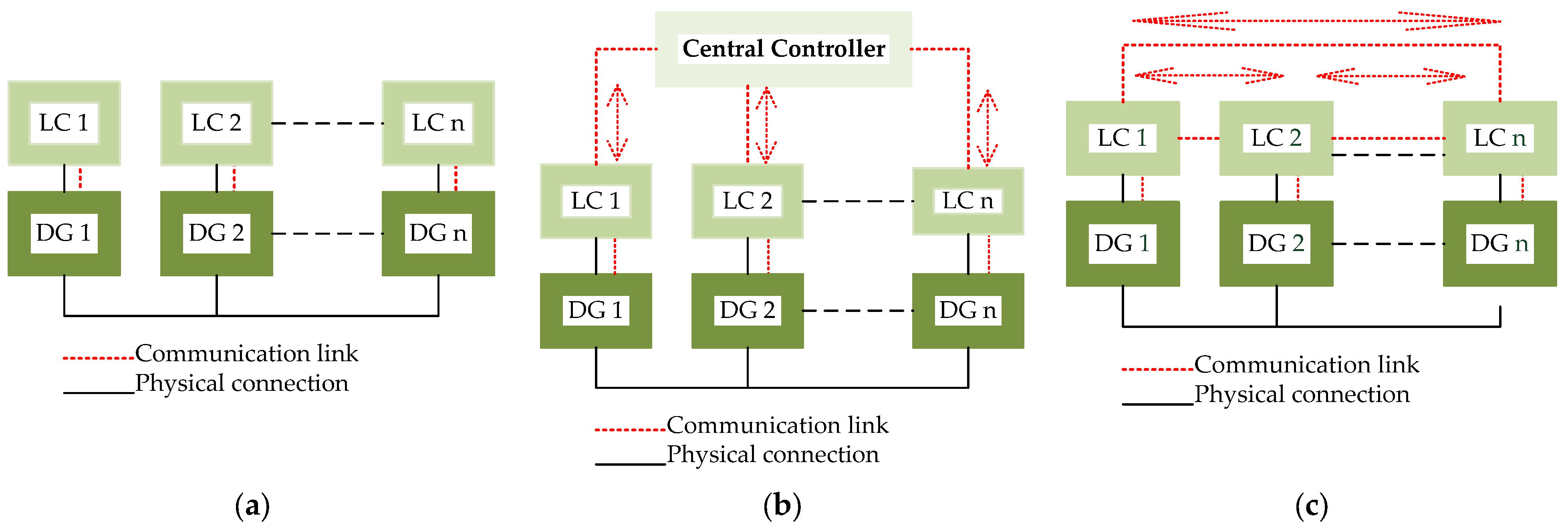
4. Decentralized Control Strategy

In isolated MGs, the control methods in which the DGs are controlled through an LC or independently, as shown in Figure 9a, and in which each controller acts using only its own measurements [4], as mentioned previously, are decentralized. This control strategy has the disadvantage of the LCs not having enough information about the operating state of other DGs since they operate independently. Nevertheless, it is considered the most reliable control method, as there is no need for communication links between different units. For large-scale MGs, this communication-free control strategy can be considered the best solution.
Decentralized control contributes to better energy management as the complexity of the electrical MG increases, controlling each unit separately [72]. In this control technique, the system can continue operating even if a connection between the DGs is lost. The advantages of decentralized control are that it is suitable for diverse, complex, and large-scale systems; is plug-and-play friendly and computationally inexpensive; and has the possibility of continuing to operate even if multiple points fail. The disadvantages of this control are the absence of a communication structure despite the need for synchronization among all DGs [4].

4.1. Decentralized Strategies for Primary Control
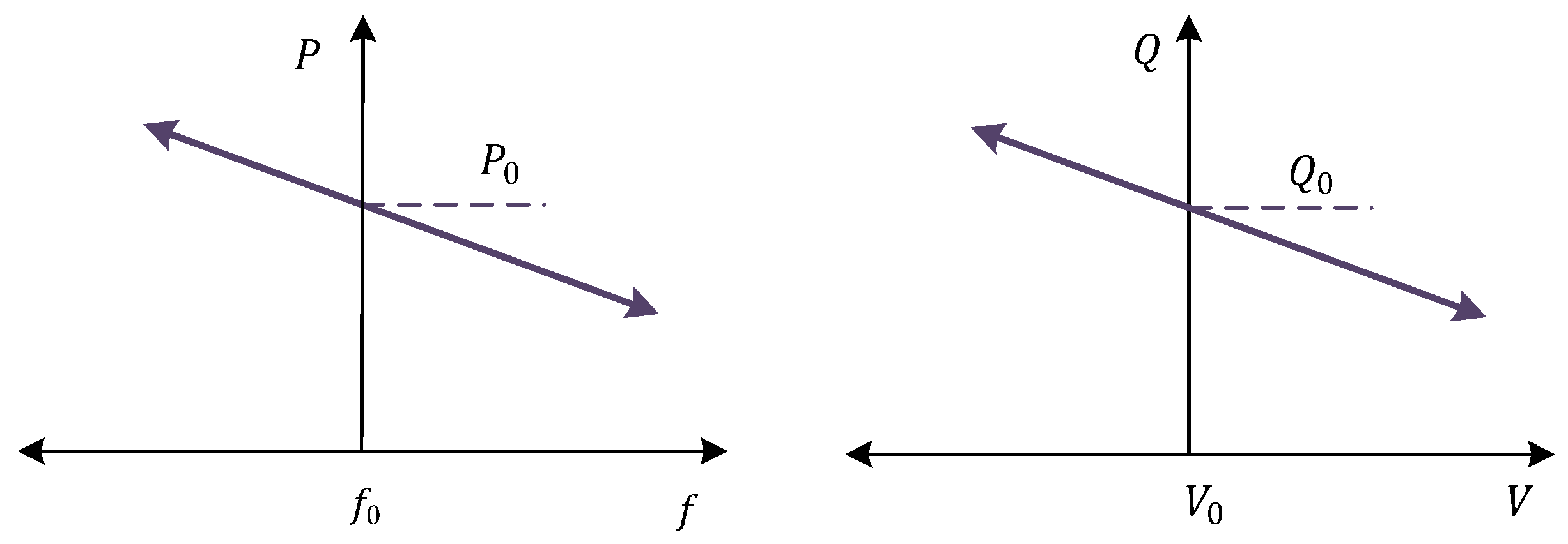
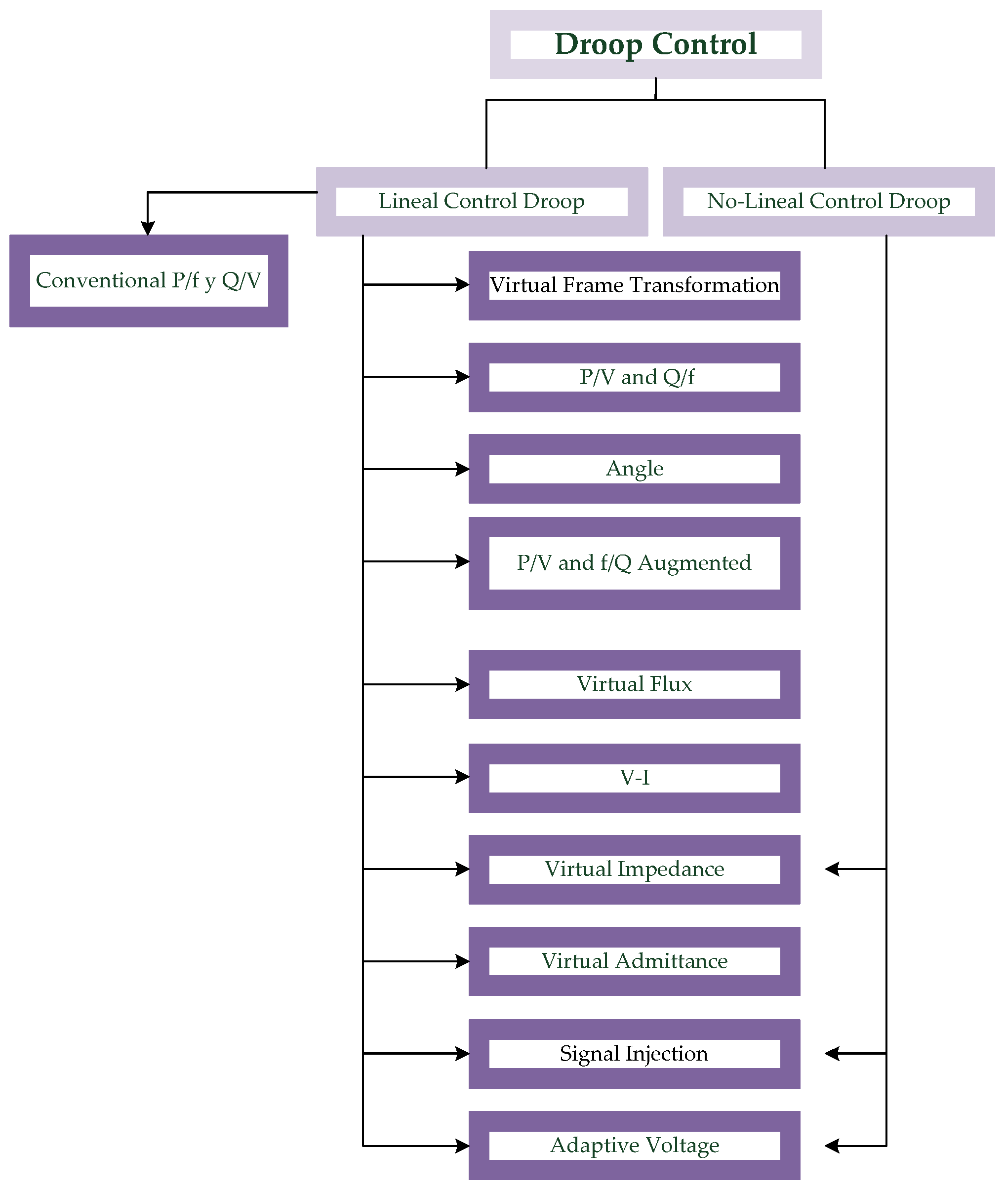
Droop Control

The most widely used and developed primary decentralized control strategy, due to its versatility, is droop control (see Table 1). This technique has even been studied for islanding detection, like in [73]. The main advantage of droop control is that it does not require a communication link to achieve power sharing (contribution of each DG). This provides flexibility and autonomy to the MG. Additionally, it allows for the inclusion of inverter-based generation in the MG since it is not exclusive for DGs like traditional synchronous machines [27,74]. When using this control technique, the parallel connection of DGs is permitted [2].
The basic idea behind droop control, as previously mentioned, is to emulate the behavior of a synchronous generator whose frequency decreases as active power consumption increases [2]. The characteristics of traditional droop control can be visualized in Figure 10 and can be explained as follows [84]:
As the frequency decreases from f 0 to f , the DG increases its active power from P 0 to P . A droop in frequency then indicates an increase in the active power of the system. The expressions of droop control for a network with inductive behavior can be written as follows [85]:
f f 0 = k p P P 0
V V 0 = k q Q Q 0
In Equation (1), the dependence between frequency and active power, as previously mentioned, can be seen. Equation (2) describes the dependence between voltage and reactive power. Here, k p and k q are the droop coefficients that represent the slopes of frequency and voltage drop, respectively, as seen in Figure 10.
The direct relationship between the droop control expressions and the physical characteristics of the MG is of great importance. Such is the case that when the MG is mainly resistive, as is often the case in low-voltage distribution networks, the equations change as follows:
V V 0 = k p P P 0
f f 0 = k q Q Q 0
In a conventional network, the large synchronous generators (SGs) provide significant rotating inertia in the system; hence, changes in grid frequency indicate a difference between the electrical power consumption and the mechanical input power. All generators act on frequency through their P/f droop controllers. However, in MGs, most DGs are converter-interfaced to the network. Consequently, islanded MGs lack the rotating inertia on which the conventional grid control is based, and consequently, a P/f droop control based on the inertia alone is not possible. However, in inductive networks, the power flow equations show an intrinsic relationship between the active power and the phase angle difference and between the reactive power and the grid voltage. As frequency dynamically determines the phase angle, P/f and Q/V droop controllers, analogous to those in the conventional network, can be used in the dispatchable DG units of inductive MGs.
In a traditional power system, a P(f) droop is implemented, where f is measured to determine the desired input power. In an MG with droops not depending on inertia, an analogous f(P) characteristic can be implemented as well [86]. That is, the AC power is measured to determine the frequency of the DG. However, droop control does have some drawbacks. One of these is the lack of communication infrastructure, which can make synchronization between all DGs difficult. To overcome this, extra synchronization control loops are needed if the operation of the MG includes parallel inverters. Nevertheless, droop control remains a popular and reliable choice for MG control due to its versatility and autonomy.
Since the beginning of electric power systems, droop control has been extensively studied in the control literature, resulting in numerous linear and nonlinear variants, which can be seen in Figure 11. Based on the physical characteristics or improvements in the performance of one function or another, one droop variant or another can be used [21,40,59]. Table 2 presents the advantages and disadvantages of some of the most used variants in the control mechanisms developed to solve problems in the MG.
At the secondary and tertiary levels, decentralized strategies are not studied due to the need for communication between DGs.

5. Centralized Control Strategy

The control methods with which DGs are managed by a central controller, as shown in Figure 9b, are called centralized control strategies. A centralized control strategy is designed with a basic control scheme that has been used in traditional power systems [4]. Typically, this has been the most used topology in secondary and tertiary controls due to the requirement of communication among the DGs, but it is also used in primary control [35]. In this strategy, the system has LCs corresponding to the management of each DG in the MG. Each LC has a communication link with the central controller. The central controller is unique and collects all the required information from the DGs, generating commands for each LC. In this control strategy, the LCs do not have any communication links with each other, and they cannot act independently.
The centralized scheme has the advantage of having the controllability of the entire system at a single point. Nevertheless, this characteristic adds the disadvantage of being susceptible to a failure in the controller or communication, which could lead to the collapse of the entire MG. Other drawbacks include poor performance that can arise in the system due to communication delays and measurement errors [61]. The most commonly used method that employs the use of a centralized strategy is master–slave control [4]. While centralized control has some drawbacks, it can be an effective solution in certain situations where communication is reliable and system stability is of utmost importance.

5.1. Centralized Control Strategies for Primary Control

Master–Slave Control

In MG control systems, the master–slave control strategy is a commonly used approach to manage the power output of DGs [87]. The basic idea of this strategy is to have one DG, usually the most powerful or the most reliable one, acting as the master and the other DGs acting as slaves [47]. The master is responsible for all of the calculations and provides the power, voltage, and frequency commands to the other DGs, acting as slaves.
This approach has several advantages, including simplicity, reliability, and scalability. It allows for easy integration of new DGs into the MG, and it is relatively easy to implement with simple communication protocols. Additionally, by having one DG acting as the master, the risk of conflicting control signals is reduced, which helps to maintain stability within the MG. However, there are also some potential drawbacks to the master–slave control strategy. One major concern is the single point of failure that comes with having one DG acting as the master. If the master fails, the entire MG could be at risk of destabilization. To counteract the disadvantage of network collapse if the master DG fails, a strategy called “priority rotation window,” which proposes random selection of the master, has been presented in the literature [8,47]. Additionally, this strategy does not allow for dynamic load balancing between the different DGs, which could lead to inefficiencies in power generation due to delays in the communication system that prevent the master from ordering the set points correctly.
Despite these limitations, the master–slave control strategy is still widely used in MG control systems, particularly in smaller, less complex MGs. It provides a simple, reliable, and cost-effective approach to managing DGs within an MG and is a good starting point for more advanced control strategies.

5.2. Centralized Control Strategies for Secondary Control

5.2.1. Master–Slave Control

In an MG, the secondary control is responsible for regulating the frequency and voltage levels within the system. In the master–slave control strategy for secondary control, the master generating unit is responsible for regulating the frequency and voltage levels in the MG. The master unit is typically the generator with the highest power output, and its power output is modulated to maintain the frequency and voltage levels at the set points [39]. The slave units follow the instructions of the master by delivering power in cases where the master unit cannot regulate the parameters by itself. By using the master unit to modulate the power output, the frequency and voltage levels can be kept within the desired range, even in the presence of load changes or other disturbances.
However, the master–slave control strategy for secondary control also has some limitations. For example, if the master unit fails or becomes disconnected from the MG, the entire system may become unstable or even collapse. Additionally, if the slave units are not properly synchronized with the master unit, they may inject power that is out of phase with the system, which can lead to instability and other problems. Therefore, it is important to carefully design and implement the master–slave control strategy for secondary control to ensure the reliable and stable operation of the MG.

5.2.2. Central Control and Supervision of Microgrid

Central control and supervision of the MG (MGCC) is a critical aspect for ensuring reliable and efficient operation. The central controller is an exclusive independent control and acts as the brain of the MG. It is responsible for monitoring and controlling all of the connected components, including generators, loads, energy storage systems, and power electronics [8,88,89]. One of the main functions of the central controller is to maintain the frequency and voltage of the MG within acceptable levels [90]. To achieve this, the controller receives information from the LC of each DG, which is responsible for regulating the output power of the generator based on the frequency and voltage measurements.
The central controller processes all of this information and decides which generator or generators should be responsible for restoring the frequency and voltage back to their nominal values. This decision is based on the availability of power from each generator, as well as other factors, such as the priority of the loads and the constraints of the MG.
In addition to maintaining the frequency and voltage, the central controller also performs other functions, such as load shedding, islanding detection, and re-synchronization. Load shedding involves disconnecting certain loads from the MG in case of a shortage of power, whereas islanding detection is the process of detecting when the MG has become disconnected from the main grid and switching it to island mode. Re-synchronization involves reconnecting the MG back to the main grid after a period of islanding.
Overall, central control and supervision is crucial to the reliable and efficient operation of an MG. This requires a sophisticated control system and advanced communication infrastructure to ensure seamless coordination and operation of all of the connected components.

5.3. Centralized Control Strategies for Tertiary Control

Central Grid Supervision Controller

This strategy is used in grid-connected mode to control the import or export of energy with the main grid [42]. In this case, the controller exchanges information with the distribution system operator to optimize operation of the MG. Economic criteria, resource availability, forecasting, the state of charge of storage systems, and local demand establish the power injection control commands for each of the DGs [8].
The central controller is always monitoring economic signals to determine whether to buy energy from the main grid or sell energy from the DGs in the MG.
This strategy can also be implemented in isolated mode, providing load balancing by setting the interaction of power with the main grid to zero.
As mentioned in previous sections, the control technique can be implemented using an EMS. An EMS has the ability to operate in both MG modes of operation by modifying the optimization problem restrictions and objective function [91].
Additionally, the controller implements strategies to increase the benefit of the MG using flexible strategies like the demand response approach.

6. Distributed Control Strategy

The concept of distributed control is an alternative approach to the centralized and decentralized control strategies in MG systems. In distributed control, there is no central controller, and each DG has its own LC that interacts with other LCs to maintain the MG stable operation [8]. This strategy is mostly used in islanded mode and can be implemented at both secondary and tertiary control levels [92]. The operation of DGs with this strategy corresponds to a distributed cooperative effort that depends on the method used.
One of the main advantages of distributed control is its robustness, as it can tolerate faults and failures in some components without causing catastrophic MG failures. In contrast, the centralized strategy has a common point of failure in the central controller. Distributed control is also scalable, allowing for easier changes to the MG, such as adding new DGs, energy storage systems, and loads without affecting the operation of other elements. Furthermore, it enables the plug-and-play operation of DGs, as in the decentralized strategy [4,35].
However, distributed control is not without its challenges. Communication delays and measurement errors can negatively impact its effectiveness [61]. To overcome these challenges, various methods have been developed. In the secondary control level, the multi-agent technique and its variants are commonly employed. In the tertiary control level, the following techniques are used: distributed power injection, distributed economic dispatch, the predictive control technique, the consensus technique, and the decomposition technique.
Overall, distributed control is a promising approach for MG control, offering numerous benefits, including flexibility, scalability, and robustness, but it also requires careful consideration of communication protocols, measurement accuracy, and control algorithm design to achieve optimal performance.

6.1. Distributed Strategies for Secondary Control

Multi-Agent Technique

The multi-agent technique has been widely used in MGs. In this technique, the DGs are considered autonomous agents with the ability to interact within the MG and change the conditions through their actions. The intelligence of each agent is characterized by its reaction to the environment, proactivity (goal-oriented action), and social skills (communication between agents) [4,21,34,93].
In this technique, the agents communicate with each other to exchange information about their current state and to coordinate their actions in order to achieve a common goal. The agents can also negotiate with each other to determine which agent is best suited to regulating the frequency and voltage at any given time. In ref. [94], a consensus fault-tolerant control that depends on the information transferring between MG neighbor agents through a graph communication network is used. This control method is highly effective at mitigating the fault effect using the multi-agent technique.
One of the challenges of the multi-agent technique is the design of the agent communication protocol, which should be efficient and reliable to ensure proper coordination among agents. Another challenge is the development of effective negotiation strategies, which should take into account the preferences and constraints of each agent.

6.2. Distributed Control Strategies for Tertiary Control

6.2.1. Distributed Power Injection

In the distributed power injection technique, the power to be injected by each DG is determined by measuring the average current demand of the loads and dividing it by the number of units. This method is advantageous in its simplicity, as it does not require advanced communication or control systems. However, it has some limitations, such as the lack of control over some types of DGs, particularly those that are dependent on renewable energy sources like solar. In such cases, the power output of the DG cannot be easily controlled, which can lead to imbalances in the MG. Thus, the distributed power injection technique may not be suitable for systems that require precise control and regulation of power output. Despite its limitations, this technique remains a valuable option for smaller-scale MGs or for situations where advanced control systems are not available or necessary [8].

6.2.2. Predictive Control Technique

The predictive control technique is a powerful approach that solves multivariable optimization problems using demand and generation forecasts with feedback mechanisms. It also handles the constraints of the power system, making it a versatile and effective method for power management [21,34,95]. This technique can ensure a fair and optimal distribution of power among the DG, making it particularly useful in MGs. One advantage of the predictive control technique is its ability to anticipate changes in power generation and demand and adjust accordingly, which can lead to significant improvements in the stability and efficiency of the MG. The changes in power or demand are addressed through DGs pre-set with a reserve or with DGs that can be susceptible to curtailment. The control commands are assigned by the local controllers in accordance with the type of technology of the DG and the availability of the forecasted primary source. Additionally, this technique can be combined with other control strategies, such as multi-agent systems, to further enhance the performance and reliability of the MG [96].

6.2.3. Consensus Technique

The consensus technique is a distributed optimization approach in which each DG follows a global objective function that is normally set up to minimize costs but can be adapted for another purposes. Consensus algorithms aim to ensure that all DGs have the same information state to achieve the best performance in the MG. The consensus technique is particularly useful when the DGs have different types of resources, such as wind and solar, and operate under different conditions. In such cases, a distributed approach that balances the different resources and operating conditions can improve the overall performance of the MG. The consensus technique can also handle uncertainties in the MG, such as changes in demand and generation. However, the performance of the consensus technique depends on the communication network between the DGs and the accuracy of the information exchange. Therefore, efficient communication protocols and reliable information exchange mechanisms are essential for the success of the consensus technique in an MG [4,21,34,61].

6.2.4. Distributed Economic Dispatch

The problem of centralized conventional dispatch can be solved in a distributed way through two approaches [35]:

Marginal Cost Consensus Approach

The marginal cost consensus approach involves estimating marginal costs and using consensus algorithms to solve the optimization problem.
The main idea behind this approach is to obtain a consensus on the marginal costs of each DG in order to allocate the total load demand in a fair and efficient manner. The marginal costs represent the additional cost required to generate an additional unit of electricity and are used to determine the optimal dispatch of the available resources.
To implement this approach, each DG estimates its own marginal cost and shares this information with the other DGs using a consensus algorithm. The algorithm is designed to ensure that all DGs converge to a common value for the marginal costs. Once a consensus is reached, the total load demand is allocated among the DGs based on their respective marginal costs.
This technique offers several advantages over the centralized approach, including greater flexibility and scalability. It also reduces the reliance on a central controller and the risk of a single point of failure. However, the approach may be affected by communication delays and measurement errors, which can lead to suboptimal solutions [97].

Distributed Gradient Method

The distributed gradient method approach is another technique for solving the centralized conventional dispatch problem in a distributed manner. Unlike the previous approach, in this method, the marginal costs are calculated, which requires more robust algorithms and a longer amount of convergence time. It also uses a power balance that has constrains related to the location of each DG. If a load is in the neighborhood of the DG, that load can be supplied by the DG, otherwise, the DG contribution is zero. Also, the power balance is predefined to achieve identical marginal costs in all of the DGs. This approach has the disadvantage of not being suitable for MGs with distributed line congestion.
The congestion problem is solved by including constraints related to line current capacity limits and maximum and minimum power outputs of DGs. Including the congestion problem takes more time to achieve the convergence of the solution, but it guarantees the proper dispatch of each DG [98].

6.2.5. Decomposition Technique

The decomposition technique is a control technique where the original optimization problem is divided into several subproblems, which are assigned to all the control agents and then iteratively solved until convergence. This approach reduces the computational burden and allows for parallel processing, improving the overall efficiency of the solution. Moreover, the communication requirements among the agents are reduced, making this technique suitable for large-scale systems. The subproblems are solved independently by each control agent, and their solutions are combined to obtain the final solution of the original problem [21].

7. Examples

To illustrate the hierarchical control, an AC MG was simulated in the environment of MatLab R2021a [99]. The MG consisted of three DC sources that had different power, as seen in Figure 12. It consisted of a storage system feeding converter 1, a photovoltaic system feeding converter 2, and a wind turbine system for converter 3. Every converter had a filter and a coupling transformer to connect them to the PCC. The three sources supplied two fixed RL and R loads and one variable load, as specified in Table 3.

7.1. Tertiary Control

As mentioned in previous sections, the tertiary control oversees energy management. This management for the example MG is visualized in Figure 13.
The strategy used for the EMS was the central grid supervision controller (CGSC), which correspond to the centralized control strategies. This strategy plans the day-ahead operation of the MG and controls the import or export of energy with the external grid. It takes into consideration all of the restrictions of the DGs as well as the economic and environmental considerations imposed to minimize the total cost of the MG.
The optimization problem follows a mixed integer linear programming approach. The objective function and some restrictions of the MG can be seen below:
M i n   C T O T = C W T + C P V + C B E S S + C G R I D
P G E N t = P G R I D t + P P V t + P W T t + P D I S t
P D E M t = P E X C t + P C H t + P L O A D t
P G E N t = P D E M t
X D I S t + X C H t 1
X g r i d t + X e x c t 1
S o C t + 1 = S o C t + η C H × T E m a x × P C H t η D I S × T E m a x × P D I S t
                                    P D I S t P B E S S m á x × X D I S t ,   P C H t P B E S S m á x × X C H t
P G R I D t P E x G M á x t × X g r i d t , P E X C t P E x G M á x t × X e x c t
S o C m i n S o C t × S o C m a x
In Equation (8), the power balance between the generation and consumption of energy considering the discharge and charge state of the battery as well as the export or import of energy with the external grid is set. Equations (9) and (10) are binary restrictions that indicate the state of charge (SoC) of the battery as well as the interaction of the MG with the main. In Equation (11), the SoC is modeled, and the final restrictions are for the SoC and the max power of the battery and external grid, respectively.
To estimate the energy production of the renewable generators, the CGSC used an artificial neuronal network (ANN). The ANN predicted the wind speed, temperature, and irradiance. With the variables mentioned before, the mathematical modeling was used to feed the optimization problem with P P V t and P W T t .
As seen in Figure 13, the controller resolved the optimization for the day-ahead problem and set the points of operation of each DG while regulating the state of charge of the storage system. During the entire 24 h, the controller effectively managed and maintained the balance between load and generation. If the energy production in the MG was insufficient to supply the load, the MG imported energy from the external grid. This was seen in the morning and night hours. If the MG generated more energy than was required by the local load, the MG exported energy to the external grid. This happened at noon and during certain hours of the early afternoon.

7.2. Primary and Secondary Control

The primary and secondary controls are intricately linked to the stability of the MG. To visualize the concepts discussed, a simulation was executed. To achieve this, an example of frequency/active power droop control implementation, aligning with the decentralized control strategies, is provided, along with a secondary control utilizing MG supervisory control (MGSC), which corresponds to the centralized control strategies.
The droop control can be expressed for each DG as:
f 1 f 0 = k p 1 P 1 P 01
f 2 f 0 = k p 2 P 2 P 02
f 3 f 0 = k p 3 P 3 P 03
From Equations (15)–(17), it is possible to derive that, once the frequency regulation is completed and a common MG frequency is achieved, the following terms are equal:
k p 1 P 1 P 01 = k p 2 P 2 P 02 = k p 3 P 3 P 03
Equation (18) shows that there is a close relationship between the droop control coefficient and the supplied active power of each DG. In fact, if all of the DGs are implemented with the same droop control coefficient, perfect power sharing is achieved.
Before the simulation, the MG was disconnected from the PCC to analyze the island mode.
To illustrate the scenario, the three DGs were operated in a droop control, and the experimental results are presented in Figure 14.
The black start began at t = 0 with the connection of the three DGs. At t = 0 , the load was the sum of the two fixed loads of the table (450 kW and 50 kVAR). The three DGs supplied the load with the power sharing of the droop control. As a consequence of the droop, the frequency deviated from the nominal and convergence to a stabilized value in around 1 s, as can be seen in the zoomed-in window in Figure 14b. After the transient response, a global frequency was reached at t = 2 s. As mentioned in the theory before, the droop control method consists of subtracting a proportional part of the active power from a frequency reference to emulate a virtual inertia, which guarantees the convergence of a common deviated frequency (with respect to the nominal value) on the MG.
At t = 2.5 , the load was augmented by the connection of the variable load and the three DGs supplied the load, stepping up their active power set points. The delivered power of each DG followed the laws of the droop and reached a stable contribution, as illustrated in the zoomed-in image of Figure 14a. Also, as can be observed, the frequency of the three DGs decreased and reached a steady state after around 2 s (see the zoom-in part to the right in Figure 14b).
For the secondary control, the frequency/active power control can be expressed mathematically as follows:
f = f 0 k p P P o + δ
where δ is the term of the secondary control that performs the desired correction; thus, the frequency can be adjusted, as shown in the Figure 15.
The MGCC measured the variable of interest, executed the required calculations, and sent the secondary terms to each DG.
In the simulation at t = 5.5 s, the secondary control was enabled. The three DGs participated in restoring the value of the frequency to the nominal by injecting active power, as can be seen in Figure 14a,b.
The new steady state of the frequency was finally reached in less than 3 s.

8. Comments and Discussion

At the primary control level, the decentralized strategy using droop control has improved over the years, starting with conventional droop, which does not consider the management of nonlinear loads, to virtual impedance droop, signal injection, and adaptive voltage droop, which do. In ref. [47] (published in 2020), it is stated that adaptive voltage droop cannot be used for this purpose, but in [20] (published in 2021), assisted by [100], it is demonstrated that this variant of droop can indeed handle nonlinear loads; this discussion demonstrates the need for a detailed review. The interest in the study of this topic, combined with technological developments and supported by well-established concepts such as droop control, allows for works such as [101], where the frequency and voltage droop coefficients are calculated using fuzzy logic to objectively control the first level in the hierarchical approach, and studies like [102], where deep reinforcement learning is used. Additionally, the use of CPDs, being novel devices that improve the performance of MG control in resilient contingencies, is expected to be an interesting topic for future studies in the area of emerging networks [31].
As shown in the example, the two first levels are only activated when the MG is isolated. This is because in the grid-connected mode, the regulation of frequency and voltage is a task for the external grid. In recent years, these control levels for MGs have been employed for ancillary services, but there is no standard that rules the requirements of power or energy quality. Currently, great effort is being made to finally use MGs to not only regulate their own subsystems but also to support the external grid with the use of several control strategies in the hierarchical structure.
Figure 2 is of particular interest because it shows that certain control strategies cannot be implemented at certain levels of control. Even though some authors have shown that a distributed strategy could be used for primary control, those studies do not explain the need for fast and extremely expensive communication systems for this purpose [35]. At the secondary control level, the communication among DGs is a rule in the literature, and even though there are studies like [76] that aim to be communication-less, the authors conclude that this approach requires complex analysis of the topology and loads of the MG, representing a drawback for flexibility. They also show that it is susceptible to instabilities produced by clock drifts in power converters. The tertiary level is the only one that is well stablished as a communication-dependent level, and no works have been presented that aim to show the opposite.

9. Conclusions

In distribution networks, the inclusion of multiple DGs requires the development of control strategies to manage power flows within the MG or between the MG and the traditional grid. The hierarchical approach with three levels (primary, secondary, tertiary) and different control strategies (decentralized, centralized, distributed) has proven to be very efficient in achieving the set objectives. The primary control ensures reliable and safe operation while maintaining voltage and frequency stability. This control is mostly decentralized, functional only in islanded mode, and implemented using droop control. The secondary control is applied to optimize the quality of MG energy while minimizing voltage and frequency deviations. It is used in centralized and distributed approaches, with applications in autonomous mode, although voltage regulation is a task that responds to a local phenomenon, and it could also be a function to be performed in grid-connected mode. The tertiary control is used to achieve economic optimization based on energy costs and the electricity market. By using information, it can be used with centralized or distributed strategies. This control is the only one that performs tasks in both modes of MG operation.
Through a review and a comprehensive descriptive approach, this study allows for a pedagogical understanding of hierarchical control in MGs. As a result, it is possible to segment the different levels of control according to the mode of operation of the MG to delve into the different control strategies. In the final part, the examples create a binding environment between theory and practice that allows the concepts studied to be consolidated.

Author Contributions

Conceptualization, P.A.C. and M.M.; methodology, P.A.C., M.M. and M.G.M.; formal analysis, P.A.C. and M.M.; investigation, P.A.C. and M.M.; writing—original draft preparation, P.A.C., M.M. and M.G.M.; writing—review and editing, P.A.C., M.M. and M.G.M.; visualization, P.A.C.; supervision, P.E.M.; project administration, M.M. and M.G.M. All authors have read and agreed to the published version of the manuscript.

Funding

This research received no external funding.

Institutional Review Board Statement

Not applicable.

Informed Consent Statement

Not applicable.

Data Availability Statement

Not applicable.

Acknowledgments

This work received partial funding from the German Academic Exchange Service (DAAD), the National Scientific and Technical Research Council (CONICET) of Argentina, the National University of San Juan (UNSJ) in Argentina, the Secretary of Science and Technology of the Government of San Juan Province in Argentina, and the Ministry of Science, Technology, and Innovation of Argentina.

Conflicts of Interest

The authors declare no conflict of interest.

Abbreviations

ACAlternating current
ANNArtificial neuronal network
BESSBattery energy storage system
CPDCustom power device
C P V Photovoltaic power cost
C W T Wind turbine power cost
CGSCCentral grid supervisory controller
C T O T Total cost
C B E S S Battery cost
C G R I D Grid power cost
DCDirect current
DGDistributed generator
DSTATCOMDistribution static compensator
ESSEnergy storage system
ENSEnergy not supplied
EMSEnergy management system
E m a x Max energy
fFrequency
HEV/EVHybrid and electric vehicle
ICurrent
k p Active power droop coefficient
k q Reactive power droop coefficient
kWKilowatt
kVARKilovolt ampere reactive
LCLocal controller
MGMicrogrid
MGCCMicrogrid central controller
MGSCMicrogrid supervisory control
PActive power
PCCPoint of common coupling
P C H Charge power
P P V Photovoltaic power
P W T Wind turbine power
P B E S S Battery power
P D E M Demanded power
P D I S Discharge power
P E X C Excess power
P G E N Generated power
P G R I D Grid power
P L O A D Load power
QReactive power
SOCState of charge
SVCStatic var compensator
SMESSuperconducting magnetic energy storage
TTime
VVoltage
X C H Charge binary variable
X D I S Discharge binary variable
X e x c Excess binary variable
X g r i d Grid binary variable
η C H Battery charge efficiency
η D I S Battery discharge efficiency

References

  1. Cardenas, P.; Martinez, M.; Molina, M. Estrategias de Control de Microrredes en CA: Una Revisión Breve. In Proceedings of the 2022 IEEE Biennial Congress of Argentina, ARGENCON 2022, San Juan, Argentina, 7–9 September 2022; Institute of Electrical and Electronics Engineers Inc.: Piscataway, NJ, USA, 2022. [Google Scholar] [CrossRef]
  2. Refaat, S.S.; Ellabban, O.; Bayhan, S.; Abu-Rub, H.; Blaabjerg, F.; Begovic, M.M. Microgrids: State-of-the-Art and Future Challenges. In Smart Grid and Enabling Technologies; Wiley-IEEE Press: New York, NY, USA, 2021; pp. 141–163. [Google Scholar] [CrossRef]
  3. Molina, M.G.; Mercado, P.E. Renewable Energy Technologies for Microgrids. In Renewable Energy Technologies for Microgrids; Zambroni de Souza, A.C., Castilla, M., Eds.; Springer: Berlin/Heidelberg, Germany, 2019; pp. 27–67. [Google Scholar] [CrossRef]
  4. Altin, N.; Eyimaya, S.E. A Review of Microgrid Control Strategies. In Proceedings of the 10th IEEE International Conference on Renewable Energy Research and Applications, ICRERA 2021, Istanbul, Turkey, 8–21 September 2022; Institute of Electrical and Electronics Engineers Inc.: Piscataway, NJ, USA, 2021; pp. 412–417. [Google Scholar] [CrossRef]
  5. Zhang, D.; Fletcher, J. Operation of Autonomous AC Microgrid at Constant Frequency and with Reactive Power Generation from Grid-forming, Grid-supporting and Grid-feeding Generators. In Proceedings of the TENCON 2018—2018 IEEE Region 10 Conference, Jeju Island, Republic of Korea, 28–31 October 2018. [Google Scholar] [CrossRef]
  6. Rizzato Lede, A.M.; Molina, M.G.; Martínez, M.; Mercado, P.E. Microgrid Architectures for Distributed Generation: A Brief Review. In Proceedings of the 2017 IEEE PES Innovative Smart Grid Technologies Conference—Latin America (ISGT Latin America), Quito, Ecuador, 20–22 September 2017; Institute of Electrical and Electronics Engineers Inc.: Piscataway, NJ, USA, 2017. [Google Scholar] [CrossRef]
  7. de Souza, A.C.Z.; Portelinha, F.M.; De Nadai, B.; Oliveira, D.Q.; Marujo, D. Overview on microgrids: Technologies, control and communications. In Sustainable Development in Energy Systems; Springer International Publishing: Berlin/Heidelberg, Germany, 2017; pp. 1–18. [Google Scholar] [CrossRef]
  8. Alfergani, A.; Alfaitori, K.A.; Khalil, A.; Buaossa, N. Control strategies in AC microgrid: A brief review. In Proceedings of the 2018 9th International Renewable Energy Congress, IREC 2018, Hammamet, Tunisia, 20–22 March 2018; Institute of Electrical and Electronics Engineers Inc.: Piscataway, NJ, USA, 2018; pp. 1–6. [Google Scholar] [CrossRef]
  9. Unamuno, E.; Barrena, J.A. Equivalence of primary control strategies for AC and DC microgrids. Energies 2017, 10, 91. [Google Scholar] [CrossRef]
  10. Ahmed, K.; Seyedmahmoudian, M.; Mekhilef, S.; Mubarak, N.M.; Stojcevski, A. A Review on Primary and Secondary Controls of Inverter-interfaced Microgrid. State Grid Electric Power Research Institute 1 September 2021. J. Mod. Power Syst. Clean Energy 2021, 9, 969–985. [Google Scholar] [CrossRef]
  11. Li, S.; Oshnoei, A.; Blaabjerg, F.; Anvari-Moghaddam, A. Hierarchical Control for Microgrids: A Survey on Classical and Machine Learning-Based Methods. Sustainability 2023, 15, 8952. [Google Scholar] [CrossRef]
  12. Tamrakar, U.; Shrestha, D.; Maharjan, M.; Bhattarai, B.P.; Hansen, T.M.; Tonkoski, R. Virtual inertia: Current trends and future directions. Appl. Sci. 2017, 7, 654. [Google Scholar] [CrossRef]
  13. Fekkak, B.; Menaa, M.; Boussahoua, B. Control of transformerless grid-connected PV system using average models of power electronics converters with MATLAB/Simulink. Sol. Energy 2018, 173, 804–813. [Google Scholar] [CrossRef]
  14. Aragon-Aviles, S.; Trivedi, A.; Williamson, S.S. Smart power electronics-based solutions to interface solar-photovoltaics (pv), smart grid, and electrified transportation: State-of-the-art and future prospects. Appl. Sci. 2020, 10, 4988. [Google Scholar] [CrossRef]
  15. Khan, M.Y.A.; Liu, H.; Yang, Z.; Yuan, X. A comprehensive review on grid connected photovoltaic inverters, their modulation techniques, and control strategies. Energies 2020, 13, 4185. [Google Scholar] [CrossRef]
  16. Hassaine, L.; Olias, E.; Quintero, J.; Salas, V. Overview of power inverter topologies and control structures for grid connected photovoltaic systems. Renew. Sustain. Energy Rev. 2014, 30, 796–807. [Google Scholar] [CrossRef]
  17. Mahrouch, A.; Ouassaid, M. De-loaded Low-Voltage Ride-Through control and Primary Frequency Control for AC-Microgrid based PMSG Enhanced by Battery. In Proceedings of the 2021 4th International Symposium on Advanced Electrical and Communication Technologies, ISAECT 2021, Alkhobar, Saudi Arabia, 6–8 December 2021; Institute of Electrical and Electronics Engineers Inc.: Piscataway, NJ, USA, 2021. [Google Scholar] [CrossRef]
  18. Stynski, S.; Luo, W.; Chub, A.; Franquelo, L.G.; Malinowski, M.; Vinnikov, D. Utility-Scale Energy Storage Systems: Converters and Control. IEEE Ind. Electron. Mag. 2020, 14, 32–52. [Google Scholar] [CrossRef]
  19. Hernandez-Alvidrez, J.; Darbali-Zamora, R.; Flicker, J.D.; Shirazi, M.; Vandermeer, J.; Thomson, W. Using Energy Storage-Based Grid Forming Inverters for Operational Reserve in Hybrid Diesel Microgrids. Energies 2022, 15, 2456. [Google Scholar] [CrossRef]
  20. Liu, Q.; Caldognetto, T.; Buso, S. Review and Comparison of Grid-Tied Inverter Controllers in Microgrids. In IEEE Transactions on Power Electronics; Institute of Electrical and Electronics Engineers Inc.: Piscataway, NJ, USA, 2020; pp. 7624–7639. [Google Scholar] [CrossRef]
  21. Sahoo, A.K.; Mahmud, K.; Crittenden, M.; Ravishankar, J.; Padmanaban, S.; Blaabjerg, F. Communication-less primary and secondary control in inverter-interfaced AC microgrid: An overview. IEEE J. Emerg. Sel. Top. Power Electron. 2021, 9, 5164–5182. [Google Scholar] [CrossRef]
  22. Hirsch, A.; Parag, Y.; Guerrero, J. Microgrids: A review of technologies, key drivers, and outstanding issues. Renew. Sustain. Energy Rev. 2018, 90, 402–411. [Google Scholar] [CrossRef]
  23. Faghihi, T.; Sabzi, S. Investigation of Microgrid Hierarchical Control and Structure. Adv. Model. Anal. C 2020, 75, 1–8. [Google Scholar] [CrossRef]
  24. Nasir, M.; Bansal, R.; Elnady, A. A Review of Various Neural Network Algorithms for Operation of AC Microgrids; Institute of Electrical and Electronics Engineers (IEEE): Piscataway, NJ, USA, 2022; pp. 1–7. [Google Scholar] [CrossRef]
  25. Marcelo, G.M. Grid Energy Storage Systems. In Power Electronics in Renewable Energy Systems and Smart Grid: Technology and Applications; Bimal, K.B., Ed.; Wiley-IEEE Press: Hoboken, NJ, USA, 2019; pp. 495–583. [Google Scholar] [CrossRef]
  26. Nazaripouya, H.; Chung, Y.-W.; Akhil, A. Energy Storage in microgrids: Challenges, applications and research need. Int. J. Energy Smart Grid 2019, 3, 60–70. [Google Scholar] [CrossRef]
  27. Georgious, R.; Refaat, R.; Garcia, J.; Daoud, A.A. Review on energy storage systems in microgrids. Electronics 2021, 10, 2134. [Google Scholar] [CrossRef]
  28. Faisal, M.; Hannan, M.A.; Ker, P.J.; Hussain, A.; Mansor, M.B.; Blaabjerg, F. Review of energy storage system technologies in microgrid applications: Issues and challenges. IEEE Access 2018, 6, 35143–35164. [Google Scholar] [CrossRef]
  29. Molina, M.G. Energy Storage and Power Electronics Technologies: A Strong Combination to Empower the Transformation to the Smart Grid. Proc. IEEE 2017, 105, 2191–2219. [Google Scholar] [CrossRef]
  30. Mitali, J.; Dhinakaran, S.; Mohamad, A.A. Energy storage systems: A review. Energy Storage Sav. 2022, 1, 166–216. [Google Scholar] [CrossRef]
  31. Paredes, L.A.; Molina, M.G.; Serrano, B.R. Resilient microgrids with FACTS technology. In Proceedings of the 2020 IEEE PES Transmission and Distribution Conference and Exhibition—Latin America, T and D LA 2020, Montevideo, Uruguay, 21 September–2 October 2020; Institute of Electrical and Electronics Engineers Inc.: Piscataway, NJ, USA, 2020. [Google Scholar] [CrossRef]
  32. Paredes, L.A.; Serrano, B.R.; Molina, M.G. FACTS Technology to Improve the Operation of Resilient Microgrids. In Proceedings of the 2019 FISE-IEEE/CIGRE Conference—Living the Energy Transition, FISE/CIGRE 2019, Medellín, Colombia, 4–6 December 2019; Institute of Electrical and Electronics Engineers Inc.: Piscataway, NJ, USA, 2019. [Google Scholar] [CrossRef]
  33. Ahmed, M.; Meegahapola, L.; Vahidnia, A.; Datta, M. Stability and Control Aspects of Microgrid Architectures—A Comprehensive Review. IEEE Access 2020, 8, 144730–144766. [Google Scholar] [CrossRef]
  34. Sahoo, S.K.; Sinha, A.K.; Kishore, N.K. Control Techniques in AC, DC, and Hybrid AC-DC Microgrid: A Review. IEEE J. Emerg. Sel. Top. Power Electron. 2018, 6, 738–759. [Google Scholar] [CrossRef]
  35. Espina, E.; Llanos, J.; Burgos-Mellado, C.; Cárdenas-Dobson, R.; Martínez-Gómez, M.; Sáez, D. Distributed control strategies for microgrids: An overview. IEEE Access 2020, 8, 193412–193448. [Google Scholar] [CrossRef]
  36. Mohammed, A.; Refaat, S.S.; Bayhan, S.; Abu-Rub, H. AC Microgrid Control and Management Strategies: Evaluation and Review. IEEE Power Electron. Mag. 2019, 6, 18–31. [Google Scholar] [CrossRef]
  37. Mohammadi, F.; Mohammadi-Ivatloo, B.; Gharehpetian, G.B.; Ali, M.H.; Wei, W.; Erdinc, O.; Shirkhani, M. Robust Control Strategies for Microgrids: A Review. IEEE Syst. J. 2022, 16, 2401–2412. [Google Scholar] [CrossRef]
  38. Khayat, Y.; Guerrero, J.M.; Bevrani, H.; Shafiee, Q.; Heydari, R.; Naderi, M.; Dorfler, F.; Fathi, M.; Blaabjerg, F.; Dragicevic, T.; et al. On the Secondary Control Architectures of AC Microgrids: An Overview. IEEE Trans. Power Electron. 2020, 35, 6482–6500. [Google Scholar] [CrossRef]
  39. Alsafran, A. Literature Review of Power Sharing Control Strategies in Islanded AC Microgrids with Nonlinear Loads. In Proceedings of the 2018 IEEE PES Innovative Smart Grid Technologies Conference Europe, ISGT-Europe 2018, Sarajevo, Bosnia and Herzegovina, 21–25 October 2018; Institute of Electrical and Electronics Engineers Inc.: Piscataway, NJ, USA, 2018. [Google Scholar] [CrossRef]
  40. Poonahela, I.; Bayhan, S.; Abu-Rub, H.; Begovic, M.; Shadmand, M. On Droop-based Voltage and Frequency Restoration Techniques for Islanded Microgrids. In Proceedings of the IECON Proceedings (Industrial Electronics Conference), Singapore, 16–19 October 2023; IEEE Computer Society: Washington, DC, USA, 2021. [Google Scholar] [CrossRef]
  41. Kzaviri, S.M.; Pahlevani, M.; Jain, P.; Bakhshai, A. A review of AC microgrid control methods. In Proceedings of the 2017 IEEE 8th International Symposium on Power Electronics for Distributed Generation Systems, PEDG 2017, Florianópolis, Brazil, 17–20 April 2017; Institute of Electrical and Electronics Engineers Inc.: Piscataway, NJ, USA, 2017. [Google Scholar] [CrossRef]
  42. Vasquez, J.; Guerrero, J.; Miret, J.; Castilla, M.; Garcia De Vicuna, L. Hierarchical control of intelligent microgrids. IEEE Ind. Electron. Mag. 2010, 4, 23–29. [Google Scholar] [CrossRef]
  43. Fahad, S.; Goudarzi, A.; Xiang, J. Demand management of active distribution network using coordination of virtual synchronous generators. IEEE Trans. Sustain. Energy 2021, 12, 250–261. [Google Scholar] [CrossRef]
  44. Uddin, M.; Mo, H.; Dong, D.; Elsawah, S.; Zhu, J.; Guerrero, J.M. Microgrids: A review, outstanding issues and future trends. Energy Strat. Rev. 2023, 49, 101127. [Google Scholar] [CrossRef]
  45. Khayat, Y.; Naderi, M.; Shafiee, Q.; Batmani, Y.; Fathi, M.; Guerrero, J.M.; Bevrani, H. Decentralized optimal frequency control in autonomous microgrids. IEEE Trans. Power Syst. 2019, 34, 2345–2353. [Google Scholar] [CrossRef]
  46. Rocabert, J.; Luna, A.; Blaabjerg, F.; Rodríguez, P. Control of power converters in AC microgrids. IEEE Trans. Power Electron. 2012, 27, 4734–4749. [Google Scholar] [CrossRef]
  47. Fernando Manuel, L.B. Stability Analysis on the Primary Control in Islanded AC Microgrids. 2019. Available online: www.utp.edu.co (accessed on 7 September 2022).
  48. Zhao, Y.; Gao, F.; Yu, J.; Zhang, B. An Enhanced Primary and Secondary Control Method for Three Phase VSCs. In Proceedings of the 2020 IEEE 11th International Symposium on Power Electronics for Distributed Generation Systems, PEDG 2020, Dubrovnik, Croatia, 8–11 June 2020; Institute of Electrical and Electronics Engineers Inc.: Piscataway, NJ, USA, 2020; pp. 566–572. [Google Scholar] [CrossRef]
  49. Mestriner, D.; Rosini, A.; Xhani, I.; Bonfiglio, A.; Procopio, R. Primary Voltage and Frequency Regulation in Inverter Based Islanded Microgrids through a Model Predictive Control Approach. Energies 2022, 15, 5077. [Google Scholar] [CrossRef]
  50. Rathore, B.; Srivastava, L.; Gupta, N. A Comprehensive Study on AC Microgrid Control Strategies at Primary Control Level. In Intelligent Computing Applications for Sustainable Real-World Systems; Springer: Berlin/Heidelberg, Germany, 2020; Volume 13, pp. 488–499. [Google Scholar] [CrossRef]
  51. Guerrero, J.M.; Vasquez, J.C.; Matas, J.; De Vicuña, L.G.; Castilla, M. Hierarchical control of droop-controlled AC and DC microgrids—A general approach toward standardization. IEEE Trans. Ind. Electron. 2011, 58, 158–172. [Google Scholar] [CrossRef]
  52. Zhang, H.; Xiang, W.; Lin, W.; Wen, J. Grid Forming Converters in Renewable Energy Sources Dominated Power Grid: Control Strategy, Stability, Application, and Challenges. J. Mod. Power Syst. Clean Energy 2021, 9, 1239–1256. [Google Scholar] [CrossRef]
  53. Li, Y.; Gu, Y.; Green, T. Revisiting Grid-Forming and Grid-Following Inverters: A Duality Theory. IEEE Trans. Power Syst. 2022, 37, 4541–4554. [Google Scholar] [CrossRef]
  54. Pawar, B.; Batzelis, E.; Chakrabarti, S.; Pal, B. Grid-Forming Control for Solar PV Systems with Power Reserves. IEEE Trans. Sustain. Energy 2021, 12, 1947–1959. [Google Scholar] [CrossRef]
  55. Han, H.; Hou, X.; Yang, J.; Wu, J.; Su, M.; Guerrero, J.M. Review of power sharing control strategies for islanding operation of AC microgrids. IEEE Trans. Smart Grid 2016, 7, 200–215. [Google Scholar] [CrossRef]
  56. Wang, J. Design Power Control Strategies of Grid-Forming Inverters for Microgrid Application. In Proceedings of the 2021 IEEE Energy Conversion Congress and Exposition, ECCE 2021—Proceedings, Vancouver, BC, Canada, 10–14 October 2021; Institute of Electrical and Electronics Engineers Inc.: Piscataway, NJ, USA, 2021; pp. 1079–1086. [Google Scholar] [CrossRef]
  57. Lin, Y.; Eto, J.H.; Johnson, B.B.; Flicker, J.D.; Lasseter, R.H.; Villegas Pico, H.N.; Seo, G.-S.; Pierre, B.J.; Ellis, A. Research Roadmap on Grid-Forming Inverters. 2020. Available online: www.nrel.gov/publications (accessed on 13 March 2023).
  58. Chen, M.; Zhou, D.; Tayyebi, A.; Prieto-Araujo, E.; Dörfler, F.; Blaabjerg, F. Augmentation of Generalized Multivariable Grid-Forming Control for Power Converters with Cascaded Controllers. In Proceedings of the 2022 International Power Electronics Conference (IPEC-Himeji 2022-ECCE Asia), Himeji, Japan, 15–19 May 2022. [Google Scholar] [CrossRef]
  59. Bendib, A.; Kherbachi, A.; Kara, K.; Chouder, A. Droop Controller Based Primary Control Scheme for Parallel-Connected Single-Phase Inverters in Islanded AC Microgrid. In Proceedings of the 2017 5th International Conference on Electrical Engineering—Boumerdes (ICEE-B), Boumerdes, Algeria, 29–31 October 2017; Institute of Electrical and Electronics Engineers Inc.: Piscataway, NJ, USA, 2017. [Google Scholar] [CrossRef]
  60. Guerrero, J.M.; Chandorkar, M.; Lee, T.L.; Loh, P.C. Advanced control architectures for intelligent microgridspart i: Decentralized and hierarchical control. IEEE Trans. Ind. Electron. 2013, 60, 1254–1262. [Google Scholar] [CrossRef]
  61. Yin, Y.; Du, D.; Fei, M.; Rakic, A. Overview of Hierarchical Control of AC and DC Microgrid. In Proceedings of the RASSE 2021—IEEE International Conference on Recent Advances in Systems Science and Engineering, Proceedings, Montréal, QC, Canada, 11–13 August 2021; Institute of Electrical and Electronics Engineers Inc.: Piscataway, NJ, USA, 2021. [Google Scholar] [CrossRef]
  62. Zahraoui, Y.; Alhamrouni, I.; Mekhilef, S.; Reyasudin Basir Khan, M.; Seyedmahmoudian, M.; Stojcevski, A.; Horan, B. Energy management system in microgrids: A comprehensive review. Sustainability 2021, 13, 10492. [Google Scholar] [CrossRef]
  63. Allwyn, R.G.; Al-Hinai, A.; Margaret, V. A comprehensive review on energy management strategy of microgrids. Energy Rep. 2023, 9, 5565–5591. [Google Scholar] [CrossRef]
  64. Elkholy, M.H.; Metwally, H.; Farahat, M.A.; Senjyu, T.; Elsayed Lotfy, M. Smart centralized energy management system for autonomous microgrid using FPGA. Appl. Energy 2022, 317, 119164. [Google Scholar] [CrossRef]
  65. Hasankhani, A.; Hakimi, S.M. Stochastic energy management of smart microgrid with intermittent renewable energy resources in electricity market. Energy 2021, 219, 119668. [Google Scholar] [CrossRef]
  66. Chopra, S.; Vanaprasad, G.M.; Tinajero, G.D.A.; Bazmohammadi, N.; Vasquez, J.C.; Guerrero, J.M. Power-flow-based energy management of hierarchically controlled islanded AC microgrids. Int. J. Electr. Power Energy Syst. 2022, 141, 108140. [Google Scholar] [CrossRef]
  67. Tenfen, D.; Finardi, E.C. A mixed integer linear programming model for the energy management problem of microgrids. Electr. Power Syst. Res. 2015, 122, 19–28. [Google Scholar] [CrossRef]
  68. Sahri, Y.; Belkhier, Y.; Tamalouzt, S.; Ullah, N.; Shaw, R.N.; Chowdhury, M.S.; Techato, K. Energy management system for hybrid PV/wind/battery/fuel cell in microgrid-based hydrogen and economical hybrid battery/super capacitor energy storage. Energies 2021, 14, 5722. [Google Scholar] [CrossRef]
  69. Sigalo, M.B.; Pillai, A.C.; Das, S.; Abusara, M. An energy management system for the control of battery storage in a grid-connected microgrid using mixed integer linear programming. Energies 2021, 14, 6212. [Google Scholar] [CrossRef]
  70. Huang, Z.; Xie, Z.; Zhang, C.; Chan, S.H.; Milewski, J.; Xie, Y.; Yang, Y.; Hu, X. Modeling and multi-objective optimization of a stand-alone PV-hydrogen-retired EV battery hybrid energy system. Energy Convers. Manag. 2019, 181, 80–92. [Google Scholar] [CrossRef]
  71. Shan, Y.; Ma, L.; Yu, X. Hierarchical Control and Economic Optimization of Microgrids Considering the Randomness of Power Generation and Load Demand. Energies 2023, 16, 5503. [Google Scholar] [CrossRef]
  72. Pérez-Ibacache, R.; Yazdani, A.; Silva, C.; Agüero, J.C. Decentralized Unified Control for Inverter-Based AC Microgrids Subject to Voltage Constraints. IEEE Access 2019, 7, 157318–157329. [Google Scholar] [CrossRef]
  73. Liu, T.; Wang, X.; Liu, F.; Xin, K.; Liu, Y. Islanding Detection of Grid-Forming Inverters: Mechanism, methods, and challenges. IEEE Electrif. Mag. 2022, 10, 30–38. [Google Scholar] [CrossRef]
  74. Fusero, M.; Tuckey, A.; Rosini, A.; Serra, P.; Procopio, R.; Bonfiglio, A. A comprehensive inverter-bess primary control for AC microgrids. Energies 2019, 12, 3810. [Google Scholar] [CrossRef]
  75. Rodriguez, P.; Candela, I.; Citro, C.; Rocabert, J.; Luna, A. Control of grid-connected power converters based on a virtual admittance control loop. In Proceedings of the 2013 15th European Conference on Power Electronics and Applications, EPE 2013, Lille, France, 2–6 September 2013. [Google Scholar] [CrossRef]
  76. Castilla, M.; De Vicuña, L.G.; Miret, J. Control of power converters in AC microgrids. In Microgrids Design and Implementation; Springer International Publishing: Berlin/Heidelberg, Germany, 2018; pp. 139–170. [Google Scholar] [CrossRef]
  77. Karimi-Davijani, H.; Ojo, O. Dynamic operation and control of a multi-DG unit standalone microgrid. In Proceedings of the IEEE PES Innovative Smart Grid Technologies Conference Europe, ISGT Europe, Grenoble Alpes, France, 23–36 October 2023. [Google Scholar] [CrossRef]
  78. Chen, M.; Zhou, D.; Tayyebi, A.; Prieto-Araujo, E.; Dorfler, F.; Blaabjerg, F. Generalized Multivariable Grid-Forming Control Design for Power Converters. IEEE Trans. Smart Grid 2022, 13, 2873–2885. [Google Scholar] [CrossRef]
  79. Abrantes-Ferreira, A.J.G.; Lima, A.M.N. Comparative Performance Analysis of Grid-Forming Strategies Applied to Disconnectable Microgrids. In Proceedings of the 2021 Brazilian Power Electronics Conference, COBEP 2021, João Pessoa, Paraíba, 7–10 November 2021; Institute of Electrical and Electronics Engineers Inc.: Piscataway, NJ, USA, 2021. [Google Scholar] [CrossRef]
  80. Hao, M.; Zhen, X. A Control Strategy for Voltage Source Inverter adapted to Multi-mode Operation in Microgrid. In Proceedings of the 2017 36th Chinese Control Conference (CCC), Dalian, China, 26–28 July 2017; Institute of Electrical and Electronics Engineers Inc.: Piscataway, NJ, USA, 2017. [Google Scholar] [CrossRef]
  81. Aboushal, M.A.; Fakhry, R.; Elarabawy, I.F.; Mostafa, M.Z. Analysis of non-communication based control schemes for parallel operation of three phase voltage source inverters with a stiff grid. In Proceedings of the International Conference on Microelectronics, ICM, Giza, Egypt, 17–20 December 2016; Institute of Electrical and Electronics Engineers Inc.: Piscataway, NJ, USA, 2016; pp. 101–104. [Google Scholar] [CrossRef]
  82. Jadav, K.A.; Karkar, H.M.; Trivedi, I.N. A Review of Microgrid Architectures and Control Strategy. J. Inst. Eng. India Ser. B 2017, 98, 591–598. [Google Scholar] [CrossRef]
  83. Bidram, A.; Davoudi, A. Hierarchical structure of microgrids control system. IEEE Trans. Smart Grid 2012, 3, 1963–1976. [Google Scholar] [CrossRef]
  84. Jadeja, R.; Ved, A.; Trivedi, T. Control of Power Electronic Converters in AC Microgrid. In Microgrid Architectures, Control and Protection Methods; Tabatabaei, N.M., Kabalci, E., Bizon, N., Eds.; Springer: Berlin/Heidelberg, Germany, 2020; pp. 329–355. [Google Scholar] [CrossRef]
  85. Hou, X.; Sun, Y.; Lu, J.; Zhang, X.; Koh, L.H.; Su, M.; Guerrero, J.M. Distributed hierarchical control of AC microgrid operating in grid-connected, islanded and their transition modes. IEEE Access 2018, 6, 77388–77401. [Google Scholar] [CrossRef]
  86. Vandoorn, T.L.; Vasquez, J.C.; De Kooning, J.; Guerrero, J.M.; Vandevelde, L. Microgrids: Hierarchical control and an overview of the control and reserve management strategies. IEEE Ind. Electron. Mag. 2013, 7, 42–55. [Google Scholar] [CrossRef]
  87. Lee, S.W.; Cho, B.H. Master-slave based hierarchical control for a small power DC-distributed microgrid system with a storage device. Energies 2016, 9, 880. [Google Scholar] [CrossRef]
  88. Rey, J.M.; Torres-Martínez, J.; Castilla, M. Secondary Control for Islanded Microgrids. In Microgrids Design and Implementation; Zambroni de Souza, A.C., Castilla, M., Eds.; Springer International Publishing: Berlin/Heidelberg, Germany, 2018; pp. 171–193. [Google Scholar] [CrossRef]
  89. Meng, L.; Luna, A.; Díaz, E.R.; Sun, B.; Dragicevic, T.; Savaghebi, M.; Vasquez, J.C.; Guerrero, J.M.; Graells, M.; Andrade, F. Flexible System Integration and Advanced Hierarchical Control Architectures in the Microgrid Research Laboratory of Aalborg University. IEEE Trans. Ind. Appl. 2016, 52, 1736–1749. [Google Scholar] [CrossRef]
  90. Lexuan, M.; Mehdi, S.; Fabio, A.; Juan, C.V.; Josep, M.G.; Moisès, G. Microgrid central controller development and hierarchical control implementation in the intelligent microgrid lab of Aalborg University. In Proceedings of the 2015 IEEE Applied Power Electronics Conference and Exposition (APEC), Charlotte, NC, USA, 15–19 March 2015; Institute of Electrical and Electronics Engineers Inc.: Piscataway, NJ, USA, 2015. [Google Scholar] [CrossRef]
  91. Vasquez, L.O.P.; Meneses, C.A.C.; Martínez, A.P.; Redondo, J.L.; García, M.P.; Hervás, J.D.Á. Optimal energy management within a microgrid: A comparative study. Energies 2018, 11, 2167. [Google Scholar] [CrossRef]
  92. Rodriguez-Martinez, O.F.; Andrade, F.; Vega-Penagos, C.A.; Luna, A.C. A Review of Distributed Secondary Control Architectures in Islanded-Inverter-Based Microgrids. Energies 2023, 16, 878. [Google Scholar] [CrossRef]
  93. Al-Issaei, A.; Al-Abri, R.; Yousef, H.; Soliman, H.M. Secondary Control of Microgrid using Multi-Agent Systems. In Proceedings of the 2019 IEEE 28th International Symposium on Industrial Electronics (ISIE), Vancouver, BC, Canada, 12–14 June 2019; Institute of Electrical and Electronics Engineers Inc.: Piscataway, NJ, USA, 2019. [Google Scholar] [CrossRef]
  94. Alhasnawi, B.N.; Jasim, B.H.; Sedhom, B.E. Distributed secondary consensus fault tolerant control method for voltage and frequency restoration and power sharing control in multi-agent microgrid. Int. J. Electr. Power Energy Syst. 2021, 133, 107251. [Google Scholar] [CrossRef]
  95. Dao, L.A.; Dehghani-Pilehvarani, A.; Markou, A.; Ferrarini, L. A hierarchical distributed predictive control approach for microgrids energy management. Sustain. Cities Soc. 2019, 48, 101536. [Google Scholar] [CrossRef]
  96. Babayomi, O.; Zhang, Z.; Dragicevic, T.; Heydari, R.; Li, Y.; Garcia, C.; Rodriguez, J.; Kennel, R. Advances and opportunities in the model predictive control of microgrids: Part II–Secondary and tertiary layers. Int. J. Electr. Power Energy Syst. 2022, 134, 107339. [Google Scholar] [CrossRef]
  97. Luo, S.; Peng, K.; Hu, C.; Ma, R. Consensus-Based Distributed Optimal Dispatch of Integrated Energy Microgrid. Electronics 2023, 12, 1468. [Google Scholar] [CrossRef]
  98. Bai, C.; Li, Q.; Zhou, W.; Li, B.; Zhang, L. Fast distributed gradient descent method for economic dispatch of microgrids via upper bounds of second derivatives. Energy Rep. 2022, 8, 1051–1060. [Google Scholar] [CrossRef]
  99. Islanded Operation of an Inverter-based Microgrid Using Droop Control Technique. Available online: https://www.mathworks.com/help/sps/ug/power-Microgrid-IslandedOperation-DroopControl.html (accessed on 11 May 2023).
  100. Rokrok, E.; Golshan, M.E.H. Adaptive voltage droop scheme for voltage source converters in an islanded multibus microgrid. IET Gener. Transm. Distrib. 2010, 4, 562–578. [Google Scholar] [CrossRef]
  101. Ahmadi, S.; Bevrani, H.; Shokoohi, S.; Hasanii, E. An improved droop control for simultaneous voltage and frequency regulation in an AC microgrid using fuzzy logic. In Proceedings of the ICEE 2015—Proceedings of the 23rd Iranian Conference on Electrical Engineering, Piscataway, NJ, USA, 14 May 2015; Institute of Electrical and Electronics Engineers Inc.: Piscataway, NJ, USA, 2015; Volume 10, pp. 1486–1491. [Google Scholar] [CrossRef]
  102. Lai, H.; Xiong, K.; Zhang, Z.; Chen, Z. Droop control strategy for microgrid inverters: A deep reinforcement learning enhanced approach. Energy Rep. 2023, 9, 567–575. [Google Scholar] [CrossRef]
Figure 1. The hierarchical control [10,11].
Sustainability 15 15195 g001
Figure 2. Hierarchical control strategies [4].
Sustainability 15 15195 g002
Figure 3. Alternating current microgrid.
Sustainability 15 15195 g003
Figure 4. Classification of energy storage technologies based on the storage methodology [29].
Sustainability 15 15195 g004
Figure 5. Comparison of energy storage technologies for providing services to the smart grid: (a) discharge time versus power requirement; (b) discharge time versus power rating [25].
Sustainability 15 15195 g005
Figure 6. Comparison of specific power and specific energy of various ESS technologies [25].
Sustainability 15 15195 g006
Figure 7. Classification of custom power devices [32].
Sustainability 15 15195 g007
Figure 8. Equivalences between 3- and 4-level hierarchical control [39,40,41].
Sustainability 15 15195 g008
Figure 9. (a) Decentralized control strategy; (b) centralized control strategy; (c) distributed control strategy [44].
Sustainability 15 15195 g009
Figure 10. Characteristics of voltage and frequency droop for a grid with inductive behavior [84].
Sustainability 15 15195 g010
Figure 11. Variants of droop control [10].
Sustainability 15 15195 g011
Figure 12. AC microgrid.
Sustainability 15 15195 g012
Figure 13. Energy management for tertiary control.
Sustainability 15 15195 g013
Figure 14. Experimental simulation using droop control and MGCC for primary and secondary control levels, (a) active power, (b) frequencies.
Sustainability 15 15195 g014
Figure 15. Primary- and secondary-level control action [76].
Sustainability 15 15195 g015
Table 1. Control droop variants.
ApproachMethodologyReferences
Conventional droop controlIt mimics the behavior of a traditional synchronous generator.[2,4,6,8,21,34,35,36,38,39,40,46,47,55,57,58,61,66,75,76,77,78,79,80,81]
P/V and Q/f droopIt is based on the line impedances characteristics of low-voltage AC MGs. In this case, the dependency of V is linked to P and the dependency of f is linked to Q.[8,46]
P/V and f/Q augmented droopIt is implemented to regulate the increase in active and reactive power with voltage in low-voltage AC MGs.[34,36,39,40]
V-I droopIt is used to avoid inherent slow dynamics in conventional droop. The voltage components are allowed to follow a linear droop function with respect to the current.[8,35]
Angle droopThe droop equations are set in terms of the voltage angle. The angle is related to the active power instead of the frequency.[8,34,47,55,61,82]
Virtual frame transformationA reference frame is used to decouple the active and reactive power. This allows the control to be independent of feeder impedance. [2,36,55,83]
Virtual flux It enhances voltage regulation during transients. The reactive power is shared proportional to the estimated flux instead of the voltage.[8]
Virtual impedanceA supplementary control loop is added to decouple real and reactive power. This control loop incorporates a virtual impedance to adjust the output impedance of the inverter.[21,35,46,55,61,76,80]
Virtual admittanceThe virtual admittance is implemented to avoid the differentiation issue related to the converter output current in the virtual impedance technique. [75]
Signal injectionIt is designed to avoid unbalanced power flow through the feeders connecting the inverters and loads.[2,21,39,40]
Adaptive voltage droopThis technique improves the voltage regulation caused by reactive power sharing.[21,34,39,47,55,61,81]
Table 2. Advantages and disadvantages of droop control.
Variant of Droop ControlAdvantagesDisadvantages
Conventional droop control [2]No need for communication channels
Less expensive to install
More flexible, reliable, and expandable
Affected by system parameters
Used for highly inductive transmission lines
Cannot handle non-linear loads
P/V and f/Q augmented droop [34]Simple implementation
Ability to adjust active and reactive power without compromising voltage and frequency
Affected by system parameters
Used for highly resistive transmission lines
Cannot handle non-linear loads
Angle droop [47]Ensures proper power sharing among DGs
Same frequency regulation as conventional droop
Can cause phase synchronization issues and ultimately make the MR unstable
Virtual frame transformation [36]Simple implementation
Decoupled control of active and reactive power
Line parameters must be accurately known
Does not ensure good voltage regulation
Virtual impedance [21]Simple implementation without the need for system parameters
Can work for linear and non-linear loads
Does not guarantee voltage regulation
Unwanted deviations in frequency and voltage can occur
Virtual admittance [75]Can work for linear and non-linear loads
Decoupled control of active and reactive power
Does not guarantee voltage regulation
Signal injection [39]No need for system parameters
Works for linear and non-linear loads
Complex implementation
Can cause harmonic distortion of voltage
Adaptive voltage droop [55]Improved voltage regulationSystem parameters must be well known
Table 3. Load specifications.
Load 1Load 2Variable Load
400 kW50 kW400 kW
100 kVAR0 kVAR100 kVAR
Disclaimer/Publisher’s Note: The statements, opinions and data contained in all publications are solely those of the individual author(s) and contributor(s) and not of MDPI and/or the editor(s). MDPI and/or the editor(s) disclaim responsibility for any injury to people or property resulting from any ideas, methods, instructions or products referred to in the content.

