1. Introduction
Traditional power transmission is achieved through the direct connection of wires, which may limit the movement of loads and create hazards in harsh environments. Therefore, people have proposed wireless power transmission (WPT) methods to provide power for loads that are difficult or impossible to directly contact [
1,
2,
3,
4,
5]. However, due to the limitations of transmission distance and efficiency in the traditional two-coil WPT system, the transmit coil current is too large when the coil is in the weak coupling state with long distance and asymmetric size. Although WPT has been widely applied, its further development still faces challenges, and making WPT systems capable of long-distance power transmission is a problem that troubles many researchers.
To solve it, the magnetic field distribution of the system is optimized through using complex structured coils on the basis of simple circular and rectangular coils [
6] and developing advanced control techniques and diverse compensation methods [
7,
8]. However, when a magnetic field propagates in space, it encounters various media obstacles, leading to attenuation. This is its physical characteristic and cannot be solved through optimizing the structure or improving control methods. Therefore, the concept of the three-coil WPT system was proposed. Through adding a relay coil to the magnetic field between the transmit coil and the receiver coil to enhance the magnetic field, the transmission distance of the system is increased. There are various forms of relay coils, which can be a single coil or multi-coils [
9].
The relay coil is aligned with the transmit coil and the receiver coil coaxial, and the power repeater is embedded in the wall of the building, which can realize the transmission of power in the building. The relay coil is placed horizontally between the coaxially aligned main coil and the receiving coil. This layout can be used when there is no space for the power trunk coil between the transmit coil and receiver coil. For example, the relay coil is buried underground to transmit power from the transmit coil and the receiver coil, which are embedded in two adjacent walls of the energy storage unit [
10].
Generally speaking, a relay coil is usually used with a compensation capacitor. However, due to the unclear relationship between the tuning conditions of the relay coil and the power transmission capability of the IPT system, the design of compensation capacitors has always been based on experience and trial-and-error methods. One of the main difficulties in determining this relationship is the mathematical modeling and analysis of high-order systems [
11].
On the one hand, the relation between the input impedance and the mutual inductance
M between the three coils of the three-coil WPT system before and after relay coil compensation capacitor switching is not clear, and it cannot be accurately identified. One of the most reliable methods for calculating
M between three coils is the three-dimensional electromagnetic field solution [
12]. However, simulating the complex geometry of radio energy links in 3D electromagnetic solvers requires a lot of computation and time, and a compact analytical model of mutual inductance is required in order to design and optimize WPT systems. On the other hand, a common power repeater is composed of a coupled coil and a compensation capacitor in series, and its tuning conditions will affect the power transmission ability of the WPT system. However, the exact impact of compensating capacitors is not known, which leads to the design of power repeaters being based on empirical or trial-and-error methods and the need for more accurate compensating capacitance design models.
In addition, although the addition of relay coils can greatly improve the power transmission capability of the IPT system, it is accompanied through an increase in electromagnetic radiation. Electromagnetic radiation is a physical phenomenon generated by an electric current that causes electromagnetic interference with surrounding electrical equipment and may also have biological effects on the human body. To ensure the safety of people and equipment, the International Commission on Non-Ionizing Radiation Protection (ICNIRP) and the Institute of Electrical and Electronic Engineers have formulated standards to specify exposure limits in different frequency ranges [
13]. Therefore, it is necessary to study how to reduce the electromagnetic radiation of the system and find design optimization solutions for relay coil compensation capacitors.
Due to the complicated structure and relatively difficult electromagnetic analysis, there is less research on WPT systems containing relay coils than on two-coil systems. Most multi-coil research is concentrated on the design optimization and control methods of the coil structure. Due to the limit of receiver coil size, determining how to extend energy transmission distance is vital to biomedical applications. In order to solve this problem, the literature [
14] proposed a new three-coil design, using a cultural gene algorithm for optimized design. This algorithm combines the characteristics of the artificial bee colony method and the coordinated differential matrix adaptive evolution strategy.
The results show that compared with the two-coil WPT system, the power receiver coil of the three-coil WPT system can be increased by about 48%. Han et al. designed the corresponding three-coil systems for the characteristics of endoscopic micro-robots, optimizing the parameter design [
15]. The two methods above are to optimize performance with mutual coupling between coils, which limits the layout, geometric shapes and choices of the coil.
In the literature [
16], it is proposed to optimize the coil using mutual coupling, capacitance and relative polarity, which reduces the restrictions on the layout of the coil. Dynamic wireless power transmission is an ideal solution to extend the battery life of electric vehicles, but the cost of laying a large-scale charging guide cannot be ignored. Therefore, some scholars have proposed a solution to achieve stable power transmission under a low-cost structure, replacing the transmit coil with a tone compound coil. This solution can greatly reduce the number of resonance capacitors and reduce costs.
Meanwhile, the decoupled relay coil can be automatically suppressed to a low-power state, reducing air load loss, which is conducive to system security [
17]. In addition to above applications, the relay coil is also used in the charging of high-voltage transmission line sensors [
18].
In the literature [
19], the compound coils are placed in the same axial as the transmit coil and receiver coil. On the basis of analyzing the effects of the three-coil WPT system’s driving frequency of resonance on power transmission efficiency, the self-resonance of transmit coils, relay coils and receiver coils is optimized for load changes. Through the proposed optimization method of the resonant frequency of different coils, the power transmission efficiency under different load resistance
RL can be effectively improved.
In order to improve the tolerance of the WPT system, a compound coil is connected to the transmit coil. The results show that after increasing the tested coil, the system efficiency and load power can be maintained at almost 40% misalignment [
20]. The three-coil WPT system with a relay coil is derived from the two-coil WPT system. In the literature [
21], three-coil structures are more efficient than two-coil structures. Studies have found that as long as the interoperability between the transmit coil and the relay coil is large enough, it can effectively improve power transmission efficiency compared to the two-coil WPT system with the same transmit coil and receiver coil. Therefore, it is recommended that the sub-coils can be placed with the transmit coil.
In addition, for three-coil WPT systems, compared with the coexistence structure, the co-axis structure of the source, load and relay coils also helps achieve maximum power tracking, output voltage or current control. For example, Abatti et al. study the maximum efficiency and power tracking of the three-coil WPT system [
22]. According to the literature [
22], for three-coil WPT systems, the interdependence between transmit coils and relay coils is a factor affecting the maximum transmission efficiency and transmission power of the system.
For typical multi-coil WPT systems, the system operating frequency and compensation capacitors are usually used as control variables to improve power transmission efficiency and capacity [
23,
24,
25,
26]. From the literature [
23], it can be seen that when the transformation of the transmit coil and the compound coil changes, the working frequency of the maximum power transmission efficiency of the three-coil WPT system also changes. Therefore, the frequency of working can be adjusted to obtain the maximum power transmission efficiency.
Another existing way to improve transmission efficiency is the idea of the power transmission array. It is because the power transmitted in the center functions as a peak, and the power decreases around the animal behavior test environment or cage. In the coil array method, the movement of the receiver coil is followed through using several transmitters in an array. Power transmission has higher efficiency and is transferred to the receiver in a localized manner [
12,
27].
In the literature [
24], it is proved that when the coil is too close, the mutual coupling between non-adjacent coils cannot be ignored. Through adjusting compensation capacitors, cross coupling can be eliminated and system performance can be improved. In the literature [
25], a continuous adjustable capacitance array that matches the multi-coil WPT system impedance network is presented. When the operating frequency changes, the system performance can be effectively improved. In the literature [
26], for four-coil WPT systems, a method of choosing a compensation capacitor is proposed. According to the operation of the system, four different compensation capacitors can be selected to improve the transmission efficiency at the time of incompetence. From the above studies, it can be found that the compensation capacitor of the multi-coil WPT system can be effectively used to improve system performance.
However, most of the existing studies ignore the interdependence between non-neighboring coils (transmit coils and receiver coils) to simplify the theoretical analysis of three-coil WPT systems. In order to obtain higher efficiency, the distance between the transmit coil and the relay coil should be as close as possible, which means that the interdependence between non-adjacent coils cannot be ignored.
In study [
28], considering the sense of interdependence between non-neighboring coils, when the interdependence between non-neighboring coils changes, the efficiency and capacity of electrical transmission will be affected. Therefore, in order to eliminate the effects of the interoperability between the transmit coil and the receiver coil, a large amount of research has been conducted. For example, in the literature [
29], an adjustable compensation capacitor is designed to completely eliminate the cross coupling between the two receiver coils in three-coil WPT systems, which greatly improves the performance of the multi-load WPT system.
Based on a normalized equivalent circuit model, Bin and others analyzed the impact of the transmission efficiency and capacity of the transmission coil and the cross-coupled transmit coil and receiver coil [
30]. The method of inserting an anti-coupled series in the load circuit is proposed to eliminate cross coupling.
However, the design of the entire system is too complicated, resulting in a decrease in the overall efficiency of the system. Therefore, it is necessary to further analyze the impact of cross coupling on system performance and find optimization methods suitable for ordinary coaxial three-coil WPT systems. Through adjusting the compensation parameters, the differences in these studies are summarized in
Table 1. Among them,
C1,
C2 and
C3 are compensated capacitors for transmit coils, relative coils and receiver coils.
Therefore, in order to overcome the above challenges, this paper optimizes and designs the compensation capacitor of the relay coil in the three-coil WPT system to realize the optimization of the system. The main contributions and innovations are as follows:
- (1)
A strongly coupled three-coil WPT system which cannot ignore mutual coupling is used for analysis to increase the universality of the optimization results. The effects of mutual coupling, relay coil position and the compensation capacitor on the transmission efficiency and transmission power of the system are respectively analyzed.
- (2)
Based on the above analysis, a relay coil compensation capacitor model is proposed to achieve the optimal transmission efficiency and transmission power of the three-coil WPT system. It is found that the transmission efficiency of the optimized system is 3% higher than that of the pre-optimized system, and the anti-migration ability is enhanced.
- (3)
In view of the dynamic load and the mutual inductance change that may occur during the use of the three-coil WPT system, a relay coil compensation capacitor design scheme and a relay coil variable compensation capacitor circuit are proposed, respectively, and the parameter setting scheme of the circuit is proposed.
This article is organized as follows.
Section 2 analyzes the strongly coupled three-coil wireless power transmission system. Then, the optimization of the relay coil compensation capacitor in the three-coil wireless power transmission system is analyzed in
Section 3 and designed in
Section 4. The simulation analysis of the proposed method is shown in
Section 5. Finally, the conclusion is given in
Section 6.
3. Optimization of Relay Coil Compensation Capacitor in Three-Coil Wireless Power Transmission System
3.1. Optimization of Compensation Capacitor for Relay Coils
In the previous study, we found that the maximum output power and maximum transmission efficiency of a three-coil wireless power transmission system are different from those of a two-coil wireless power transmission system. For a two-coil wireless power transmission system, when the compensation capacitor is a resonant capacitor, the maximum value will be obtained. However, for a three-coil wireless power transmission system, this is not the case. Therefore, in this section, we will explore how to choose the optimal compensation capacitor to achieve maximum output power and transmission efficiency in a three-coil wireless power transmission system. We will take the differential of Equations (3) and (4) once, respectively:
Obtain the reactance corresponding to transmission efficiency and transmission power through Equations (7) and (8), respectively:
where
In order to test whether the four optimal resistances have reached the maximum output power and output efficiency, the derivative of Equations (7) and (8) is taken again for
X2. Connect
X2_op1, X2_op2, X2_op3 and
X2_op4. Substitute them into the quadratic differential and find that the quadratic differential is not equal to zero, indicating
X2_op1,
X2_op2,
X2_op3 and
X2_op4 are not turning points. Therefore, two of the four resistances are the points where the maximum value is obtained, and the other two are the points where the minimum value is obtained. To determine the optimal capacitance for achieving maximum output power, substitute
X2_op3 and
X2_op4 into Equation (4) to obtain the output power
PX2_op3 and
PX2_op4,
PX2_op3 minus
PX2_op4, obtained as follows:
According to Equation (13), the difference in PX2_op3 and PX2_op4 is positive, indicating X2_op3 is the reactance needed to obtain the maximum output power, and X2_op4 is the reactance needed to obtain the minimum output power. Similarly, we will add X2_op1 and X2_op3. Substituting them into Equation (3) and making a difference can result in a positive result, so X2_op1 and X2_op2 is the reactance corresponding to achieving maximum output efficiency and minimum output efficiency, respectively. R1, R2 and R3 are the parasitic resistances of the transmission coil, relay coil and receivier coil, respectively.
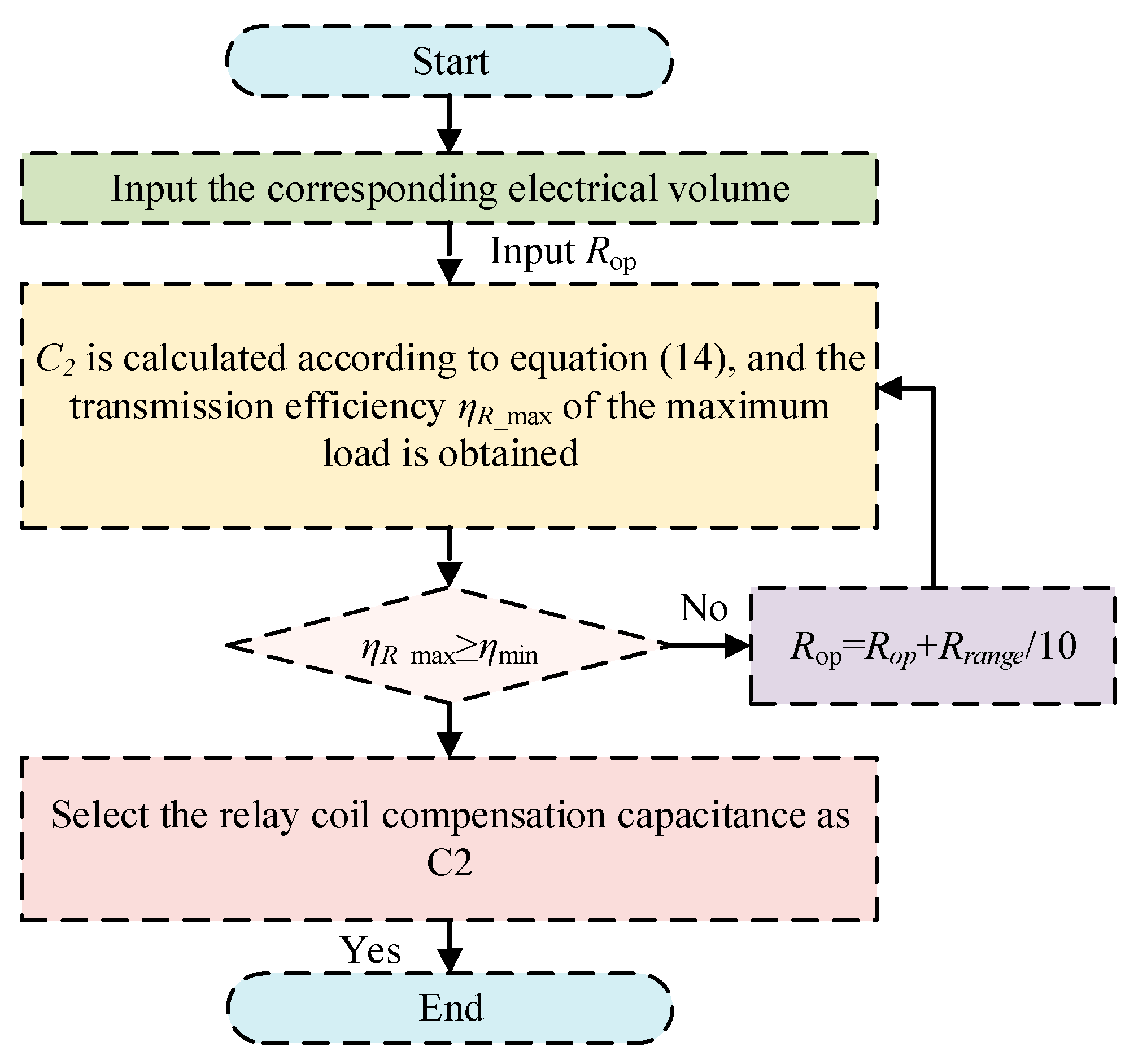
Through the relationship between inductance and capacitance, we can obtain Equation (14):
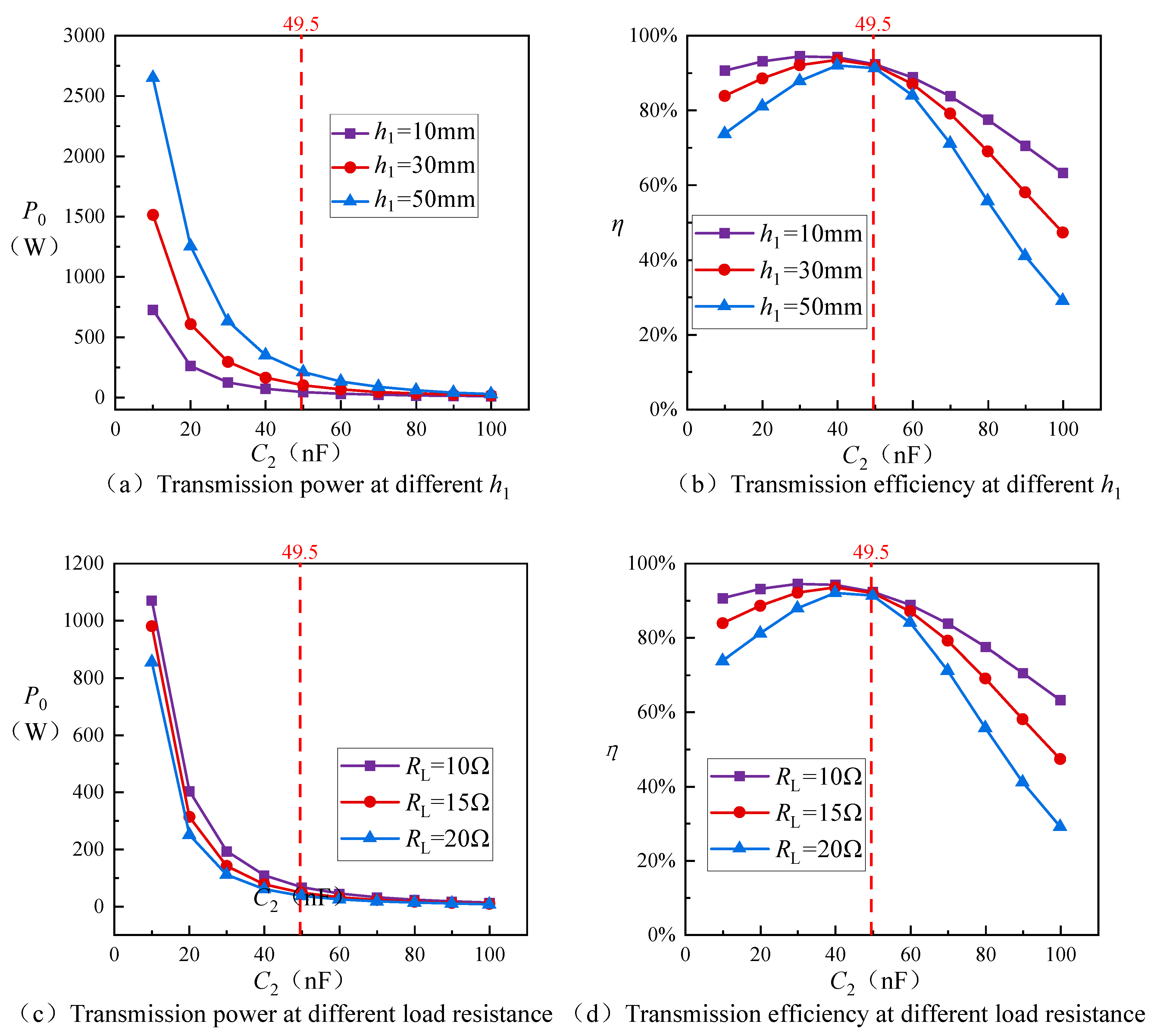
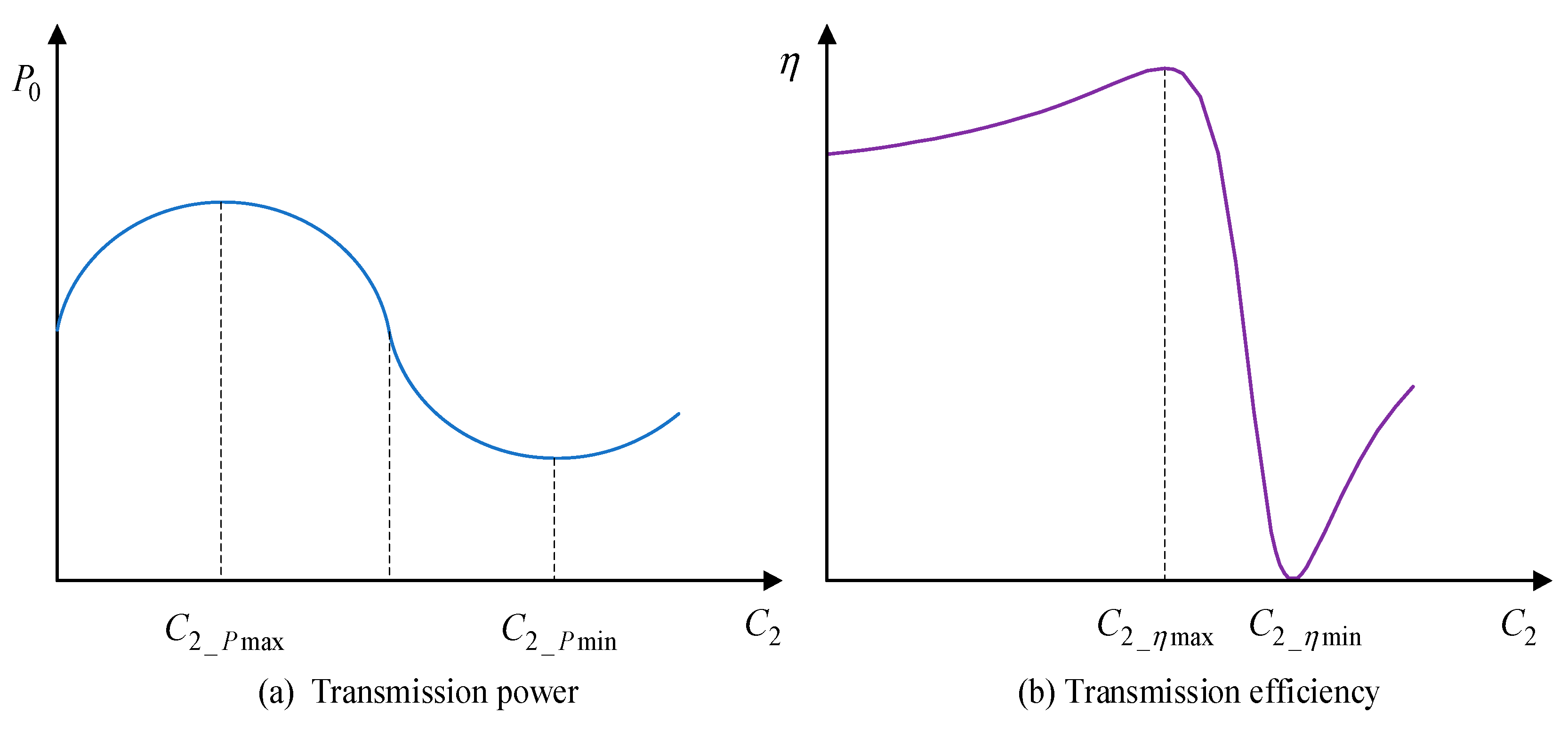
Figure 6 shows the increase and decrease characteristics of the output power and transmission efficiency of a three-coil wireless power transmission system with different capacitor compensations. The output power and transmission efficiency correspond to the two capacitors that make the maximum and minimum values, respectively. In practical applications, different capacitance values can be selected based on their characteristic curves.
3.2. Analysis of the Anti-Offset and Sensitivity of the System after Capacitor Optimization
In wireless power transmission systems, the offset of the coil position is a possible factor that can lead to a decrease in system performance. The offset of the coil position may be caused by manufacturing errors, equipment aging, mechanical vibration, and improper user operation, resulting in a reduced coupling effect between coils or alignment errors. This phenomenon is common in wireless power transmission systems, especially when resonant coils are used for power coupling in wireless power transmission systems. The offset of the coil position may have a negative impact on the transmission efficiency, transmission distance, and stability of the system. Through in-depth analysis of coil position offset in wireless power transmission systems, it will help to understand the impact of this offset on system performance and provide strong reference and guidance for designing more stable and efficient wireless power transmission systems. In this section, the system’s h1 = h2 = 30 mm, and the other parameters are consistent with the previous section. The compensation capacitor is set to the optimized value.
Sensitivity refers to the ability of a WPT to respond to changes in compensation capacitance and load resistance. The variation in compensating capacitance and load resistance will affect the resonant frequency and power transmission efficiency of WPT system. When the compensation capacitance is increased, the resonant frequency of the system will decrease, and the power transmission efficiency may decrease. On the contrary, when the compensation capacitance is reduced, the resonant frequency of the system will increase, and the power transmission efficiency may be improved. When the load resistance increases, the match between the load and the transmission line may become worse, and the power transmission efficiency may decrease. On the contrary, when the load resistance is reduced, the match between the load and the transmission line may become better, and the power transmission efficiency may be improved. Therefore, the sensitive system can sense the change of compensation capacitance and load resistance in time and take corresponding control measures to keep the performance of the system stable.
In WPT systems, the anti-offset and the sensitivity of system are related. A system with strong offset is better able to adapt to changes in the position of the device and therefore better able to maintain the sensitivity of the system. However, even if the system has strong offset, if its sensitivity is low, there may still be a problem of decreased power transmission efficiency when compensating for changes in capacitance and load resistance. Therefore, the system design and control strategy should take the anti-offset and sensitivity of the system into account to achieve stable power transmission.
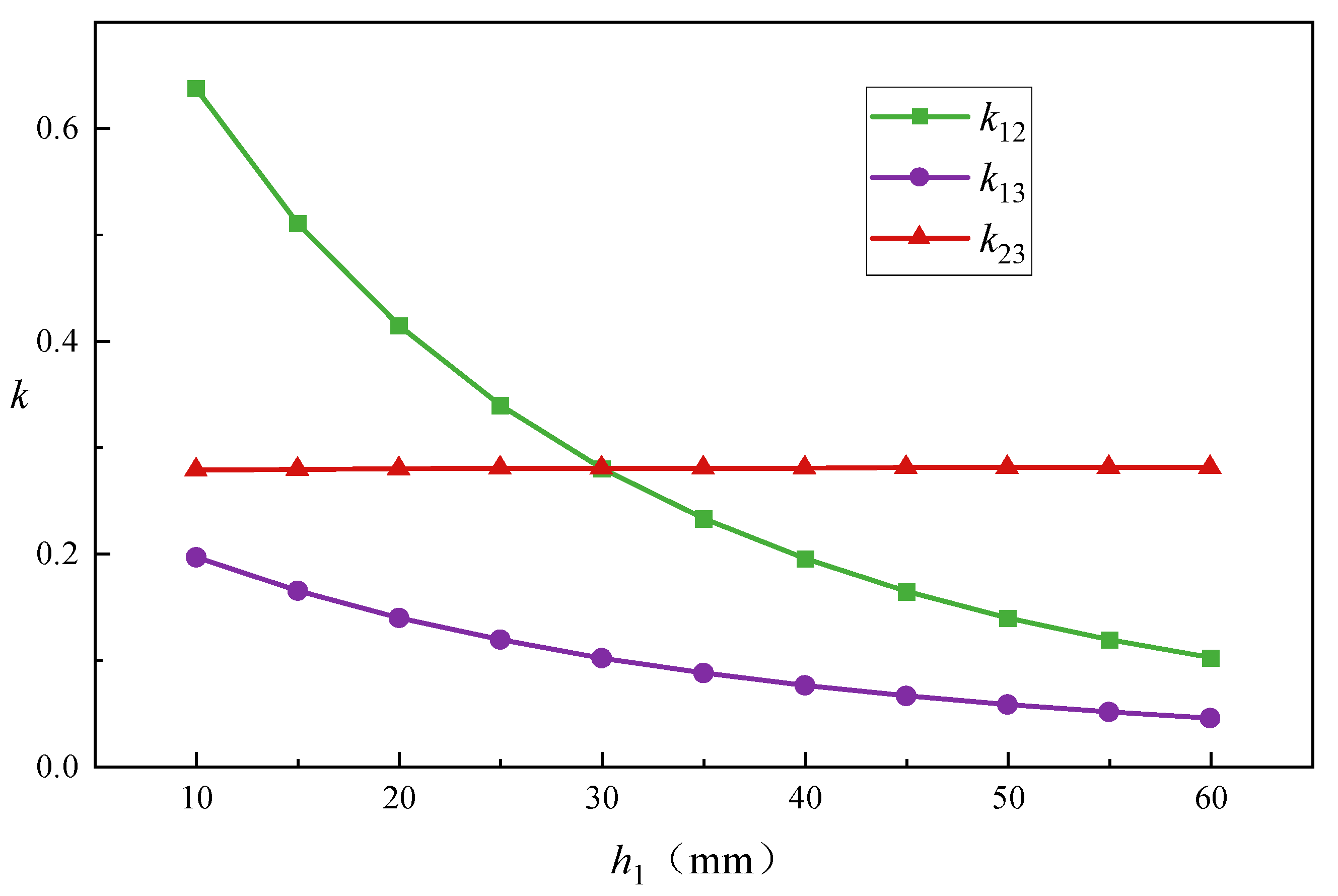
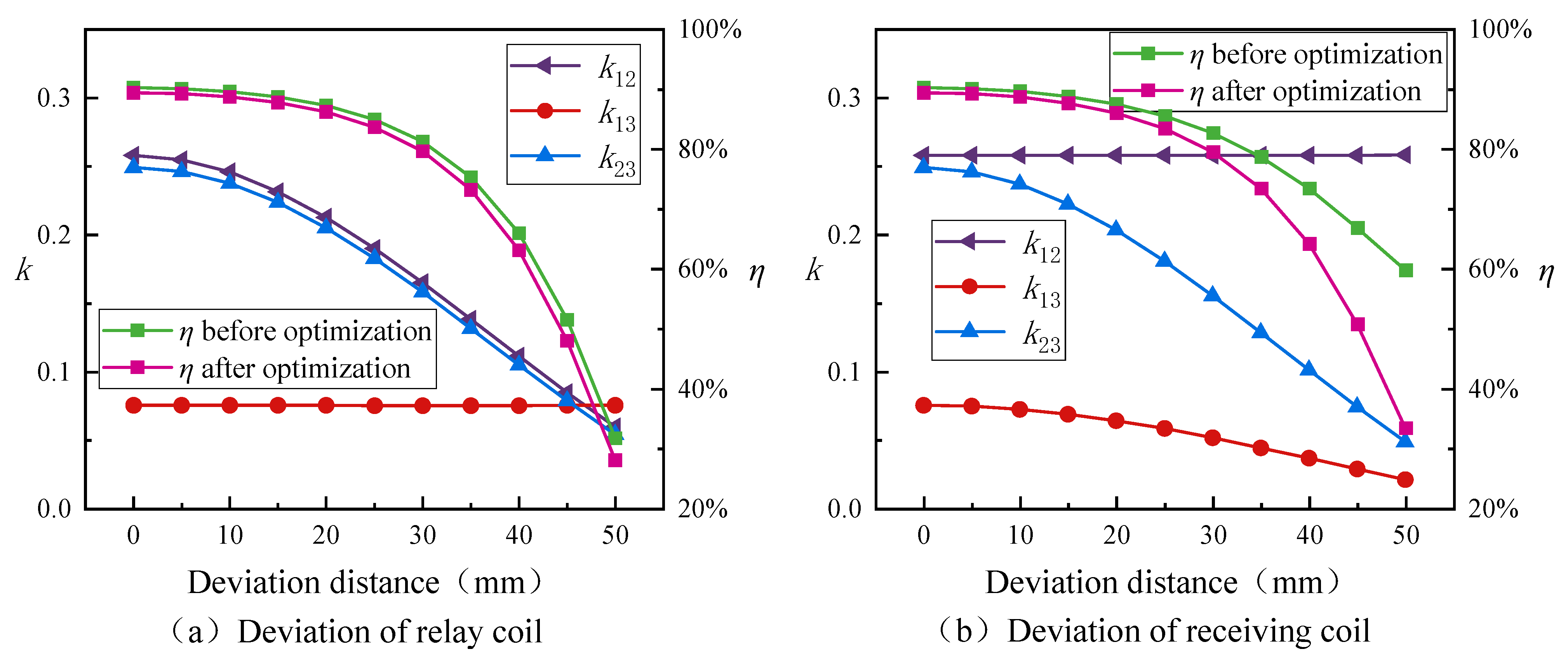
Figure 7 shows the change in coupling coefficient of the coaxial three-coil wireless power transmission system when the relay coil and receiver coil are offset, and the impact of coil offset on the transmission efficiency of the system before and after capacitor optimization. From
Figure 7a, it can be seen that the coupling coefficient of the system does not change much when the relay coil is offset within a range of 10 mm. However, when the offset distance is greater than 10 mm, the coupling coefficient of the system shows a significant decrease, and the downward trend of
k12 and
k23 is the same, with a decrease of 76.9%. Although the decrease is significant, it is also foreseeable because we have set both
h1 and
h2 to 30 mm, which is already a relatively large transmission distance for this system. Compared to the coupling coefficient, the decrease in efficiency starts with a significant decrease from an offset distance of 25 mm. Interestingly, the difference in system transmission efficiency before and after optimization also shows a significant change from a coaxial offset distance of 25 mm, ranging from 0.8% of 0 mm to 3.6% of 50 mm. In
Figure 7b, the changes in
k23 are basically the same as those in
Figure 7a, except that
k13 is less affected by the offset of the receiver coil. This is reflected in the efficiency aspect, which is that the optimized system transmission efficiency has a slower decline trend than when the relay coil is offset, and the decrease is not significant. On the contrary, although the decrease in system efficiency before optimization is not as significant as when the relay coil is offset, its sensitivity to coil offset is much greater than after optimization. This is reflected in the data. Before optimization, the transmission efficiency of the system decreased from 89.5% to 33.5%, with a decrease of 62.6%. After optimization, the transmission efficiency of the system decreased from 90.3% to 59.9%, with a decrease of 33.7%. The efficiency difference before and after optimization increased from 0.8% at the beginning to 26.4% at an offset distance of 50 mm.
The above analysis shows that the coaxial three-coil wireless power transmission system is more sensitive to the position offset of the relay coil, and the system after optimizing the capacitor has stronger anti-offset performance compared to the system before optimizing the capacitor, especially when the position of the receiver coil shifts.
3.3. Frequency Characteristics of the System after Capacitor Optimization
In wireless power transmission systems, frequency is to a large extent a key parameter that affects system characteristics, mainly reflected in voltage gain and input phase angle. In terms of voltage gain, since the DC voltage hardly changes during operation, a relatively stable output voltage is related to the safety of the charging process and battery life. In addition, the implementation of zero voltage switching can reduce the switching loss of the inverter, ensure safe operation, and the input impedance angle can directly reflect the zero-voltage switching area. Detailed description is in
Appendix C. According to Equation (17), the following Equations (15) and (16) can be obtained:
In the formula,
GV is the voltage gain and
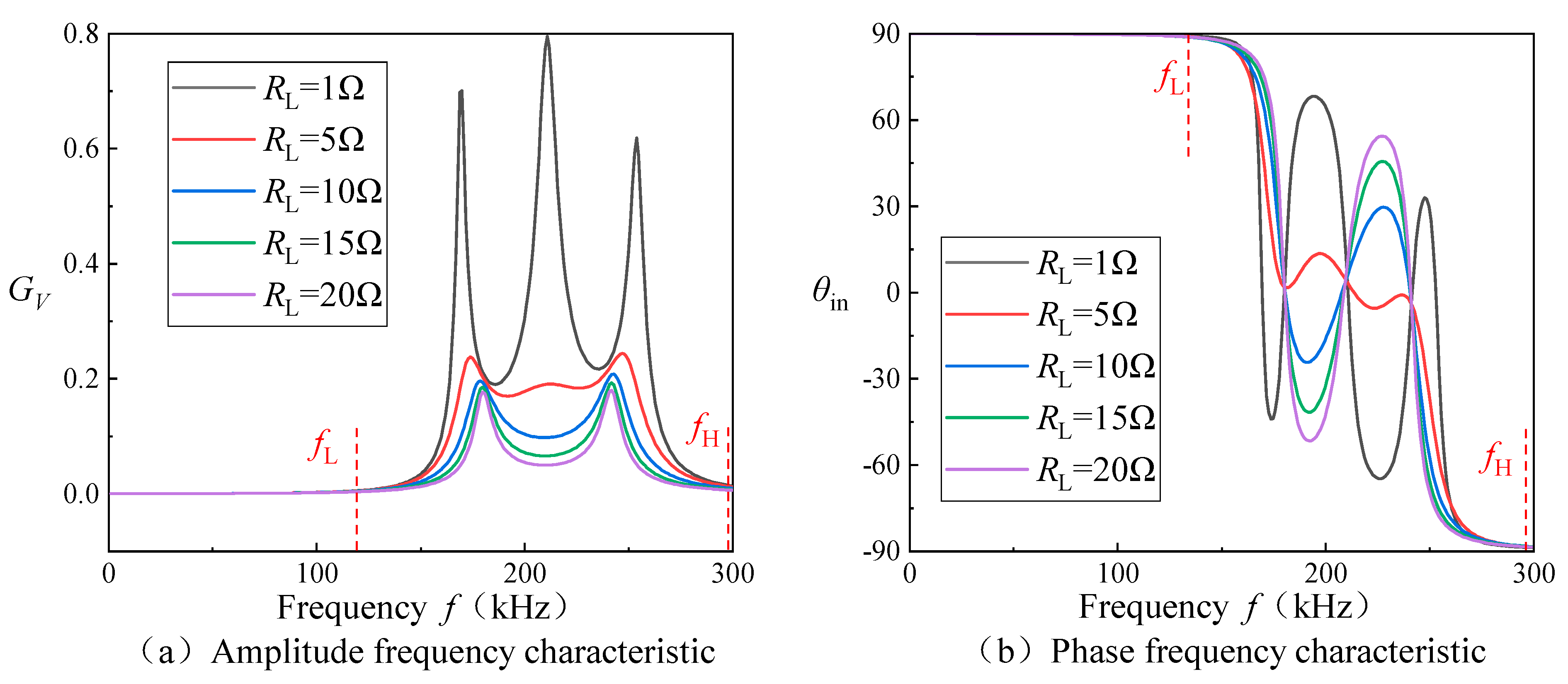
θin is the input impedance angle of the three-coil wireless power transmission system. According to Equations (15), (16) and (18), we can obtain the voltage gain and input impedance angle of the three-coil wireless power transmission system under different load conditions, as shown in
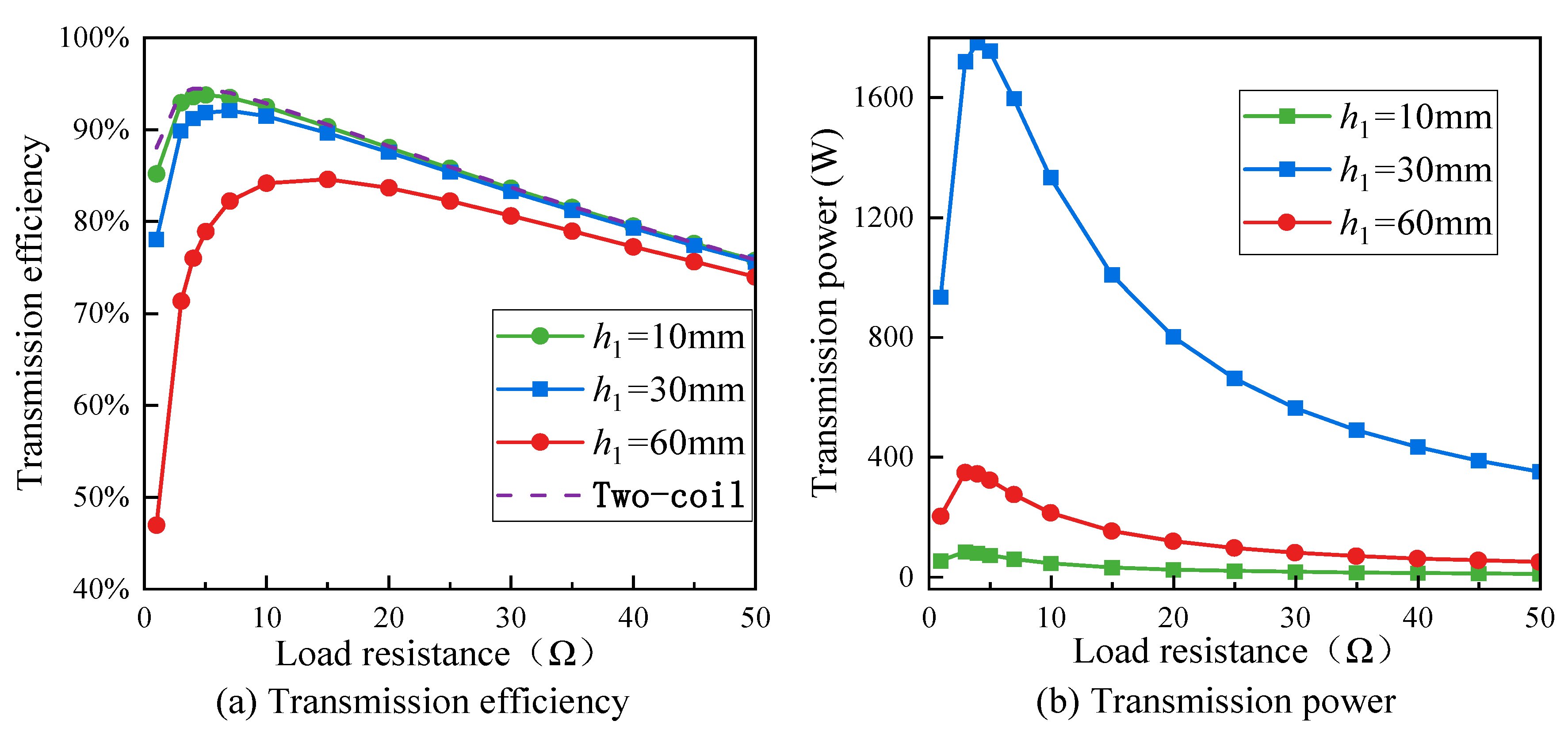
Figure 8.
According to the results shown in
Figure 8a, it can be seen that the wireless power transmission system with three coils will have three frequency bifurcation points when the load resistance
RL is small (load resistance
RL = 1 Ω), while the two-coil system only has two. The common point of both systems is that there are two additional
fL and
fH frequency points. When the system operates at a frequency
f <
fL or
f >
fH, although the load resistance
RL changes greatly, the voltage gain
GV remains almost unchanged. However, unlike the two-coil system, even after the load resistance
RL increases, the three-coil system still has two frequency bifurcation points, and a concave curve appears near the second bifurcation point when the load resistance
RL is low. In addition, for the input impedance angle
θin in
Figure 8b, when the resistance value is low,
θin is the value of fluctuations near the frequency bifurcation point. As the resistance increases, a concave parabolic curve appears near the first frequency bifurcation point, and a convex parabolic curve appears near the second frequency bifurcation point. In a three-coil wireless power transmission system, the distance and position relationship between coils has a significant impact on transmission efficiency and power transmission efficiency. Through analyzing the
S-parameter, the optimal location and distance for the transmission efficiency and power transmission efficiency between coils can be identified, and the size and shape of the coils can be optimized during the design phase to achieve the best transmission efficiency.
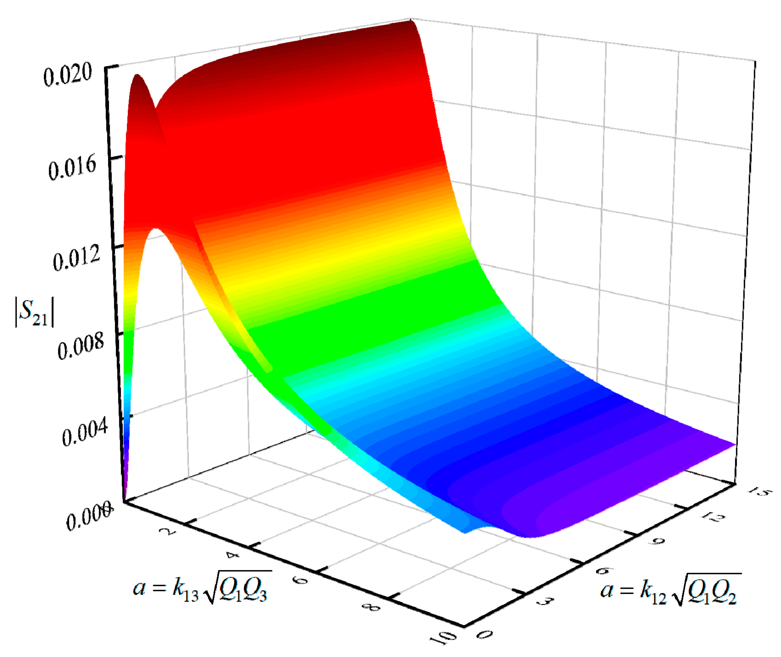
The S-parameter refers to the scattering parameter, which is a parameter used to describe the transmission and reflection of signals in a circuit. It describes the relationship between the input and output, as well as the signal transmission and reflection between different locations in the circuit, usually using the S-parameter to evaluate the performance of the circuit, optimize the design of the circuit, perform circuit analysis, etc. The S-parameter plays a very important role in the two-coil radio energy transmission system. Because the radio energy transmission system is completed by the radiation and reception of electromagnetic waves, the transmission and reflection of electromagnetic waves must be fully understood and analyzed. The S-parameter can be used to describe the electromagnetic wave transmission efficiency and power transmission efficiency between coils, helping designers optimize system performance. In addition, the S-parameter can also be used to evaluate the stability and anti-interference ability of the system. Through analyzing S-parameters, we can identify the instability and interference sources that may exist in the system and take corresponding measures to solve these problems. According to Equations (17) and (21), we can obtain the S-parameters of the three-coil system:
where
Q is the quality factor of the circuit where the corresponding inductance is located, where
RS and load resistance
RL are both set to 50 Ω, which is the general value of the power impedance in the high-frequency circuit. At the same time, we set
a =
b, so that the three-coil wireless power transmission system is a symmetrical system, which is also the choice of many researchers. The relationship between the amplitude of
S21 in the three-coil wireless power transmission system and
a and
c is shown in
Figure 9. From
Figure 9, it can be seen that there are two peaks in the system, and between the two peaks,
S21 shows a concave part. When
a and
c are greater than a certain value,
S21 shows a decreasing trend with the increase in
a and
c.
5. Simulation Analysis
In order to verify the rationality of the system design, Simulink software was used to build a circuit of a three-coil wireless power transmission system and conduct circuit simulation analysis. This can help optimize circuit performance, accelerate the design process, reduce design costs and improve circuit reliability. The simulation setting is shown in
Figure 13.
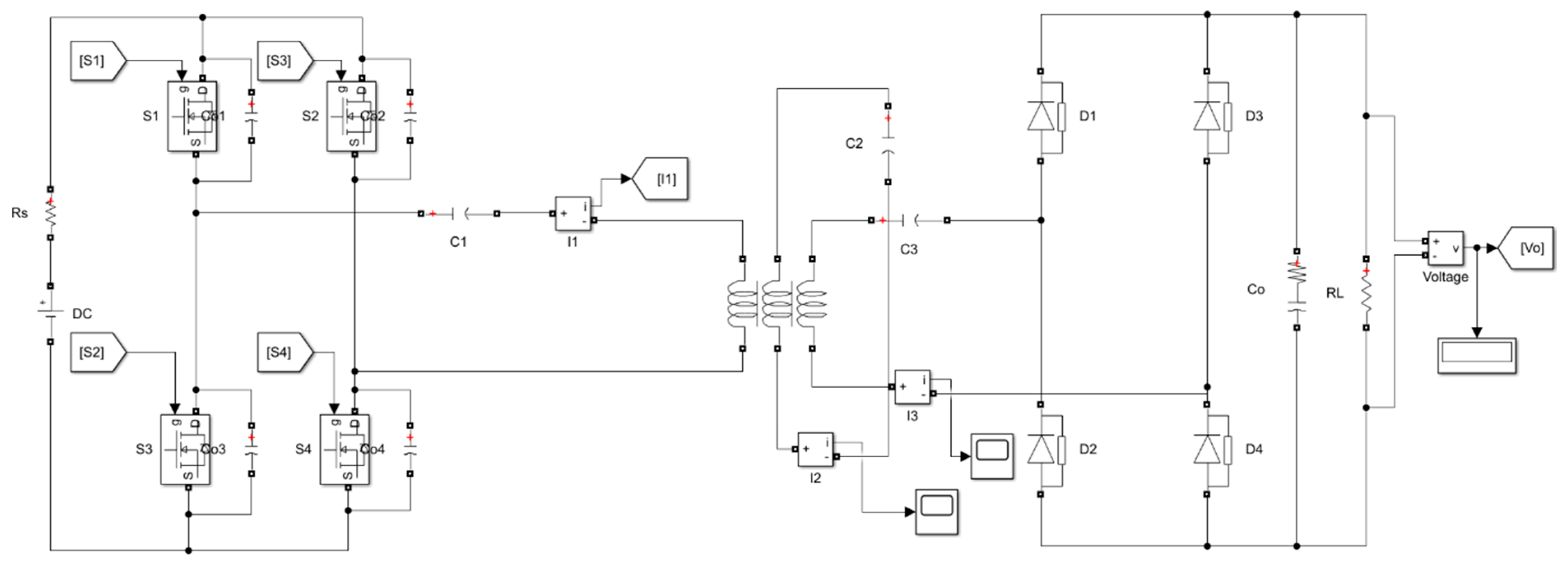
As shown in
Figure 14, the Simulink simulation circuit diagram of a magnetic coupling wireless power transmission system based on a relay coil is shown.
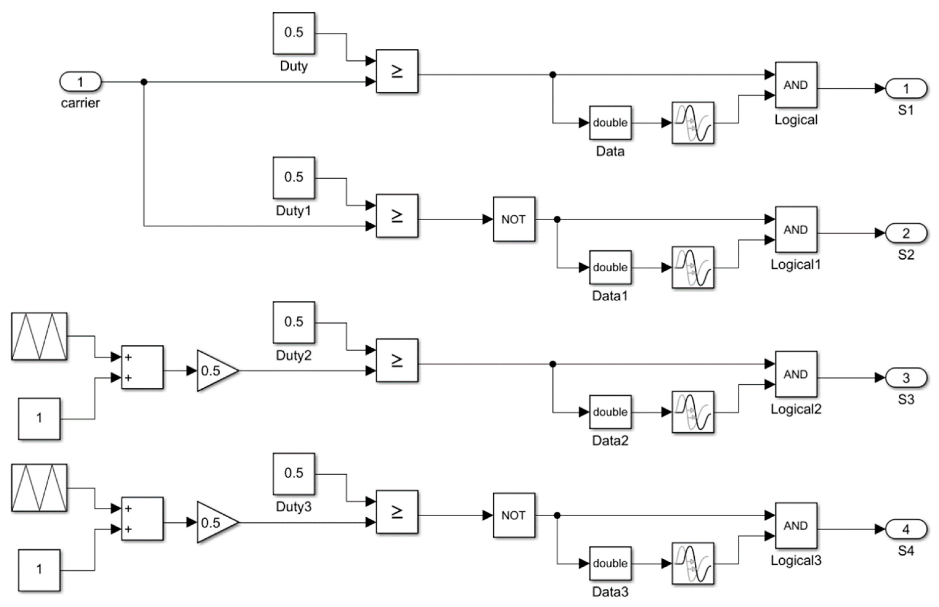
The four power switches S
1~S
4 form a full bridge inverter circuit, and the driving signal of the full bridge inverter circuit is controlled in
Figure 15. The transmit coil
L1 and capacitor
C1 form the transmit end of the system, the relay coil
L2 and capacitor
C2 form the relay coil compensation network, the transmit coil
L3 and capacitor
C3 form the receiving end, and
D1~
D4 form the rectifying circuit. Rectify the AC power obtained from the transmit coil into DC power to supply the load resistance
RL.
In order to simulate the transmission between coils in the Simulink simulation, we used a coupled inductance model that considers the self-inductance and mutual inductance between coils, as well as the parasitic resistance of the inductance itself. In order to facilitate circuit simulation analysis of transmission situations at different distances, we first established a three-coil coupled transmission model using ANSYS Maxwell electromagnetic simulation software.
Table 3 shows the simulation results of the coupling coefficient between coils when the transmission distance
h1 between the transmit coil and the relay coil changes from 10 mm to 60 mm.
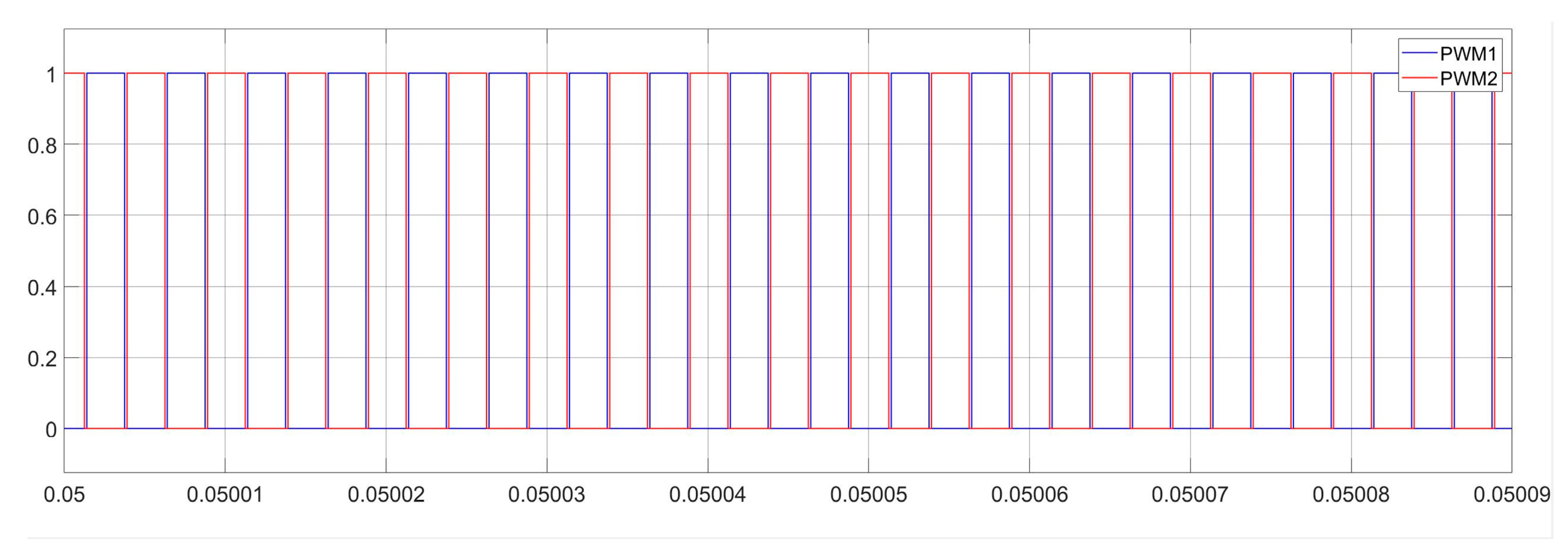
Firstly, in order to ensure the rationality of system simulation analysis, it is necessary to analyze and verify the working status of each key point in the circuit.
Figure 15 shows two pulse drive signals, with PWM
1 and PWM
2 controlling the conduction states of S
1, S
3, S
2 and S
4, respectively.
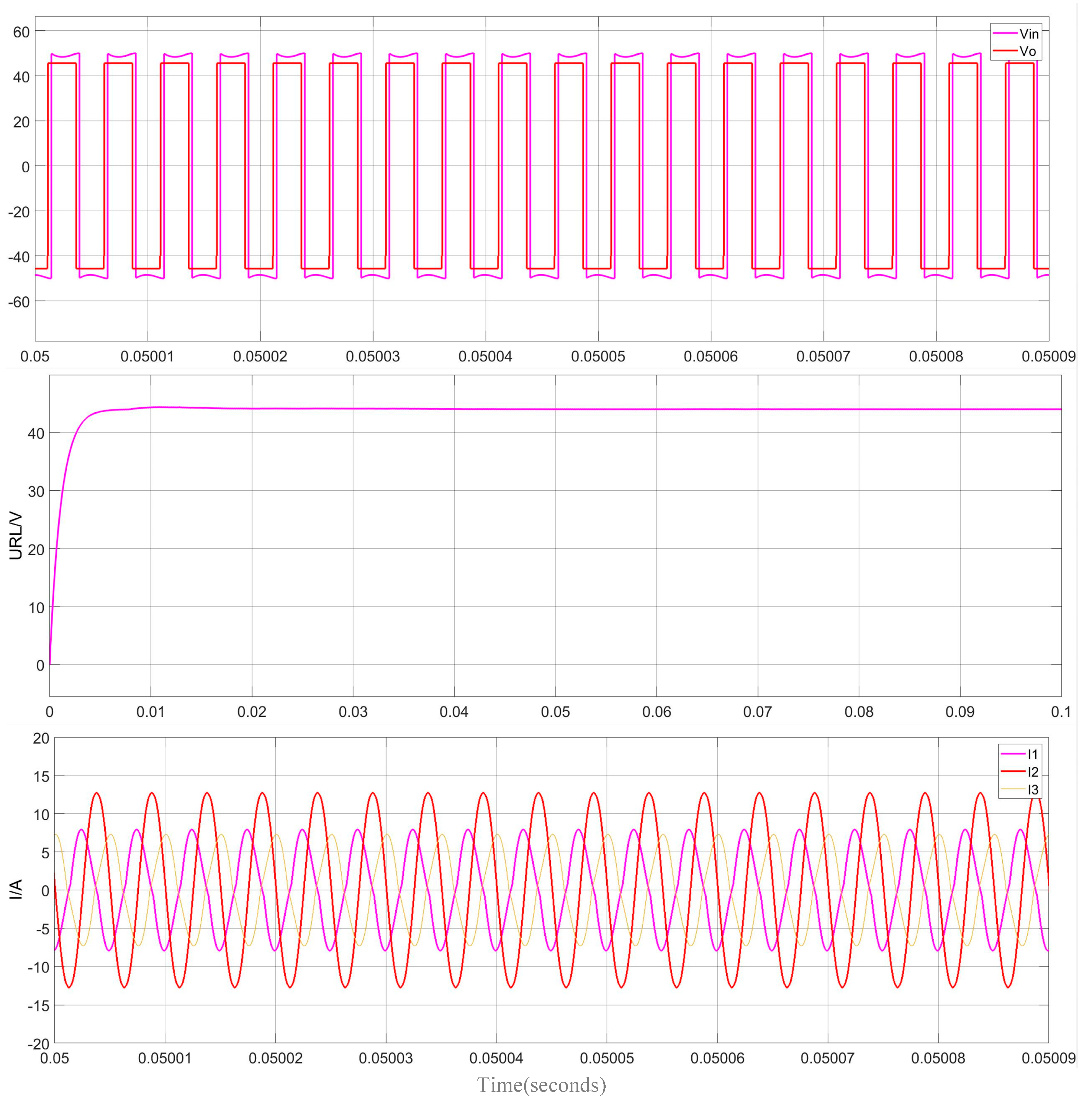
Figure 16 shows the waveform of key points in the system’s power transmission process. The coil coupling model parameters are based on Maxwell simulation results at
h1 = 30 mm.
Vin is the output voltage waveform of the full bridge inverter circuit,
Vo is the output voltage waveform of the receiver coil compensation network,
URL is the voltage waveform of both ends of the load, and
I1,
I2 and
I3 are the current waveforms of the transmit coil, relay coil and receiver coil, respectively. The simulation results show that the waveforms of each key point are consistent with the theoretical results analyzed above, thus verifying the rationality of this circuit simulation model.
In the simulation, the circuits of the transmission and receiver coils are adjusted to the resonant frequency, and the compensation capacitor of the relay coil is manually changed. Each compensation capacitor’s output voltage is simulated, and the transmission efficiency under the compensation capacitor is calculated, which is shown in
Figure 16.
In
Figure 16, the simulated tuning capacitor with the maximum transmission efficiency is 44.4 nF, which is 0.4 nF higher than its theoretical value of 44 nF, and the transmission efficiency is 3% higher than the highest theoretical value. After optimizing the compensation capacitance, the efficiency difference increases from 0.8% at the beginning to 26.4% at a 50 mm offset distance, and the system reduces current by 86.9%, increases system efficiency by 10% and suppresses electromagnetic field (EMF) leakage by 18 dB. Meanwhile, the capacitor optimization further improves transmission efficiency.
6. Discussion
In order to design and optimize the compensation capacitor of the relay coil in the three-coil WPT system, the influence of cross inductance and relay coil position on the system are respectively studied in this paper. Based on this, the compensation capacitance of the relay coil is changed.
It is found that the maximum transmission power and the transmission power of relay coil are not the resonant capacitance, but the maximum transmission power and the transmission power are obtained when the resonant capacitance is smaller. Then, based on the above analysis results, a relay coil compensation capacitance model to realize the optimal transmission power and transmission efficiency is proposed.
Then, the anti-offset performance and frequency characteristics of the system after capacitor optimization are analyzed. It is found that the system after capacitor optimization has stronger anti-offset performance than the system before capacitor optimization, especially when the position of the receiver coil is offset. In addition, in order to solve the problem of resistance change of battery load and mutual inductance change caused by coil position change, a design method of relay coil compensation capacitor based on dynamic load and a variable compensation capacitor circuit are proposed, respectively.
However, there are a few potential drawbacks or disadvantages of the proposed approach.
Firstly, the compensation capacitance optimization of the relay coil of the three-coil WPT system proposed in this paper is only applicable to the three-coil WPT system. For the case of multiple devices charging at the same time or multiple devices supplying power at the same time, how to design effectively needs to be further studied.
Secondly, the optimization method proposed in this paper does not consider the parameter design of the transmission coil and receiver coil in the optimization process, and more variables can be added in future work.
7. Conclusions
Wireless power transmission (WPT) technology, as an innovative technology, has gradually become a research focus in recent years because it eliminates the limitation of physical connection and improves convenience. In the current three-coil WPT system, the common power repeater is composed of a coupling coil and a compensation capacitor in series, and its tuning condition will affect the power transmission ability of the WPT system. However, the exact impact of the compensation capacitors is not clear, which has led to the design of power repeaters based on empirical or trial-and-error methods. The relay coil is placed in coplanar and coaxial positions, and the coplanar placement of the relay coil can help increase the self-inductance of the transmission coil and the mutual inductance between the transmission coil and the receiver coil.
In order to solve the above problems, this paper mainly studies the design and optimization of the compensation capacitor value of relay coil in three-coil WPT system. Through theoretical derivation and experimental verification, the following conclusions can be obtained:
(1) Through analyzing the influence of mutual inductance and relay coil position on common coaxial strongly coupled three-coil WPT system, the compensation capacitor value of the relay coil in the three-coil WPT system is optimized. It is found that, unlike two-coil WPT systems, the maximum transmission power and transmission efficiency of three-coil WPT systems are obtained when the compensation capacitor is less than the resonant capacitor, but not equal to the resonant capacitor.
(2) On the basis of the above analysis results, the optimum compensation capacitor value of the relay coil to achieve the maximum transmission power and transmission efficiency in the three-coil WPT system is derived, and a method for designing the compensation capacitor value of the relay coil based on dynamic load is proposed. Then, the anti-migration performance and frequency characteristics of the optimized capacitors are studied.
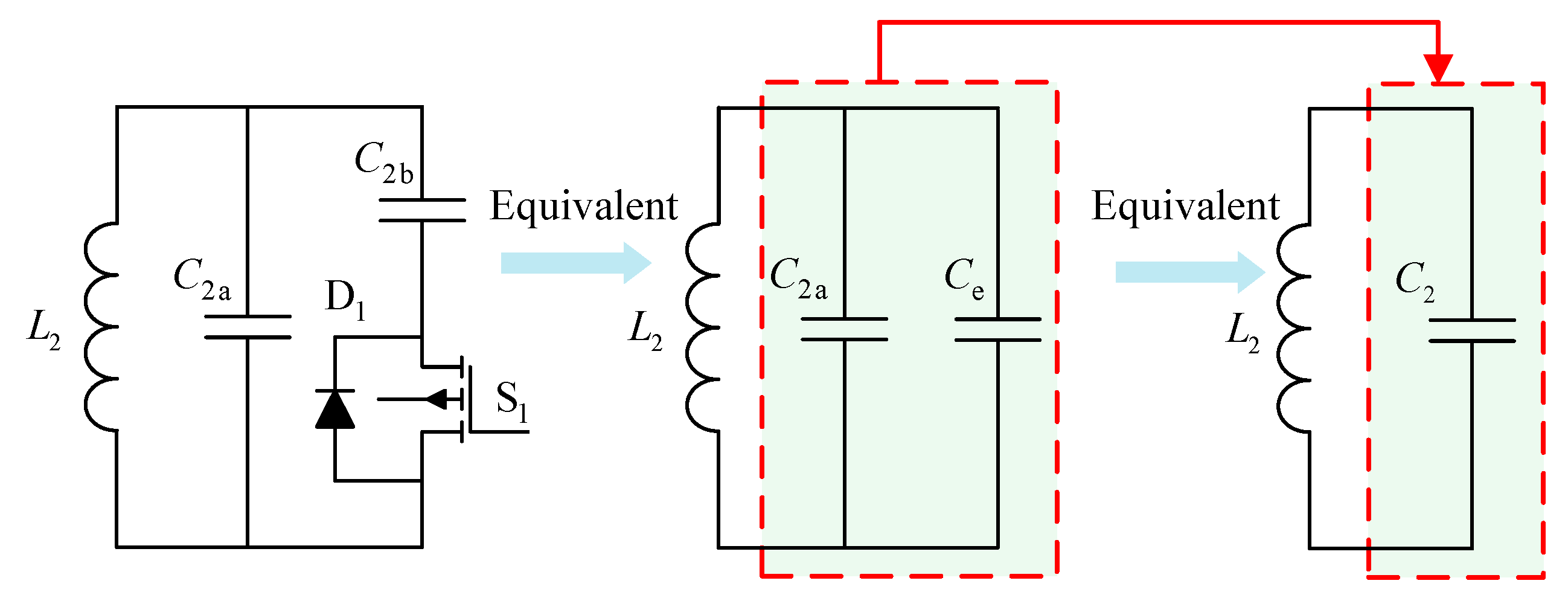
(3) A variable compensation capacitor circuit is proposed to solve the problem that the coil displacement often occurs in the operation of the three-coil WPT system, which leads to the change of system parameters and the change in the optimal compensation capacitor of the system.


 and
and 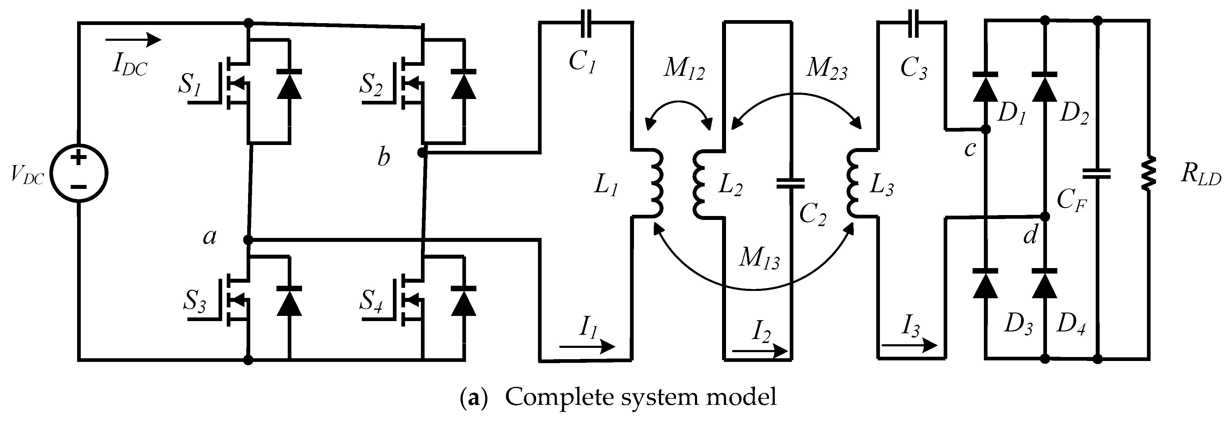
