
Investigation of Precast Reinforced Concrete Structures during the 6 February 2023 Türkiye Earthquakes


Abstract
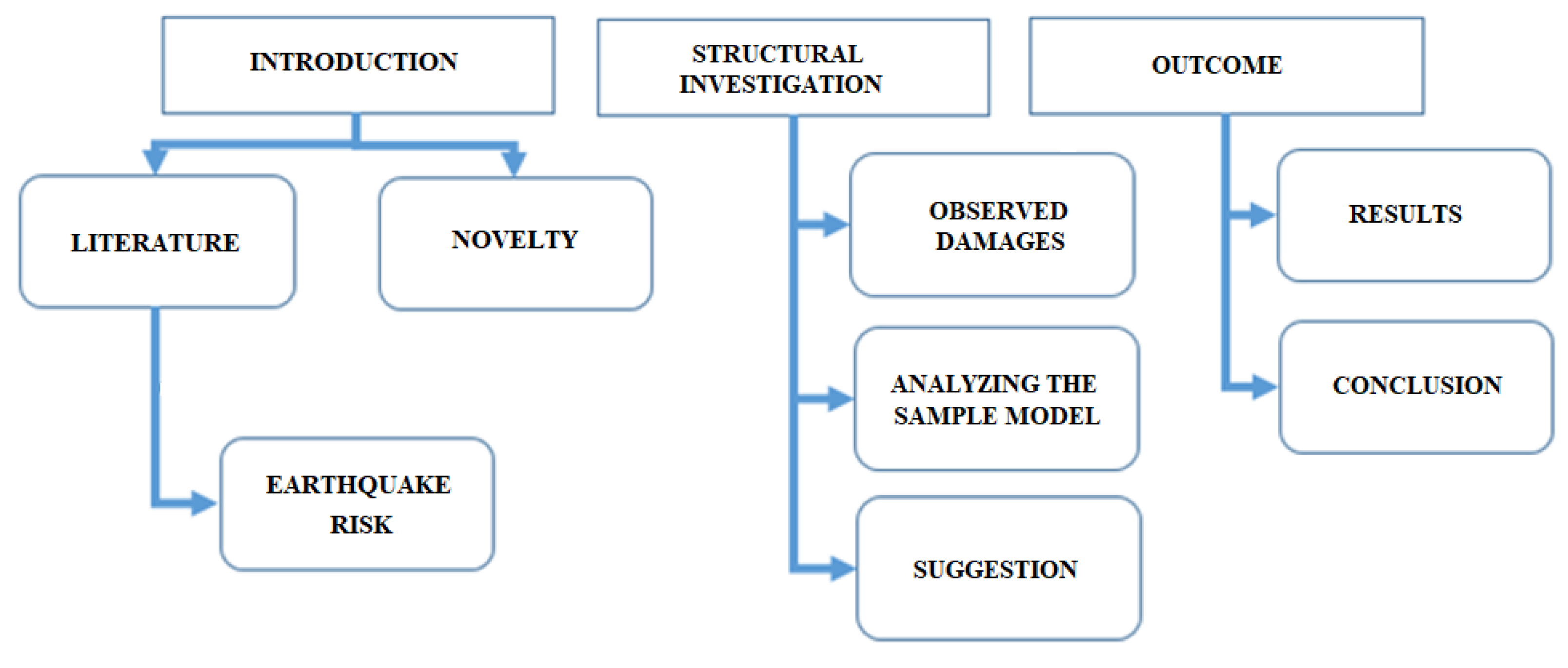
:1. Introduction
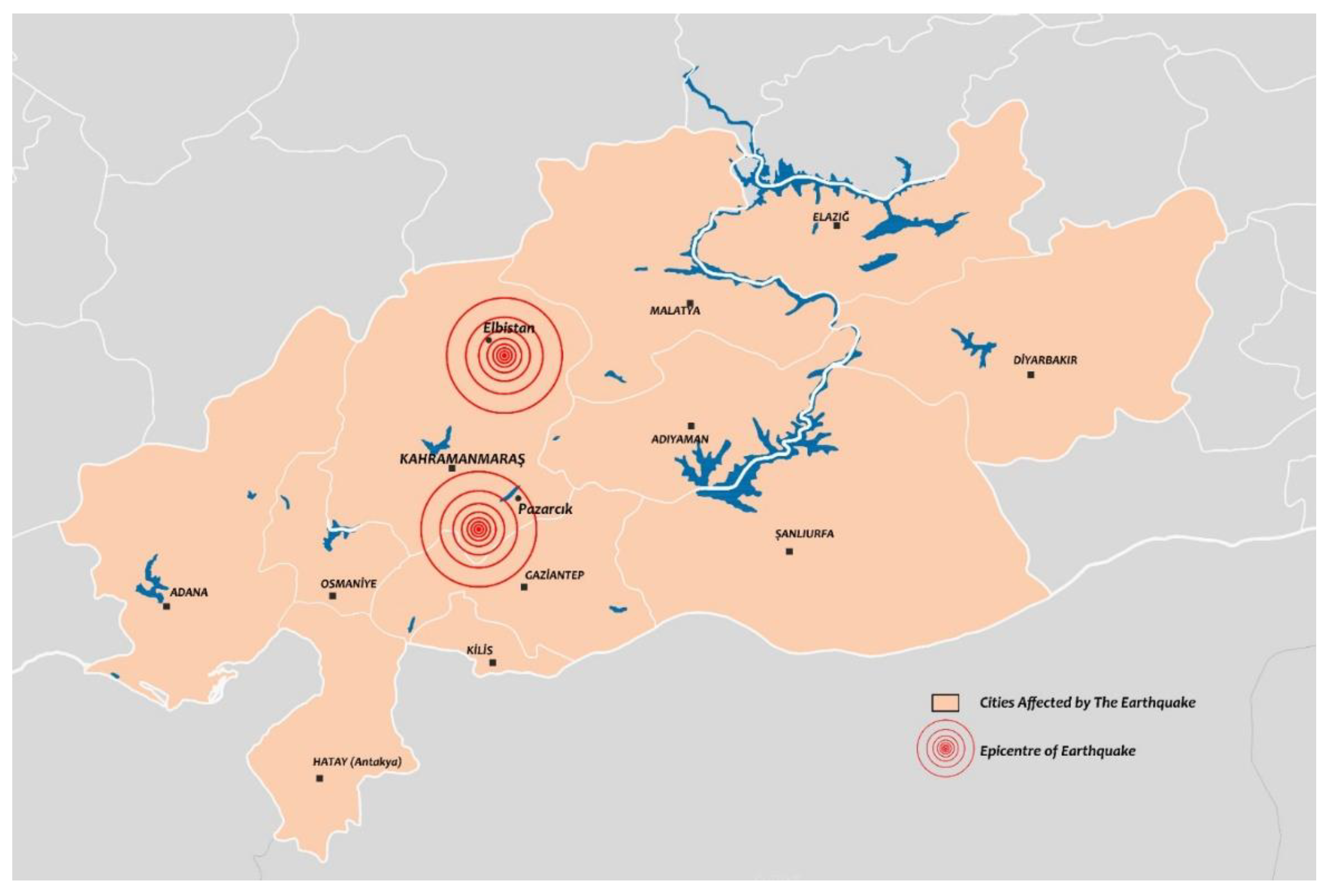
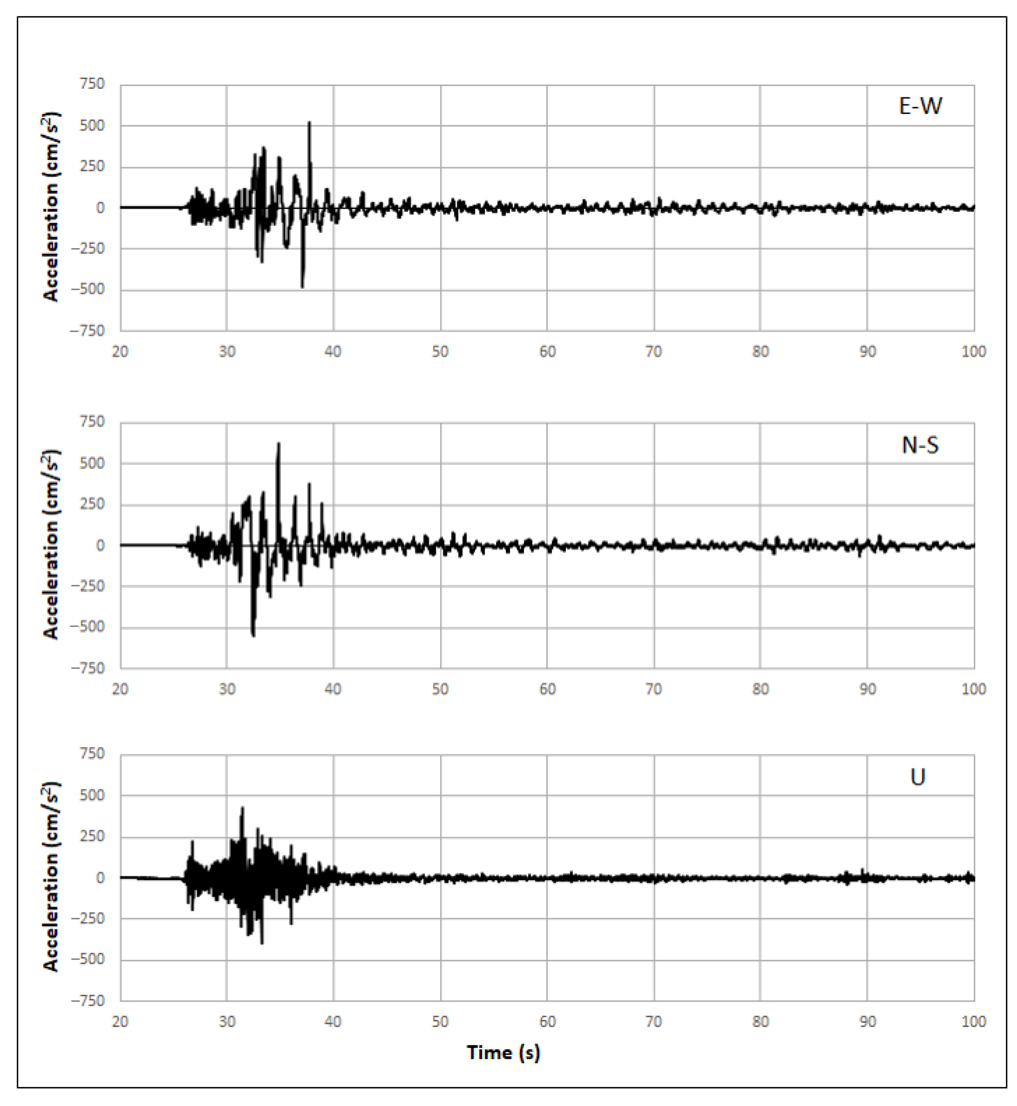
2. Kahramanmaraş Earthquakes
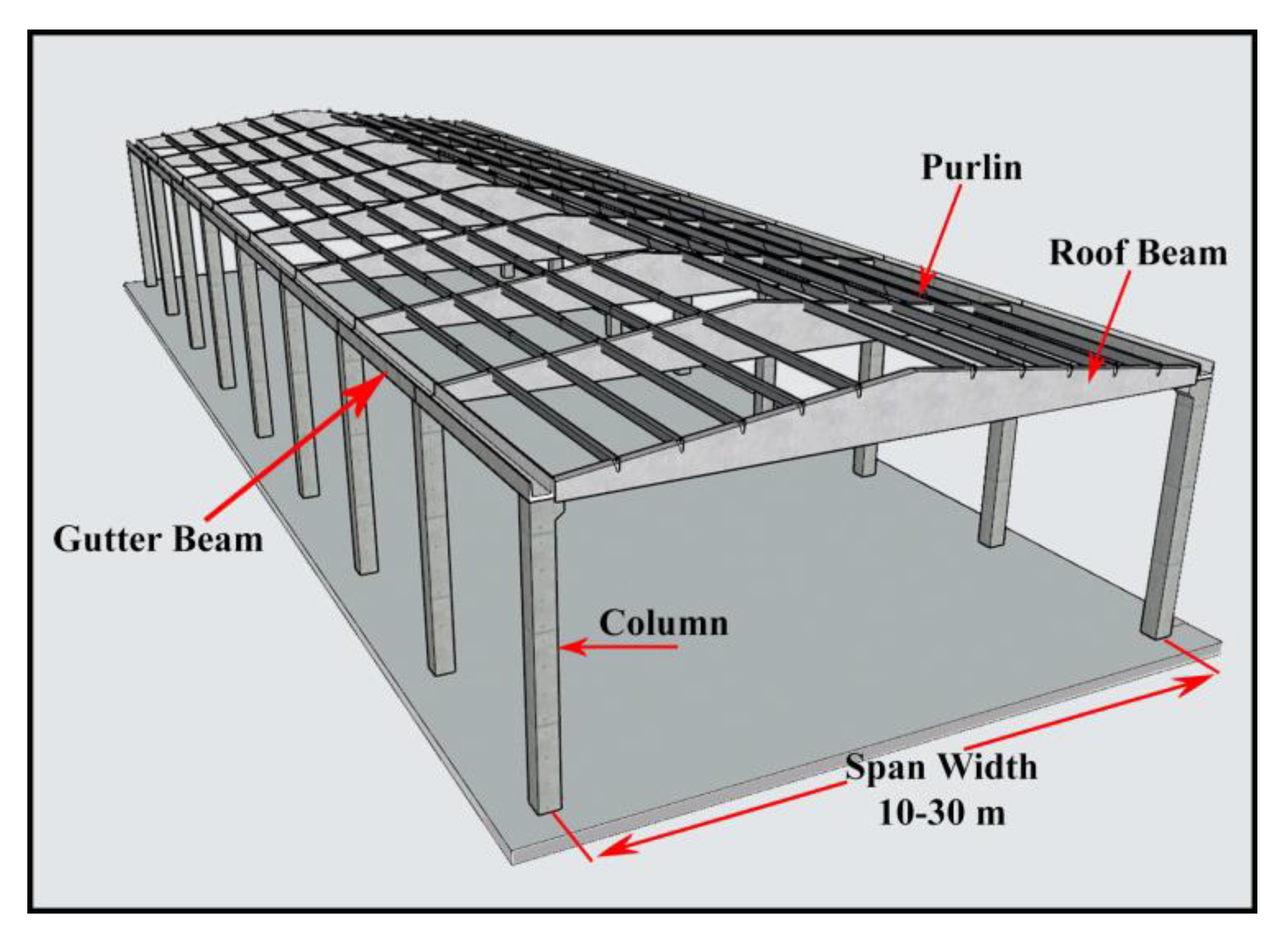
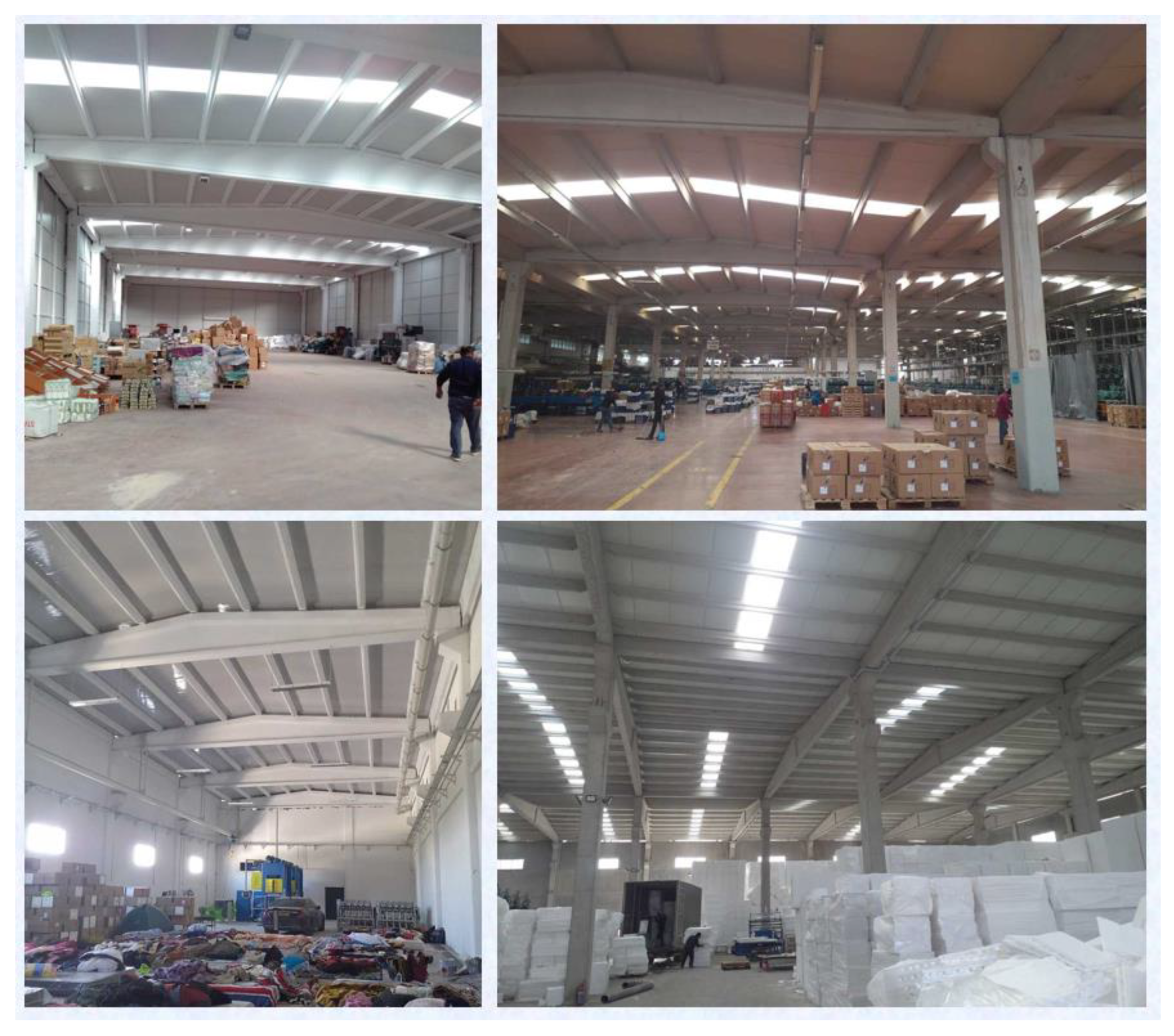
3. Description of Precast Buildings in the Region
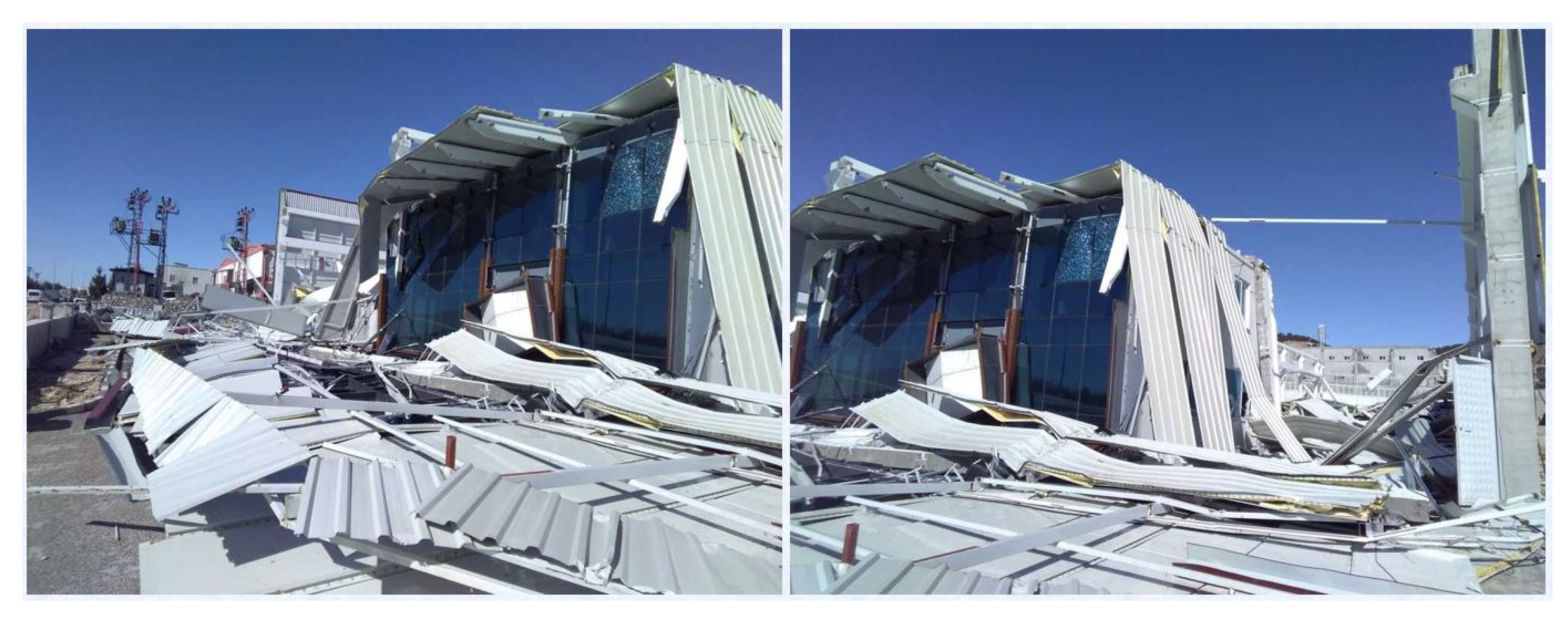
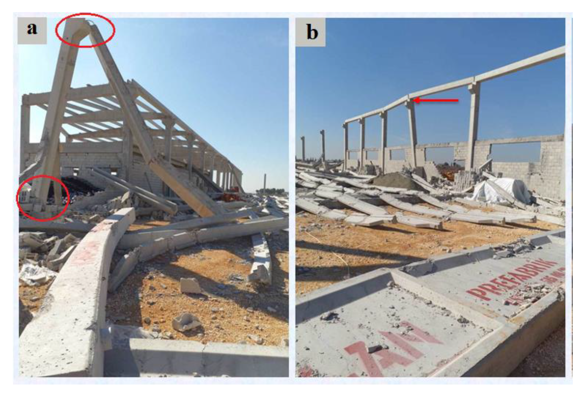
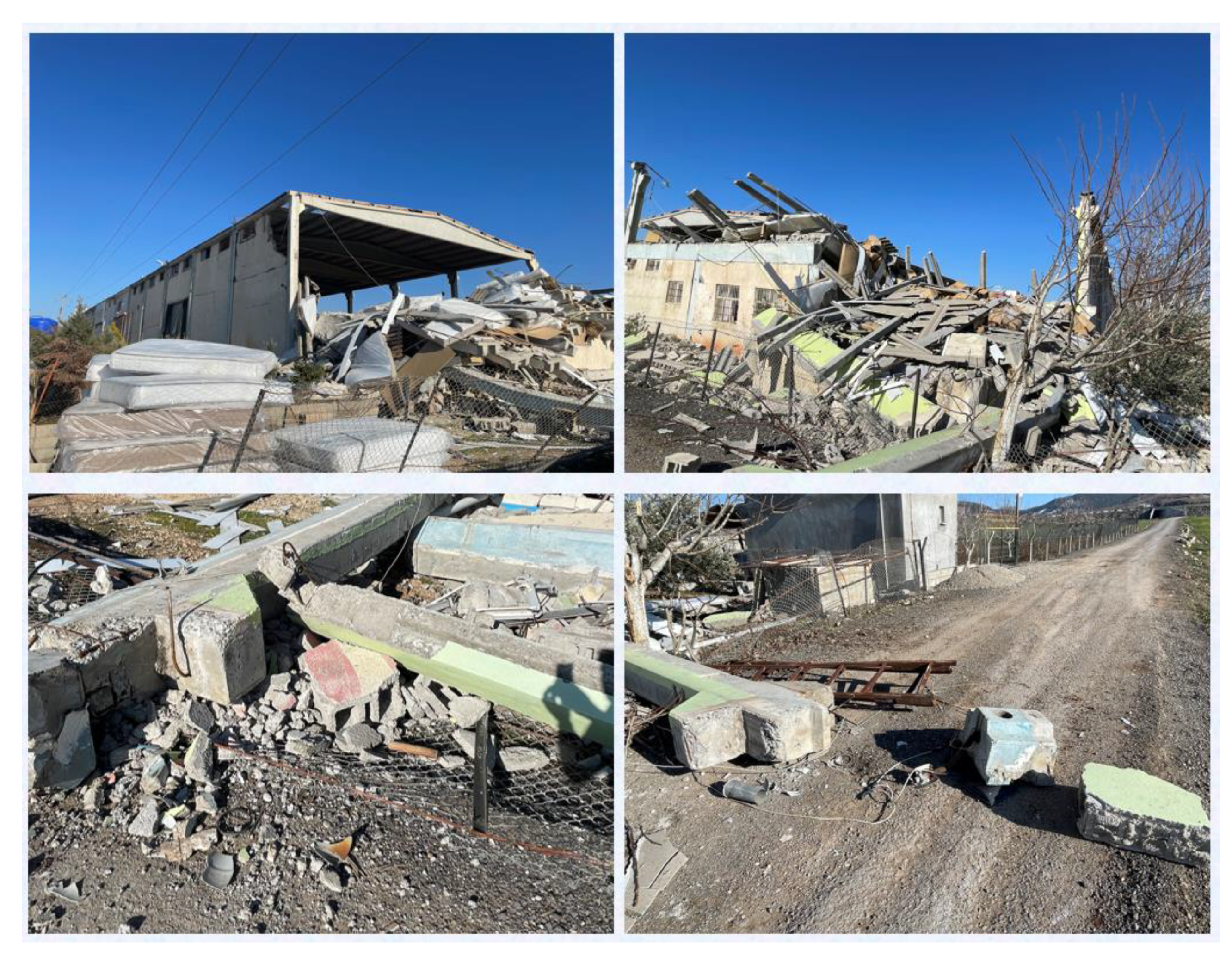
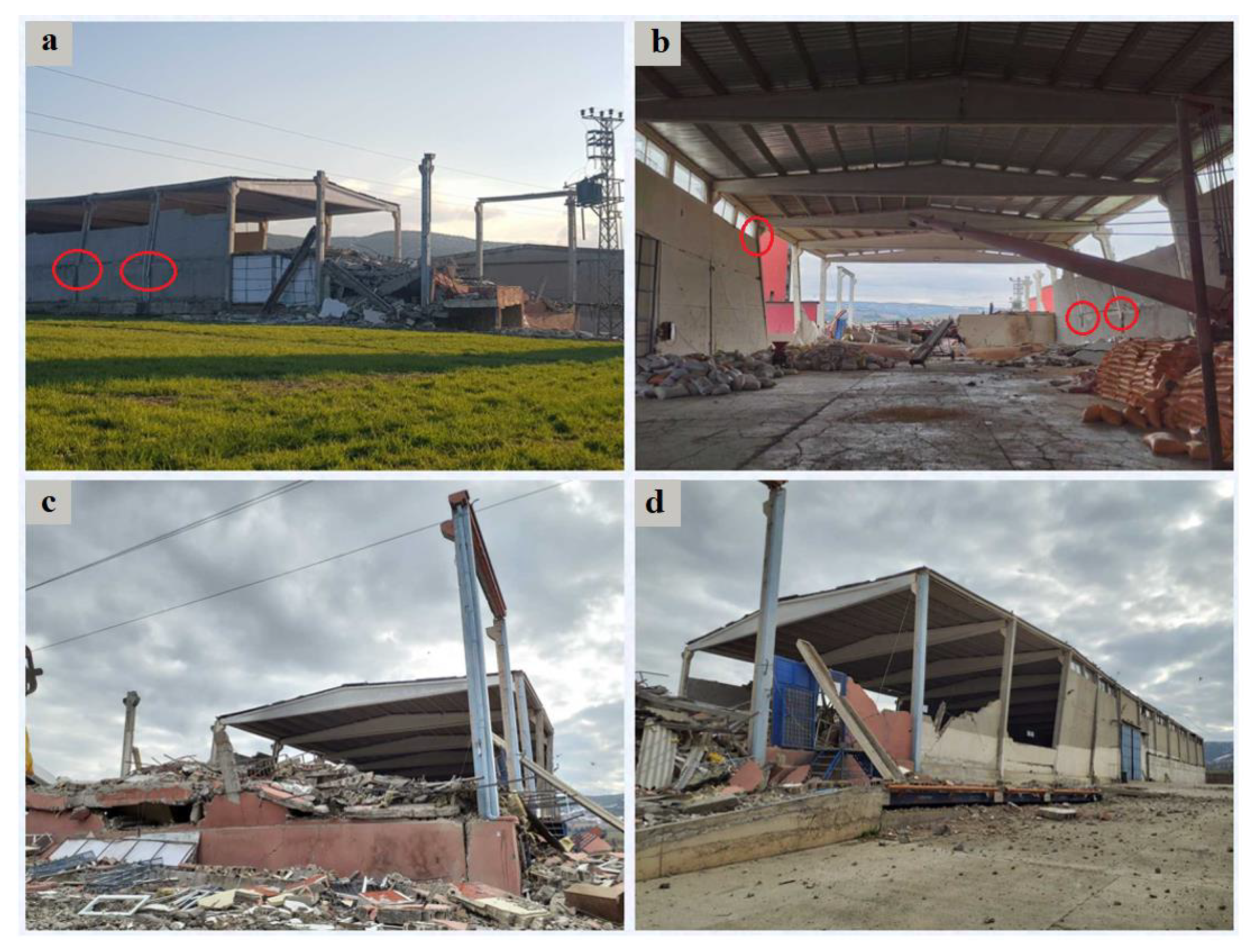
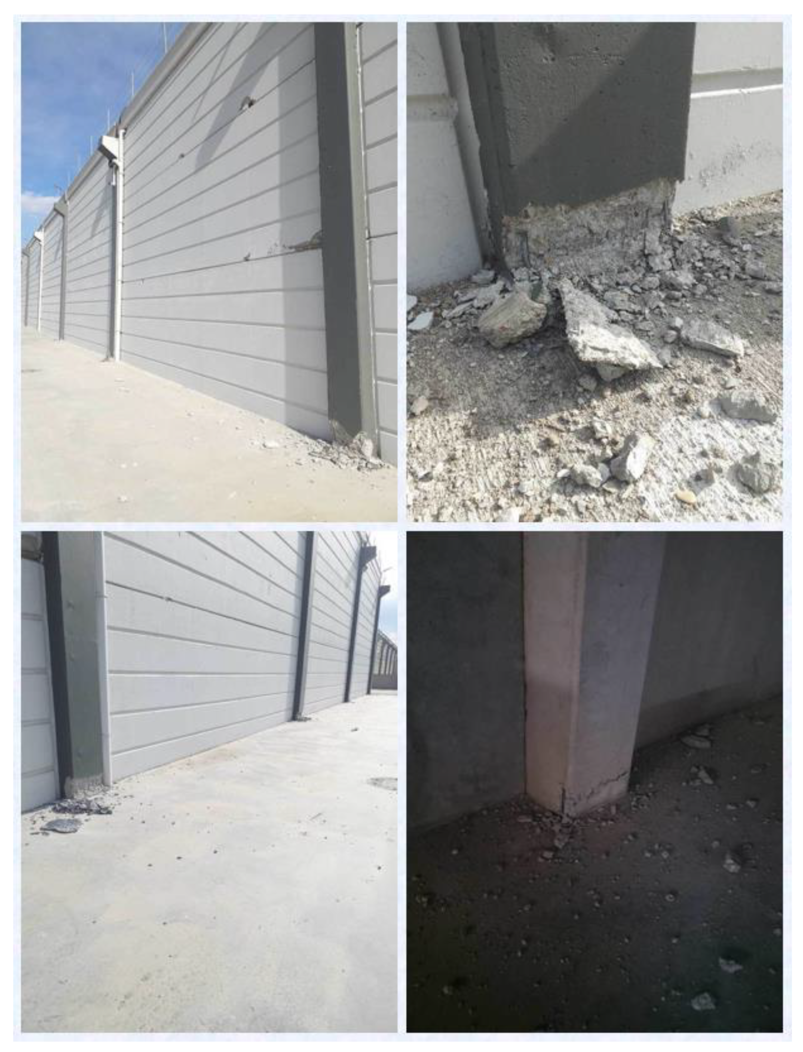
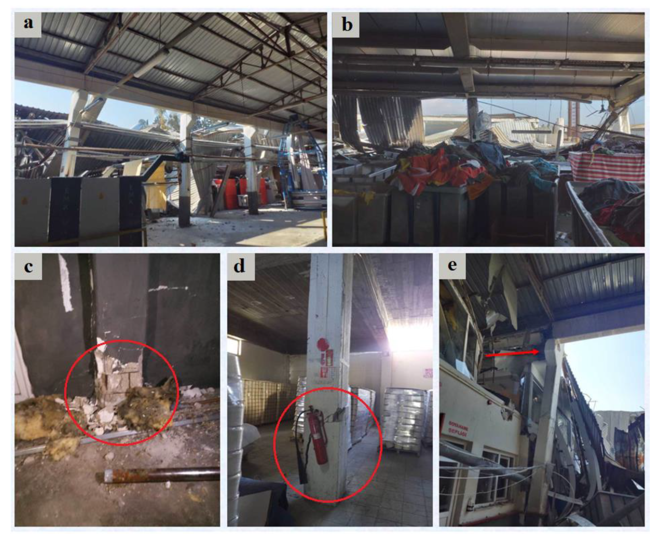
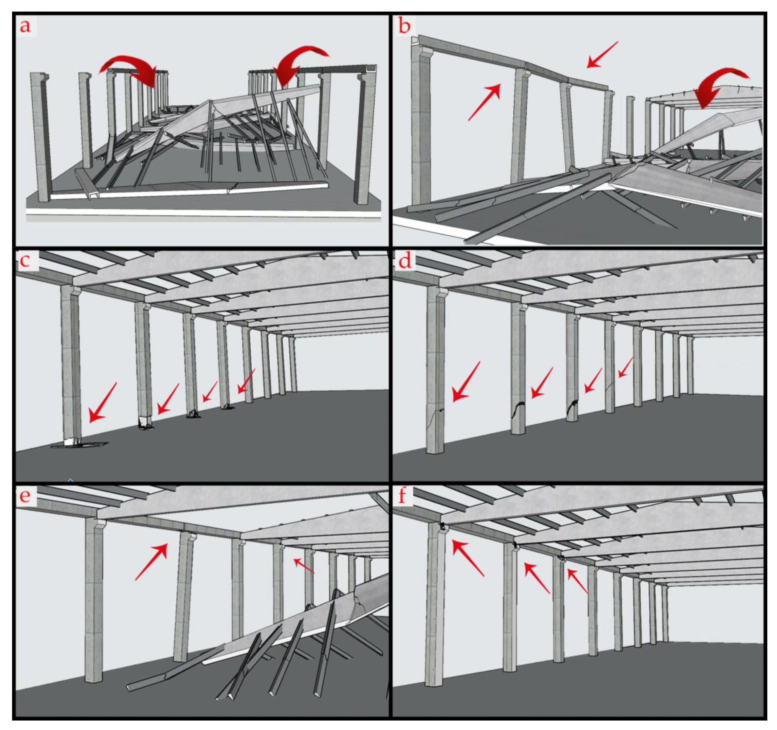
3.1. Damages Observed in Precast Buildings
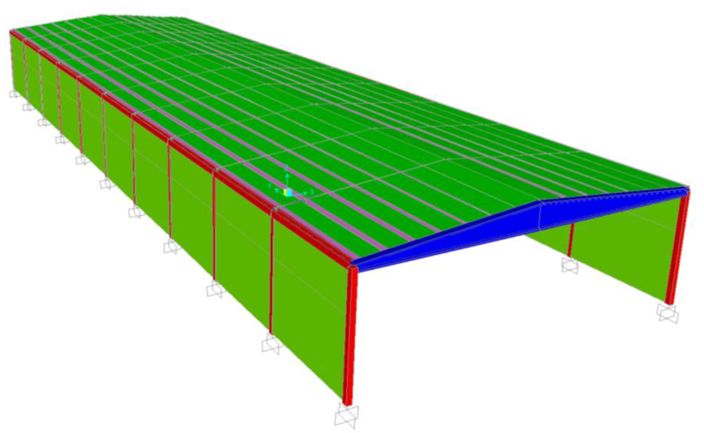
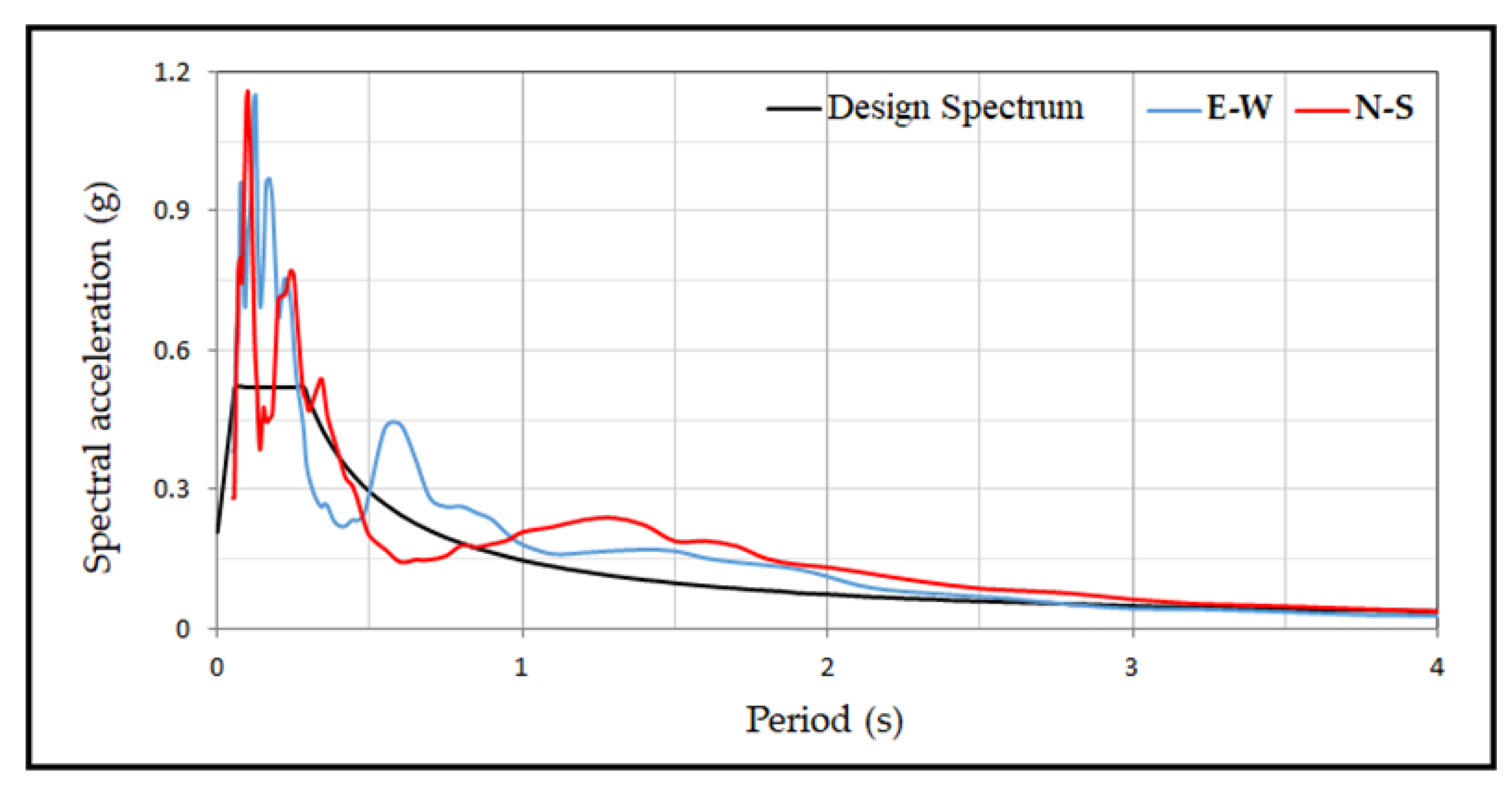
3.2. Analysis of Sample Precast Model
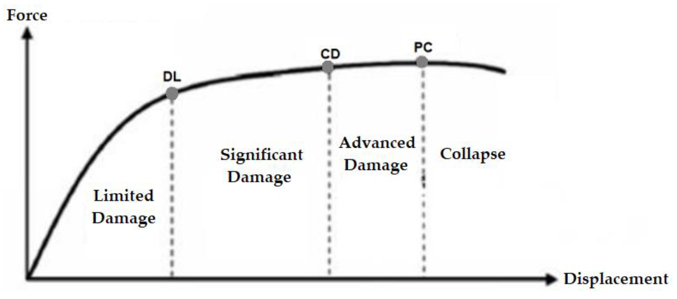
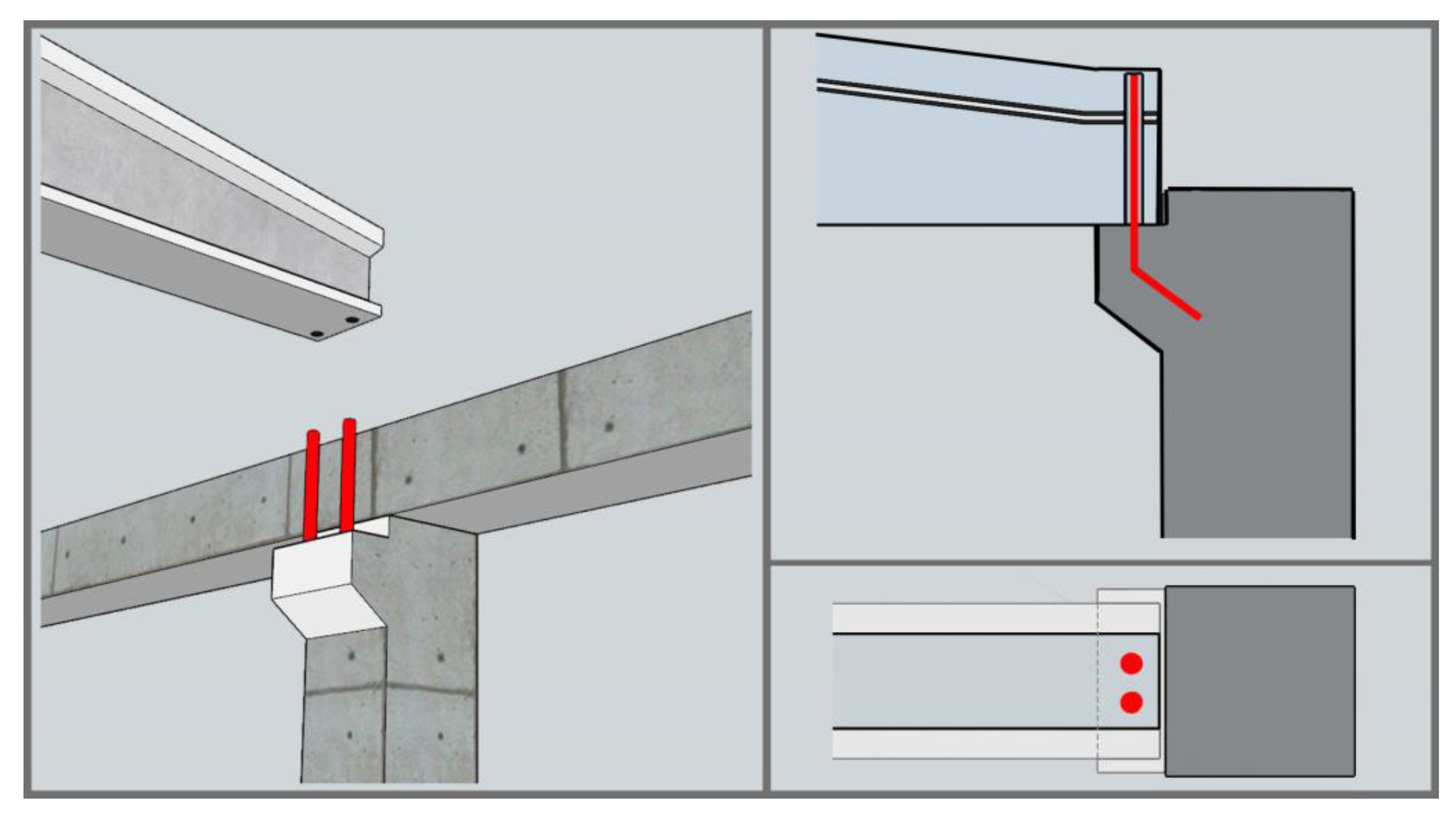
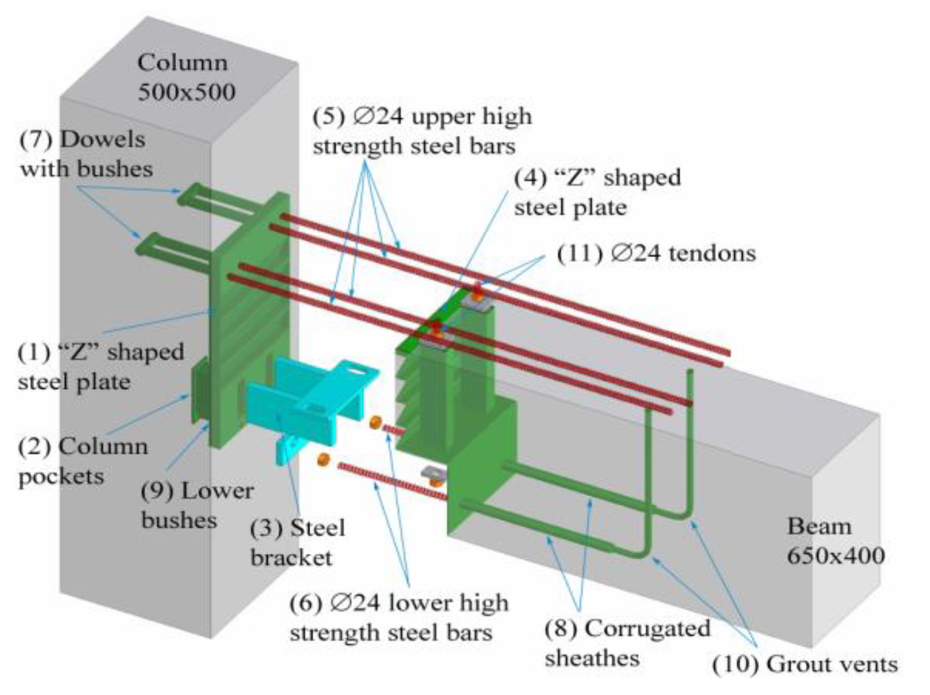
3.3. Strengthening and Improvement Recommendations
4. Conclusions
Funding
Institutional Review Board Statement
Informed Consent Statement
Data Availability Statement
Acknowledgments
Conflicts of Interest
References
- Strategy and Budget Office of the Turkish Presidency, United Nations Development Programme, the European Union, World Bank. Türkiye Earthquakes Recovery and Reconstruction Assessment. Available online: https://www.sbb.gov.tr (accessed on 12 September 2023).
- Işık, E.; Avcil, F.; Büyüksaraç, A.; İzol, R.; Arslan, M.H.; Aksoylu, C.; Harirchian, E.; Eyisüren, O.; Arkan, E.; Güngür, M.Ş.; et al. Structural damages in masonry buildings in Adıyaman during the Kahramanmaraş (Turkiye) earthquakes (Mw 7.7 and Mw 7.6) on 06 February 2023. Eng. Fail. Anal. 2023, 151, 107405. [Google Scholar] [CrossRef]
- Ozturk, M.; Arslan, M.H.; Dogan, G.; Ecemis, A.S.; Arslan, H.D. School buildings performance in 7.7 Mw and 7.6 Mw catastrophic earthquakes in southeast of Turkey. J. Build. Eng. 2023, 107810. [Google Scholar] [CrossRef]
- ODTÜ-DMAM. 6 Şubat 2023 Kahramanmaraş-Pazarcık Mw = 7.7 ve Elbistan Mw = 7.6 Depremleri Ön Değerlendirme Raporu, Deprem Mühendisliği Araştırma Merkezi. 2023. Available online: https://eerc.metu.edu.tr/tr/system/files/documents/DMAM_2023_Kahramanmaras-Pazarcik_ve_Elbistan_Depremleri_Raporu_TR_final.pdf (accessed on 1 September 2023).
- KTU. 6 Şubat 2023 Kahramanmaraş-Pazarcık Mw = 7.7 ve Elbistan Mw = 7.6 Depremleri ve Artçılarını, Saha Gözlemlerini, Yapısal Hasarları ve İleriye Yönelik Önerileri İçeren Değerlendirme Raporu. 2023. Available online: https://ktu.edu.tr/apps/file/KahramanmarasDeprem.pdf (accessed on 1 September 2023).
- Hadjian, A.H. The Spitak, Armenia earthquake of 7 December 1988—Why so much destruction. Soil. Dyn. Earthq. Eng. 1993, 12, 1–24. [Google Scholar] [CrossRef]
- Saatcioglu, M.; Mitchell, D.; Tinawi, R.; Gardner, N.J.; Gillies, A.G.; Ghobarah, A.; Anderson, D.L.; Lau, D. The August 17, 1999, Kocaeli (Turkey) earthquake damage to structures. Can. J. Civ. Eng. 2001, 28, 715–737. [Google Scholar] [CrossRef]
- Yüksel, E.; Sürmeli, M. Failure analysis of one-story precast structures for near-fault and far-fault strong ground motions. Bull. Earthq. Eng. 2010, 8, 937–953. [Google Scholar] [CrossRef]
- Sezen, H.; Whittaker, A.S. Seismic performance of industrial facilities affected by the 1999 Turkey earthquake. J. Perform. Constr. Facil. 2006, 20, 28–36. [Google Scholar] [CrossRef]
- Magliulo, G.; Ercolino, M.; Petrone, C.; Coppola, O.; Manfredi, G. The Emilia earthquake: Seismic performance of precast reinforced concrete buildings. Earthq. Spectra. 2014, 30, 891–912. [Google Scholar] [CrossRef]
- Bournas, D.A.; Negro, P.; Taucer, F.F. Performance of industrial buildings during the Emilia earthquakes in Northern Italy and recommendations for their strengthening. Bull. Earthq. Eng. 2014, 12, 2383–2404. [Google Scholar] [CrossRef]
- Minghini, F.; Ongaretto, E.; Ligabue, V.; Savoia, M.; Tullini, N. Observational failure analysis of precast buildings after the 2012 Emilia earthquakes. Earthq. Struct. 2016, 11, 327. [Google Scholar] [CrossRef]
- Savoia, M.; Buratti, N.; Vincenzi, L. Damage and collapses in industrial precast buildings after the 2012 Emilia earthquake. Eng. Struct. 2017, 137, 162–180. [Google Scholar] [CrossRef]
- Ozden, S.; Akpinar, E.; Erdogan, H.; Atalay, H.M. Performance of precast concrete structures in October 2011 Van earthquake, Turkey. Mag. Concr. Res. 2014, 66, 543–552. [Google Scholar] [CrossRef]
- Henry, R.S.; Dizhur, D.; Elwood, K.J.; Hare, J.; Brunsdon, D. Damage to concrete buildings with precast floors during the 2016 Kaikoura earthquake. Bull. N. Z. Soc. Earthq. Eng. 2017, 50, 174–186. [Google Scholar] [CrossRef]
- Pekgökgöz, R.K.; Avcil, F. Şanlıurfa 2. Organize Sanayi Bölgesindeki Bir Prefabrik Yapının Göçme Nedenlerinin Araştırılması. Fırat Univ. J. Eng. Sci. 2017, 29, 45–51. [Google Scholar]
- Pierdicca, A.; Clementi, F.; Maracci, D.; Isidori, D.; Lenci, S. Damage detection in a precast structure subjected to an earthquake: A numerical approach. Eng. Struct. 2016, 127, 447–458. [Google Scholar] [CrossRef]
- Guo, M.; Huang, H.; Zhang, W.; Xue, C.; Huang, M. Assessment of RC frame capacity subjected to a loss of corner column. J. Struct. Eng. 2022, 148, 04022122. [Google Scholar] [CrossRef]
- Huang, H.; Guo, M.; Zhang, W.; Huang, M. Seismic behavior of strengthened RC columns under combined loadings. J. Bridge Eng. 2022, 27, 05022005. [Google Scholar] [CrossRef]
- Liu, C.; Peng, Z.; Cui, J.; Huang, X.; Li, Y.; Chen, W. Development of crack and damage in shield tunnel lining under seismic loading: Refined 3D finite element modeling and analyses. Thin-Walled Struct. 2023, 185, 110647. [Google Scholar] [CrossRef]
- Tian, L.M.; Li, M.H.; Li, L.; Li, D.Y.; Bai, C. Novel joint for improving the collapse resistance of steel frame structures in column-loss scenarios. Thin-Walled Struct. 2023, 182, 110219. [Google Scholar] [CrossRef]
- Cao, X.Y. An Iterative PSD-Based Procedure for the Gaussian Stochastic Earthquake Model with Combined Intensity and Frequency Nonstationarities: Its Application into Precast Concrete Structures. Mathematics 2023, 11, 1294. [Google Scholar] [CrossRef]
- Özkılıç, Y.O.; Yazman, Ş.; Aksoylu, C.; Arslan, M.H.; Gemi, L. Numerical investigation of the parameters influencing the behavior of dapped end prefabricated concrete purlins with and without CFRP strengthening. Constr. Build. Mater. 2021, 275, 122173. [Google Scholar] [CrossRef]
- Cao, X.Y.; Wu, G.; Ju, J.W.W. Seismic performance improvement of existing RCFs using external PT-PBSPC frame sub-structures: Experimental verification and numerical investigation. J. Build. Eng. 2022, 46, 103649. [Google Scholar] [CrossRef]
- Xu, J.G.; Cao, X.Y.; Shi, J.; Wang, Z. A comparative study of the novel externally-attached precast SRC braced-frames for seismic retrofitting under near-field spectrum-compatible non-stationary stochastic earthquake. Structures 2023, 50, 200–214. [Google Scholar] [CrossRef]
- Ergin, K.; Güclü, U.; Uz, Z. A catalogue of earthquakes of Turkey and surrounding area (11 A.D. to 1964 A.D.). Tech. Univ. Istanb. Min. Eng. 1964, 24. [Google Scholar]
- Ambraseys, N.N. Some characteristic features of the Anatolian fault zone. Tectonophysics 1970, 9, 143–165. [Google Scholar] [CrossRef]
- Poirier, J.P.; Taher, M.A. Historical seismicity in the near and Middle East, North Africa, and Spain from Arabic documents (VIIth-XVIIIth century). Bull. Seismol. Soc. Am. 1980, 70, 2185–2201. [Google Scholar] [CrossRef]
- Soysal, H.; Sipahioglu, S.; Kolcak, D.; Altinok, Y.; Türkiye ve Çevresinin Tarihsel Deprem Kataloğu (MÖ 2100-MS 1900), TUBITAK Project Tbag 341 İstanbul. Turkey. 1981. Available online: https://search.trdizin.gov.tr/tr/yayin/detay/602816/turkiye-ve-cevresinin-tarihsel-deprem-katalogu-mo-2100-ms-1900 (accessed on 1 September 2023).
- Ambraseys, N.N.; Jackson, J.A. Faulting associated with historical and recent earthquakes in the Eastern Mediterranean region. Geophys. J. Int. 1998, 133, 390–406. [Google Scholar] [CrossRef]
- Alkan, H.; Büyüksaraç, A.; Bektaş, Ö.; Işık, E. Coulomb stress change before and after 24.01. 2020 Sivrice (Elazığ) Earthquake (Mw = 6.8) on the East Anatolian Fault Zone. Arab. J. Geosci. 2021, 14, 1–12. [Google Scholar] [CrossRef]
- Işık, E.; Avcil, F.; Arkan, E.; Büyüksaraç, A.; İzol, R.; Topalan, M. Structural Damage Evaluation of Mosques and Minarets in Adıyaman due to the 06 February 2023 Kahramanmaraş Earthquakes. Eng. Fail. Anal. 2023, 151, 107345. [Google Scholar] [CrossRef]
- Işik, E.; Büyüksaraç, A.; Avcil, F.; Arkan, E.; Ulu, A.E.; Aydin, M.C. Damage evaluation of masonry buildings during Kahramanmaraş (Türkiye) earthquakes on 6 February 2023. Earthq. Struct. 2023, 25, 209–221. [Google Scholar] [CrossRef]
- TC SBB, 2023 Kahramanmaraş ve Hatay Depremleri Raporu. 2023. Available online: https://www.sbb.gov.tr/wp-content/uploads/2023/03/2023-Kahramanmaras-ve-Hatay-Depremleri-Raporu.pdf (accessed on 1 September 2023).
- TBEC. Turkish Building Earthquake Code; T.C. Resmi Gazete: Ankara, Turkey, 2018. [Google Scholar]
- Computers and Structures Inc. SAP2000 Basic Analysis Reference Manual, Version 19; Berkley, CA, USA. 2006. Available online: https://docs.csiamerica.com/manuals/sap2000/CSiRefer.pdf (accessed on 1 September 2023).
- Girgin, S.C.; Göksoy, C.; Daş, E.; Mısır, İ.S. Seismic performance evaluation of a precast concrete structure with deformation-based limit criterions. J. Struct. Eng. 2021, 4, 140–150. [Google Scholar] [CrossRef]
- Magliulo, G.; Ercolino, M.; Manfredi, G. Influence of cladding panels on the first period of one-story precast buildings. Bull. Earthq. Eng. 2015, 13, 1531–1555. [Google Scholar] [CrossRef]
- Işık, M.F.; Işık, E.; Bülbül, M.A. Application of iOS/Android based assessment and monitoring system for building inventory under seismic impact. Gradjevinar 2018, 70, 1043–1056. [Google Scholar] [CrossRef]
- Büyüksaraç, A.; Isik, E.; Harirchian, E. A case study for determination of seismic risk priorities in Van (Eastern Turkey). Earthq. Struct. 2021, 20, 445–455. [Google Scholar] [CrossRef]
- Bai, Z.; Liu, T.; Zou, D.; Zhang, M.; Zhou, A.; Li, Y. Image-based reinforced concrete component mechanical damage recognition and structural safety rapid assessment using deep learning with frequency information. Autom. Constr. 2023, 150, 104839. [Google Scholar] [CrossRef]
- Arkan, E.; Işık, E.; Harirchian, E.; Topçubaşı, M.; Avcil, F. Architectural Characteristics and Determination Seismic Risk Priorities of Traditional Masonry Structures: A Case Study for Bitlis (Eastern Türkiye). Buildings 2023, 13, 1042. [Google Scholar] [CrossRef]
- Arslan, M.H.; Korkmaz, H.H.; Gulay, F.G. Damage and failure pattern of prefabricated structures after major earthquakes in Turkey and shortfalls of the Turkish Earthquake code. Eng. Fail. Anal. 2006, 13, 537–557. [Google Scholar] [CrossRef]
- Metelli, G.; Riva, P. Behaviour of a beam to column “dry” joint for precast concrete elements. In Proceedings of the 14th World Conference on Earthquake Engineering, Beijing, China, 12–17 October 2008. [Google Scholar]
- Farsangi, E. Connections behaviour in precast concrete structures due to seismic loading. Gazi Univ. J. Sci. 2010, 23, 315–325. [Google Scholar]
- Choi, H.K.; Choi, Y.C.; Choi, C.S. Development and testing of precast concrete beam-to-column connections. Eng. Struct. 2013, 56, 1820–1835. [Google Scholar] [CrossRef]
- Al-Salloum, Y.A.; Alrubaidi, M.A.; Elsanadedy, H.M.; Almusallam, T.H.; Iqbal, R.A. Strengthening of precast RC beam-column connections for progressive collapse mitigation using bolted steel plates. Eng. Struct. 2018, 161, 146–160. [Google Scholar] [CrossRef]
- Shannag, M.J.; Higazey, M. Strengthening and repair of a precast reinforced concrete residential building. Civ. Eng. J. 2020, 6, 2457–2473. [Google Scholar] [CrossRef]
- Huang, H.; Li, M.; Zhang, W.; Yuan, Y. Seismic behavior of a friction-type artificial plastic hinge for the precast beam–column connection. Arch. Civ. Mech. 2022, 22, 201. [Google Scholar] [CrossRef]
- Alver, N.; Selman, M.E.; Akgun, O.B. The effect of short cantilever beam formation on the structural behavior of precast post-tensioned connections. Constr. Build Mater. 2012, 35, 232–239. [Google Scholar] [CrossRef]


| Mode | Frequency (Hz) | Period (s) |
|---|---|---|
| 1 | 0.810373 | 1.234 |
| 2 | 3.174603 | 0.315 |
| 3 | 3.225806 | 0.310 |
| 4 | 3.311258 | 0.302 |
| 5 | 3.424658 | 0.292 |
| 6 | 3.571429 | 0.280 |
| 7 | 3.717472 | 0.269 |
| 8 | 3.846154 | 0.260 |
| 9 | 3.968254 | 0.252 |
| 10 | 4.065041 | 0.246 |
| Performance Levels (%) | Analysis Result (%) | |
|---|---|---|
| 3.78 | 5.04 | 3.56 |
Disclaimer/Publisher’s Note: The statements, opinions and data contained in all publications are solely those of the individual author(s) and contributor(s) and not of MDPI and/or the editor(s). MDPI and/or the editor(s) disclaim responsibility for any injury to people or property resulting from any ideas, methods, instructions or products referred to in the content. |
© 2023 by the author. Licensee MDPI, Basel, Switzerland. This article is an open access article distributed under the terms and conditions of the Creative Commons Attribution (CC BY) license (https://creativecommons.org/licenses/by/4.0/).
Share and Cite
Avcil, F. Investigation of Precast Reinforced Concrete Structures during the 6 February 2023 Türkiye Earthquakes. Sustainability 2023, 15, 14846. https://doi.org/10.3390/su152014846
Avcil F. Investigation of Precast Reinforced Concrete Structures during the 6 February 2023 Türkiye Earthquakes. Sustainability. 2023; 15(20):14846. https://doi.org/10.3390/su152014846
Chicago/Turabian StyleAvcil, Fatih. 2023. "Investigation of Precast Reinforced Concrete Structures during the 6 February 2023 Türkiye Earthquakes" Sustainability 15, no. 20: 14846. https://doi.org/10.3390/su152014846
APA StyleAvcil, F. (2023). Investigation of Precast Reinforced Concrete Structures during the 6 February 2023 Türkiye Earthquakes. Sustainability, 15(20), 14846. https://doi.org/10.3390/su152014846