Abstract
In this research, the mechanisms of end-grain corrosion of 304L NAG tubes in boiling 9M HNO3-containing Cr (VI) ions are reported to sustainably manage the corrosion of nuclear fuel reprocessing plant components. Specific heat treatments were applied to as-received specimens to produce phosphorus and/or sulphur intergranular segregation. End-grain corrosion on heat-treated specimens and the effect of a Cr (VI) concentration on a 304L NAG tube (as-received) were investigated. It has been reported that an increase in Cr (VI) ions leads to the acceleration of end-grain corrosion due to high electrochemical potential. After systematic heat treatments on the 304L NAG specimens, it is concluded that the primary causes of heat-induced end-grain corrosion are phosphorus or sulphur segregation to the grain boundaries. The key findings of this research are highly significant in terms of understanding the corrosion mechanisms and controlling the end-grain corrosion of NAG steel in boiling HNO3 environments. This research will help to sustainably reduce power plant maintenance costs and will have a significant impact on the delivery of long-term, clean, secure, and tenable energy.
1. Introduction
Nuclear power plants have a significant role at present and in the future to deliver long-term, secure, low-carbon, and cost-effective energy. For the future of nuclear energy, it is important to ensure nuclear power plants have a sustainable strategy, which have the best prospect of reaching their full capacity and potential [1]. The effective management of ageing systems, structures, and components is increasingly becoming important. Ageing is a major concern for the operating organization and there is a need to devote significant resources to managing ageing systems, including the resources for investigation and understanding and preventing system deterioration [1,2].
This article is part of our wider research to develop sustainable methods for the protection of high-value structures, in terms of their ageing prediction and prevention of material deterioration due to corrosion failures [3,4,5,6,7,8,9,10,11,12,13,14,15,16,17,18,19,20,21,22,23,24,25,26,27,28,29,30,31].
Austenitic stainless steel (SS) is widely used in reprocessing and waste management operations to deal with irradiated nuclear fuel. Austenitic SS alloys are characteristically developed with regulated chemical compositions, which are improved microstructures that eliminate weaker locations for passive film disintegration, dissolution, and increased resistance to trans-passive dissolution, and are also known as nitric acid grade (NAG) austenitic stainless-steel alloys. Many NAG alloys with similar compositions to 304L, 310L, and proprietary alloys are created for use in the reprocessing industry [32,33,34].
Up to 9 mole (mole is the unit of the amount of a substance or a measure of how many elementary entities of a given substance are in a sample) nitric acid (9M HNO3) concentrations and temperatures reaching their boiling points are used as a process fluid within nuclear-expended fuel reclaiming and the corresponding waste-related management operations. Process fluid contains oxidising fission-based products (Ce4+) and corrosion products (Cr6+ and Fe3+). Some components employ evaporation to lower the amount of process fluid over multiple cycles. This causes the concentration of these oxidising ions to rise over time.
Austenitic SS in a sensitised condition is susceptible to intergranular corrosion (IGC) in a boiling HNO3 atmosphere [1,2,32,33,34]. Even non-sensitised SS is vulnerable to IGC and end-grain or tunnel corrosion in boiling HNO3 containing oxidising ions. This starts from the grain’s terminal as a localised pitting attack and expands along the hot working direction, eventually leading to intergranular corrosion. End-grain corrosion in austenitic SS in HNO3 is probably the most well-known case. It should be mentioned here that this is not peculiar to austenitic SS in HNO3; the exfoliation corrosion of high-strength aluminium alloys is morphologically like end-grain corrosion and is common in high-humidity, salty conditions. End-grain corrosion is a special form of IGC; when seen from the surface side of the component, it looks like IGC but is highly localised. End-grain corrosion can be identified by cutting the affected component in longitudinal sections and metallographically analysing it. Sometimes it can be polished off before morphological examinations and remains undetected. Exfoliation corrosion can occur in rolled or extruded aluminium alloys with elongated and flattened grains [35]. Parts such as tubes and pipes are particularly susceptible to corrosion due to the end-grain. Reprocessing uses SS alloys to resist sensitisation; end-grain corrosion has been recognised as the main deterioration mechanism in several components, for example, in tubing and sheet-welded tube to tube (L grade or NAG) pipes. Even with the NAG of SS, exposure investigations in reprocessing and dissolver plants (in the vapour phase) displayed an increased rate of corrosion of 0.6–2 mm-y−1, which was primarily due to end-grain corrosion [36].
Stringer (sulphides or oxysulphides of manganese and iron) inclusions have been proven to generate IGC in austenitic SS in previous studies [37,38,39,40,41]. Due to the existence of these inclusions, the corrosion rates of sensitised SS dramatically increase. The exposed end (cross-sectional) faces of stringers (sulphide inclusions) dissolve due to the dissolution of inclusions. Cr6+ ions accumulate within the emerging cavities and corrosion accelerates in the high-energy grain boundaries, resulting in IGC.
This acceleration can be reduced by introducing the ASTM total inclusion rating for an NAG of less than 4.5. The sulphide form of inclusions, often recognised as dynamic inclusions, must be circumvented. Controlled oxygen and sulphur expanses in NAG SS help to prevent inclusions. Manganese sulphide inclusions do not occur when sulphur and manganese levels are low. Other inclusions are kept at bay by keeping the dissolved oxygen content of the SS below 0.01 per cent, preferably below 50 ppm. Cold-working and insufficient solution annealing can also promote end-grain corrosion in austenitic SS, causing a corrosion attack on segregated elements along accumulated dislocations. In 9M HNO3 + 1g Cr6+ L−1, Kain et al. [38] evaluated 304L’s and 304L NAG’s susceptibility to end-grain corrosion. When comparing 304L NAG with 304L, they found that 304L NAG was substantially less susceptible to end-grain corrosion [38].
Limited research has been reported so far to provide a complete understanding of the end-grain corrosion mechanisms of NAG steel. The main drive of this research was to understand the non-sensitised stainless steel end-grain corrosion of the near-boiling HNO3 conditions at the trans-passive potential regime. The as-received samples were heat-treated and further evaluated to understand the degree of sensitization, end-grain corrosion at different concentrations of Cr (VI) ions, and effects of various heat treatments to realise the segregation of chemical elements at grain boundaries.
2. Experimental Methodology
2.1. Material Selection and Heat Treatment
In this study, the sample was a 304L NAG tube with 2.5 cm outside and 1.6 cm inner diameters. The chemical composition (weight percentage) was Cr 18, Mn 1.17, Ni 10.87, C 0.012, S 0.003, P 0.018, Si 0.25, and Fe (balance). Several sets of 304 L NAG tubes were subjected to various heat treatments, and after the heat treatments, specimens were water-quenched. To induce the intended microstructural changes in different sets of samples, a combination of temperatures and times of 675 °C for 1 h, 650 °C sustained for 3 h, 650 °C carried for 100 h, and 990 °C for 5 min were chosen. Other test specimens that had already undergone heat treatment at 650 °C for 100 h were further heat-treated for an additional 90 min at 950 °C.
2.2. Degree of Sensitisation
ASTM A 262 standard practices for detecting the susceptibility to intergranularity in austenitic stainless steel was applied to the heat-treated and as-received specimens to evolve the microstructures. Cold-setting resin was used for mounting cross-sectional and longitudinal sections of the as-received and heat-treated specimens, as shown in Figure 1. Diamond paste was used to polish the specimens after grinding them with silicon carbide sheets to a 1 µm finish. Degreasing was followed by rinsing with deionised water, drying in acetone, and electrolytic etching with a solution containing 10% oxalic acid for 90 s at a 1 A cm2 current density as per the ASTM A 262 test [42].
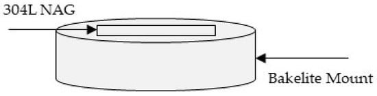
Figure 1.
Sample Schematic of 304L NAG for ASTM A262 Test.
Figure 2 shows the specimen with a spot-welded stainless steel wire in an insulated sleeve. A potentio-kinetic reactivation electrochemical test with a double-loop (DL-EPR) was conducted for determining the degree of sensitisation (DOS) of the sample [43,44,45] by using stainless steel as a working electrode. Platinum counter electrodes were used while the reference electrode was a saturated calomel (SCE). The test solution contained a deaerated mix of potassium thiocyanate (KSCN) and sulphuric acid (H2SO4) with concentrations of 0.01 M and 0.5 M, respectively. Equation (1) was employed to calculate the value of the DOS:
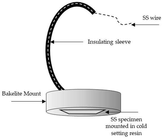
Figure 2.
Specimen Schematic for DL–EPR Investigation.
ir & ia represent the highest currents in reverse (reactivation) and forward (anodic) scans, respectively.
2.3. ASTM A 262 Practice C
This methodology consisted of testing the original and heat-treated 304L NAG tube specimens at 650 °C for 100 h and 990 °C for 5 min, respectively. Each material was tested with two specimens. The specimen’s cross-sectional area was chosen to equal 32% of the total surface area. The goal of this test was to see if these specimens could be affected by IGC in HNO3. This test was conducted using an Erlenmeyer flask with a cold-finger-type condenser, as shown in Figure 3. For 240 h, the specimens were subjected to boiling HNO3 to a concentration of 65 per cent (48 h × 5 periods). Fresh HNO3 was utilised in each period. Chromium carbide, chromium deficient zones, and the sigma phase are all dissolved by it [46]. The surface-to-volume ratio of the specimen and solution is significant in terms of corrosion rates; as the surface-to-volume ratio increases, corrosion rates; hence, it is recommended that this ratio be kept at 20 mL cm−2 [42]. By applying Equation (2), the weight loss measured after each interval was used to compute the corrosion rates:
r = 87,480 × W/A × d × t
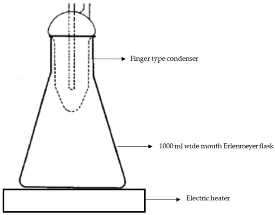
Figure 3.
Experimental setup schematic used for conducting ASTM A 262 Practice C and end-grain corrosion tests.
The corrosion rate of each session, as well as the average of five or 3 periods, are presented in the test results.
Acceptable corrosion rates for construction materials in reprocessing plants are determined by the location of the equipment (in or out of the cell) and the service fluid. Corrosion rates for critical equipment such as dissolvers, on the other hand, are limited to 10 mpy.
2.4. End-Grain Corrosion Test
The cross-sectional area of the specimen was chosen to be 32 per cent of the overall surface area of the specimen. Heat treatments were applied to the sample (mentioned in Section 2.1). To polish the specimens, silicon carbide papers were used with gradually finer grits until they reached 600 grits, followed by cleaning with a soap solution and drying with acetone. Cold-setting resin was used to mount longitudinal sections of specimens, while emery paper was used to polish the surface to 1 µm. This allowed the morphology of the pitting attacks to be studied. Optical microscopy and SEM were used to study the surface morphology of the samples.
In both their original states and after selective heat treatment, clean and dried specimens were tested for end-grain corrosion. The test setup and specimen preparation were identical to ASTM A 262 Practice C, which is provided in Figure 3.
Specimens were subjected to 9M HNO3 + 1 g L−1 Cr6+ solutions at boiling temperatures for 24 h spanning 4 periods to assess the influence of microstructural changes on end-grain corrosion. The as-received specimens were exposed to the following conditions to study the effect of Cr6+ concentration on end-grain corrosion:
9M HNO3 + 1 g L−1 Cr6+, 4 periods each of 3 h duration;
9M HNO3 + 1.25 g L−1 Cr6+, 20 periods each of 3 h duration;
9M HNO3 + 1.5 g L−1 Cr6+, 20 periods each of 3 h duration;
Weight loss measurements after each end-grain corrosion test were used to calculate the corrosion rate.
2.5. Measurement of Potential in End-Grain Corrosion Test Solution
The experimental setup to measure potential was identical to that used in a previous study [46]. For electrode potential measurements in boiling acid, Streicher employed a similar setup [47]. Due to the extremely conductive nature of the solution, no temperature or junction potential modifications were made.
3-electrode systems consist of (a) a working electrode (the specimen under study), (b) a non-polarisable counter electrode for completing the circuit (platinum foil), and (c) a reference electrode (a saturated calomel electrode). In this setup, the calomel electrode was kept in a beaker filled with a saturated potassium chloride solution. The calomel electrode was not directly immersed in near-boiling HNO3; hence, an acid bridge was used to create electrical contact. At room temperature, another beaker was filled with the test solution. By adjusting the voltage supply to the heating mantle, the temperature of the test solution in a conical flask was kept near boiling.
The as-received materials were cut into test specimens with a 14 per cent ratio of total surface cross-sectional area. The specimens were grounded using various types of emery papers to obtain 600 grits. Smoothing was applied to the edges and corners. The polished samples were conditioned with water rinsing. These samples were then treated with acetone and exposed to a dryer for drying. To provide electrical contact, an SS wire was spot-welded over the specimens on one side. An insulative sheathing was used to cover the connecting wire, and polytetrafluoroethylene (PTFE) tape was used to isolate the contact surfaces between the wire and specimen. Using a portable field potentiostat, the potential developed in the various solutions 9M HNO3 + 1 g L−1 Cr6+, 9M HNO3 + 1.25 g L−1 Cr6+, and 9M HNO3 + 1.5 g L−1 Cr6+ were measured in a different test.
2.6. Study of Morphology of End-Grain Corrosion
Specimens were mounted in cold-setting resin to investigate the end-grain corrosion morphology. These samples were conditioned to a 1 µm finish. The polished samples were then degreased using a soap solution and rinsed by applying water. These samples were then dried by acetone spewing and etched for 20 s in a 10% oxalic acid solution. Optical and electron microscopy were utilised for investigating the surface morphology of the corrosion attack using backscattered electron imaging (BEI) and secondary electron imaging (SEI) techniques. Electron beam energy was kept at 20 kV. The depth of “End Grain Corrosion” was measured using the optical microscope’s built-in scale.
3. Results and Discussion
3.1. Degree of Sensitisation
Figure 4a demonstrates a 304L NAG tube in a non-sensitised condition with a step microstructure after electro-etching in 10% oxalic acid. The step microstructure was converted to a dual microstructure after heating the samples at 650 °C for 3 h, as shown in Figure 4b. A dual microstructure was observed in the as-received specimens, which had been heat-treated at 650 °C for 100 h, as shown in Figure 4c. Thermal treatment at 950 °C for 90 min of previously heat-treated samples at 650 °C for 100 h converted the dual microstructure to a step microstructure without any change to the grain size (Figure 4d). The samples heat treated at 990 °C for 5 min exhibited a step microstructure, as shown in Figure 4e.
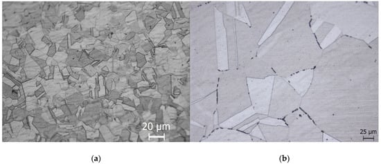
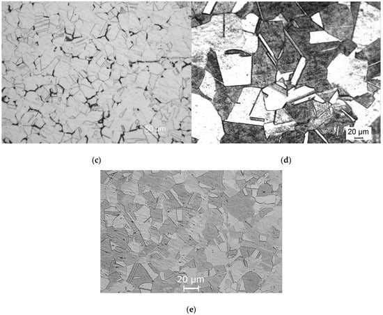
Figure 4.
Type 304L NAG tube microstructures after (a) receiving condition and (b) under 650 degrees Celsius for 3 h, (c) 650 degrees Celsius for 100 h, (d) 650 degrees Celsius for 100 h, followed by (e) 950 degrees Celsius for 90 min, and 5 min at 990 degrees Celsius.
In Table 1, the values of the degree of sensitisation (DOS) for the as-received heat-treated samples evaluated from the DL-EPR test are provided. The as-received specimen showed a very low value of DOS, which corresponded to a step microstructure. A slight increase in the DOS value was observed after a heat treatment of 650 °C for 3 h. The microstructure after the DL-EPR testing of heat-treated specimens at 650 °C for 3 h was slightly dual. When the duration of the heat treatment was increased from 3 to 100 h at 650 °C, the DOS value increased from 0.18 to 1.4. It was confirmed by the microstructure after the DL-EPR test that the DOS value of 1.4 corresponded to a dual microstructure. An annealing heat treatment at 950 °C for 90 min on test samples that were previously heat-treated at 650 °C for 100 h brought down the DOS from 1.4 to 0.06. The value of the DOS was 0.13 for the samples heat-treated at 990 °C for 5 min. It is evident from the above discussion that the as-received and heat-treated samples showed low DOS values, which corresponded to either step or dual microstructures. In other words, no heat treatment resulted in severe sensitisation with a ditch microstructure. Figure 5 shows the result of ASTM A 262 Practice C conducted on a type 304 L NAG tube in the as-received samples form and after a 650 °C heat treatment for 100 h and 675 °C for 1 h. It is evident from the graph that the average corrosion rate was far below 18 mpy (12). Therefore, the as-received type 304 L NAG tube form and after heat treatment at 650 °C for 100 h and 675 °C for 1 h can be safely used for boiling nitric acid applications.

Table 1.
Degree of sensitisation (DOS) evaluated from DL-EPR test of 304L NAG tubes in the as-received condition post heat treatment.
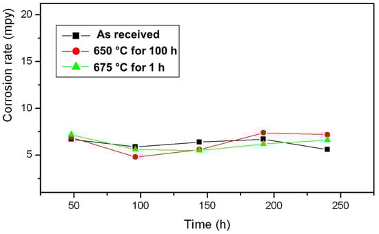
Figure 5.
Results of ASTM A262 Practice C, conducted on a 304 L NAG tube in the as-received condition and after heat treatment.
3.2. End-Grain Corrosion at Different Concentrations of Cr6+
According to Figure 6, corrosion rates of 304L NAG tube specimens in boiling 9M HNO3 at various concentrations of Cr6+ are shown as functions of time. As the Cr6+ concentration increased, the corrosion rate increased. The highest corrosion rate was observed in specimens subjected to 9M HNO3 containing 1.5 gL−1 Cr6+, whereas the lowest corrosion rate was observed in specimens exposed to 9M HNO3 containing 1gL−1 Cr6+. All 3 specimens showed a tendency of increasing corrosion rates with respect to time. The corrosion rate for specimens exposed to 9M HNO3 containing 1.5 g L−1 Cr6+ was 23 mmy−1 (909 mpy) after an exposure of 57 h. Specimens exposed to 9M HNO3 containing 1.25 g L−1 Cr6+ showed a 17.4 mmy−1 (688 mpy) corrosion rate after the same time (57 h) of exposure. A corrosion rate of 8.4 mmy−1 (399 mpy) was observed after 57 h of exposure for specimens immersed in 9M HNO3 containing 1g L−1 Cr6+.
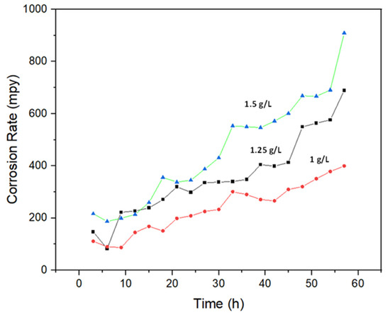
Figure 6.
An illustration of how corrosion rates differ depending on the concentration of Cr6+ in boiling 9M HNO3.
End-grain corrosion was strongly related to the corrosion attack observed in the specimen’s longitudinal direction after the end-grain corrosion test was completed. The end-grain corrosion depth for the specimen exposed to boiling 9M HNO3 containing 1.5 g L−1 Cr6+ was 475 μm. As a result of the exposure to boiling 9M HNO3 containing 1.25 g L−1 Cr6+, the depth of the end-grain corrosion was 100 µm. Figure 7 shows the Cr6+ concentrations’ potential variations with time in boiling 9M HNO3. A higher potential was recorded for the specimen exposed to boiling 9M HNO3 containing 1.5 g L−1 Cr6+, leading to a higher corrosion rate and a deep end-grain corrosion attack in this specimen.
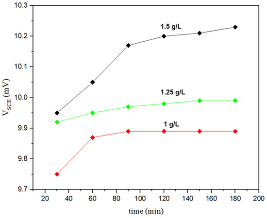
Figure 7.
Potential variation with time in boiling 9M HNO3 containing different concentrations of Cr6+.
3.3. Effect of Various Heat Treatments on End-Grain Corrosion Behaviour of a Type 304L NAG Tube
To determine whether intergranular elemental segregation impacts end-grain corrosion, the test specimens were tested after being heat-treated. The specimens were submerged in 9M HNO3 +1 g L−1 Cr6+ for four 24 h intervals. Weight loss measurements were used to calculate the rate of corrosion after each period. The outcomes of these tests are depicted in Figure 8. During the first period, the corrosion rate of the heat-treated sample at 650 °C for 100 h was 11.09 mmy−1 (437 mpy), and during the second period, the corrosion rate was 27.5 mmy−1 (1083 mpy). The sample heat-treated for 100 h at 650 °C was not subjected to end-grain corrosion experiments beyond the second period due to the excessive corrosion rate. The end-grain corrosion tests were conducted on specimens that had been heated to 650 °C for 100 h and annealed for 90 min at 950 °C. It was observed that the corrosion rate was markedly reduced after the samples were annealed at 950 °C for 90 min. In fact, of all the specimens, this one had the lowest average corrosion rate of 3.2 mmy-1 (126 mpy).
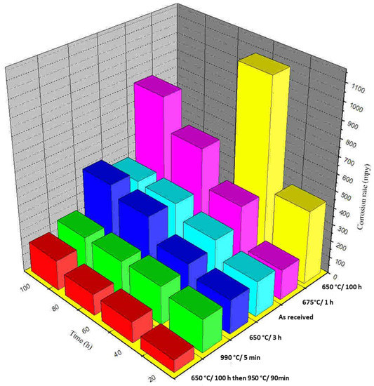
Figure 8.
A measurement of corrosion rate as a function of discrete periods evaluated by type 304L NAG specimens with a boiling 9M HNO3 + 1 g L−1 Cr6+ solution with and without heat treatment processes.
Figure 9 depicts the end-grain corrosion test’s morphology of corrosion attack, starting with the cross-section of the tube. Cross-sectional corrosion attacks propagating in the longitudinal direction were only visible at a few sites by the intergranular mode of corrosion. Therefore, it is evident that end-grain corrosion was the key element. Maximum end-grain corrosion (depth of corrosion attack), as determined by a morphological analysis, was found in the specimen that had been heat-treated for 100 h at 650 °C. The test samples that were heat-treated for 3 h at 650 °C had a lower depth of end-grain corrosion than the samples that were treated for 100 h at 650 °C. It is noted that the samples that were heated at 650 °C for 3 h and 650 °C for 100 h both showed dual microstructures. The 304L with dual microstructure was not susceptible to IGC in the ASTM A 262 Practice C test [42]. In this procedure, chromium carbide and sigma-like precipitates were detected as markers for IGC susceptibility [42]. ASTM A 262 Practice C was conducted on the specimens that were treated at 650 °C for 100 h (the highest DOS value). The average rate of corrosion in ASTM A 262 Practice C was 0.15 mmy−1 (6 mpy). This shows that the specimen was not prone to IGC due to Cr depletion. Thus, the end-grain corrosion in these specimens cannot be explained due to a dual microstructure or in other words due to Cr depletion. Phosphorus segregation increased to its maximum in austenitic stainless steel (SS), which was given heat treatment for 100 h at 650 °C [48]. The stated heat treatment induced the segregation of phosphorus, which resulted in end-grain corrosion in this specimen. The lowest corrosion rate was observed when the end-grain corrosion samples were treated for 100 h at 650 °C and annealed for 90 min at 950 °C. In addition, the end-grain corrosion depth was the least for this specimen. To equilibrate the segregation, heat treatment for 90 min at 950 °C was applied to the specimen to avoid sensitising or grain growth [50]. Therefore, end-grain corrosion was minimal in specimens that had such heat treatment. The samples that were heat-treated for 5 min at 990 °C displayed extremely deep end-grain corrosion, as shown in Figure 9. It was also demonstrated that treatment for 5 min at 990 °C resulted in the intergranular segregation of S in austenitic SS [50]. The segregation of sulphur along the grain boundaries might have been the cause of the severe end-grain corrosion observed within the specimens that were treated for 5 min at 990 °C. The corrosion rate for this specimen in the end-grain corrosion test was lower compared with that of the as-received specimen. The as-received specimen showed IGC starting from OD as well as the ID side of the tube and propagating along the thickness of the tube (Figure 10). The IGC from the OD side of the tube heat-treated at 990 °C for 5 min was not severe (IGC is shown on the ID side of the tube in Figure 10). The higher corrosion rate in the as-received specimen compared with the samples, which were heat-treated for 5 min at 990 °C, might have been due to higher IGC from the OD and ID sides of the tube. A heat treatment that has been reported to lead to the segregation of phosphorus or sulphur was shown to cause end-grain corrosion, although it was not directly linked to the segregation of phosphorus and sulphur in this study.
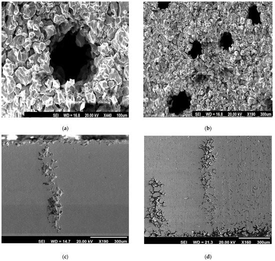
Figure 9.
SEM morphology of corrosion attack: (a) specimens thermally treated at 990 °C for 5 min, (b) cross-section of specimens with thermal treatment for 100 h at 650 °C, (c) longitudinal sections of the test specimens thermally treated at 990 °C/5 min, and (d) specimens treated for 100 h/650 °C after end-grain corrosion testing in a 9M HNO3 + 1 g L−1 Cr6+ solution at boiling temperatures.
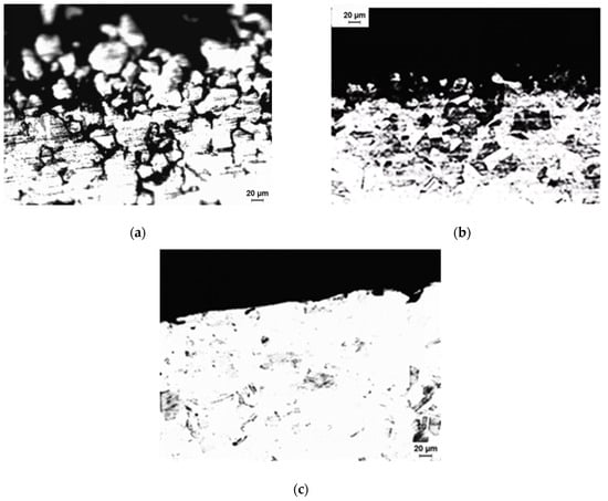
Figure 10.
As-received specimen (a) observed with an optical microscope from the OD side of the tube, (b) observed with an optical microscope from the ID side of the tube, and (c) observed after heat-treating specimens at 990 degrees Celsius for 5 min on the OD side.
As shear bands and flow lines line up in the working direction, phosphorus and sulphur are more likely to segregate. By exposing these surfaces to corrosion, the attack preferentially propagates to those regions with phosphorus segregation. Because grain boundaries (even those that are not sensitised) are high-energy boundaries, further propagation occurs through intergranular corrosion once accelerated corrosion begins at these locations.
Due to the accumulation of Cr6+ in an oxidising solution, the corrosive solution developed in these pits initiates the rapid dissolution of any material, due to trans-passive electrochemical potential [51]. In addition to preventing end-grain corrosion, a 90 min 950 °C heat treatment did not sensitise the stainless steel. This heat treatment can be applied to all stainless steels that are susceptible to end-grain corrosion to balance the segregation of phosphorus and prevent end-grain corrosion, which was demonstrated by the tests during this investigation. A salvaging 950 °C heat treatment for 90 min prevented end-grain corrosion without changing the grain size or sensitising the material.
4. Control of End-Grain Corrosion
The following methodologies can be adopted for controlling end-grain corrosion within HN03 environments [50]:
- ○
- Using lasers to remelt exposed cross-sectional surfaces was proven to prevent end-grain corrosion. An altered ferritic and cast microstructure were the primary characteristics of the laser-remelted surfaces.
- ○
- End-grain corrosion was avoided by weld-overlaying unprotected end-surfaces, such as tubular cross-sections, with welded filler material such as a 308L type or welding a ring of stainless steel, which would withstand susceptibility to end-grain corrosion over sensitive end/edge surfaces.
- ○
- Annealing with a controlled solution was applied to stainless steel that was susceptible to end-grain corrosion. This can be accomplished by annealing for 90 min at 950°C. Grain coarsening was not a problem with this heat treatment. It was shown that a 950°C heat treatment for 90 min resulted in an adequate homogenisation of alloying elements, thus erasing material segregation.
5. Conclusions
The following is a summary of the present investigation dealing with the role of the Cr6+ concentration present in HNO3 and the intergranular segregation of sulphur and phosphorus:
- An increase in Cr6+ concentration in 9M HNO3 increased the 304L NAG tube’s susceptibility to end-grain corrosion. This increase in the predisposition of end-grain corrosion of 304L NAG tubes can be attributed to an increase in electrochemical potential with an increase in Cr6+ concentrations.
- Any heat treatment used in this study did not result in extensive sensitisation and the type 304L NAG tube remained resistant to intergranular corrosion during ASTM A 262 Practices A and C.
- A significant increase in end-grain corrosion for the specimen heat-treated for 100 h at 650 °C was observed, which was taken to be due to the maximum segregation of phosphorus to the grain boundary.
- Heat treatment for 100 h at 650 °C induced a high susceptibility in terms of end-grain corrosion. Therefore, a 90 min heat treatment at 950 °C put an end to this susceptibility as a salvaging measure. This was mainly due to the equilibration of the segregation of phosphorus.
- A heat treatment at 990 °C for 5 min resulted in a high increase in end-grain corrosion. This increase in susceptibility to end-grain corrosion and can be attributed to the segregation of sulphur to the grain boundaries.
- We suggest that end-grain corrosion can be controlled by (a) the laser surface remelting of the exposed end faces, by (b) weld overlaying exposed end faces, and by (c) a controlled solution annealing the heat treatment of the as-received material.
Author Contributions
Conceptualization, A.S. and S.K.; methodology, S.K. and A.S.; validation, S.K., A.S., M.H.N., M.U.A. and Z.A.K.; formal analysis, S.K. and A.S.; investigation, S.K. and A.S.; resources, A.S.; data curation, S.K. and A.S.; writing—original draft preparation, S.K. and A.S.; writing—review and editing, S.K., A.S., M.H.N., M.U.A. and Z.A.K.; supervision, A.S. and Z.A.K.; project administration, S.K. and A.S. All authors have read and agreed to the published version of the manuscript.
Funding
This research received no external funding.
Institutional Review Board Statement
Not applicable.
Informed Consent Statement
Not applicable.
Data Availability Statement
Not applicable.
Acknowledgments
The authors would like to acknowledge Zeefam Technologies and Scientific Solutions, India for their kind support.
Conflicts of Interest
The authors declare no conflict of interest.
References
- Sedriks, A.J. Corrosion of Stainless Steels, 2nd ed.; John Wiley and Sons: New York, NY, USA, 1996. [Google Scholar]
- Cihal, V. Intergranular Corrosion of Stainless Steels and Alloys. Mater. Sci. Monogr. 1984, 18, 196. [Google Scholar]
- Nazir, M.H.; Khan, Z.A.; Saeed, A.; Stokes, K. A predictive model for life assessment of automotive exhaust mufflers subject to internal corrosion failure due to exhaust gas condensation. Eng. Fail. Anal. 2016, 63, 43–60. [Google Scholar] [CrossRef]
- Nazir, M.H.; Khan, Z.A.; Stokes, K. A holistic mathematical modelling and simulation for cathodic delamination mechanism—A novel and an efficient approach. J. Adhes. Sci. Technol. 2015, 29, 2475–2513. [Google Scholar] [CrossRef]
- Nazir, M.H.; Khan, Z.; Stokes, K. Modelling of metal-coating delamination incorporating variable environmental parameters. J. Adhes. Sci. Technol. 2014, 29, 392–423. [Google Scholar] [CrossRef]
- Nazir, M.; Khan, Z.; Saeed, A.; Stokes, K. Modelling the Effect of Residual and Diffusion induced Stresses on Corrosion at the Interface of Coating and Substrate. Corrosion 2015, 72, 500–517. [Google Scholar] [CrossRef] [PubMed]
- Nazir, M.H.; Khan, Z.A.; Stokes, K. Optimisation of Interface Roughness and Coating Thickness to Maximise Coating-Substrate Adhesion—A Failure Prediction and Reliability Assessment Modelling. J. Adhes. Sci. Technol. 2015, 29, 1415–1445. [Google Scholar] [CrossRef]
- Saeed, A.; Khan, Z.A.; Nazir, M.H. Time dependent surface corrosion analysis and modelling of automotive steel under a simplistic model of variations in environmental parameters. Mater. Chem. Phys. 2016, 178, 65–73. [Google Scholar] [CrossRef]
- Nazir, M.; Khan, Z.A.; Stokes, K. A unified mathematical modelling and simulation for cathodic blistering mechanism incorporating diffusion and fracture mechanics concepts. J. Adhes. Sci. Technol. 2015, 29, 1200–1228. [Google Scholar] [CrossRef]
- Nazir, M.H.; Khan, Z.A.; Stokes, K. Analysing the coupled effects of compressive and diffusion induced stresses on the nucleation and propagation of circular coating blisters in the presence of micro-cracks. Eng. Fail. Anal. 2016, 70, 1–15. [Google Scholar] [CrossRef]
- Nazir, M.H.; Saeed, A.; Khan, Z. A comprehensive predictive corrosion model incorporating varying environmental gas pollutants applied to wider steel applications. Mater. Chem. Phys. 2017, 193, 19–34. [Google Scholar] [CrossRef]
- Nazir, M.; Khan, Z. A review of theoretical analysis techniques for cracking and corrosive degradation of film-substrate systems. Eng. Fail. Anal. 2016, 82, 80–113. [Google Scholar] [CrossRef]
- Bajwa, R.; Khan, Z.; Nazir, H.; Chacko, V.; Saeed, A. Wear and Friction Properties of Electrodeposited Ni-Based Coatings Subject to Nano-Enhanced Lubricant and Composite Coating. Acta Metall. Sin. Engl. Lett. 2016, 29, 902–910. [Google Scholar] [CrossRef]
- Nazir, M.H.; Khan, Z. Maximising the interfacial toughness of thin coatings and substrate through optimisation of defined parameters. Int. J. Comput. Methods Exp. Meas. 2015, 3, 316–328. [Google Scholar] [CrossRef]
- Bajwa, R.S.; Khan, Z.; Bakolas, V.; Braun, W. Effect of bath ionic strength on adhesion and tribological properties of pure nickel and Ni-based nanocomposite coatings. J. Adhes. Sci. Technol. 2016, 30, 653–665. [Google Scholar] [CrossRef]
- Bajwa, R.S.; Khan, Z.; Bakolas, V.; Braun, W. Water-Lubricated Ni-Based Composite (Ni–Al2O3, Ni–SiC and Ni–ZrO2) Thin Film Coatings for Industrial Applications. Acta Metall. Sin. Engl. Lett. 2015, 29, 8–16. [Google Scholar] [CrossRef]
- Nazir, M.H.; Khan, Z.A.; Saeed, A.; Bakolas, V.; Braun, W.; Bajwa, R.; Rafique, S. Analyzing and modelling the corrosion behavior of Ni/Al2O3, Ni/SiC, Ni/ZrO2 and Ni/Graphene nanocomposite coatings. Materials 2017, 10, 1225. [Google Scholar] [CrossRef]
- Khan, Z.A.; Grover, M.; Nazir, M.H. The implications of wet and dry turning on the surface quality of EN8 steel. In Transactions on Engineering Technologies; Springer: Dordrecht, The Netherlands, 2015; pp. 413–423. [Google Scholar]
- Khan, Z.A.; Chacko, V.; Nazir, H. A review of friction models in interacting joints for durability design. Friction 2017, 5, 1–22. [Google Scholar] [CrossRef]
- Khan, Z.A.; Nazir, H.; Saeed, A. Corrosion Measurement Device. Google Patents Patent Number S 11,486,816 B2, 1 November 2022. [Google Scholar]
- Latif, J.; Khan, Z.A.; Nazir, M.H.; Stokes, K.; Smith, R. An optimal condition based maintenance scheduling for metal structures based on a multidisciplinary research approach. Struct. Infrastruct. Eng. 2019, 15, 1366–1381. [Google Scholar] [CrossRef]
- Latif, J.; Khan, Z.A.; Nazir, M.H.; Stokes, K.; Plummer, J. Condition monitoring and predictive modelling of coating delamination applied to remote stationary and mobile assets. Struct. Health Monit. 2019, 18, 1056–1073. [Google Scholar] [CrossRef]
- Todoroki, A.; Tanaka, M.; Shimamura, Y. Electrical resistance change method for monitoring delaminations of CFRP laminates: Effect of spacing between electrodes. Compos. Sci. Technol. 2005, 65, 37–46. [Google Scholar] [CrossRef]
- Nazir, M.; Saeed, A.; Khan, Z.A. Electrochemical corrosion failure analysis of large complex engineering structures by using micro-LPR sensors. Sens. Actuators B Chem. 2018, 268, 232–244. [Google Scholar] [CrossRef]
- Nazir, M.H.; Khan, Z.A.; Saeed, A. A novel non-destructive sensing technology for on-site corrosion failure evaluation of coatings. IEEE Access 2017, 6, 1042–1054. [Google Scholar] [CrossRef]
- Nazir, M.H.; Khan, Z.A.; Saeed, A.; Bakolas, V.; Braun, W.; Bajwa, R. Experimental analysis and modelling for reciprocating wear behaviour of nanocomposite coatings. Wear 2018, 416, 89–102. [Google Scholar] [CrossRef]
- Nazir, M.H.; Khan, Z.A.; Saeed, A. Experimental analysis and modelling of c-crack propagation in silicon nitride ball bearing element under rolling contact fatigue. Tribol. Int. 2018, 126, 386–401. [Google Scholar] [CrossRef]
- Latif, J.; Khan, Z.A.; Nazir, M.H.; Stokes, K.; Plummer, J. Life assessment prognostic modelling for multi-layered coating systems using a multidisciplinary approach. Mater. Sci. Technol. 2018, 34, 664–678. [Google Scholar] [CrossRef]
- Khan, Z.A.; Latif, J.; Nazir, M.H.; Stokes, K.; Plummer, J. Sensor Based Corrosion Condition Monitoring of Coating, Paper No. 2017-600147. In Proceedings of the Department of Defense-Allied Nations Technical Corrosion Conference, Tucson, AZ, USA, 9–12 August 2021. [Google Scholar]
- Saeed, A.; Khan, Z.A.; Nazir, H.; Hadfield, M.; Smith, R. Research impact of conserving large military vehicles through a sustainable methodology. Int. J. Herit. Archit. 2017, 1, 267–274. [Google Scholar] [CrossRef][Green Version]
- ASTM International. ASTM Designation: A967-05 Standard specifications for chemical passivation treatments for stainless steel parts. In Annual Book of ASTM Standards; ASTM International: West Conshohocken, PA, USA, 2005. [Google Scholar]
- Shaw, R.D. Corrosion prevention and control at Sellafield nuclear fuel reprocessing plant. Br. Corros. J. 1992, 25, 97–107. [Google Scholar] [CrossRef]
- Khan, S.; Kain, V.; Reddy, A.V.R. Corrosion in transpassive potential regime: Effect of composition and microstructure of austenitic stainless steel. Corrosion 2014, 70, 19–28. [Google Scholar] [CrossRef]
- Kain, V.; Khan, S.; Reddy, A.V.R.; Wattal, P.K. Corrosion of non-sensitized austenitic stainless steels in nitric acid environment: An electrochemical approach. Adv. Mater. Res. 2013, 794, 517–529. [Google Scholar] [CrossRef]
- Ketcham, S.J.; Shaffer, I.S. Exfoliation Corrosion of Aluminum Alloys. In Localized Corrosion-Cause of Metal Failure; ASTM Special Technical Publication 516; ASTM International: West Conshohocken, PA, USA, 1972; p. 3. [Google Scholar]
- Kain, V.; Prasad, R.C.; De, P.K. Detection of sensitization and intergranular corrosion of Fe-Cr-Ni alloys. High Temp. Mater. Proc. 1997, 16, 183–200. [Google Scholar] [CrossRef]
- Kain, V.; De, P.K. Developments in austenitic stainless steels for the back end of nuclear fuel cycle. Trans. Indian Inst. Met. 2003, 56, 31. [Google Scholar]
- Kain, V.; Shinde, S.S.; Gadiyar, H.S. Mechanism of improved corrosion resistance of Type 304L stainless steel, nitric acid grade in nitric acid environment. J. Mater. Eng. Perform. 1994, 3, 699–705. [Google Scholar] [CrossRef]
- Kain, V.; De, P.K. Controlling corrosion in the back end of fuel cycle using nitric acid grade stainless steels. Int. J. Nucl. Energy Sci. Technol. 2005, 1, 220. [Google Scholar] [CrossRef]
- Kain, V.; Sengupta, P.; De, P.K.; Banerjee, S. Case reviews on the effect of microstructure on the corrosion behavior of austenitic alloys for processing and storage of nuclear waste. Metall. Mater. Trans. A 2005, 36, 1075–1084. [Google Scholar] [CrossRef]
- Kain, V.; Chouthai, S.S.; Gadiyar, H.S. Performance of AISI 304L stainless steel with exposed end grain in intergranular corrosion tests. Br. Corros. J. 1992, 27, 59–65. [Google Scholar] [CrossRef]
- ASTM International. ASTM Designation A 262-02a: Standard practice for detecting susceptibility to intergranular attack in austenitic stainless steels. In Annual Book of ASTM Standards; ASTM International: West Conshohocken, PA, USA, 2002. [Google Scholar]
- ISO 12732:2006; Corrosion of Metals and Alloys—Electrochemical Potentiokinetic Reactivation Measurement Using the Double Loop Method. International Organization of Standardization: Geneva, Switzerland, 2006; pp. 584–593.
- Cíhal, V.; Shoji, T.; Kain, V.; Watanabe, Y.; Stefec, R. EPR—A Comprehensive Review; FRRI Publication: Sendai, Japan, 2004. [Google Scholar]
- Tedmon, C.S.; Vermilyea, D.A.; Broecker, D.E. Effect of coldwork on intergranular corrosion of sensitized stainless steel. Corrosion 1871, 27, 104–106. [Google Scholar] [CrossRef]
- Bhise, S.; Kain, V. Methodology based on potential measurement for predicting corrosion behaviour of SS 304L in boiling nitric acid containing oxidising ions. Corros. Eng. Sci. Technol. 2011, 47, 61. [Google Scholar] [CrossRef]
- Striecher, M.A. General and Intergranular Corrosion of Austenitic Stainless Steels in Acids. J. Electrochem. Soc. 1959, 106, 161–180. [Google Scholar] [CrossRef]
- Briant, C.L.; Hall, E.L. Heat-to-Heat Variability in the Corrosion Resistance and Microstructure of Low Carbon AISI 316 Nuclear Grade Stainless Steel. Corrosion 1987, 43, 525–533. [Google Scholar] [CrossRef]
- Tvrdy, M.; Seidl, R.; Hyspecka, L.; Mazanec, K. Evaluation of the segregation of impurity elements on free surfaces of steel specimens. Scr. Metall. 1985, 19, 51–55. [Google Scholar] [CrossRef]
- Chandra, K.; Kain, V.; Ganesh, P. Controlling end-grain corrosion of austenitic stainless steels. J. Mater. Eng. Perform. 2008, 17, 115–122. [Google Scholar] [CrossRef]
- Watanabe, Y.; Ballinger, R.G.; Harling, O.K.; Kohs, G.E. Effects of neutron irradiation on transpassive corrosion behavior of austenitic stainless steels. Corrosion 1995, 51, 651–659. [Google Scholar] [CrossRef]
Disclaimer/Publisher’s Note: The statements, opinions and data contained in all publications are solely those of the individual author(s) and contributor(s) and not of MDPI and/or the editor(s). MDPI and/or the editor(s) disclaim responsibility for any injury to people or property resulting from any ideas, methods, instructions or products referred to in the content. |
© 2023 by the authors. Licensee MDPI, Basel, Switzerland. This article is an open access article distributed under the terms and conditions of the Creative Commons Attribution (CC BY) license (https://creativecommons.org/licenses/by/4.0/).